LT913PI - Media player LG - Free user manual and instructions
Find the device manual for free LT913PI LG in PDF.

User questions about LT913PI LG
0 question about this device. Answer the ones you know or ask your own.
Ask a new question about this device
Download the instructions for your Media player in PDF format for free! Find your manual LT913PI - LG and take your electronic device back in hand. On this page are published all the documents necessary for the use of your device. LT913PI by LG.
USER MANUAL LT913PI LG
Please read this manual carefully before operating your set and retain it for future reference.
MODELS
LT913 Series
LT713 Series
P/NO : MFL66281601
1 Safety Information
CAUTION
RISK OF ELECTRIC SHOCK DO NOT OPEN

CAUTION: TO REDUCE THE RISK OF ELECTRIC SHOCK DO NOT REMOVE COVER (OR BACK) NO USER-SERVICEABLE PARTS INSIDE REFER SERVICING TO QUALIFIED SERVICE PERSONNEL.

This lightning flash with arrowhead symbol within an equilateral triangle is intended to alert the user to the presence of uninsulated dangerous voltage within the product's enclosure that may be of sufficient magnitude to constitute a risk of electric shock to persons.

The exclamation point within an equilateral triangle is intended to alert the user to the presence of important operating and maintenance (servicing) instructions in the literature accompanying the product.
FCC WARNING: This equipment may generate or use radio frequency energy. Changes or modifications to this equipment may cause harmful interference unless the modifications are expressly approved in the instruction manual. The user could lose the authority to operate this equipment if an unauthorized change or modification is made.
REGULATORY INFORMATION: FCC Part 15
This equipment has been tested and found to comply with the limits for a Class A digital device, pursuant to Part 15 of the FCC Rules. These limits are designed to provide reasonable protection against harmful interference when the equipment is operated in a commercial environment.
This equipment generates, uses, and can radiate rad frequency energy and, if not installed and used in accordance with the instruction manual, may cause harmful interference to radio communications.
Operation of this equipment in a residential area is likely to cause harmful interference in which case the user will be required to correct the interference at his own expense.
- A suitable conduit entries, knock-outs or glands shall be provided in the cable entries of this product in the end user.
- Caution: Danger of explosion if battery is incorrectly replaced. Replaced only with the same or equivalent type recommended by the manufacturer. Dispose of used batteries according to the manufacturer's instructions.
- Holes in metal, through which insulated wires pass, shall have smooth well rounded surfaces or shall be provided with brushings.
This Class A digital apparatus complies with Canadian ICES-003.
Warning: Do not install this equipment in a confined space such as a bookcase or similar unit.
Warning: Wiring methods shall be in accordance with the National Electric Code, ANSI/NFPA 70.
Warning: This is a class A product. In a domestic environment this product may cause radio interference in which case the user may be required to take adequate measures.
Warning: To reduce a risk of fire or electric shock, do not expose this product to rain or moisture.
Caution: This installation should be made by a qualified service person and should conform to all local codes.
Caution: To avoid electrical shock, do not open the cabinet. Refer servicing to qualified personnel only.
Caution: The apparatus should not be exposed to water (dripping or splashing) and no objects filled with liquids, such as vases, should be placed on the apparatus.
Caution:
This product employs a Laser System. To ensure proper use of this product, please read this owner's manual carefully and retain it for future reference. Should the unit require maintenance, contact an authorized service center. Performing controls, adjustments, or carrying out procedures other than those specified herein may result in hazardous radiation exposure. To prevent direct exposure to laser beam, do not try to open the enclosure. Visible laser radiation when open. DO NOT STARE INTO BEAM.
To disconnect power from mains, pull out the mains cord plug. When installing the product, ensure that the plug is easily accessible.

LG Electronics hereby declares that this/these product(s) is/are in compliance with the essential requirements and other relevant provisions of Directive 2004/108/EC, 2006/95/EC, and 2009/125/EC.
European representative :
LG Electronics Service Europe B.V.
Veluwezoom 15, 1327
AE Almere. The Netherlands
(Tel: +31-(0)36-547-8888)
Disposal of your old appliance
-
When this crossed-out wheeled bin symbol is attached to a product it means the product is covered by the European Directive 2002/96/EC.
-
All electrical and electronic products should be disposed of separately from the municipal waste stream via designated collection facilities appointed by the government or the local authorities.
-
The correct disposal of your old appliance will help prevent potential negative consequences for the environment and human health.
-
For more detailed information about disposal of your old appliance, please contact your city office, waste disposal service or the shop where you purchased the product.
EEE Compliance with Directive. (for Turkey only)
IMPORTANT SAFETY INSTRUCTIONS
- Read these instructions.
- Keep these instructions.
- Heed all warnings.
- Follow all instructions.
- Do not use this apparatus near water.
- Clean only with dry cloth.
- Do not block any ventilation openings. Install in accordance with the manufacturer's instructions.
- Do not install near any heat sources such as radiators, heat registers, stoves, or other apparatus (including amplifiers) that produce heat.
- Do not defeat the safety purpose of the polarized or grounding-type plug. A polarized plug has two blades with one wider than the other. A grounding type plug has two blades and a third grounding prong. The wide blade or the third prong are provided for your safety. If the provided plug does not fit into your outlet, consult an electrician for replacement of the obsolete outlet.
- Protect the power cord from being walked on or pinched particularly at plugs, convenience receptacles, and the point where they exit from the apparatus.
- Only use attachments/accessories specified by the manufacturer.
- Use only with the cart, stand, tripod, bracket, or table specified by the manufacturer, or sold with the apparatus. When a cart is used, use caution when moving the cart/apparatus combination to avoid injury from tip-over.

natural_image
Symbolic icon of a person pushing a large cart inside a circle (no text or symbols)-
Unplug this apparatus during lightning storms or when unused for long periods of time.
-
Refer all servicing to qualified service personnel. Servicing is required when the apparatus has been damaged in any way, such as power-supply cord or plug is damaged, liquid has been spilled or objects have fallen into the apparatus, the apparatus has been exposed to rain or moisture, does not operate normally, or has been dropped.
Safety Precautions
- Do not attempt to disassemble the camera To prevent electric shock, do not remove screws or covers. There are no user serviceable parts inside. Ask a qualified service personnel for servicing.
- Avoid the camera with direct sunlight Do not aim the camera at bright objects. Whether the camera is in use or not, never face it with direct sunlight or other extremely bright objects. Otherwise blooming or smear may be caused.
- Handle the camera with care Do not abuse the camera. Avoid striking, shaking, etc. The camera could be damaged by improper handling or storage.
- Do not use strong solvents or detergents Use a dry cloth to the camera when it is dirty. If it is hard to remove the dirt on the camera, use a mild detergent and wipe it gently.
- Do not install this camera upside down This camera is designed for mounting on the ceiling or wall. If you install this camera upside down, for example, mounted on the floor, it may cause malfunction.
- Do not use the camera in such places as shown below. The lens may become cloudy due to condensation if the camera is used under the following conditions.
Rapid temperature fluctuation by switching an air conditioner on and off.
Rapid temperature fluctuation due to frequent door opening and closing.
Use in an environment where eyeglasses become foggy.
Use in a room filled with cigarette smoke or dust. If the lens becomes cloudy due to condensation,
remove the dome cover and wipe all moist surfaces with a soft cloth.
- Before operating, please check proper temperature, humidity and power source ratings. Use the camera under conditions where temperature is from -10 °C to 50 °C and humidity is below 80 %. The input power source is AC 24 V.
- Consumables Parts having contacts such as the lens-drive motors, cooling fan built inside the camera are subject to wear with time. About replacement and maintenance of such parts, please ask the nearest service center.
Camera Installation Location
Discuss the installation location for the camera with your retailer, and select a place that is strong enough for the installation.
• Install the camera on a ceiling (concrete, etc.) at a location that is sufficiently strong to support it.
• Install the camera body on the foundation section of the building or sections having sufficient bearing strength.
Never install or use the camera in the following locations
- Do not install it in areas exposed to direct sunlight or rain.
- Do not install the camera near the air outlet of an air conditioner.
- Near a swimming pool or other areas where chemicals are used.
- Food preparation areas and other locations where there are large amounts of steam vapor and oil, in flammable atmospheres, other special environments.
- Areas where radiation, X-rays, strong electric waves, or magnetism is generated.
- At sea, in coastal areas, or in areas where corrosive gas is being generated.
- Areas outside of the allowable ambient operating temperature range.
About Static Electricity Removal
Before installing the camera, touch a metal case or other metallic parts with your hand to remove static electricity from your body.
Do not install in areas subjected to high amounts of humidity or dust.
Doing so may cause internal components to damage more easily or malfunction.
Do not wire cables near power lines.
Tightening the Screws
Screws should be tightened sufficiently in accordance with the materials and structure of the installation location. After tightening the screws, visually inspect them to make sure there is no unevenness and that each screw is tight.
Contents
1
Safety Information
4 IMPORTANT SAFETY INSTRUCTIONS
4 Safety Precautions
2
Preparation
8 Introduction
8 Features
9 Accessories
10 Part Names and Functions
3
Installation
12 Connections
12 Precautions
12 Basic Connection Overview
13 Connecting Display device
13 ALARM input connection
15 ALARM output connections
16 Connecting LKD1000 controller
16 Connecting RS-485 device
17 Connecting power source
17 Protocol and baud rate settings
18 Camera ID Setting
21 Removing the Protection Tape
22 Mounting the camera
22 Surface mount (optional)
23 Ceiling mount (optional)
25 Wall mount (optional)
27 Pendant mount (Optional)
4
Operation
30 Setup Menu Overview
34 Menu navigation
34 Accessing the camera setup menu
34 General operation
35 Camera menu settings
35 Focus setting
35 Exposure settings
36 White Balance setting
37 Day/Night setting
37 3D-DNR setting
38 Color setting
38 Sharpness setting
38 PAN/TILT Settings
38 Preset setting
39 Group tour setting
40 Pattern setting
41 Auto Pan setting
41 Privacy Mask setting
42 Special setting
44 OSD Settings
44 User title setting
44 ZOOM MAG setting
44 FUNCTION setting
45 DOME ID setting
45 LANGUAGE Setting
45 ALARM Setting
45 Alarm In setting
46 Alarm Out setting
46 RESET Setting
46 Information
46 Initialization
46 Factory reset
5
Appendix
47 Specifications
47 LT913N/P series
48 LT913NI/PI series
50 LT713N/P series
51 LT713NI/PI series
2 Preparation
Introduction
The dome cameras are designed for installation in an indoor or outdoor video surveillance system.
The camera incorporates the digital signal processor, pan/tilt mechanism, zoom lens and RS-485 communication interface in a compact outdoor enclosure.
Features
• High Sensitivity Support
The camera provides the high quality picture with 4.5 mm EX-view HAD CCD.
- Preset Position
Preset position is the function to register camera monitoring positions (preset positions). By using LKD1000 controller, you can register presets with position number. Maximum 128 Preset Positions are available. By entering the position numbers, you can move cameras to the preset positions. The moving speed and holding time are adjustable.
- Preset Tour
Preset Tour is the function to go through all the registered camera monitoring positions (preset positions). During the working PRESET TOUR, The FOCUS could not be operated properly under -10 °C (for LT713 series only)
- Group Tour
Maximum 9 group tours are able to compose the group of preset, pattern, auto pan that the operator can program to be linked together in a sequence.
• Pattern recording function
A routine of manual operations can be stored and reproduced repeatedly. The Pan, Tilt and Zoom controls are available for pattern recording.

NOTE
The available total time of pattern differs depending on camera's operation. When the pattern recording is full, the pattern recording will automatically stop.
- Privacy Mask
Privacy zone feature enables users to veil unwanted zones. This setting is used for masking unwanted zones, hiding them from display on the monitor screen. Up to 8 zones can be registered.
- Auto Pan
The camera has an Auto Pan function that enables to keep surveillance on every detail occurring around the specific area, which is preset to watch in advance. The camera can pan among the maximum 8 points you will set. The moving speed and holding time are adjustable.
- Auto Flip
When the camera is operated to tilt through the 90°, it can be watched the opposite side of the locations by Auto Flip of a 180° horizontally.
- Optical Zoom
- LT913 series: The optical zoom range is 1x to 37x.
- LT713 series: The optical zoom range is 1x to 27x.
- Digital Zoom
Digital zoom enhances the systems zoom range to 12 times beyond the optical zoom limit. Total system zoom range is below.
- LT913 series: 37x (1x digital zoom) to 444x (12x digital zoom)
- LT713 series: 27x (1x digital zoom) to 324x (12x digital zoom)
• Alarm In function (4 channels)
Alarm input signals are supplied from external devices through the ALARM IN connector to activate 'go to preset' function.
• Alarm Out function (2 channels)
When alarm inputs are supplied via the alarm input connector on the camera, the camera sends output signals via the alarm output connector on the camera.
• Controls by General Controller
This camera can be controlled by RS-485. Especially the camera has an excellent cost-saving effect because it can be controlled by the general RX point of contact signal.
- Connects with the maximum 256 cameras
This camera can be utilized after being connected with maximum 256 cameras. Therefore, it is capable of performing an excellent job in the large buildings or department stores.
• Day & Night Function
This camera can be selected Color or Black & White. You can set Color in the daytime and Black & White at night due to the low illumination. (Filter Conversion type)
• DSS (Digital Slow Shutter) function
It is possible to highly sensitive surveillance because of DSS(Digital Slow Shutter) function.
• WDR (Wide Dynamic Range) function
The camera can be best condition to watch easily inside or outside in the strong back light.
• Power Supply
This camera must always be operated a AC 24 V. Certified/Listed, class 2 power supply only.
Accessories
For LT913NI/PI series
| RJ-45 Adapter cable |
For LT913N/P series
| Camera main cable | 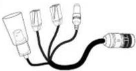 |
| RJ-45 adapter cable | 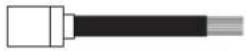 |
| Wrench |  |

Preparation
Part Names and Functions
LT913/713NI/PI series for Indoor

text_image
Diagram of a device with numbered parts, showing connections between wires and connectors1 BNC connector cover cap
2 Video output BNC connector
Supplies analog video signal (composite) to the connected device.
3 Data Port A (RJ-45)
RS-485 data communication and input data port for alarm (relay) signal.
4 Data Port B (RJ-45)
Output data port for alarm (relay) signal.
5 This port is not used.
6 This port is not used.
7 Power input jack
Connects to a AC 24 V power supply using proper cables.
8 This port is not used.
9 Locking screw
Tighten this screw to fixing the Ceiling Mount Assembly with camera body.
10 Dome Cover open button.
11 Dome Cover
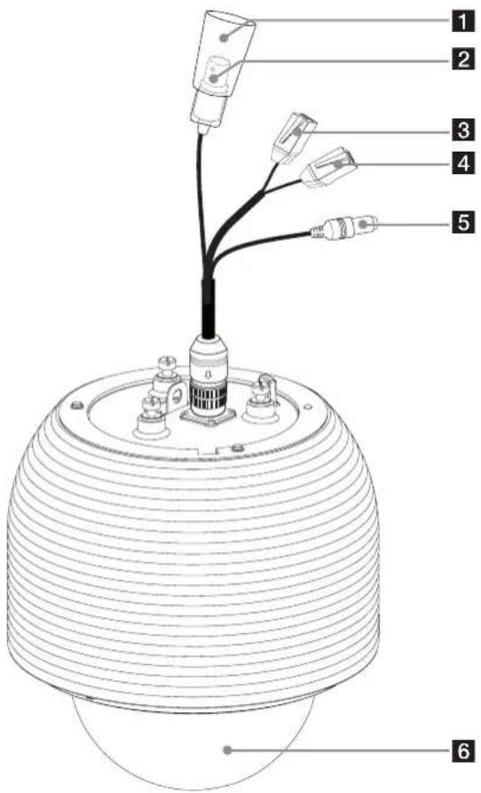
LT913/713N/P series for Outdoor
text_image
Labeled diagram of a sensor or probe device with six numbered parts, showing internal wiring and components.1 BNC connector cover cap
2 Video output BNC connector
Supplies analog video signal (composite) to the connected device.
3 Data Port A (RJ-45)
RS-485 data communication and input data port for alarm (relay) signal.
4 Data Port B (RJ-45)
Output data port for alarm (relay) signal.
5 Power input jack
Connects to a AC 24 V power supply using proper cables.
6 Dome Cover
3 Installation
Connections
Precautions
- The following steps of installation and connection work should be done by qualified service personnel or system installers and should conform to all local codes.
• Before you install and connect the camera, check and prepare the required peripheral devices and cables.
• Before you connect the camera, turn off all devices to be connected, such as this camera and DVR.
• Do not touch the dome cover's window.
Basic Connection Overview
LT913/713NI/PI series (for Indoor) LT913/713N/P series (for outdoor)

text_image
Technical diagram showing two types of security camera sensors with connected devices and cables, including a monitor and sensor components.Connecting Display device
The video signal connection between the camera and the monitor.

flowchart
graph TD
    A["Device 1"] --> B["Device 2"]
    B --> C["Device 3"]
    C --> D["Device 4"]
    D --> E["Device 5"]
    style A fill:#f9f,stroke:#333
    style B fill:#f9f,stroke:#333
    style C fill:#f9f,stroke:#333
    style D fill:#f9f,stroke:#333
    style E fill:#ccf,stroke:#333
ALARM input connection
You can connect up to 4 alarm sensors to the camera. Each alarm sensor should be connected with Alarm IN COM. You can adjust the signal state to NO (normally open) or NC (normally closed) through the setup menu.
- Connect the RJ-45 Adapter cable to the PORT A (RJ-45) cable of the camera.
- Connect the alarm device to the RJ-45 Adapter cable. When connecting lines, check and connect the color lines of the each device correctly. Refer to the below tables for color line information.

CAUTION
Do not connect one alarm sensor to the several camera's alarm input connector.
Alarm input connection

flowchart
graph TD
    A["Input"] --> B["Switch"]
    B --> C["Device 1"]
    B --> D["Device 2"]
    B --> E["Device 3"]
    B --> F["Device 4"]
    B --> G["Device 5"]
    B --> H["Device 6"]
    B --> I["Device 7"]
    B --> J["Device 8"]
    C --> K["Alarm device"]
    D --> L["Alarm device"]
    E --> M["Alarm device"]
    F --> N["Alarm device"]
    G --> O["Alarm device"]
    H --> P["Alarm device"]
    I --> Q["Alarm device"]
    J --> R["Port A"]
    K --> S["Switch"]
    L --> T["Switch"]
    M --> U["Switch"]
    N --> V["Switch"]
    O --> W["Switch"]
    P --> X["Switch"]
    Q --> Y["Switch"]
    R --> Z["Switch"]
    S --> AA["Switch"]
    T --> AB["Switch"]
    U --> AC["Switch"]
    V --> AD["Switch"]
    W --> AE["Switch"]
    X --> AF["Switch"]
    Y --> AG["Switch"]
    Z --> AH["Switch"]
| RJ-45 Adapter cable | ||
| No Description Color | ||
| 1 | RS-485 + White | |
| 2 | RS-485 - Orange | |
| 3 | NC Black | |
| 4 | ALARM IN COM Red | |
| 5 | ALARM IN 1 Green | |
| 6 | ALARM IN 2 Yellow | |
| 7 | ALARM IN 3 Blue | |
| 8 | ALARM IN 4 Brown | |
| PORT A of the LT913/713NI/PI series | |
| Description Color | |
| RS-485 + Red/White | |
| RS-485 - Black/White | |
| NC | |
| ALARM IN COM Red | |
| ALARM IN 1 White | |
| ALARM IN 2 Light Green | |
| ALARM IN 3 Yellow | |
| ALARM IN 4 | Pink |
| PORT A of the LT913/713N/P series | |
| Description Color | |
| RS-485 + Green | |
| RS-485 - Blue | |
| NC | |
| ALARM IN COM | Yellow |
| ALARM IN 1 Pink | |
| ALARM IN 2 Gray | |
| ALARM IN 3 | White |
| ALARM IN 4 Violet | |
Alarm Input function
This speed dome camera has a terminal that can sense the alarm signals.
If the alarm sensor that has installed in a door, window, safe etc. sense a touch or shock, the alarm sensor send the alarm signal to the camera and the camera will observe the sensed position.
Change the observe position to a sensor that senses a touch or shock then return to the position that previously observed. (Set the Duration Time of Alarm Input function to "3 to 255".)
| Function status | Mode |
| While observe a specific position. | Change the observe position to the alarmed position then return to the position that previously observed. |
| While operating Preset Tour function. | Stop preset touring and change the observe position to the alarmed position then restart the preset touring again. |
| While operating Auto Pan function. | Stop auto panning and change the observe position to the alarmed position then restart the auto panning again. |
| While operating Pattern function. | Stop operating pattern function and change the observe position to the alarmed position during the dwell time then restart the pattern function again. |
| in case of HOME POSITION is ON. | After Alarm has been cleared and finished the dwell time, it moves to the HOME POSITION and spend the dwell time at that position. |

NOTE
During the dwell time for alarm, you can not control the controller.
ALARM output connections
Connect the alarm device to the alarm output data port. Alarm signal output at an event occurrence. You can set the Alarm Output to the normal open or normal close mode.
- Connect the RJ-45 Adapter cable to the PORT B (RJ-45) cable of the camera.
- Connect the alarm device to the RJ-45 Adapter cable. When connecting lines, check and connect the color lines of the each device correctly. Refer to the below tables for color line information.
Alarm Out connection

flowchart
graph TD
    A["Sensor Input"] --> B["Channel 1"]
    A --> C["Channel 2"]
    A --> D["Channel 3"]
    A --> E["Channel 4"]
    A --> F["Channel 5"]
    A --> G["Channel 6"]
    A --> H["Channel 7"]
    A --> I["Channel 8"]
    B --> J["Port B"]
    C --> J
    D --> J
    E --> J
    F --> J
    G --> J
    H --> J
    I --> J
| RJ-45 Adapter cable | ||
| No Description Color | ||
| 1 | ALARM OUT [NO1] White | |
| 2 | ALARM OUT [COM1] Orange | |
| 3 | ALARM OUT [NC1] Black | |
| 4 | NC Red | |
| 5 | ALARM OUT [NO2] | Green |
| 6 | ALARM OUT [COM2] Yellow | |
| 7 | ALARM OUT [NC2] Blue |
| 8 | NC Brown |
| PORT B of the LT913/713NI/PI series | |
| Description Color | |
| ALARM OUT [NC1] Blue | |
| ALARM OUT [COM1] | Violet |
| ALARM OUT [NO1] | Brown |
| NC | |
| ALARM OUT [NC2] | Gray |
| ALARM OUT [COM2] | Orange |
| ALARM OUT [NO2] | Black |
| NC | |
| PORT B of the LT913/713/N/P series | |
| Description Color | |
| ALARM OUT [NO1] | White Blue |
| ALARM OUT [COM1] | Beige |
| ALARM OUT [NC1] | Black |
| NC | |
| ALARM OUT [NO2] | Brown |
| ALARM OUT [COM2] | Red |
| ALARM OUT [NC2] | Orange |
| NC | |
Connecting LKD1000 controller
- Connect the RJ-45 Adapter cable to the PORT A (RJ-45) cable of the camera.
- Connect the LKD1000 controller to the RJ-45 Adapter cable. (Refer to the manuals of the LKD1000 controller for more details.).
LKD1000 connection

flowchart
graph TD
    A["Router"] --> B["Switch 1"]
    B --> C["Switch 2"]
    C --> D["Switch 3"]
    D --> E["Switch 4"]
    E --> F["Switch 5"]
    F --> G["Switch 6"]
    G --> H["Switch 7"]
    H --> I["Switch 8"]
    I --> J["RJ-45 Adapter cable"]
    J --> K["Port A"]
    L["TX+"] --> M["TX-"]
    N["TX-"] --> M
    style L fill:#f9f,stroke:#333
    style M fill:#ccf,stroke:#333
| RJ-45 Adapter cable | ||
| No Description Color | ||
| 1 | RS-485 + White | |
| 2 | RS-485 - Orange | |
Connecting RS-485 device
Use the cable that is described below for RS-485 site communication.
• Shielded, twisted pair cable
- Low impedance
• Wire gauge size is thicker than AWG #22 (0.33 mm ^4 ).
RS-485 connection

flowchart
graph TD
    A["User"] --> B["RS-485 device"]
    B --> C["RJ-45 Adapter cable"]
    C --> D["Port A"]
    style A fill:#f9f,stroke:#333
    style B fill:#ccf,stroke:#333
    style C fill:#cfc,stroke:#333
    style D fill:#fcc,stroke:#333
- Connect the RJ-45 adapter cable to the PORT A (RJ-45) cable of the camera.
- Connect the RS-485 device to the RJ-45 Adapter cable. When connecting lines, connect the "Orange color line" of the RJ-45 Adapter cable to "RX -" of the RS-485 unit and "White color line" of the RJ-45 Adapter cable to "RX +" of the RS-485 unit correctly.
| RJ-45 Adapter cable | ||
| No Description Color | ||
| 1 | RS-485 + White | |
| 2 | RS-485 - | Orange |
| PORT A of the LT913/713NI/PI series | |
| Description Color | |
| RS-485 + Red/White | |
| RS-485 - Black/White | |
| PORT A of the LT913/713N/P series | |
| Description Color | |
| RS-485 + Green | |
| RS-485 - Blue | |
Connecting power source
Connect a AC 24 V power source to the power input jack.
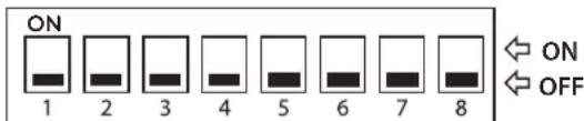
Protocol and baud rate settings
The camera has one 8-bit DIP switch blocks that determine the protocol and baud rate of the data communication. Settings are loaded when the camera boots up. Be sure to turn the camera off, change the DIP switch settings, and then power the camera back up to load the changes.
- Turn off the camera.
- Remove the dome cover.
- Remove the camera assembly cover.

- Set the DIP switches.
DIP switch locations

natural_image
Close-up of a green printed circuit board with electronic components and wires (no readable text or symbols)- Assemble the dome cover and the camera assembly cover in the reverse order.
- Power up the camera to load the changes.
Baud Rate setting
| ON | ||||||||
| 1 | 2 | 3 | 4 | 5 | 6 | 7 | 8 | OFF |
| DIP switch position | BAUD RATE(BPS) | |||
| SW1 | SW2 | SW3 | SW4 | |
| OFF | OFF | OFF | 9 600 | |
| OFF | OFF | OFF | ON 2 400 | |
| OFF | OFF | ON | OFF 4 800 | |
| OFF | ON | OFF | OFF 19 200 | |
| ON | OFF | OFF | OFF 38 400 | |
| ON | ON | ON | ON OSD Set | |
Protocol setting
| ON | |||||||||
| 1 | 2 | 3 | 4 | 5 | 6 | 7 | 8 | ON | OFF |
| DIP switch position | Protocol | |||
| SW5 SW6 SW7 SW8 | ||||
| OFF OFF | OFF OFF | LG Multix | ||
| OFF OFF | OFF | ON | Pelco D | |
| OFF OFF | ON | OFF | Pelco P | |
| ON | ON | ON | ON | OSD Set |

NOTE
If you are not using the controller with LG Multix protocol, there may be some limitation of function control.
Camera ID Setting
The camera's ID is set to "0" as factory default. If you use two or more cameras simultaneously, change the ID of the cameras.
Set the camera ID setting referring to the pictures and the table on the below.
text_image
ON 1 2 3 4 5 6 7 8 ← ON ← OFFRemoving the Protection Tape
You should remove the protection tape before installing the camera.
Remove the protection tape carefully.
For LT913/713N/P series models.
- Loosen the screws using the wrench and remove the dome cover.
- Remove the protection tape and attach the dome cover.
For LT913/713NI/PI series models.
- Press the Dome Cover open button and then disassemble the dome cover by using ALIGN mark.
- Remove the protection tape and attach the dome cover.

CAUTION
You must align the OPEN and LOCK mark correctly when you turn the dome cover to open or close. If you do not align the mark, it causes a malfunction.
Mounting the camera
You can mount the camera on the ceiling or wall.
Surface mount (optional)
Follow the instructions below to surface mount the camera.

CAUTION
The building structure must be able to support 8 kg.
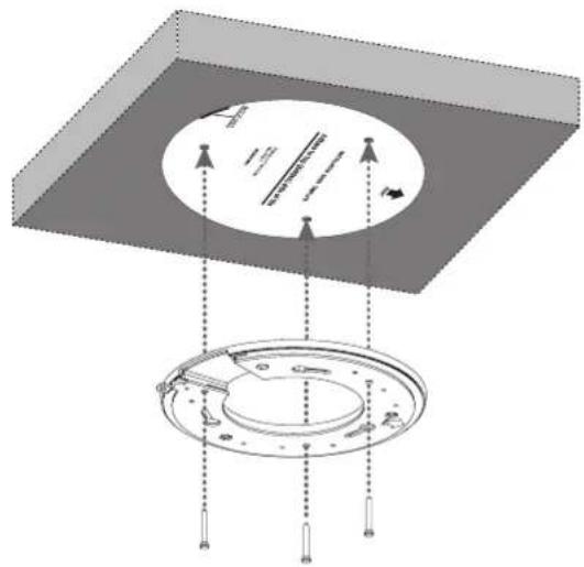
- Use the installation guide template to check the mounting location. Face the front of the label toward the area of interest.

text_image
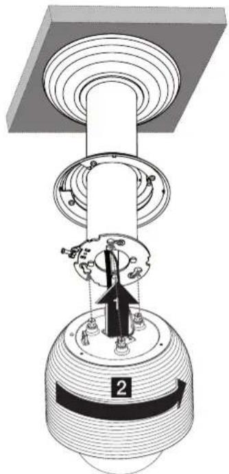
Diagram showing a 3D object with an upward arrow and a circular diagram below containing text labels and symbols.- Install the surface mounting bracket on the ceiling.
text_image
Technical diagram showing a circular component mounted on a base plate with labeled parts and directional arrows indicating assembly or alignment.- Assemble the camera and the surface mounting bracket by following step 1 and 2. Align the locking point of the surface mounting bracket and the camera.
text_image
Technical diagram showing a mechanical assembly with labeled parts and directional arrows indicating assembly steps.- Tighten the locking screw.
natural_image
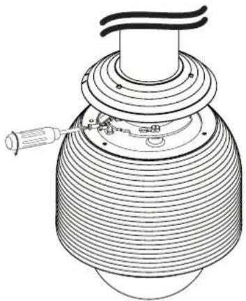
Technical line drawing of a ceiling-mounted fixture with a cylindrical component and a screwdriver (no text or symbols)- Connect the cables to the cable jacks of the camera body. After installing the camera, you should arrange the cables using the outlet box to protect the cables.

natural_image
Diagram of a rectangular device with three internal components connected by dotted lines, no text or symbols present.Ceiling mount (optional)
Follow the instructions below to mount the camera on the ceiling.

CAUTION
The building structure must be able to support 8 kg.
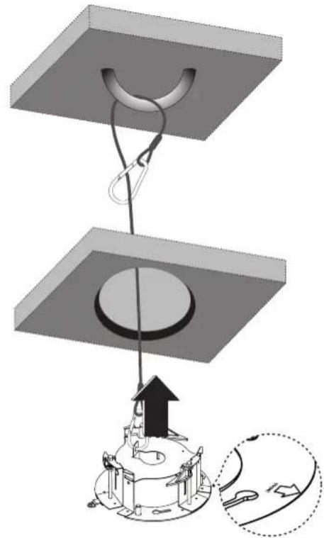
- Make a hole through the ceiling as shown below.
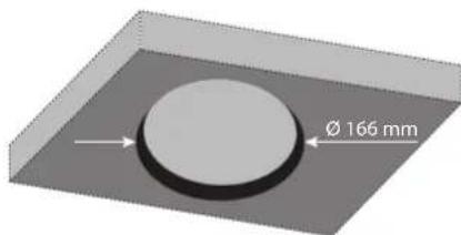
text_image
Ø 166 mm- Fasten the safety cable to the building superstructure. The building superstructure can vary depending on your installation environment.
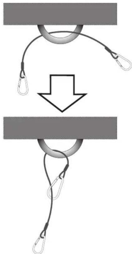
natural_image
Diagram showing rope knotting process with a downward arrow indicating motion (no text or symbols)-
Install the ceiling mounting bracket on the ceiling. Face the front of the ceiling mounting bracket toward the area of interest.
-
Pass the connection cable through the inner side of the ceiling. Connect the cables to the cable jacks of the camera body.
natural_image
Diagram of a mechanical assembly with a suspended component and an inset showing a close-up of the base (no text or symbols)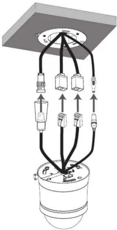
natural_image
Diagram of a mechanical or electrical component with multiple connectors and wiring, no text or symbols present.-
Tighten the screws until the ceiling mounting bracket holds the ceiling firmly.
-
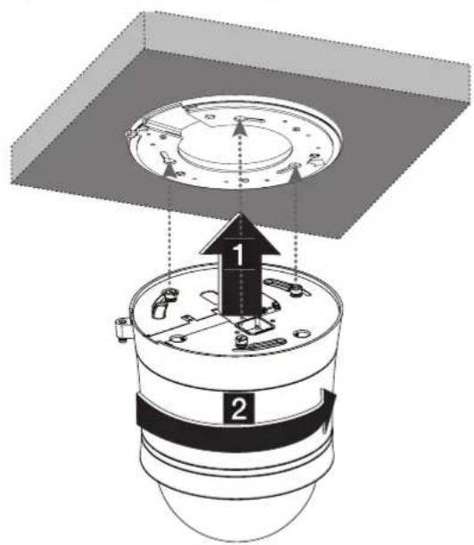
Assemble the camera and ceiling mounting bracket by following step 1 and 2. Align the locking point of the surface mounting bracket and the camera.

natural_image
3D diagram of a ceiling fixture with three hanging cylindrical components and a central circular component (no text or symbols)
text_image
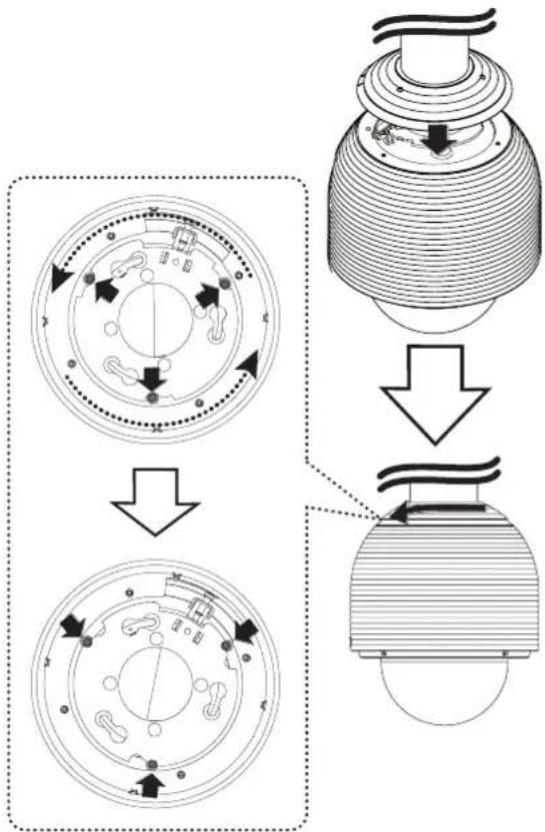
Technical diagram showing a mechanical assembly with labeled parts and directional arrows indicating motion or force.- Tighten the locking screw.
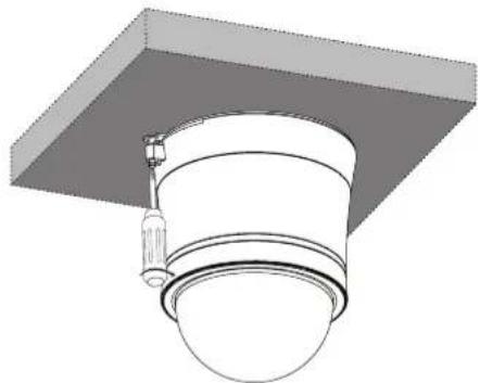
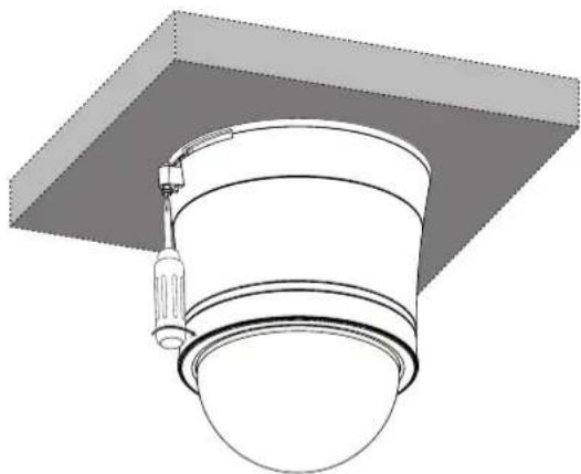
natural_image
Technical line drawing of a ceiling-mounted cylindrical component with a support bracket (no text or symbols)- Connect the cables to the cable jacks of the camera body. After installing the camera, you should arrange the cables using the outlet box to protect the cables.

natural_image
Diagram of a device with three connected ports and wires, no text or symbols presentWall mount (optional)
Install the camera by the following order.
- Connect the safety cable to the wall mount assembly.
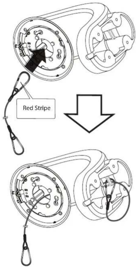
text_image
Red Stripe
CAUTION
Do not expose the connected part of the camera cable jacks in the rain or moisture.
Check the red stripe on one side of the safety cable.
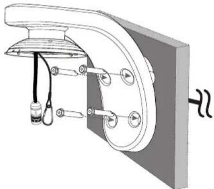
- Drill a hole on the wall where you want to install the pipe. Pass the connection cable through the wall mount assembly so that they hang down.

natural_image
Technical diagram showing a curved pipe assembly with a circular component and a separate 3D block (no text or symbols)- Install the wall mount assembly.
natural_image
Technical diagram of a mechanical assembly with labeled components (no text or symbols present)- Connect the connection cable and the safety cable to the camera body.

natural_image
Technical line drawing of a mechanical component with a curved arm and threaded base (no text or symbols)- Attach the camera to the camera assembly bracket by following step 1 and 2. Align the locking point of the wall mount assembly and the camera.
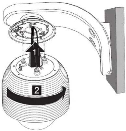
text_image
Technical diagram of a mechanical device with labeled parts and directional arrow indicating assembly or movement- Tighten the locking screw.
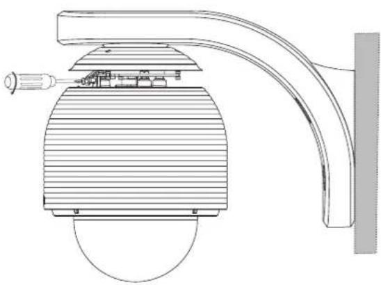
natural_image
Technical line drawing of a mechanical device with a curved bracket and circular base (no text or symbols)- Assemble the camera cover as shown below.
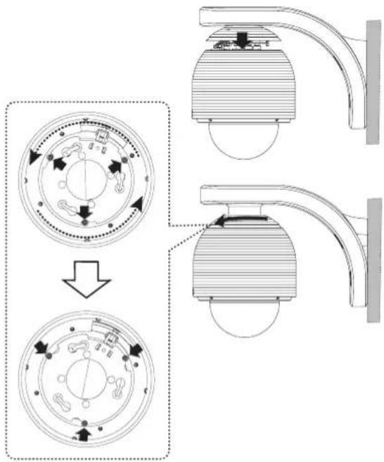
text_image
Technical diagram showing a mechanical assembly with labeled components and directional arrows indicating motion or assembly.Pendant mount (Optional)
Install the camera by the following order.
- Connect the safety cable to the pendant mount assembly.
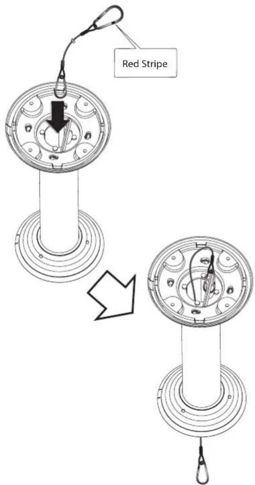
text_image
Red Stripe- Drill a hole on the wall where you want to install the pipe. Pass the connection cable through the pendant mount assembly so that they hang down.
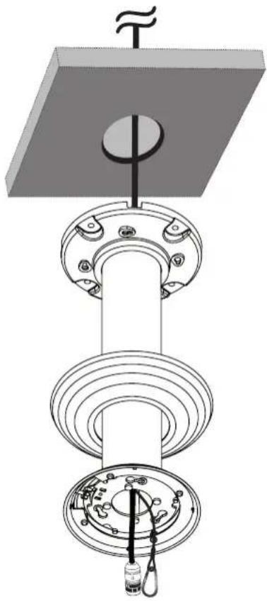
natural_image
Technical diagram of a mechanical assembly with a central shaft and flange, showing internal components and wiring (no text or labels)- Install the pendant mount assembly.
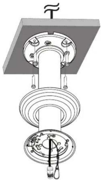
natural_image
Mechanical assembly diagram showing a rotating shaft and housing with mounting flanges (no text or symbols)- Connect the connection cable and the safety cable to the camera body.
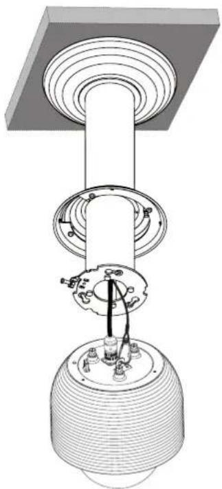
natural_image
Technical diagram of a mechanical assembly with a central column and base housing (no text or symbols)- Attach the camera to the camera assembly bracket by following step 1 and 2. Align the locking point of the wall mount assembly and the camera.
text_image
Technical diagram of a mechanical assembly with labeled components and directional arrows- Tighten the locking screw.
natural_image
Technical line drawing of a mechanical component with concentric ridges and a central shaft (no text or symbols)- Assemble the camera cover as shown below.
flowchart
graph TD
    A["Circle Component"] --> B["Sensor/Sensor Interface"]
    B --> C["Multi-layered Sensor with Radial Control"]
    C --> D["Output Sensor"]
4 Operation
Setup Menu Overview
The following table shows the list of menu items and options. You can adapt the camera to your requirements by setting up the respective items in these menus.
| 1st level 2nd level 3rd level Contents | ||||
| CAMERA SET | FOCUS | FOCUS MODE | AUTO/MANUAL/ONE PUSH/ZOOM TRIG | |
| FOCUS DIST | LT913 Series:50 CM,1.8 M,3 M,6 MLT713 Series:50 CM,1 M,3 M,5 M | |||
| RETURN | ||||
| EXPOSURE | IRIS AUTO/MANUAL | |||
| AGC OFF/LOW/MIDDLE/HIGH | ||||
| WDR/BLC OFF/WDR/BLC/HSBLC | ||||
| BRIGHTNESS 0 to 100 | ||||
| SHUTTER OFF,A.FLK,1/160,...,X2,AUTO | ||||
| SENS-UP | AUTO X2/AUTO X3/.../AUTO X128/OFF | |||
| RETURN | ||||
| WHITE BALANCE | ATW | |||
| AUTO | ||||
| MANUAL | COLOR TEMP INDOOR/OUTDOOR | |||
| RED - 100 to +100 | ||||
| BLUE - 100 to +100 | ||||
| RETURN | ||||
| ONE PUSH | ||||
| DAY/NIGHT | AUTO | D/N LEVEL LOW/MIDDLE/HIGH | ||
| DWELL TIME 5,10,15,30 | 60 SEC | |||
| RETURN | ||||
| DAY | ||||
| NIGHT | ||||
| 3D-DNR | OFF | |||
| LOW | ||||
| MIDDLE | ||||
| HIGH | ||||
| COLOR | ON COLOR -20 to 20 | |||
| OFF | ||||
| SHARPNESS 0 to 68 | ||||
| RETURN | ||||
| PAN/TILT SET | PRESET | SET PRESET | NAME OFF/ON | |
| SPEED 1 to 127 | ||||
| DWELL TIME 1 to 255 | ||||
| IRIS AUTO, 20, 40, 60, 80, 100 % | ||||
| WDR/BLC/HSBLC | OFF/ LOW WDR/ MID. WDR HIGH WDR/ LOW BLC/ MID. BLC /HIGH BLC/ LOW HSBLC/ MID. HSBLC/ HIGH HSBLC | |||
| SHUTTER | X512, ..., x2, AUTO, OFF, A.FLK, 1/160, ..., 1/90 000 | |||
| SET POSITION | ||||
| SAVE | ||||
| RETURN | ||||
| GOTO PRESET 0 to 127 | ||||
| PRESET TOUR | ||||
| CLEAR PRESET 0 to 127 | ||||
| CLEAR ALL | ||||
| FREEZE ON/OFF | ||||
| RETURN | ||||
| GROUP TOUR | SET GROUP 1 to 9 | ||
| RUN 1 to 9 | |||
| CLEAR 1 to 9 | |||
| RETURN | |||
| PATTERN | RECORD 1 to 4 | ||
| RUN 1 to 4 | |||
| RETURN | |||
| AUTO PAN | SET AUTO PAN 1 to 8 | ||
| RUN | |||
| CLEAR | |||
| RETURN | |||
| PRIVACY MASK | MASK NUMBER 1 to 8 | ||
| SET MASK | |||
| MASK STATE ON/OFF | |||
| MASK COLOR GRAY, WHITE, BLACK | |||
| WIDTH 2 to 320 | |||
| HEIGHT 3 to 240 | |||
| RETURN | |||
| SPECIAL | PROPORTIONAL PT ON/OFF | ||
| COMPASS SET/ON/OFF | |||
| HOME POSITION ON | SET | ||
| GO | |||
| DWELL TIME(0 to 100) | |||
| RETURN | |||
| AUTO RETURN OFF | |||
| TILT LIMIT ON/OFF | |||
| COMMUNICATION PROTOCOL BAUDRATE SAVE & EXIT RETURN | LG MULTIX/PELCO D/PELCO P 2 400/4 800/19 200/38 400/9 600 BPS | ||
| RETURN | ||||
| OSD SET | USER TITLE ON/OFF | |||
| ZOOM MAG ON/OFF | ||||
| FUNCTION ON/OFF | ||||
| DOME ID ON/OFF | ||||
| RETURN | ||||
| LANGUAGE | The option depends on the model. | |||
| ALARM SET | ALARM IN1 to ALARM IN4 | ON | NORMAL OPEN/CLOSE | |
| ALARM IN1 to ALARM IN4 PRESET 0 to 127 | ||||
| DWELL TIME 3 to 255 | ||||
| RETURN | ||||
| OFF | ||||
| ALARM OUT1 to ALARM OUT2 | ON | ALARM OUT1 to ALARM OUT2 ALARM IN1 to ALARM IN4 | ||
| DWELL TIME 3 to 255 | ||||
| RETURN | ||||
| OFF | ||||
| RESET | INFORMATION | |||
| INITIALIZATION | ||||
| FACTORY RESET | ||||
| RETURN | ||||
| RETURN | ||||
Menu navigation
We use the LKD1000 controller in this manual to explain the features of the LG Dome camera because of the LKD1000's ability to control all of the LG Dome camera's advanced features. (For detailed controller instructions, refer to the LKD1000 Controller Manual.)
| LKD1000 button Camera OSD operation | |
| Cam OSD button | Displays or removes the setup menu. |
| ZOOM IN button | Use to move upper direction on the menu screen. |
| ZOOM OUT button | Use to move lower direction on the menu screen. |
| FOCUS NEAR button | Use for increase the value of the option. |
| FOCUS FAR button | Use for decrease the value of the option. |
| Open/Close(Enter) buttons | Executes selections and displays a submenu for an item with the mark. |
Accessing the camera setup menu
To access the setup menus using the keys on a LKD1000 controller, do the following:
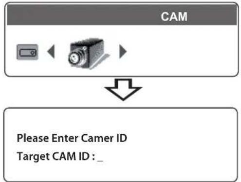
- Select CAM (Camera) icon in the main menu and then press ENTER. The camera ID input menu will be displayed.
flowchart
graph TD
    A["CAM"] --> B["Please Enter Camer ID\nTarget CAM ID : _"]
- Enter the connected camera ID to control the camera connected to the LKD1000 controller directly and then press ENTER. The camera control menu will be displayed.
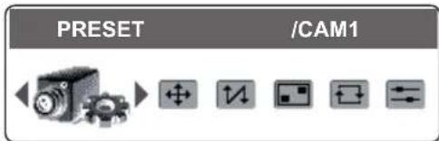
text_image
PRESET /CAM1- Press [Cam OSD] button to display the camera setup menu.
At this point, you have access to the camera setup menu.
General operation
- Use [In] or [Out] button to select an option then press [Open] or [Close] button. Submenu appears on the monitor.
- Use [In] or [Out] button to select a submenu option.
- Use [Near] or [Far] button to select a value.
- Select [RETURN] option then press [Open] or [Close] to return to the previous menu.
- Press [Cam OSD] button to exit the setup menu.
Camera menu settings
Focus setting
The camera adjusts the focus automatically by sensing the center of the picture.

text_image
[CAMERA SET MENU] ►FOCUS ↓ EXPOSURE ↓ WHITE BALANCE AUTO DAY/NIGHT AUTO↓ 3D-DNR MIDDLE COLOR ON↓ SHARPNESS 34 ...... RETURN ↓ [FOCUS MENU] ►FOCUS MODE AUTO FOCUS DIST 50CM RETURN ↓Focus mode
Select [FOCUS MODE] option on the [FOCUS] menu, then select the following mode.
• AUTO: Auto-focus is activated automatically.
- MANUAL: Focus is activated automatically after the zoom movement is finished. If you want to control the focus manually, press the FOCUS (NEAR or FAR) buttons on the controller.
- ONE PUSH: The focus is activated manually. If the camera is received auto-focus command, the camera is activated auto-focus mode and the focus is set automatically and then the focus mode is automatically changed to manual mode.
• ZOOM TRIG: The focus is activated manually. If you change the zoom, the focus is activated automatically and then the focus mode is automatically changed to manual mode.
Focus Distance setting
Selects the minimum shooting distance for the focus. Select [FOCUS DIST] option on the [FOCUS] menu, then select a focus distance value.
Exposure settings
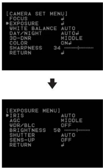
text_image
[CAMERA SET MENU] FOCUS ►EXPOSURE WHITE BALANCE AUTO DAY/NIGHT AUTO 3D-DNR MIDDLE COLOR ON SHARPNESS 34 ............. RETURN ↓ [EXPOSURE MENU] ►IRIS AUTO AGC MIDDLE WDR/BLC OFF BRIGHTNESS 50 ............. SHUTTER AUTO SENS-UP OFF RETURN ↓Iris setting
Select the desired lens iris value for camera exposure. Select [IRIS] option on the [EXPOSURE] menu, then select a value.
• AUTO: The lens iris is set automatically.
• MANUAL: Use [Near] or [Far] button to select the DC Iris level. DC Iris level are set by one parameter unit.
AGC (Automatic Gain Control) setting
If the images are too dark, change the maximum [AGC] value to make the images bright.
- Select [AGC] option on the [EXPOSURE] menu.
- Use [Near] or [Far] button to select a mode.
WDR/BLC setting
Use WDR/BLC option to set the options for BLC or WDR camera.
- Select [WDR/BLC] option on the [EXPOSURE] menu.
-
Use [Near] or [Far] button to select a mode then press [Open] or [Close].
-
WDR LEVEL: WDR (Wide dynamic range) feature can be very helpful to cope with very challenging lighting conditions. It is capable of capturing both of the dark part and bright part and combining the differences into a scene to generate a highly realistic image as original scene. Set the WDR level (LOW, MIDDLE, HIGH).
- BLC LEVEL: Camera's backlight compensation feature helps alleviate issues of visibility in high contrast areas. Set the BLC level (LOW, MIDDLE, HIGH).
- HSBLC: Use for masking brightness of the specific area to view the subject more clearly.
- HSBLC LEVEL: Select the HSBLC level. (LOW, MIDDLE, HIGH).
- COLOR: Use [Near] or [Far] button to select a color.
- OFF: Not used.
BRIGHTNESS setting
You can increase the brightness of the darkened video. If you set the brightness to lower value, the image is darkened. If you set the brightness to higher value, the image gets bright.
- Select [BRIGHTNESS] option on the [EXPOSURE] menu.
- Use [Near] or [Far] button to set the bright level.
SHUTTER (Shutter Speed) setting
Select the desired shutter speed for camera exposure. You can change the shutter speed to higher speed to capture fast-moving subjects, though the image becomes darker.
- Select [SHUTTER] option on the [EXPOSURE] menu.
- Use [Near] or [Far] button to set shutter speed.
SENS-UP setting
If pictures are not clear due to darkness, use this function to increase the sensitivity of picture.
- Select [SENS-UP] option on the [EXPOSURE] menu.
- Use [Near] or [Far] button to set the SENS-UP limit. To set the SENS-UP function, select the [AUTO] on the [SHUTTER].

NOTE
If you set to one of the SHUTTER options except AUTO on the [SHUTTER] menu, the [SENS-UP] setting is not available and [---] mark is displayed.
White Balance setting
Select the method by which the camera shifts its output colors to compensate for the color of a light source.

text_image
[CAMERA SET MENU] FOCUS EXPOSURE WHITE BALANCE AUTO DAY/NIGHT AUTO 3D-DNR MIDDLE COLOR ON SHARPNESS 34 RETURN- Select [WHITE BALANCE] option on the [CAMERA SET] menu.
- Use [Near] or [Far] button to select a mode then press [Open] or [Close].
- ATW (Auto-Tracing White Balance): In this mode, the color temperature range for the proper white balance is approximately from 1 800 K to 10 500 K. Proper white balance may not be obtained under the following conditions:
- When the color temperature is out of the 1 800 K to 10 500 K range.
- When the scene mostly contains high color
temperature objects, such as a blue sky or sunset.
- When the scene is dim.
- AUTO: In this mode, the color temperature range for the proper white balance is approximately 2 700 K to 5 400 K. Proper white balance may not be obtained under the following conditions:
- When the color temperature is out of the 2 700 K to 5 400 K range.
- When the scene mostly contains high color temperature objects, such as a blue sky or sunset.
- When the scene is dim.
- ONE PUSH: If you select the ONE PUSH mode, you will be able to set up the White Balance automatically using [Open] or [Close] button.
- MANUAL: You can set the white balance options manually.
- COLOR TEMP: Use [Near] or [Far] button to select a function.
INDOOR: The color temperature range for the proper white balance is approximately 3200 K.
OUTDOOR: The color temperature range for the proper white balance is approximately 5 100 K.
- RED: Set the desired red value. (-100 to 100)
- BLUE: Set the desired blue value. (-100 to 100)
Day/Night setting
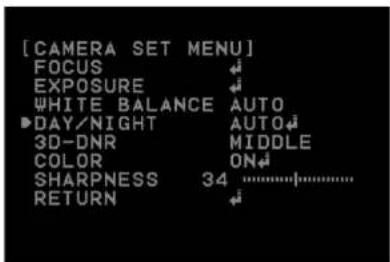
text_image
[CAMERA SET MENU] FOCUS EXPOSURE WHITE BALANCE AUTO DAY/NIGHT AUTO 3D-DNR MIDDLE COLOR ON SHARPNESS 34 ...... RETURN-
Select [DAY/NIGHT] option on the [CAMERA SET] menu.
-
Use [Near] or [Far] button to select the mode.
- AUTO: You will be able to change the Day/Night mode automatically.
- D/N LEVEL: Use [Near] or [Far] button to select a level.
- DWELL TIME: Use [Near] or [Far] button to select a dwell time.

NOTE
If you set the AGC to [OFF] or the SHUTTER is set to one of the SHUTTER options except AUTO on the [EXPOSURE] menu, the AUTO mode of the DAY/NIGHT function is not available and [---] mark is displayed.
• DAY: Color mode enabled.
• NIGHT: Black-and-white mode enabled.
3D-DNR setting

text_image
[CAMERA SET MENU] FOCUS EXPOSURE WHITE BALANCE AUTO DAY/NIGHT AUTO ►3D-DNR MIDDLE COLOR ON SHARPNESS 34 ............. RETURN- Select [3D-DNR] option. If pictures are not clear due to brightness, use this function to reduce the noise of picture.
- Use [Near] or [Far] button to select a option.

NOTE
• If you set the AGC to [OFF] on the [EXPOSURE] menu, the [3D-DNR] function is not available.
- When you use this function, the afterimage may occur.
Color setting
You can switch the displayed picture to grayscale or color.

text_image
[CAMERA SET MENU] FOCUS ↔ EXPOSURE ↔ WHITE BALANCE AUTO DAY/NIGHT AUTO↔ 3D-DNR MIDDLE ▶COLOR ON↔ SHARPNESS 34 ······················· RETURN ←- Select [COLOR] option on the [CAMERA SET] menu.
-
Use [Near] or [Far] button to change a color effect.
-
ON: To display the picture with color. Select ON and press [Open] or [Close] to display the submenu. You can adjust the color level using the [Near] or [Far] button.
• OFF: To display the picture with grayscale.
Sharpness setting
Sharpens the image outline.

text_image
[CAMERA SET MENU] FOCUS ↔ EXPOSURE ↔ WHITE BALANCE AUTO DAY/NIGHT AUTO↔ 3D-DNR MIDDLE COLOR ON↔ ▶SHARPNESS 34 ............. RETURN- Select [SHARPNESS] option on the [CAMERA SET] menu.
- Use [Near] or [Far] button to adjust the option. If you set the sharpness value to higher, the image outline becomes sharp. If you set to lower value, the image outline becomes dim.
PAN/TILT Settings
Preset setting
Preset position is the function to register camera monitoring positions (preset positions) associated with position numbers. By entering the position numbers, you can move cameras to the preset positions.

text_image
[MENU] CAMERA SET ▶PAN/TILT SET OSD SET LANGUAGE ENG ALARM SET RESET RETURN [PAN/TILT MENU] ▶PRESET GROUP TOUR PATTERN AUTO PAN PRIVACY MASK SPECIAL RETURNTo register preset positions
- Select the [SET PRESET] option on the [PRESET] menu.
- Use the [Near] or [Far] button to select the preset number you wish to register and press the [Open] or [Close] button.
- Set the preset name.
How to set the preset name.
- Set the NAME option to [ON] and press [Open] or [Close] button.
-
Use [In], [Out], [Near] or [Far] button to select a character, number, symbol mark or option item.
-
</> : Moves cursor to left or right.
• (Blank): Insert a space at the cursor position. -
CLR: If you enter the wrong code, select [CLR] then press [Open] or [Close] to delete. All letters will be erased at once.
• SAVE: Select this option to confirm the settings.
• EXIT: Select this option to exit the settings. -
Press [Open] or [Close] button to confirm your selection.
-
Select the speed to move to the preset position.
-
Select the preset tour dwell time.
-
Set the IRIS option. IRIS LEVEL are set by 20 % unit (20%, 40%, 60%, 80%, 100%)
-
Set the WDR/BLC/HSBLC option.
-
Set the SHUTTER option.
-
Select the [SET POSITION] option and press [Open] or [Close] button.
-
Move the camera to a point you wish by using the joystick and then press [Open] or [Close] button to save it.
-
Select [SAVE] option and press [Open] or [Close] button to confirm the settings. The position and its number are memorized.
-
Repeat steps 1 to 11 to add additional positions.
-
Select [RETURN] option and press [Open] or [Close] button to exit the setting menu.
Changing a picture in a preset position
The preset function makes the combination camera move to the programmed preset position. It is necessary to program preset positions for the combination camera beforehand.
- Select [GOTO PRESET] option on the [PRESET] menu.
- Select the memorized preset position's index number then press [Open] or [Close] button. The camera moves to the preset position and the picture of the camera in that position appears on the monitor.
To tour the preset positions
You can tour all preset positions.
-
Select [PRESET TOUR] option on the [PRESET] menu. All registered preset positions in the camera will be selected and the camera position image will be switched on the active monitor.
-
You can stop the tour by moving the joystick or pressing any button.
To clear the preset position
You can clear a memorized preset position.
- Select [CLEAR PRESET] option on the [PRESET] menu.
- Selects the memorized preset index number then press [Open] or [Close] button to clear the preset positions.
To clear all the preset positions
You can clear all of the memorized preset positions at once.
- Select [CLEAR ALL] option on the [PRESET] menu.
- Press [Open] or [Close] button to clear the all preset positions.
Freeze function
- Select [FREEZE] option on the [PRESET] menu.
- Use [Near] or [Far] button to set up the [ON] or [OFF].
Group tour setting
You can create a group using preset positions that are registered already. A maximum of 9 groups is available.
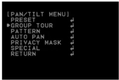
text_image
[PAN/TILT MENU] PRESET GROUP TOUR PATTERN AUTO PAN PRIVACY MASK SPECIAL RETURN

text_image
[GROUP TOUR MENU] ▶SET GROUP 1 RUN 1 CLEAR 1 RETURNTo set the group
- Select [SET GROUP] option on the [GROUP TOUR] menu.
- Select the group number and press [Open] or [Close] button.
- Set the group item. You can set the group item up to 8.
- Select [SAVE] option and press [Open] or [Close] button to confirm the settings.
- Select [RETURN] option and press [Open] or [Close] button to exit the setting menu.
To tour the group
You can tour the group that is registered already.
- Select [RUN] option on the [GROUP TOUR] menu.
- Select the group number and press [Open] or [Close] button. The camera moves to the preset position in the group and the picture of the camera in that position appears on the monitor.
To delete a group
You can delete a memorized group.
- Select [CLEAR] option on the [GROUP TOUR] menu.
- Select the group number and press [Open] or [Close] button. The group will be deleted.
Pattern setting
You can activate the camera in a repeating pattern. The pattern is programmed by recording your manual pan, tilt, and zoom operations. The camera stores the movements you performed in memory.

text_image
[PAN/TILT MENU] PRESET GROUP TOUR ▶PATTERN AUTO PAN PRIVACY MASK SPECIAL RETURN [PATTERN MENU] ▶RECORD 1 RUN 1 RETURNTo record the pattern
- Select [RECORD] option on the [PATTERN] menu.
- Select the recording number and press [Open] or [Close] button. The pattern recording is started
- Move the camera through the desired movement.
- Press [Open] or [Close] button to stop the pattern recording.

NOTE
The available total time of pattern differs depending on operation.
To play the pattern
- Select [RUN] option on the [PATTERN] menu.
- Select the recording number and then press [Open] or [Close] button to play the programmed pattern. The tour will play indefinitely until you stop it by moving the joystick or pressing any button.
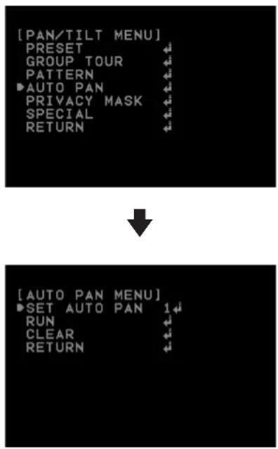
Auto Pan setting
By selecting the Auto Pan number, the camera pans automatically.
text_image
[PAN/TILT MENU] PRESET GROUP TOUR PATTERN AUTO PAN PRIVACY MASK SPECIAL RETURNTo set the Auto Pan position
- Select [SET AUTO PAN] option on the [AUTO PAN] menu.
- Select the number you wish to register and press [Open] or [Close] button.
- Select the moving speed.
- Select the Auto pan dwell time.
- Move the camera to the desired start point by using the joystick.
- Select the [SET POSITION] option and press [Open] or [Close] button.
- Move the camera to the desired end point by using the joystick and then press [Open] or [Close] button.
- Repeat steps 1 to 7 to add additional positions.
- Select [RETURN] option and press [Open] or [Close] button to exit the setting menu.

NOTE
If you press the [CLEAR] Option during the Auto paning, All of AUTO PAN position will be deleted.
To play the auto pan
You can play the camera with auto pan function.
- Select [RUN] option on the [AUTO PAN] menu.
- You can stop the Auto pan function by moving the joystick or pressing any button.
To delete the auto pan position
You can delete the memorized auto pan position.
- Select [AUTO PAN] option on the [PAN/TILT] menu.
- Select [CLEAR] option then press [Open] or [Close] button to delete the Auto pan position.
Privacy Mask setting
This function is aiming at the protection of personal privacy, the mask zone is not displayed on the screen. Up to 8 zones can be registered.

text_image
[PAN/TILT MENU] PRESET GROUP TOUR PATTERN AUTO PAN ▶PRIVACY MASK SPECIAL RETURN [PRIVACY MASK MENU] ▶MASK NUMBER 1 SET MASK MASK STATE ON MASK COLOR BLACK WIDTH 320 ...... HEIGHT 240 ...... RETURN- Select [PRIVACY MASK] option on the [PAN/TILT MENU].
- Press [Open] or [Close] button to display the PRIVACY MASK MENU.
- Use [Near] or [Far] button to select a zone number on the [MASK NUMBER] option.
-
Select the [SET MASK] option and press [Open] or [Close] button.
-
Select the mask zone using the joystick and then press [Open] or [Close] button to save it.
- Use [Near] or [Far] button to set up the [ON] or [OFF] on the [MASK STATE] option. If you already registered the mask zone and set to ON, the mask zone box appears on the monitor.
- Use [Near] or [Far] button to select the color of the mask zone box on the [MASK COLOR] option.
- Select the [WIDTH] option and use [Near] or [Far] button to adjust the horizontal size of the mask zone box.
- Select the [HEIGHT] option and use [Near] or [Far] button to adjust the vertical size of the mask zone box.
- Repeat steps 3 to 9 to add additional positions.

NOTE
- The parts with the registered mask numbers from 1 to 4 have the same color. (So do the parts with the numbers from 5 to 8). If you change the mask color, the registered mask color will be changed automatically with the same color for each of group (1 to 4, 5 to 8).
- The initial PRIVACY MASK color is set to black. After setting, the PRIVACY MASK position on [SET MASK] option, it'll be changed to gray color. Be sure, you have to press [Open] or [Close] button on the [SET MASK] option to confirm the privacy mask color.
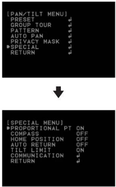
Special setting
text_image
[PAN/TILT MENU] PRESET GROUP TOUR PATTERN AUTO PAN PRIVACY MASK ▶SPECIAL RETURNProportional PT
This function optimizes the image by automatically adjusting the PAN/TILT (horizontal/vertical rotation) speed according to the zoom ratio.
- Select [PROPORTIONAL PT] option on the [SPECIAL] menu.
- Use [Near] or [Far] button to toggle it on and off.
• ON : Pan/tilt speed is in inverse proportion to the zoom ratio.
• OFF: The speed is constant at the fastest level regardless of the zoom ratio.
Compass
You can display the north, south, east and west information on the screen.
- Select [COMPASS] option on the [SPECIAL] menu.
- Set the [COMPASS] option to [SET] and then press [Open] or [Close] button.
- Select north point using the joystick and then press [Open] or [Close] button.
- Set the [COMPASS] option to [ON].
Home position
The home position is the camera's basic position.
The camera returns to this position whenever you want.
Use the following procedure to make the home position.
- Select [HOME POSITION] option on the [SPECIAL] menu.
- Use [Near] or [Far] button to set it ON.
- Press [Open] or [Close] button.
- Select [SET] option and then press [Open] or [Close] button.
- Select the home position where you want and then press [Open] or [Close] button.
- Select [DWELL TIME] option and then select the dwell time.
- Select [RETURN] option and press [Open] or [Close] button to exit the setting menu.
Go to Home position
- Select [HOME POSITION] option on the [SPECIAL] menu.
- Use [Near] or [Far] button to set it ON.
- Press [Open] or [Close] button.
- Select [GO] option and then press [Open] or [Close] button. The camera will move to the home position.

NOTE
- If you do not want to use the home position function, set the [HOME POSITION] option to [OFF].
- If you set the [HOME POSITION] to [ON], the [AUTO RETURN] option is set to [OFF] automatically and you can not use it.
Auto return
This function can be used to specify automatic return to a particular mode if a certain amount of time elapses without any operation being performed.
- Select [AUTO RETURN] option on the [SPECIAL] menu.
- Use [Near] or [Far] button to set it [ON] and then press [Open] or [Close] button.
- Select [RETURN TIME] option and then select the auto return time.
- Select [RETURN] option and press [Open] or [Close] button to exit the setting menu.

NOTE
If you set [AUTO RETURN] to [ON], the [HOME POSITION] option is set to [OFF] automatically and you can not use it.
Tilt limit
You can specify the tilt range. If you set this function, the camera is able to tilt from 15^ to 165^ .
- Select [TILT LIMIT] option on the [SPECIAL] menu.
- Use [Near] or [Far] button to set it [ON]. If you do not want to use this function, set it to [OFF].
Communication
This setting is required to establish a connection between the system controller and the camera.
- Select [COMMUNICATION] option on the [SPECIAL] menu.
- Press [Open] or [Close] button.
-
Set the below options.
-
Protocol: This item lets you set a protocol for RS-485 communication. Select the desired protocol.
- Baud Rate: Select the desired speed of communication between the system controller and the camera. Confirm selected parameter to the baud rate of the system controller.
- SAVE & EXIT: Select this option and then press [Open] or [Close] button to save the communication settings and exit the setting menu.
OSD Settings

text_image
[MENU] CAMERA SET PAN/TILT SET ■OSD SET LANGUAGE ENG ALARM SET RESET RETURN ↓ [OSD MENU] ■USER TITLE OFF ZOOM MAG OFF FUNCTION OFF DOME ID OFF RETURNUser title setting
You can use the camera identification to assign a number and character to the camera.
- Select [USER TITLE] option on the [OSD] menu.
- Use [Near] or [Far] button to set it [ON].
- Press [Open] or [Close] button. The USER TITLE menu appears.
- Use [In], [Out], [Near] or [Far] button to select a character, number, symbol mark or option item.

text_image
[USER TITLE] ABCDEFGHIJKLMNOPQRSTUVWXYZ abcdefghijklmnopqrstuvwxyz - :0123456789 [ ]< > CLR POS END [ ]• </> : Moves cursor to left or right.
• 1 (Blank): Insert a space at the cursor position.
- CLR: If you enter the wrong code, select [CLR] then press [Open] or [Close]. All letters will be erased at once.
• POS: Move the USER TITLE position on the screen using the [Near] or [Far] buttons.
• END: Select this option to exit the settings.
ZOOM MAG setting
Displays or removes the zoom OSD on the screen.
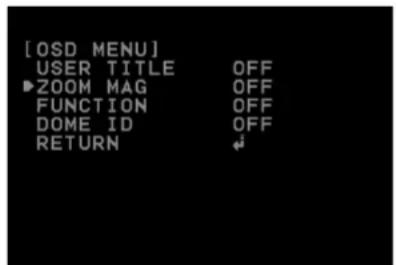
text_image
[OSD MENU] USER TITLE OFF ►ZOOM MAG OFF FUNCTION OFF DOME ID OFF RETURN ↕- Select [ZOOM MAG] option on the [OSD] menu.
- Use [Near] or [Far] button to set it [ON] or [OFF].
- Select [RETURN] option and press [Open] or [Close] button to exit the setting menu.
FUNCTION setting
Displays or removes the Function OSD on the screen.
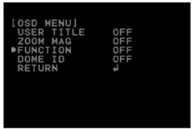
text_image
[OSD MENU] USER TITLE OFF ZOOM MAG OFF ▶FUNCTION OFF DOME ID OFF RETURN ↓- Select [FUNCTION] option on the [OSD] menu.
- Use [Near] or [Far] button to set it [ON] or [OFF].
- Select [RETURN] option and press [Open] or [Close] button to exit the setting menu.
DOME ID setting
Displays or removes the Camera ID OSD on the screen.
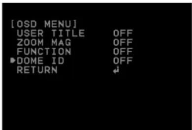
text_image
[OSD MENU] USER TITLE OFF ZOOM MAG OFF FUNCTION OFF ►DOME ID OFF RETURN ↕- Select [DOME ID] option on the [OSD] menu.
- Use [Near] or [Far] button to set it [ON] or [OFF]
- Select [RETURN] option and press [Open] or [Close] button to exit the setting menu.
LANGUAGE Setting
Select a language for the setup menu and OSD display.

text_image
[MENU] CAMERA SET ← PAN/TILT SET ← OSD SET ← ▶LANGUAGE ENG ALARM SET ← RESET ← RETURN ←ALARM Setting
This camera has a terminal that can sense the alarm signals. The camera can be programmed to go to a preset with a signal from any connected alarm device.

text_image
[MENU] CAMERA SET PAN/TILT SET OSD SET LANGUAGE ENG ▶ALARM SET RESET RETURN
text_image
[ ALARM MENU ] ►ALARM IN1 OFF ALARM IN2 OFF ALARM IN3 OFF ALARM IN4 OFF ALARM OUT1 OFF ALARM OUT2 OFF RETURNAlarm In setting
- Select one of the alarms in option on the [ALARM SET] menu.
- Use [Near] or [Far] button to set it [ON].
- Press [Open] or [Close] button.
- Select [NORMAL] option and select [Open] or [Close] option.
• OPEN: Activate the alarm in the close position.
• CLOSE: Activate the alarm in the open position.
- Select [ALARM IN(1 to 4)] option and select preset number. When the alarm is triggered, the camera moves to the selected preset position. The presets run continuously until alarm source is off.
- Select [DWELL TIME] option and then set the alarm dwell time. The alarm is stopped after selected dwell time.
Alarm Out setting
- Select one of the alarm out options on the [ALARM SET] menu.
- Use [Near] or [Far] button to set it [ON].
- Press [Open] or [Close] button.
- Select alarm input number. When the selected alarm input is triggered, the alarm signal is outputted.
- Select [DWELL TIME] option and then set the alarm dwell time. The alarm output is stopped after selected dwell time.
RESET Setting
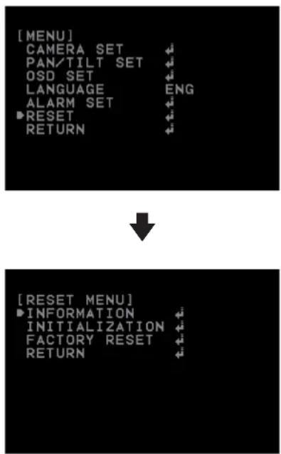
text_image
[MENU] CAMERA SET PAN/TILT SET OSD SET LANGUAGE ENG ALARM SET ■RESET RETURN ↓ [RESET MENU] ■INFORMATION INITIALIZATION FACTORY RESET RETURNInformation
You can view the current camera information such as PTZ software version, camera software version, camera ID, Protocol and Baud Rate.
- Select [INFORMATION] option on the [RESET] menu.
- Press [Open] or [Close] button to display the current camera information.
Initialization
You can initialize the camera settings.
- Select [INITIALIZATION] option on the [RESET] menu.
- Press [Open] or [Close] button then confirmation window is displayed.
- Select [YES] and press [Open] or [Close] button.
Factory reset
Clear certain settings and information and return to factory default settings.
- Select [FACTORY RESET] option on the [RESET] menu.
- Press [Open] or [Close] button then confirmation window is displayed.
- Select [YES] and press [Open] or [Close] button. The camera will return to the factory default settings.
5
Appendix
Specifications
LT913N/P series
| Model LT913N LT913P | ||
| Signal System NTSC (High Resolution) PAL (High Resolution) | ||
| Pick-Up Device 4.5 mm EX-view HAD CCD | ||
| Total Pixels No 410 000 Pixels 470 000 Pixels | ||
| Horizontal Resolution More Than 540 TV Lines | ||
| Lens x37 Zoom ( F1.5 (Wide Angle), F4.1 (Tele)), f = 3.5 mm to 129 mm | ||
| S/N Ratio More Than 50 dB (AGC Off ) | ||
| Day & Night | Day / Night / Auto | |
| Minimum Illumination(lx) | Color: 0.003 lx (0.6, Sens-up Off), B/W: 0.000 1 lx (0.1, Sens-up Off) | |
| Digital Zoom | X 12 | |
| Sync System | Internal | |
| White Balance | AUTO / ONE PUSH / MANUAL / ATW | |
| Control method | RS-485 Control | |
| Alarm Input | 4 Channel | |
| Alarm Output | 2 Channel | |
| Video Output | Composite Output 1 Vp-p ( 75 Ω Terminated) | |
| Electronic Shutter | 1/60 to 1/90 000 second | 1/50 to 1/90 000 second |
| Iris Control | Auto / Manual | |
| Wide Dynamic Range | Dual Shutter Control (62 dB) | |
| Panning Range (Speed) 0 | ° to 360° (Endless), Maximum 400°/second | |
| Tilting Range (Speed) 0 | ° to 180°, Maximum 400°/second | |
| Privacy Zone 8 area active programmable zone | ||
| Preset/ID 128 position / 256 | ||
| Auto Panning 2 to 8 points | ||
| Pattern 4 | ||
| Group Tour Maximum 9 groups | ||
| Operating Temperature -20 °C to 50 °C (Humidity: 0 % RH to 80 % RH) | ||
| Safekeeping Temperature -30 °C to 60 °C (Humidity: 0 % RH to 90 % RH) | ||
| Power Supply AC 24 V | ||
| Power Consumption 18 W | ||
| Dimension(∅ x H ) 234.6 mm X 269.9 mm | ||
| Weight 3.7 kg | ||
LT913NI/PI series
| Model | LT913NI | LT913PI |
| Signal System | NTSC (High Resolution) | PAL (High Resolution) |
| Pick-Up Device | 4.5 mm EX-view HAD CCD | |
| Total Pixels No | 410 000 Pixels | 470 000 Pixels |
| Horizontal Resolution | More Than 540 TV Lines | |
| Lens | x37 Zoom ( F1.5(Wide Angle), F4.1(Tele)), f = 3.5 mm to 129 mm | |
| S/N Ratio | More Than 50 dB (AGC Off) | |
| Day & Night | Day / Night / Auto | |
| Minimum Illumination(lx) | Color: 0.003 lx (0.6, Sens-up Off), B/W: 0.000 1 lx (0.1, Sens-up Off) | |
| Digital Zoom | X 12 | |
| Sync System | Internal | |
| White Balance | AUTO / ONE PUSH / MANUAL / ATW | |
| Control method | RS-485 Control | |
| Alarm Input 4 Channel | ||
| Alarm Output 2 Channel | ||
| Video Output Composite Output 1 Vp-p (75 Ω Terminated) | ||
| Electronic Shutter 1/60 to 1/90 000 second 1/50 to 1/90 000 second | ||
| Iris Control Auto / Manual | ||
| Wide Dynamic Range Dual Shutter Control (62 dB) | ||
| Panning Range (Speed) 0 | ° to 360° (Endless), Maximum 400°/second | |
| Tilting Range (Speed) 0 | ° to 180°, Maximum 400°/second | |
| Privacy Zone 8 area active programmable zone | ||
| Preset/ID 128 position / 256 | ||
| Auto Panning 2 to 8 points | ||
| Pattern 4 | ||
| Group Tour Maximum 9 groups | ||
| Operating Temperature | -10 °C to 50 °C (Humidity: 0 % RH to 80 % RH) | |
| Safekeeping Temperature | -30 °C to 60 °C (Humidity: 0 % RH to 90 % RH) | |
| Power Supply | AC 24 V | |
| Power Consumption | 14 W | |
| Dimension(∅ x H) | 205.8 mm X 247.4 mm | |
| Weight | 2.4 kg | |
LT713N/P series
| Model LT713N LT713P | ||
| Signal System NTSC (High Resolution) PAL (High Resolution) | ||
| Pick-Up Device 4.5 mm EX-view HAD CCD | ||
| Total Pixels No 410 000 Pixels 470 000 Pixels | ||
| Horizontal Resolution More than 540 TV Lines | ||
| Lens x27 Zoom ( F1.5 (Wide Angle), F3.8 (Tele Photo)), f = 3.25 mm to 88 mm | ||
| S/N Ratio More Than 50 dB (AGC Off) | ||
| Day & Night | Day / Night / Auto | |
| Minimum Illumination(lx) | Color: 0.003 lx (0.6, Sens-up Off), B/W: 0.000 1 lx (0.1, Sens-up Off) | |
| Digital Zoom | X 12 | |
| Sync System | Internal | |
| White Balance | AUTO / ONE PUSH / MANUAL / ATW | |
| Control method | RS-485 Control | |
| Alarm Input | 4 Channel | |
| Alarm Output | 2 Channel | |
| Video Output | Composite Output 1 Vp-p (75 Ω Terminated) | |
| Electronic Shutter | 1/60 to 1/90 000 second | 1/50 to 1/90 000 second |
| Iris Control | Auto / Manual | |
| Wide Dynamic Range | Dual Shutter Control (62 dB) | |
| Panning Range (Speed) | 0° to 360° (Endless), Maximum 400°/second | |
| Tilting Range (Speed) | 0° to 180°, Maximum 400°/second | |
| Privacy Zone | 8 area active programmable zone | |
| Preset/ID | 128 position / 256 | |
| Auto Panning | 2 to 8 points | |
| Pattern | 4 | |
| Group Tour | Maximum 9 groups | |
| Operating Temperature | -20 °C to 50 °C (Humidity: 0 % RH to 80 % RH) | |
| Safekeeping Temperature | -30 °C to 60 °C (Humidity: 0 % RH to 90 % RH) | |
| Power Supply | AC 24 V | |
| Power Consumption | 18 W | |
| Dimension(∅x H ) | 234.6 mm X 269.9 mm | |
| Weight | 3.7 kg | |
LT713NI/PI series
| Model LT713NI LT713PI | ||
| Signal System NTSC (High Resolution) PAL (High Resolution) | ||
| Pick-Up Device 4.5 mm EX-view HAD CCD | ||
| Total Pixels No 410 000 Pixels 470 000 Pixels | ||
| Horizontal Resolution More than 540 TV Lines | ||
| Lens x27 Zoom ( F1.5 (Wide Angle), F3.8 (Tele Photo)), f = 3.25 mm to 88 mm | ||
| S/N Ratio More Than 50 dB (AGC Off) | ||
| Day & Night | Day / Night / Auto | |
| Minimum Illumination(lx) | Color: 0.003 lx (0.6, Sens-up Off), B/W: 0.000 1 lx (0.1, Sens-up Off) | |
| Digital Zoom | X 12 | |
| Sync System | Internal | |
| White Balance | AUTO / ONE PUSH / MANUAL / ATW | |
| Control method | RS-485 Control | |
| Alarm Input | 4 Channel | |
| Alarm Output | 2 Channel | |
| Video Output | Composite Output 1 Vp-p (75 Ω Terminated) | |
| Electronic Shutter | 1/60 to 1/90 000 second | 1/50 to 1/90 000 second |
| Iris Control | Auto / Manual | |
| Wide Dynamic Range | Dual Shutter Control (62 dB) | |
| Panning Range (Speed) | 0° to 360° (Endless), Maximum 400°/second | |
| Tilting Range (Speed) | 0° to 180°, Maximum 400°/second | |
| Privacy Zone | 8 area active programmable zone | |
| Preset/ID | 128 position / 256 | |
| Auto Panning | 2 to 8 points | |
| Pattern | 4 | |
| Group Tour | Maximum 9 groups | |
| Operating Temperature | -10 °C to 50 °C (Humidity: 0 % RH to 80 % RH) | |
| Safekeeping Temperature | -30 °C to 60 °C (Humidity: 0 % RH to 90 % RH) | |
| Power Supply | AC 24 V | |
| Power Consumption | 14 W | |
| Dimension(∅ x H ) | 205.8 mm X 247.4 mm | |
| Weight | 2.4 kg | |

LG
Life's Good