PQC 20 - Measurement PCE Instruments - Free user manual and instructions
Find the device manual for free PQC 20 PCE Instruments in PDF.

User questions about PQC 20 PCE Instruments
0 question about this device. Answer the ones you know or ask your own.
Ask a new question about this device
Download the instructions for your Measurement in PDF format for free! Find your manual PQC 20 - PCE Instruments and take your electronic device back in hand. On this page are published all the documents necessary for the use of your device. PQC 20 by PCE Instruments.
USER MANUAL PQC 20 PCE Instruments
text_image
PCE Inst.PCE-PQC Series
Tabletop Particle Counters
User's Manual
Version 1.0
Copyright 2019 by PCE Deutschland GmbH, All Rights Reserved. No part of this publication may be reproduced, stored in a retrieval system, or transmitted in any form or by any means, electronic, mechanical, photocopying, recording, or otherwise, without the prior written permission of PCE Deutschland GmbH The information contained in this document constitutes proprietary trade secrets of PCE Deutschland GmbH. You are not allowed to disclose or allow to be disclosed such information except as allowed by PCE Deutschland GmbH in writing. No patent liability is assumed with respect to the use of the information contained herein. While every precaution has been taken in the preparation of this manual, PCE Deutschland GmbH assumes no responsibility for errors or omissions. Neither is any liability assumed for damages resulting from the use of the information contained herein.
Neither PCE Deutschland GmbH nor its affiliates shall be liable to the purchaser of this product or third parties for damages, losses, costs, or expenses incurred by purchaser or third parties as a result of: accident, misuse, or abuse of this product or unauthorized modifications, repairs, or alterations to this product, or failure to strictly comply with PCE Deutschland GmbH operating and maintenance instructions.
PCE Deutschland GmbH shall not be liable against any damages or problems arising from the use of any options or any products or accessories other than those designated as Original PCE Instruments Products or PCE Instruments Approved.
PCE Instruments, is a registered trademark of PCE Deutschland GmbH
MODBUS is a registered trademark of Schneider Automation Inc.
Microsoft™, Windows™ and Excel™ are trademarks of Microsoft Corporation
NOTICE: The contents of this manual are subject to change without notice.
Product Name: PCE Deutschland GmbH PCE-PQC Series Benchtop Particle Counters
Model Numbers: PCE-PQC 20 & PCE-PQC 21
The following standards are applied only to the particle counters that are so labeled. EMC is tested using PCE Instruments power supplies.
North America: EMI: FCC/ICES-003 Class A
FCC Compliance Statement for American Users
This equipment has been tested and found to comply with the limits for a Class A digital device, pursuant to Part 15 of the FCC Rules. These limits are designed to provide reasonable protection against harmful interference when the equipment is operated in a commercial environment. This equipment generates, uses, and can radiate radio frequency energy and, if not installed and used in accordance with the instruction manual, may cause harmful interference to radio communications. Operation of this equipment in a residential area is likely to cause harmful interference, in which case the user will be required to correct the interference at their own expense.
Declaration of Conformity
In accordance with EN ISO/IEC 17050-1:2010
Manufacturer's Address: Im Langel 4, 59872 Meschede, Germany
Application of Council Directives
EMC: 2014/30/EU
RoHS 2: 2011/65/EU
Low Voltage Directive: 2006/95/EC
Application of Council Directives
EMC: EN 61326-1:2013
CISPR 11:2009+A1:2010
RoHS 2 Technical Documentation: EN 50581:2012
Safety Requirements: EN 61010-1:2010
Product Name: Handheld and Remote Particle Counters
Product Model Numbers:
Handheld followed by: PCE-PQC 10EU/US, PCE-PQC 11EU/US, PCE-PQC 12EU/US, PCE-PQC 13EU/US, PCE-PQC 14EU/US, PCE-PQC 15EU/US
Remote followed by: PCE-PQC 20EU/US, PCE-PQC 21EU/US, PCE-PQC 22EU/US, PCE-PQC 23EU/US, PCE-PQC 30EU/US, PCE-PQC 31EU/US, PCE-PQC 32EU/US, PCE-PQC 33EU/US, PCE-PQC 34EU/US, PCE-PQC 35EU/US
We, the undersigned, hereby declare that the equipment specified above conforms to the above Directives and Standards.
Meschede, Germany
Table of Contents
Contents
1-1 Important Safety Information ....6
1-2 Ergonomic Recommendations....7
1-3 Warnings for Use of Wireless Devices 7
1-4 Overview 8
1-5 Specifications....9
1-6 Included Accessories 11
1-7 Optional Accessories 12
1-8 Product Views....14
2-1 Unpacking and Inspecting the Instrument 15
2-2 Registering Your Product....15
2-3 Contacting PCE Instruments 15
2-4 Storing and Shipping the Instrument 15
2-5 Power Considerations and Connecting to AC Power 15
2-6 Installing Batteries....16
2-7 Turning the Unit On....18
2-8 Power and Charging Status LED (on power button) 19
3-1 Control and Menu Icons (ALL MODELS)....19
4-1 Operational Flow Chart – Menu Map....23
5-1 Operation – Initial Power Up – First Time Use ....24
5-2 Display 24
5-3 Taking a Sample 25
5-4 Real-Time Meter, Graphing, and Environmental Screens 25
5-5 Recorded Data....28
5-6 Reports....30
6-1 Settings 33
6-2 Sampling Setup....33
6-3 Channel Management....34
6-4 Locations & Recipes 36
6-5 Configuration....40
6-6 Printer Setup 41
6-7 Communication 42
6-8 Environment....45
6-9 Passwords 45
6-10 Screens 46
7-1 Power Management....47
8-1 Volume Controls ....49
9-1 Instrument Management Software (IMS)....49
10-1 Remote Operation....50
Appendix – A....50
Appendix – B 50
1-1 Important Safety Information
This section presents important information intended to ensure safe and effective use of this product. Please read this section carefully and store it in an accessible location.
- Do not use near explosive, flammable, or reactive gases
- Do not attach directly to pressurized gases or liquids
- Do not improperly discard electronic instruments, only dispose of in accordance with local regulatory requirements or contact PCE Instruments for trade-in option
- Defective or non-working Lithium-Ion batteries must be recycled, do not throw in trash
- This device contains a Class I laser product that is not accessible during normal operation, do not take this device apart, exposure to harmful laser radiation can occur.
• Taking the device apart will void all warranties - Do not use this device for any purpose other than measuring of particles in ambient environments
- Do not operate the instrument with the inlet capped or plugged, as this can cause damage to the vacuum pump
- Do not allow water or any other liquid to enter the inlet of the particle counter; this will damage the unit
- Any changes or modifications to PCE Instruments equipment not expressly approved by PCE Instruments could void the user's authorization to operate the equipment, can risk serious injury, and will void all warranties
Key to Symbols
The symbols in this manual are identified by their level of importance, as defined below.
Read the following carefully before handling the product.

WARNING:
Warnings must be observed carefully to avoid serious bodily injury.

CAUTION:
Cautions must be observed to avoid minor injury to yourself or damage to your equipment.
NOTE: The laser in this product is completely enclosed within a sensor with no user serviceable parts. In addition, the emission level does not exceed the AEL (Accessible Emission Limit) of Class 1 under all conditions of operation, maintenance, service and failure.
1-2 Ergonomic Recommendations

CAUTION: In order to prevent or reduce the potential risks of ergonomic injury, follow the recommendations below. Consult with your local Health & Safety Manager to ensure that you are adhering to your company's safety programs to prevent employee injury.
- Reduce or eliminate repetitive motion
- Maintain a natural position while holding the instrument
- Reduce or eliminate excessive force
- Keep objects that are used frequently within easy reach
• Perform tasks at correct heights
- Utilize a tripod or the built-in stand with the instrument in a freestanding mode
1-3 Warnings for Use of Wireless Devices

Please observe all warning notices with regard to the usage of PCE Instruments' particle counters with optional Wi-Fi communications module installed.
Safety in Hospitals
Wireless devices transmit radio frequency energy and may affect medical electrical equipment. Wireless devices should be switched off wherever you are requested to do so in hospitals, clinics, or health care facilities. These requests are designed to prevent possible interference with sensitive medical equipment.
Pacemakers
Pacemaker manufacturers recommend that a minimum of 15cm (6 inches) be maintained between a wireless device and a pacemaker to avoid potential interference with the pacemaker. These recommendations are consistent with independent research and recommendations by Wireless Technology Research.
Persons with Pacemakers:
- Should ALWAYS keep the device more than 6 inches (15cm) from the pacemaker if turned ON
- Should not carry the device on your chest
- Should use the arm furthest from the pacemaker to minimize the potential for interference
- If you have any reason to suspect that interference is taking place, turn OFF your device
Other Medical Devices
Please consult your physician or the manufacturer of the medical device to determine if the operation of your wireless product may interfere with the medical device.
1-4 Overview
Thank you for purchasing a PCE Instruments particle counter, the most advanced battery powered, remote instrument available.
This user manual will provide the detailed explanation and instructions for the proper use and operation of this feature-rich particle counter.
The PCE Instruments particle counters have a large dynamic range measuring from 0.3 m to 25.0 m, with true variable binning for channel size adjustment settings to 0.01 m. This instrument utilizes 7 or more processors to maintain and manage the various functions of operation. The advanced processing also allows for many operations to take place simultaneously, even while the unit is sampling. This includes adding annotations to the current sample in progress, or adding annotations to previously recorded data while sampling is in progress.
The Real-Time Meter function is unique in its ability to fine-tune the instrument's sensitivity in order to locate particulate sources with visual and audible indications. This versatile particle counter's ability to count higher than typical particle concentrations allows the Real-Time Meter to find point source contamination in cleanrooms as well as locating higher particle concentrations being generated in many industrial environments.
This instrument also has a mass concentration mode, providing for particle mass monitoring of an environment for industrial health and safety regulatory purposes. The unit can measure all (6) adjustable particle size channels and capture PM levels indicated in g/m^3 with values corrected for particle density and refractive index correction.
The technology designed into these particle counters includes advanced power management functions, and the industry's first sleep mode. This permits the instrument to take intermittent samples over the course of a few months, minimizing power consumption and increasing system life.
The PCE Instruments particle counters have versatile communication methods and protocols including: Modbus TCP, USB Host, USB Client and (optional) Wi-Fi, (optional) MODBUS RTU and ASCII.
The remote web server hosting feature allows for monitoring and control of the particle counter from any PC, smartphone or tablet simply by inputting the IP address of the particle counter on the local area network and entering it into any browser. The main processors allow for multiple connections, all with simultaneous access to review, monitor and control the operation of the instrument.
Thank you,

1-5 Specifications
| Size Channels (Model PCE-PQC 20) | Factory calibrated at 0.3, 0.5, 1.0, 2.5, 5.0, 10.0 μm variable binning |
| Size Range (Model PCE-PQC 20) | 0.3 to 25μm |
| Counting Efficiency (Model PCE-PQC 20) | 50% @ 0.3 μm; 100% for particles >0.45 μm per JIS |
| Size Channels (Model PCE-PQC 21) | Factory calibrated at 0.5, 0.7, 1.0, 3.0, 5.0, 10.0 μm variable binning |
| Size Range (Model PCE-PQC 21) | 0.5 to 25μm |
| Counting Efficiency (Model PCE-PQC 21) | 50% @ 0.5 μm; 100% for particles >0.75 μm per JIS |
| Flow rates | 0.1 CFM (2.83 LPM) |
| Light Source | Long life laser diode |
| Zero Count | <1 count / 5 minutes (<2 particles / ft3) (per ISO 21501-4 & JIS) |
| Count Modes | Automatic, manual, cumulative/differential, mass concentration, count or concentration |
| Count Alarms | 1 to 9,999,999 counts |
| Calibration | NIST traceable |
| Display | 4.3" (10.9 cm) WQVGA (480×272) color touch screen |
| Printer (Optional) | External thermal printer |
| Vacuum Source | Internal pump with automatic flow control |
| Filtered Exhaust | Internal HEPA filter |
| Number of Channels | 6 |
| Custom Size Channels | Calibration for custom size channels available |
| Audible Alarm | Adjustable built-in alarm |
| Battery | Removable Li-ion |
| Battery Recharge Time | <2 hours |
| Reports | ISO 14644-1, EU GMP Annex 1, FS 209E |
| Recipes | 50 user-configurable recipes |
| Communication Modes | Ethernet and USB |
| Optional Communication Modes | Wireless 802.11 b/g, RS485 or RS232 |
| Environmental Sensor | Includes temperature and relative humidity probe 32° to 122°F (0° to 50°C) ±1°F (0.5°C), 15-90% ±2% relative humidity |
| Alarm | Alarms on counts for all particle sizes, low battery, sensor failure, environmental sensors and flow |
| Standards | ISO 21501-4 and JIS B9921 |
| Calibration | Recommended minimum once per year |
| External Surface | Stainless Steel |
| Dimensions (L x W x H) | 5.2" x 4.15" x 8.25" (13.3 cm x 10.5 cm x 21 cm) includes barb fittings |
| Weight | 4 lb (1.8 kg) |
| Accessories | Operating manual on USB flash drive, isokinetic probe, temperature relative humidity sensor, purge filter, battery, IMS software, USB cable, & power supply |
| Optional Accessories | Printed manual, carrying case, spare battery, external battery charger, external printer and isokinetic probes |
| Buffer Memory | 45,000 sample records (rotating buffer) including particle count data, environmental data, locations and times. Scrollable on screen or printout |
| Sample Locations | Up to 1,000 locations 20 characters long |
| Sample Time | 1 second to 99 hours |
| Power | 110 to 240 VAC 50/60 Hz universal in-line power supply |
| Operating Conditions | 41° to 104°F (5° to 40°C) / 20% to 95% non-condensing |
| Storage Conditions | 32° to 122°F (0° to 50°C) / Up to 98% non-condensing |
| Warranty | 1 Year. Extended warranties available. |
Please note that specifications are subject to change without notice.
1-6 Included Accessories
| Description | Part Number | Image |
| Isoprobe Threaded 0.1 CFM Nickel Plated Aluminum | PS-12041 | |
| Purge Filter Assembly 0.1 CFM (2.83 LPM) | AS-99002A | 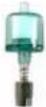 |
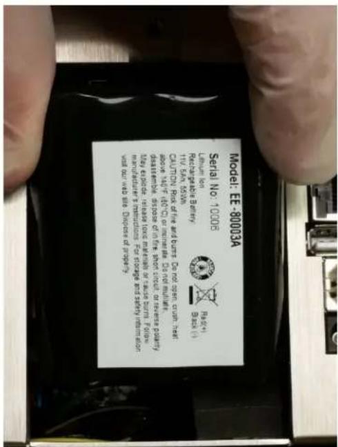
| Rechargeable Battery 55Wh | EE-80003A |  |
| Temperature / RH Probe 32-122°F (0-60°C) ±1°F (0.5°C), 15 - 90% ±2% | EE-80014A |  |
| Power Supply 15V ~2amp 100-240VAC (Select adapter -US, -EU, -UK or -CN) | EE-80081-XX | 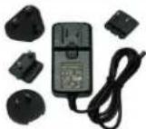 |
| USB Cable 6' (1.8m) | AS-99010 |  |
| Handheld User Manual and Data Download Software (USB Key) | MN-24001 |
1-7 Optional Accessories
| Description | Part Number | Image |
| Wireless 802.11 b/g Output with Internal Antenna | EE-80092 |  |
| Handheld Carrying Case | AS-99023 |  |
| External Battery Charger 55Wh | AS-99005A | 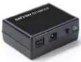 |
| Rechargeable Battery 55Wh | EE-80003A |  |
| External Thermal Printer with 2 rolls of paper | AS-99011 | 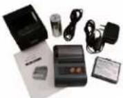 |
| External Thermal Printer Paper - 1 Roll | AS-99012 |  |
| External Thermal Printer Cleanroom Paper - 10 Pack | AS-99013 |  |
| External Thermal Printer Spare Battery | AS-99014 |  |
| Isoprobe Threaded 0.1 CFM (2.83 LPM) Stainless Steel | PS-12070 | [322DH] |
| Isoprobe Barbed 0.1 CFM (2.83 LPM) Stainless Steel | PS-12022 | 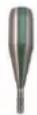 |
| 1/8" Inlet Barbed Fitting Stainless Steel | PS-12005 | 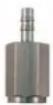 |
| Sample Tubing 1/4" OD (1/8" ID) per foot | AS-99018 | [4VXT] |
| Handheld User Manual (Printed) | MN-24003P | [4DWY] |
| 7000 Series Validation Manual | MN-24002 | [86CT] |
| Certificate of Origin | MN-24000 | [47YS] |
1-8 Product Views
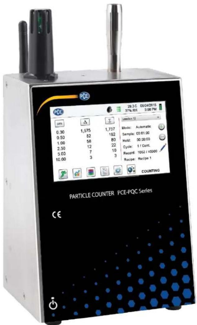
text_image
PCE 29.3 C 08/04/2015 37% RH 3:08 PM PCE 29.3 C 08/04/2015 37% RH 3:08 PM μm Δ Σ Lemon 12 Mode: Automatic Sample: 00:01:00 Hold: 00:00:00 Cycle: 1 / Cont. Record: 1062 / 45000 Recipe: Recipe 1 COUNTING PARTICLE COUNTER PCE-PQC Series CE
text_image
Front View Temperature & RH Probe Isoprobe 4.3" Color Touchscreen Display PAPITICLE COUNTER PCE-PQC Series Power Switch
text_image
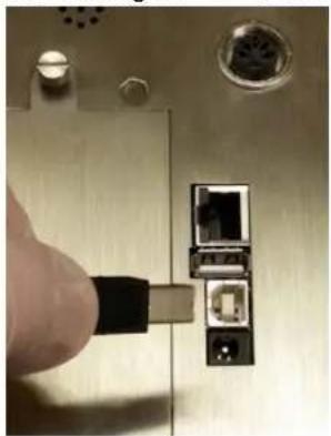
Rear View Wi-Fi Antenna (optional) Exhaust Port RS485/RS232 Connection (optional) Communications connectors - Ethernet - USB Host - USB Client Power Supply Connection Battery CompartmentConnecting Ethernet Cable

natural_image
Close-up of a hand inserting a RJ46 network into a wall-mounted device (no visible text or symbols)Connecting USB - B Client
natural_image
Close-up of a hand inserting a USB into a socket on a metal electronic device (no visible text or symbols)Connecting USB - A Host

natural_image
Close-up of a hand inserting a USB into a wall-mounted device (no text or symbols visible)2-1 Unpacking and Inspecting the Instrument
Careful consideration was given to our packing material to ensure that the PCE Instruments particle counters will reach you in perfect condition. If the instrument has been subject to excessive handling during shipping, there may be visible damage to the shipping carton. In the event of damage, keep the shipping container and packing material for the carrier's inspection. Carefully unpack the instrument from its shipping container and inspect the contents for damaged or missing items. If the instrument appears damaged or something is missing, contact the carrier and PCE Instruments immediately. Please save the container and packing material in case you have to return the instrument.
2-2 Registering Your Product
All PCE Instruments' particle counters are automatically registered upon sale for the warranty period and tracked by Serial number.
2-3 Contacting PCE Instruments
To order accessories, receive technical assistance, report damaged or missing items from your shipment, or get contact information for your nearest PCE Instruments authorized reseller, call - Germany: +49 2903 976990 / USA: +1 (561) 320-9162
2-4 Storing and Shipping the Instrument
This instrument utilizes a high quality advanced Lithium Ion Power Cell. This must be removed from the device prior to shipping the unit. If the instrument needs to be packed and shipped for annual calibration or service, it is recommended to use the original packing materials. If they are not available, please insure that the instrument is packaged in a box that is sturdy and that the instrument is well protected with proper packing materials to cushion and protect it from harm during transit.
To store the instrument, place it in its optional case or in a box, under cover, in an environment as stated in the Specifications in Section 1-5.
2-5 Power Considerations and Connecting to AC Power
The PCE Instruments particle counter comes with a power adapter line cord for AC powered operation and battery charging. The power adapter is designed to operate with line voltage from around the world. The correct plug adapter must be used to match your local AC power adapter standard. If the instrument power adapter does not have the proper plug configuration, please contact PCE Instruments or an authorized reseller for service.
To install the country specific plug adapter, simply slide the adapter into the power supply as shown.
text_image
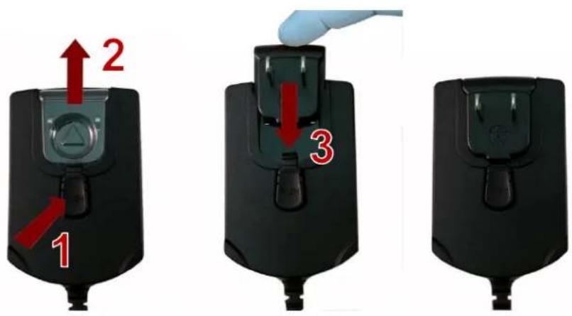
1 2 32-6 Installing Batteries

CAUTION - The PCE Instruments' rechargeable battery is an intelligent battery pack with onboard processing to ensure proper cell loading and other functions that support the advanced power management features of this instrument. To ensure a long life for the batteries and for adherence to any local regulatory guidelines for the use, storage and disposal of Lithium Ion batteries, please follow these instructions carefully.

WARNING – Do not plug in or charge the PCE Instruments Lithium-Ion rechargeable battery with any other power source other than the approved PCE Instruments Rechargeable External Battery Charger Model SPCAS-99005A or the PCE Instruments Power Supply Model SPCEE-80128. Using any other charger can cause fire, shock or serious injury.


Caution: Dispose of PCE Instruments Lithium-Ion batteries at an approved local battery recycling center.
Install the PCE Instruments Battery pack into the instrument using the following steps:
text_image
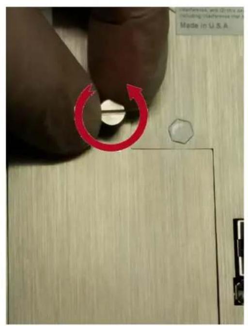
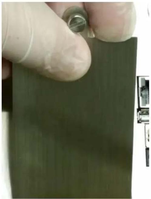
Made in U.S.A.Step 1 – Loosen the Knurled Thumb-turn screw
natural_image
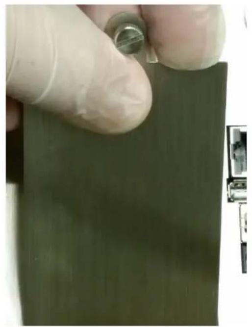
Close-up of a gloved hand holding a small metallic object over a green rectangular surface, with no visible text or symbols.Step 2 – Remove Battery Compartment Door
natural_image
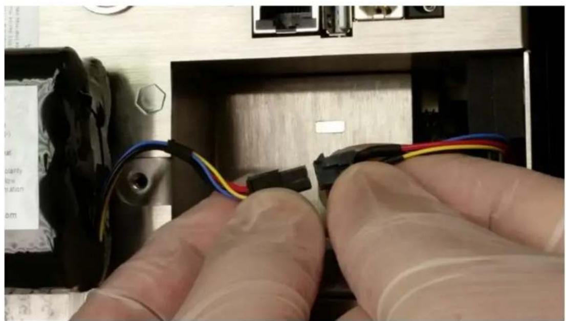
Close-up of hands installing a cable with multicolored wires inside an electronic device (no visible text or symbols)Step 3 – Insert battery connector plug into matching socket on matching wired connector in the battery compartment.
NOTE: Leads line up color for color and socket has a keyed fit. Carefully tuck the wires neatly back in to the recess in the rear of the battery compartment.
text_image
Model: EE-80003A Serial No. 10.006 Lipum Ion Rechargeable Battery TJU S/N, 50kN CAUTION: Risk of life and burns. Do not open account test above VOLT (40°C) or smaller. Do not multiStack. disassentate, dispose of in fire, short circuit or reverse battery May expide, release toxic membrane or cause burn. Follow manufacturer's instructions. For storage and safety information will our web life. Disposes of property.Step 5 – Carefully push battery into the compartment
natural_image
Close-up of a gloved hand holding a small metallic object over a green rectangular surface, with a small mechanical component visible on the right (no text or symbols)Step 6 – Replace battery compartment door and tighten thumb-turn knurled screw
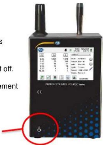
2-7 Turning the Unit On
The External one-touch power button on the lower right bottom front corner of the instrument will power the instrument on and off and will turn sampling on and off.
Pressing the button turns the instrument on.
Pressing the button momentarily starts the pump and begins sampling.
Pressing the one-touch button again for 1 second stops sampling.
Holding the button for 2.5 seconds turns the instrument off.
The unit can also be turned off from the power management screen.
Power Button
text_image
Paddle Counter PCE-PDC Series CE2-8 Power and Charging Status LED (on power button)
Power and charging status is indicated externally on the instrument in the middle of the one-touch power button. The indication provides information on the charging rates and status (shown on right).
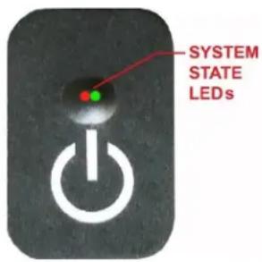
text_image
SYSTEM STATE LEDsUnit plugged into AC (instrument screen on or off)
Charging: Red LED on
Charging Complete: Green LED on
Unit not plugged into AC (instrument screen on)
Battery Charge <10%: Red LED blinks every 3 seconds
Unit not plugged into AC (instrument screen off)
All LED's off
3-1 Control and Menu Icons (ALL MODELS)


20.2 C 35% RH
2015/01/15 12:30:01 PM
| Function Name | Location/Screen | Description of Function |
| PCE logo Icon | Home Screen | Press the logo and the product information screen will appear displaying your model number, serial number, manufacture date, last calibration date, next calibration due date, and number of channels activated on the unit. Press the Back Arrow icon on bottom left corner of the display to return to Home screen. |
| Speaker Icon | Home Screen | Press the speaker icon to adjust volume using a pop-up slider bar. Press the cross bar on slider and move up and down for volume control. Icon will have red prohibited symbol when sound is turned off or muted. |
| Temperature & RH Indicator | Home Screen | Press the temperature and RH value indicator, to open a larger screen that displays Temperature, Relative Humidity, and the current Barometric Pressure. Press the Back Arrow icon on bottom left corner of the display to return to Home screen. |
| Time and Date Indicator | Home Screen | Press the time and date to change the current time and date. |


| Function Name | Location/Screen | Description of Function |
| Power Management Icon | Home Screen | Press the battery/power adapter indicator to display the battery power management screen, as well as the current battery status. |
| USB Icon | Home Screen | If a USB drive is connected, the USB Icon will appear. Press the USB Icon to save the current record to the USB drive. |
| Printer Indicator | Home Screen | If the PCE Instruments Printer is connected to USB Port, press the Printer Icon to print the current record. |
| System Warning Indicator | Home Screen | When the System Warning Indication Icon appears, press to display additional information. Please contact PCE Instruments technical service for assistance should the Icon remain visible. |
| Alarm Indicator | Home Screen | Visual indication that the instrument has exceeded the user-defined thresholds. Press icon to silence the alarm. |
| Run Icon | Home Screen | Press the Run icon to start sampling. Once pressed the Run icon will be replaced by the Stop icon. |
| Stop Icon | Home Screen | Press the Stop icon to stop the instrument from sampling. |
| Display Mode Icon | Home Screen | Press the Display Mode icon to switch between the Main Screen, Real-Time Meter, Graphing, and PM screen (must enable Mass Mode by going to Settings, then Channel Management for PM Screen). |
| Recorded Data Icon | Home Screen | Press the Recorded Data icon to display the saved data records page. All saved records can be accessed from this screen. |


Location 2
Mode: Automatic
Sample: 00:01:00
Hold: 00:02:00
Cycle: 1 / 3
| Function Name | Location/Screen | Description of Function |
| Reports Icon | Home Screen | Press the Reports icon to display ISO 14644-1, EU-GMP Annex 1, or Federal Standard 209E. |
| Particle Icon | Home Screen | Press the Particle icon to change the indicated values from particle count to count per cubic meter, count per cubic foot, or particle mass concentration (must enable Mass Mode by going to Settings, then Channel Management to display particle mass concentration). |
| Differential Mode Icon | Home Screen | Press the Differential Mode icon to toggle the differential data values on and off. |
| Cumulative Mode Icon | Home Screen | Press the Cumulative Mode icon to toggle the differential data values on and off. |
| Location Menu Icon | Home Screen | Press the Location Menu icon to display the Location and Recipe set-up page. This feature allows for the input of up to 1,000 locations and up to 50 unique user-defined recipes. |
| Mode Indicator | Home Screen | The Mode Indicator displays the current mode of operation for the instrument. Modes include automatic, manual, and continuous. |
| Sample Indicator | Home Screen | The Sample Time indicator displays the current sample time duration (Hours:Minutes:Seconds). This value will count down from the set value for the sample time, displaying the amount of time left in the current sample (go to Settings, then Sampling Setup to change Sample Timing). |
| Hold Indicator | Home Screen | The Hold Time indicator displays the current hold time as an interval between samples. The maximum hold time is 99 hours, 59 minutes and 59 seconds (go to Settings, then Sampling Setup to change Hold Time). |
| Cycle Indicator | Home Screen | The Cycle indicator displays the number of count samples that will be taken at a location in automatic mode. The maximum number of possible cycles is 9,999. The value is displayed as the sample number vs. the total number of samples to be completed in this cycle (go to Settings, then Sampling Setup to change Cycles). |
Record: 1 / 45000


| Function Name | Location/Screen | Description of Function |
| Record Indicator | Home Screen | The Record indicator displays the total number of sampling records saved in the instrument. The instrument is capable of storing 45,000 records in a rotating buffer. |
| Settings Menu Icon | Home Screen | Press the Settings Menu icon to open the Settings Screen. All aspects of the instrument's set-up can be managed from the icon driven sub-menus. |
| Annotation Icon | Home Screen | Press the Annotation icon to notate up to 32 characters for each record. This action can be performed during sampling or after a sample has been taken. The green pencil indicates an annotation exists for any record (go to Settings, then Configuration to enable Annotations). |
| Plus and Minus Buttons | Home Screen | Press the Plus or Minus icons to scroll through 1,000 possible locations that can be saved and uniquely identified in the Locations setup screen. Locations can have set recipes assigned to them in advance for ease-of-use during sampling. |
| Flow & No Flow Indicator | Home Screen | The three horizontal arrows indicate that the pump is working and that the internal flow sensor is detecting the correct flow rate through the instrument. If a red line appears diagonally through the arrows, it is an indication of a flow error. |
| Back Arrow Icon | Various Screens | Press Back Arrow icon to return to the previous screen. |


4-1 Operational Flow Chart – Menu Map
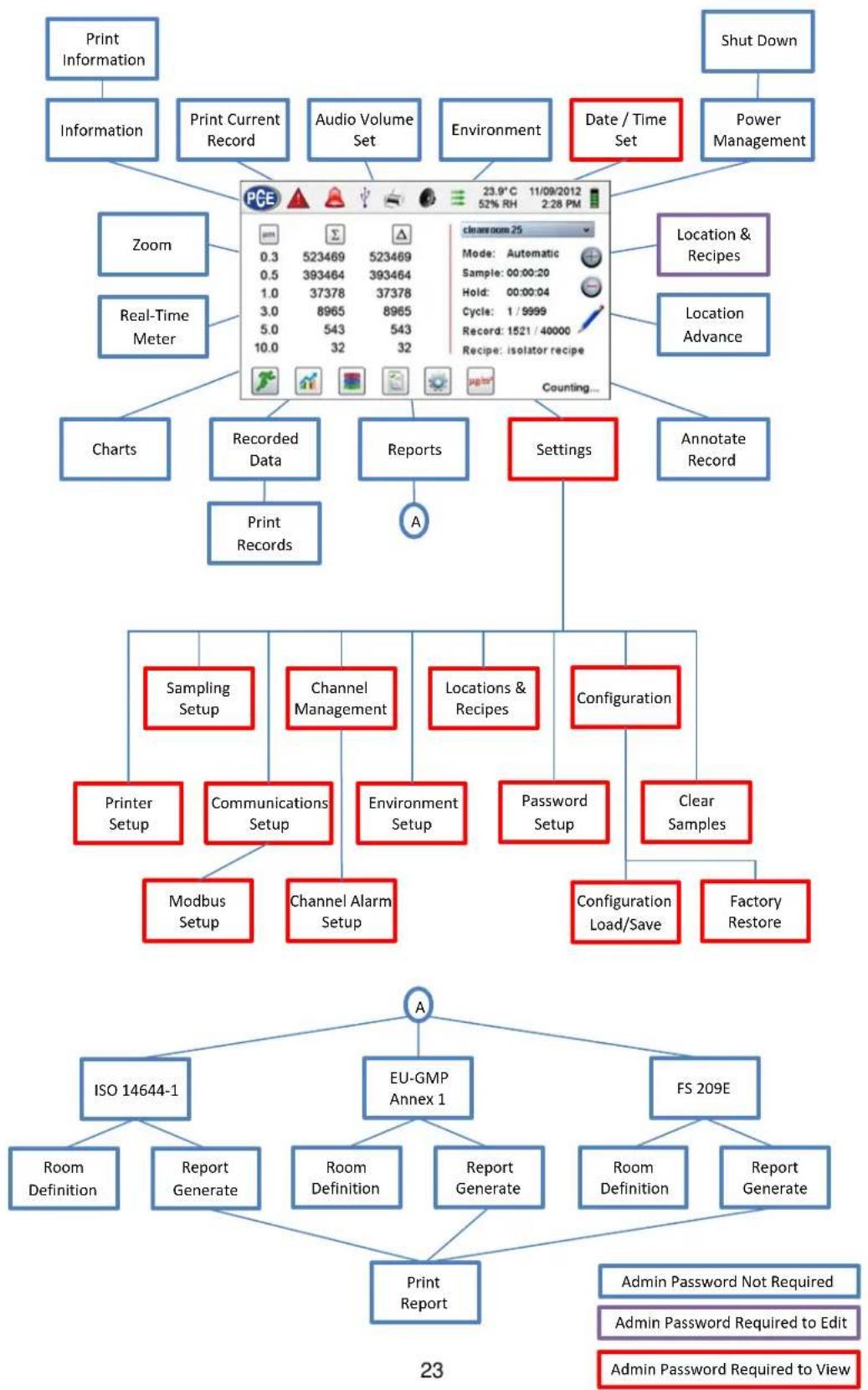
flowchart
graph TD
    A["Print Information"] --> B["Information"]
    B --> C["Zoom"]
    C --> D["Real-Time Meter"]
    D --> E["Charts"]
    E --> F["Recorded Data"]
    F --> G["Print Records"]
    H["Shut Down"] --> I["Power Management"]
    J["Location & Recipes"] --> K["Location Advance"]
    L["Settings"] --> M["Configuration"]
    N["Serials Setup"] --> O["Printer Setup"]
    N --> P["Communications Setup"]
    N --> Q["Environment Setup"]
    N --> R["Password Setup"]
    N --> S["Clear Samples"]
    T["Modbus Setup"] --> U["Channel Alarm Setup"]
    V["ISO 14644-1"] --> W["Report Generate"]
    X["EU-GMP Annex 1"] --> Y["Report Generate"]
    Z["FS 209E"] --> AA["Report Generate"]
    AB["Print Report"] --> AC["Report Generate"]
    AD["A"] --> AE["Configuration Load/Save"]
    AE --> AF["Factory Restore"]
    AG["A"] --> AH["Form Description"]
5-1 Operation – Initial Power Up – First Time Use
After the Particle Counter turns on for the first time, a window will appear stating "Time of Day Clock Not Set". Press OK to Set Clock.
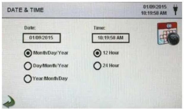
text_image
DATE & TIME 01/09/2015 10:19:58 AM Date: 01/09/2015 Time: 10:19:58 AM Month/Day/Year 12 Hour Day/Month/Year 24 Hour Year/Month/DayDate Format Select Button
Choose format for Month/Day/Year, Day/Month/Year, or Year/Month/Day by selecting the corresponding button on the screen.
Numeric Keypad
Press Date within the window and a numeric keypad will appear to change the date. To change the values, use the < or > to move cursor. When complete press OK button.
Time Format Select Button
Choose 12 hour or 24 hour clock indication by selecting the corresponding button on the touchscreen.
Numeric Keypad
Press Time within the window and a numeric keypad will appear to change time. Use 24 hour clock format for time entry to properly indicate AM or PM. To change the values, use the < or > to move cursor. When complete press OK button. Time will display AM or PM or 24 hour format based on the selection.

Back Arrow Icon
Press Back Arrow icon to return to the previous screen.
5-2 Display
Press any blank space on the screen to zoom in or out on the Home page.

text_image
PGE 02/01/2018 08:06:25 AM μm Δ Σ Location 1 0.30 3,437 3,761 0.50 251 324 1.00 44 73 2.50 20 29 5.00 6 10.00 3 3 Mode: Automatic Sample: 00:00:10 Hold: 00:00:00 Record: 1170 / 45000 STOPPEDStandard View

text_image
PCE 0.30 0.50 1.00 2.50 5.00 10.00 Location: Location 1 3,437 251 44 20 6 3 3,761 324 73 29 8 3 STOPPED 02/01/2018 DEC16:30 AMZoomed View
5-3 Taking a Sample
Main Sampling Home Screen
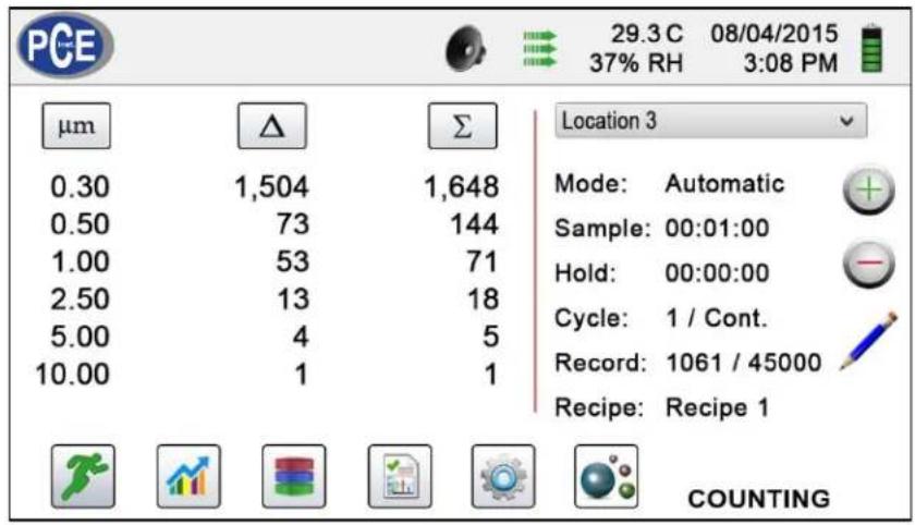
text_image
PCE 29.3 C 08/04/2015 37% RH 3:08 PM μm Δ Σ 0.30 1,504 1,648 0.50 73 144 1.00 53 71 2.50 13 18 5.00 4 5 10.00 1 1 Location 3 Mode: Automatic Sample: 00:01:00 Hold: 00:00:00 Cycle: 1 / Cont. Record: 1061 / 45000 Recipe: Recipe 1 COUNTING

Taking a Sample
Using the one touch power/sample button or the Run icon on the display begins the sample.
To take a sample, press the one touch power/sample button or the Run icon on the screen. This will begin the sample according to the sampling setup parameters displayed on the right side of the Home screen (go to Settings, then Sampling Setup to change Sample Timing).


Stopping the Sample
Using the one touch power/sample button or the Stop icon on the display stops the sample
To stop a sample, press the one touch power/sample button or the Stop icon on the screen.


Data Unit of Measure Selection
Press the Particle icon to change the indicated values from particle count to count per cubic meter, count per cubic foot, or particle mass concentration (must enable Mass Mode by going to Settings, then Channel Management to display particle mass concentration).
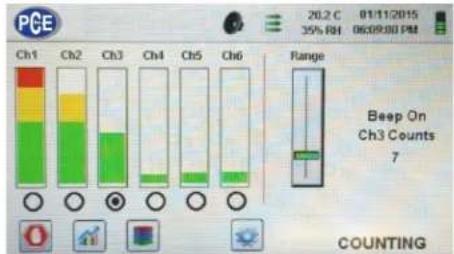
5-4 Real-Time Meter, Graphing, and Environmental Screens

The instrument will display a bar graph visualization that rises and falls with the increase of pulses counted per second, per channel. This can be used to pinpoint the source of particles within an area. The closer the instrument is to the source, the higher the indication appears on the bar graph.

text_image
PCE 20.2 C 01/11/2015 35% PdI 06:00:00 PM Ch1 Ch2 Ch3 Ch4 Ch5 Ch6 Range Beep On Ch3 Counts 7 COUNTINGChannel 3 selected and signal at maximum value
text_image
PGE 20.2 C 01/11/2015 35% RH 06:09:00 PM Ch1 Ch2 Ch3 Ch4 Ch5 Ch6 Range Beep On Ch3 Counts 7 COUNTINGRange slider lowered to reduce Channel 3 value
Real-Time Meter Operation


Start/Stop Sampling while on Real-Time Meter or Graphing Screen
The Sampling can be started or stopped from these screens using the Run or Stop icons or by using the one touch button.

Channel Select – Radio Button
Select the channel size that is the focus of the particles being investigated by clicking on the radio select button below each channel. The channel selected also represents the data being displayed in pulses per second on the Graphing screen.
Range

Range – Sensitivity Adjustment Slider
Press and slide the Range slider bar up towards the top of the slider to increase sensitivity and down towards the bottom of the slider to decrease sensitivity. As the instrument gets closer to the particle source the visual signal can increase and hit 100% of the indicated scale long before the actual source of the contamination is found. By moving the Range slider bar down, the sensitivity is reduced, and the indication is scaled down. This action can be repeated until the source is identified.

Switching between Main Screen, Real-Time Meter, Graphing, and Environmental Screens
Press the Real-Time Meter icon to switch between the Main screen, Real-Time Meter, Graphing, and Environmental screens (must enable Mass Mode by going to Settings, then Channel Management to display Environmental screen).
NOTE: Go to Settings, then to Screens to select which screens will be available.
Real-Time Graph Operation
If the Graph function is chosen, this feature graphically displays the pulses per second, making the graph's historical information useful in point source detection.
Real-Time Graph

line
| Time - 2 seconds per division | CH3 Particles / Sec | | ----------------------------- | ------------------- | | 04/17/2015 | 8000 |Environmental Screen
This screen displays specific PM size, temperature and humidity.

text_image
PCE 27.31 C 08/04/2015 37% RH 3:08 PM Pressing the PM value accesses the Select PM To Display screen (shown below) 5 PM 2.5 µg/m³ 27.3 Temp °C 37 RH % COUNTINGEnvironmental Screen size select
Select the PM size channel to be displayed
Press Back Arrow to return to the previous screen.
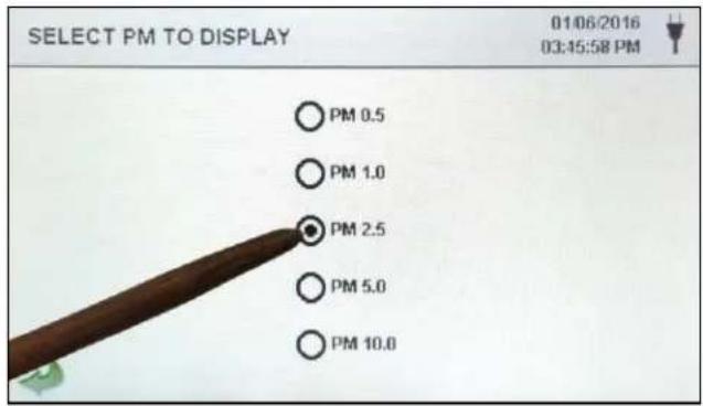
text_image
SELECT PM TO DISPLAY 01/06/2016 03:45:58 PM PM 0.5 PM 1.0 PM 2.5 PM 5.0 PM 10.0Home Screen Mass Concentration
g/m^3 is displayed in the first column for that particle size up to the next size as a value
PM is the sum of all previous channels not including that channel size value

text_image
PGE 66.9 F 01/06/2016 23% RH 03:44:22 PM µm µg/m³ PM Location 1 0.30 0.83 ---- Mode: Automatic 0.50 0.64 0.83 Sample: 00:14:57 1.00 1.37 1.47 Hold: 00:00:00 2.50 10.35 2.84 Cycle: 1 / Cont. 5.00 25.20 13.19 Record: 234 / 45000 10.00 57.61 38.39 TPM: 96.00 µg/m³ COUNTING5-5 Recorded Data

The instrument stores up to 45,000 records that can be accessed by selecting the recorded data icon. The Recorded data page uses a horizontal slider bar for scrolling left and right through all records. Press white arrows for fine control in locating a specific record. Press the slider button with the stylus and drag left or right to navigate through large amounts of records quickly.
NOTE: After the 45,000th sample is recorded, the software deletes one block of 250 records. After the block is deleted the next record number will become 44,751. The instrument will then store data to record 45,000 before repeating this process. Each block removed is from the oldest record first, following a first in / first out method.
Recorded Data Screen

text_image
RECORDED DATA 01/14/2015 11:59:24 AM μm Δm³ Σm³ Location 1 0.30 0 0 Date: 01/07/2015 0.50 0 0 Time: 05:59:46 PM 1.00 0 0 Sample: 00:01:00.191 3.00 0 0 Volume: 0.100000 ft^3 5.00 0 0 Laser: OK 10.00 0 0 Flow: OK Temp: 75°F RH: 46% RECORD: 1/28

Print or Save the Current Record being displayed
If a Printer or USB thumb drive is attached to the instrument, the current record on the Recorded Data Screen can be downloaded or printed by pressing the corresponding Printer or USB icon.
All displayed channel values can be turned off or back on from the recorded sample record by toggling the mode icons.

Data Units
Data Units can be changed to the corresponding calculated values by pressing the Particle icon. Press the icon to change between particle count, count per cubic meter, count per cubic foot, or g/m^3 (if enabled).

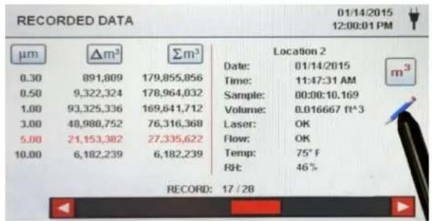
Adding Annotations to Recorded Data
Press the Annotation icon to notate up to 32 characters for each record. This action can be performed during sampling or after a sample has been taken. The green pencil indicates an annotation exists for any record (go to Settings, then Configuration to enable Annotations).
text_image
RECORDED DATA 01/14/2015 12:00:01 PM μm Δm³ Σm³ Location 2 0.30 891,809 179,855,856 Date: 01/14/2015 0.50 9,322,324 178,964,032 Time: 11:47:31 AM 1.00 93,325,336 169,641,712 Sample: 00:00:10.169 3.00 48,980,752 76,316,368 Volume: 0.016667 ft^3 5.00 21,153,382 27,335,622 Laser: OK 10.00 6,182,239 6,182,239 Flow: OK Temp: 75°F Rt: 46% RECORD: 17 / 28Annotations Keyboard

text_image
EDIT ANNOTATION FOR RECORD 17 door opened during sample q w e r t y u i o p a s d f g h j k l ↑ z x c v b n m ←x ESC ?123 , . OK
Saved Annotation Icon
The green pencil over a document icon denotes that an annotation exists on that record. The annotation can be accessed, edited or deleted.
Caps Lock, ?123, and Delete Keys
Pressing the Shift Key will activate or deactivate the Caps Lock function. Pressing the ?123 Key will toggle the use of numbers and symbols. Pressing the Backspace Key will delete all text entered on the text line.
Statistics
Pressing the Statistics icon will provide an onscreen display of the minimum, maximum, and average values for the records selected. This function is disabled if a printer or USB stick is connected to the instrument.
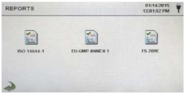
5-6 Reports

Report Functions
text_image
REPORTS 01/14/2015 12:01:52 PM ISO 14644-1 EU-GMP ANNEX 1 FS 209EISO 14644-1
Press the ISO 14644-1 icon to generate a report based on the parameters and guidelines of the ISO standard.
EU-GMP Annex-1
Press the EU-GMP ANNEX 1 icon to generate a report based on the parameters and guidelines of the EU-GMP standard.
FS 209E
Press the FS 209E icon to generate a report based on the parameters and guidelines of the US Federal standard 209E.
Room parameters can be defined by pressing the Room Definition button. To generate a report, select the Generate button. This creates a report document that can be saved to an external thumb drive, or printed to a connected printer.
Press the Create Report button for 5 seconds to display a sample report with the current test records. These records will be added to the recorded data so the values and information can be reviewed prior to completing the report and saving to an external source.
Generate
Create Report
Press the Generate button to display the Report Generation screen
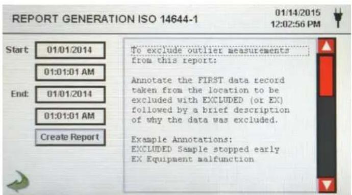
text_image
REPORT GENERATION ISO 14644-1 01/14/2015 12:02:56 PM Start 01/01/2014 01:01:01 AM End: 01/01/2014 01:01:01 AM Create Report To exclude outlier measurements from this report: Annotate the FIRST data record taken from the location to be excluded with EXCLUDED (or EX) followed by a brief description of why the data was excluded. Example Annotations: EXCLUDED Sample stopped early EX Equipment malfunctionCreate Report
Press the Start and End Windows to enter the Start and End dates and times. Press the Create Report button to generate the report. If the values of the count or sampling set-up are incorrect, the report will indicate the errors prior to the report being generated.
To exclude an outlier measurement from the report, go to Recorded Data, find the specific recorded data to be excluded and annotate the record by writing "EXCLUDED" or "EX". A brief description must be added after the "EXCLUDED" or "EX" explaining why the data is being excluded. Example Annotations: "EXCLUDED Sample Stopped Early" or "EX Equipment Failure"
Room Definition
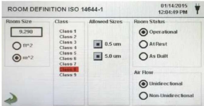
text_image
ROOM DEFINITION ISO 14644-1 01/14/2015 12:04:49 PM Room Size 9.290 Class Class 1 Class 2 Class 3 Class 4 Class 5 Class 6 Class 7 Class 8 Class 9 Allowed Sizes 0.5 um 5.0 um Room Status Operational At Rest As Built Air Flow Unidirectional Non-UnidirectionalEach Report has a Room Definition page to input data that defines the output of the report. The inputs include Room Size, Class, Allowed (Channel) Sizes, Room Status and Air Flow.
Sample Report Screen
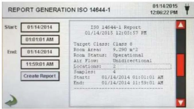
text_image
REPORT GENERATION ISO 14644-1 01/14/2015 12:06:22 PM Start: 01/14/2014 01:01:01 AM End: 01/14/2014 11:59:01 AM Create Report ISO 14644-1 Report 01/14/2015 12:05:57 PM Target Class: Class 8 Room Area: 9.290 m^2 Room Status: Operational Air Flow: Unidirectional Locations: 2 Samples: 4 Start: 01/14/2014 01:01:01 AM End: 01/14/2014 11:59:01 AMSample Report (Printed)
| ISO 14644-1 Report01/16/2015 06:54:08 AM | |
| Target Class: Class 5Room Area: 80.000 m^2Room Status: OperationalAir Flow: UnidirectionalLocations: 9Samples: 11Start: 01/16/2015 06:53:01 AMEnd: 01/16/2015 06:53:09 AM | |
| Class Class 5 (at 0.3) | PASS |
| Class Limit: 10,200.00 P/m^3Min Sample Vol: 0.00283 m^3 | |
| Grand Mean: 6,349.21Std Dev: 2,154.42Std Error: 718.1495% UCL: 7,684.94 | |
| Location Avg P/m^314644 Test Loc 1 8,750.014644 Test Loc 2 6,607.114644 Test Loc 3 2,107.114644 Test Loc 4 3,785.714644 Test Loc 5 5.857.1 | |
| Class Class 5 (at 0.5) | PASS |
| Class Limit: 3,520.00 P/m^3Min Sample Vol: 0.00568 m^3 | |
| Grand Mean: 706.35Std Dev: 381.65Std Error: 127.2295% UCL: 942.97 | |
| Location Avg P/m^314644 Test Loc 1 750.014644 Test Loc 2 857.114644 Test Loc 3 0.014644 Test Loc 4 250.014644 Test Loc 5 785.7 | |
| Unit Serial #: 1000Last Cal: 05/15/2014---- End of Report ---- | |

Printing or Saving a Report
With a thumb drive or printer connected, press the Printer icon to print a report, or press the USB icon to save a report.
NOTE: A thumb drive or printer must be connected to the instrument to display these icons.
6-1 Settings

Settings Screen Press the Settings Menu icon to open the Settings Screen. All aspects of the instrument's set-up can be managed from the icon driven sub-menus. When the administrator password is in use, this screen is not available and may only be accessed and settings modified by the administrator.
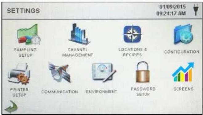
text_image
SETTINGS 01/09/2015 09:24:17 AM SAMPLING SETUP CHANNEL MANAGEMENT LOCATIONS & RECIPIES CONFIGURATION PRINTER SETUP COMMUNICATION ENVIRONMENT PASSWORD SETUP SCREENs6-2 Sampling Setup

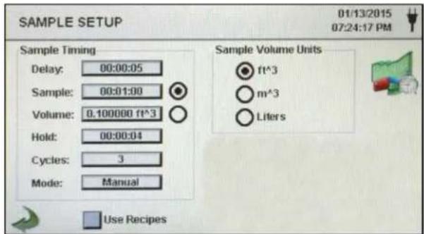
Sampling Setup Screen Press the Sampling icon to display the Sample Setup screen.
text_image
SAMPLE SETUP 01/13/2015 07:24:17 PM Sample Timing Delay: 00:00:05 Sample: 00:01:00 Volume: 0.100000 ft^3 Hold: 00:00:04 Cycles: 3 Mode: Manual Sample Volume Units ● ft^3 ○ m^3 ○ Liters Use RecipesDelay
Press the Delay window to open the Enter Time screen. To select the value to change, use the < or > to move cursor. The entry is made in Hours:Minutes:Seconds (HH:MM:SS). The maximum Delay time is 99 hours, 59 minutes and 59 seconds. When complete press OK button.
NOTE: This allows the operator to leave an area before sampling begins.

Clear All Samples
Press Clear Samples icon to open the Clear Samples window. All records on the instrument can be cleared with this function. NOTE: This action is not reversible and all data will be cleared by pressing the Yes button.

text_image
Clear Samples Are you sure you wish to clear all samples? Yes No6-3 Channel Management

This screen provides control of many rich features such as enabling or disabling channels, setting custom channel sizes, enabling or disabling alarms by channel, and the setting of the alarm thresholds. The mass concentration mode may also be activated to allow entry of particle density and refractive index values by channel.
Channel Management Screen

text_image
CHANNEL MANAGEMENT 01/14/2015 12:31:18 PM Enable Channel: Size pmc: Enable Alarm Threshold: Density g/ml: Refractive Index: Ch 1 0.30 5000000 Ch 2 0.50 3520000 Ch 3 1.00 832000 Ch 4 3.00 3000 Ch 5 5.00 29300 Ch 6 10.00 350 Use Recipes Alarm On Σft³ Mass ModeSample Press the Sample window to open the Enter Time screen. To select the value to change, use the < or > to move cursor. The entry is made in Hours:Minutes:Seconds (HH:MM:SS). The maximum Sample time is 99 hours, 59 minutes and 59 seconds. When complete press OK button.
Volume Press the Volume window to open the Enter Sample Volume screen. To select the value to change, use the < or > to move cursor. The volume value entered will control the length of time per sample to achieve the desired sample volume.
Sample or Volume Selection Buttons Selecting the Sample button will cause the sample to be time based. Selecting the Volume button will cause the sample to be based on the volume of air to be measured.
Hold Press the Hold window to open the Enter Time screen. This controls the amount of time the instrument will hold between samples in automatic mode. To select the value to change, use the < or > to move cursor. The entry is made in Hours:Minutes:Seconds (HH:MM:SS). The maximum Hold time is 99 hours, 59 minutes and 59 seconds. When complete press OK button.
Cycles Press the Cycles window to open the Enter Cycles screen. This controls the number of sampling cycles to be taken at a specific location when the unit is in automatic mode. To select the value to change, use the < or > to move cursor. When complete press OK button.
NOTE: Enter (0000) to activate Continuous Sampling Mode.
Mode Press the Mode window to open the Select Sample Mode screen. Select Automatic or Manual. When complete press OK button.
Sample Volume Units Select Cubic Feet (ft^3), Cubic Meters (m^3) or Liters.
Use Recipes Button The Use Recipes button activates Recipes on the Select Location & Recipe screen. Recipes associated with locations will be utilized in place of the general settings from the Sample Setup screen.

Back Arrow Icon Press the Back Arrow icon to return to the previous screen.
Enable Channel
Each channel can be turned on or off by pressing the corresponding radio button. When the channel is turned off all values related to that channel are ignored and will not be displayed or recorded.
Size μm
Press the Size m window to open the Enter Channel Size screen. This controls the particle size measured and recorded for the selected channel. This feature is also known as variable binning, and is ideal for focusing on specific particle sizes. To select the value to change, use the < or > to move cursor. When complete press OK button.
Enable Alarms
Each channel can have an alarm enabled or disabled by pressing if the User Recipes button is not selected. If enabled, Press the Alarm Threshold window to open the Enter Alarm Threshold screen. To select the value to change, use the < or > to move cursor. When complete press OK button.

Alarm On
Press the Alarm On button to open the Channel Alarm Setup screen. Select (Differential Count), ft^3 (Differential Cubic Feet), m^3 (Differential Cubic Meter), (Cumulative Count), ft^3 (Cumulative Cubic Feet Count), m^3 (Cumulative Cubic Meter Count), PM ( g/m^3 ).
Mass Mode Settings
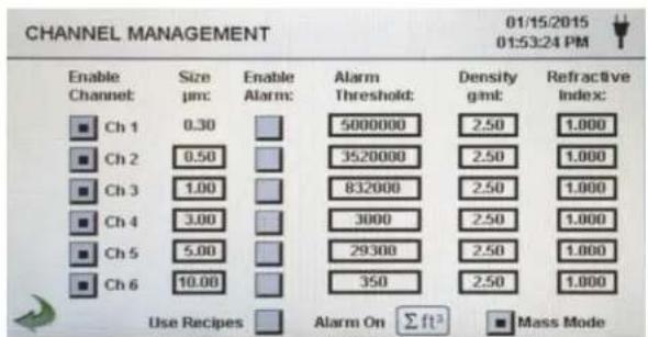
text_image
CHANNEL MANAGEMENT 01/15/2015 01:53:24 PM Enable Channel Size µm: Enable Alarm: Alarm Threshold: Density gmt: Refractive Index: Ch 1 0.30 5000000 2.50 1.000 Ch 2 0.50 3520000 2.50 1.000 Ch 3 1.00 832000 2.50 1.000 Ch 4 3.00 3000 2.50 1.000 Ch 5 5.00 29300 2.50 1.000 Ch 6 10.00 350 2.50 1.000 Use Recipes Alarm On Σft³ Mass Mode
Mass Mode
Mass Mode Enable
Press the Mass Mode button to enable Mass Mode. The instrument will now display particle count data as calculated particle mass concentration in weight/volume units. The international SI unit for mass is (kg/m ^3 ), which can be translated to micro grams per milliliter ( g/ml).
Density g/ml
Press the Density g/ml window to open the Enter Density Factor screen. To select the value to change, use the < or > to move cursor. When complete press OK button.
Refractive Index
Press the Refractive Index window to open the Enter Refractive Index screen. To select the value to change, use the < or > to move cursor. When complete press OK button.
Calculation of displayed Values on Main Screen for Mass Concentration Mode
| μg/m3IndicatedValues | When Mass Mode is selected and μg/m3is selected on the Main screen, the instrument is measuring in Mass Concentration Mode. The mass value for a channel size is the particle count between that channel and the next larger channel, calculated using the average particle size of the two channels. For example, the value in the 0.50 μm data field represents the mass of all particles counted between this channel and the next highest channel, calculated as the mass of a particle that is 0.75 μm. |
| Particle Mass Indicated Values | When Mass Concentration Mode is selected, g/m^3 is the measured value in the first column. The column labeled PM shows the total particle mass of particles that are less than the displayed channel size. For example, the value displayed in the PM column for the 2.5 m channel is the particle mass ( g/m^3 column) of all particles with a size less than 2.5 m , generally referred to as PM2.5. |
6-4 Locations & Recipes

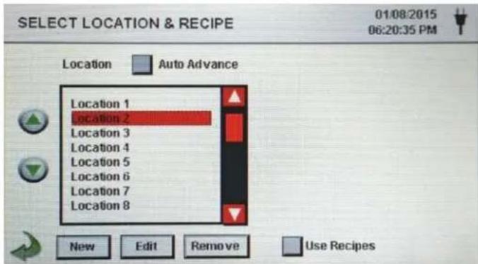
Press the Locations & Recipes icon to open the Select Location & Recipe screen. Up to 1,000 unique location names can be created. Pressing the User Recipes button allows the creation of location specific recipes which utilize preset sample Delay, Sample or Volume, Hold, Cycles, Mode and Channel Alarm.50 unique recipes can be created and assigned to any number of locations.
Select Location & Recipe Screen
text_image
SELECT LOCATION & RECIPE 01/08/2015 06:20:35 PM Location Auto Advance Location 1 location 2 location 3 location 4 location 5 location 6 location 7 location 8 New Edit Remove Use RecipesLocation Auto Advance
Select the Location Auto Advance button to auto advance to the next location.
Slider
The Select Location & Recipe screen uses a vertical slider bar for scrolling through all locations. Press white arrows for fine control. Press the slider button with the stylus and drag to navigate through large amounts of locations quickly.

 | Change Sequence of Locations | Press the silver and green up and down arrow buttons on the left side of the locations list to change the sequence of locations. |
 | New Location Entry | Press the New button to open the Enter Name For New Location screen. Use the keyboard to enter the name of the new location. Press OK to save the new location name or ESC to return to the previous screen. |
 | Edit Location | Press the Edit button to open the Enter Name For New Location screen. Use the keyboard to edit the name of the location. Press OK to save the new location name or ESC to return to the previous screen. |
 | Remove Location | Press the Remove button to delete the currently highlighted location. |
 Use Recipes Use Recipes | Use Recipes | Press the Use Recipes button to display the recipes settings. Select the Location in the Location box and the recipe in the Recipe box to assign the recipe to that location. The location can have one of 50 possible recipes assigned to it. |
 | ||
 | Edit Recipe for Selected Location | Press the Edit button on lower righthand side of the screen to open the Edit Recipes screen. |
 | New Recipe Entry | Press the New button to create a new recipe. The Enter Name for New Recipe screen will appear. Use the touchscreen keyboard to enter the name of the new recipe. Press OK to return to the previous screen. |
Use Recipes

Edit Recipe
Press the Edit button to modify the existing recipe highlighted on the Location list. Pressing this button will display the Enter New Name For Recipe screen. Use the touchscreen keyboard to modify the name of the existing recipe. Press OK to return to the previous screen.

Remove Recipe
Press the Remove button to delete the recipe that is highlighted on the Location list.
Used By Tab
The Used By window displays all locations currently set for the current recipe.
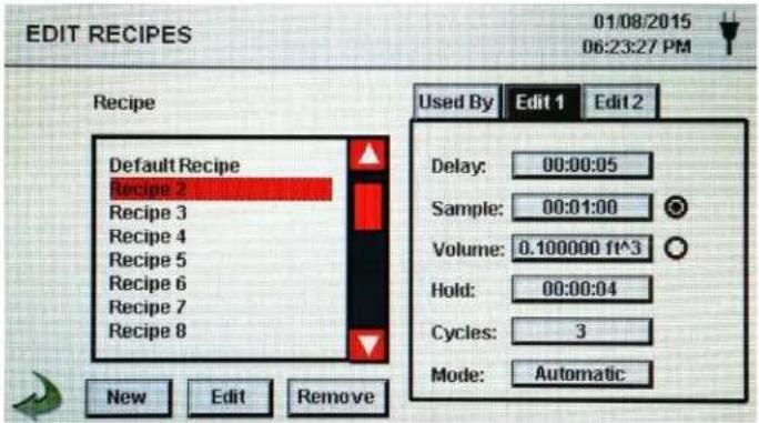
Edit 1 Tab
Press the Edit 1 tab to adjust the settings for Delay, Sample, Volume, Hold, Cycles, and Mode for the selected recipe.
text_image
EDIT RECIPES 01/08/2015 06:23:27 PM Recipe Default Recipe Recipe 2 Recipe 3 Recipe 4 Recipe 5 Recipe 6 Recipe 7 Recipe 8 New Edit Remove Used By Edit 1 Edit 2 Delay: 00:00:05 Sample: 00:01:00 Volume: 0.100000 ft^3 Hold: 00:00:04 Cycles: 3 Mode: AutomaticEdit 1 Delay
Press the Delay window to open the Enter Time screen. To select the value to change, use the < or > to move cursor. The entry is made in Hours:Minutes:Seconds (HH:MM:SS). The maximum Delay time is 99 hours, 59 minutes and 59 seconds. When complete press OK button.
NOTE: This allows the operator to leave an area before sampling begins.
Edit 1 Sample
Press the Sample window to open the Enter Time screen. To select the value to change, use the < or > to move cursor. The entry is made in Hours:Minutes:Seconds (HH:MM:SS). The maximum Sample time is 99 hours, 59 minutes and 59 seconds. When complete press OK button.
Edit 1 Volume
Press the Volume window to open the Enter Sample Volume screen. To select the value to change, use the < or > to move cursor. The volume value entered will control the length of time per sample to achieve the desired sample volume.
Sample or Volume Selection Buttons
Selecting the Sample button will cause the sample to be time based. Selecting the Volume button will cause the sample to be based on the volume of air to be measured.
Edit 1 Cycles
Press the Cycles window to open the Enter Cycles screen. This controls the number of sampling cycles to be taken at a specific location when the unit is in automatic mode. To select the value to change, use the < or > to move cursor. When complete press OK button.
NOTE: Enter (0000) to activate Continuous Sampling Mode.
Edit 1 Hold
Press the Hold window to open the Enter Time screen. This controls the amount of time the instrument will hold between samples in automatic mode. To select the value to change, use the < or > to move cursor. The entry is made in Hours:Minutes:Seconds (HH:MM:SS). The maximum Hold time is 99 hours, 59 minutes and 59 seconds. When complete press OK button.
Edit 1 Mode
Press the Mode window to open the Select Sample Mode screen. Select Automatic or Manual. When complete press OK button.
Edit 2 Tab
Press the Edit 2 tab to enable alarms for each channel size.

text_image
EDIT RECIPES 01/14/2015 12:33:01 PM Recipe Default Recipe Recipe 2 RE 100b Recipe 4 Recipe 5 Recipe 6 Recipe 7 Recipe 8 Used By Edit 1 Edit 2 Channel Alarm 0.3 0.5 1.0 3.0 5.0 10.0 New Edit RemoveBack Arrow Icon
Press the Back Arrow icon to return to the previous screen.

6-5 Configuration

Press the Configuration icon to select Language, Store Partial Samples, Alarm Acknowledgement, Enable Annotations, Number Format, Save Configuration to a USB thumb drive, and Factory Restore.
Configuration Screen

text_image
CONFIGURATION 01/15/2015 04:08:54 PM Language: English Store Partial Samples Alarm Acknowledge Enable Annotations Number Format 1,000.0 1,000.0 1,000.0 Factory RestoreLanguage
Select and highlight the language to be used with your device.
Store Partial Samples
Select the Store Partial Samples button to save values from a prematurely ended sampling. If this option is left unchecked, the instrument will ignore partial sampling events.
Alarm Acknowledge
Select the Alarm Acknowledge button and the visual alarm bell and the audible sounder will continue to sound until the alarm bell icon is pressed on the Main screen.
Enable Annotations
Select the Enable Annotations button to allow annotations to be entered for each sample record. These annotations will be included in downloaded record data.
Number Format
Select between 1,000.0, 1.000,0 or 1 000,0
Factory Restore
Press the Factory Restore button to open the Confirm Factory Restore screen. Select Settings to Restore and press the Confirm button.
USB Icon
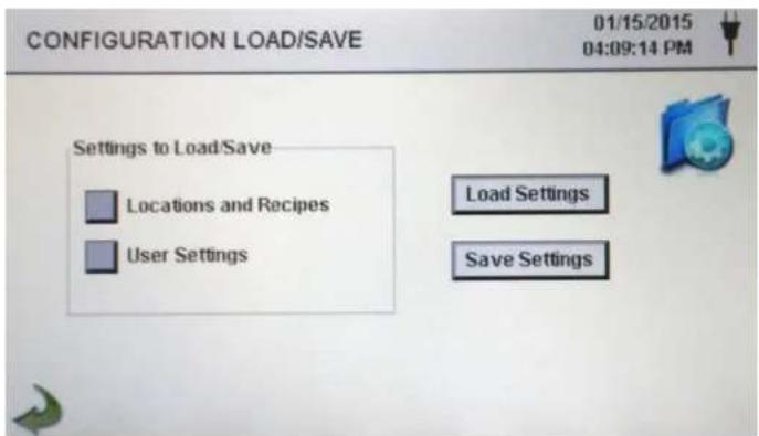
When a USB thumb drive is plugged into the USB host port, the USB icon will appear on the Configuration screen. Press the USB icon to open the Configuration Load/Save screen. Select Settings to Load/Save and press Load Settings or Save Settings.
NOTE: This feature can be used to load the instrument's configuration to any other PCE Instruments Particle Counter.
Configuration Load/Save Screen
text_image
CONFIGURATION LOAD/SAVE 01/15/2015 04:09:14 PM Settings to Load/Save Locations and Recipes User Settings Load Settings Save SettingsSettings to Load/Save
Select the check boxes to choose Locations and Recipes and/or User Settings to load or save to a USB thumb drive.
Load Settings
Load Settings
Press the Load Settings icon to initiate loading a previously saved settings configuration into the instrument.
Save Settings
Save Settings
Press the Save Settings icon to initiate saving the current configuration to a USB thumb drive.

Back Arrow Icon
Press the Back Arrow icon to return to the previous screen.
6-6 Printer Setup

Press the Printer Setup icon to open the Printer Setup screen.

text_image
PRINTER SETUP 06/22/2016 11:00:00 AM Include In Printout Model Data Records Serial# Particles CO2 Calibration Temp/Rh VOC Average Minimum Maximum Print Options Automatic On Sample On AlarmInclude in Printout
Select each item to be included in printed values and reports.
Automatic Printing
Select Print Options Automatic button to enable automatic printing On Sample or On Alarm.
6-7 Communication

The instrument has multiple modes of communication for uploading or downloading data or configurations for operation. The modes of communication include Ethernet, RS485, RS232, USB Host or Client, and Optional Wi-Fi. Press the Communication icon to open the Communications screen.
Communications Screen

text_image
COMMUNICATIONS 01/09/2015 11:48:59 AM Wi-Fi IP Address Subnet Mask Gateway SSID Your SSI Password Your Password Ethernet IP Address 169.254.089.088 Subnet Mask 255.255.000.000 Gateway 000.000.000.000 Connection Wi-Fi Ethernet None Use DHCP Apply Modbus Settings Settings SetupEthernet Communication Use DHCP
Select the Ethernet radio button for Ethernet connection.
IP Address, Subnet Mask, & Gateway
When the DHCP button is selected the instrument will obtain an IP address, subnet mask and gateway information from the router automatically.
If the DHCP button is not selected Press the IP Address, Subnet Mask and Gateway windows to enter the desired values for your router. A numeric keypad will be displayed for entering these values. To select the value to change, use the < or > to move cursor. When complete press OK button.
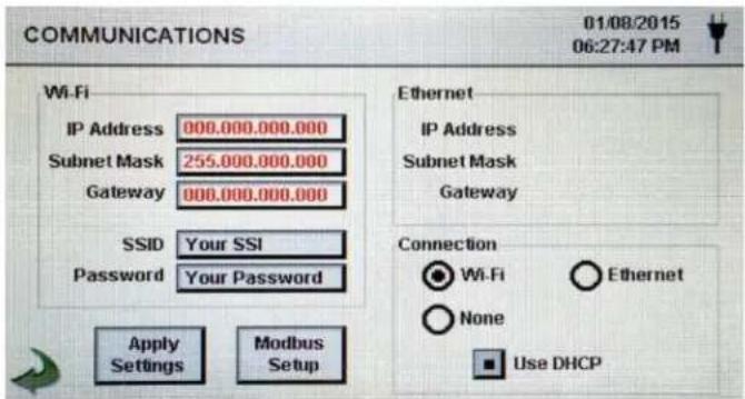
Wi-Fi Communication
The instrument can support an optional Wi-Fi communication module. Select the Wi-Fi radio button for Wi-Fi connection.
text_image
COMMUNICATIONS 01/08/2015 06:27:47 PM Wi-Fi IP Address 000.000.000.000 Subnet Mask 255.000.000.000 Gateway 000.000.000.000 SSID Your SSI Password Your Password Apply Modbus Settings Setup Ethernet IP Address Subnet Mask Gateway Connection ● Wi-Fi ○ Ethernet ○ None ■ Use DHCPUse DHCP
When the DHCP button is selected the instrument will obtain an IP address, subnet mask and gateway information from the router automatically.
Wi-Fi IP Address, Subnet Mask, & Gateway
If the DHCP button is not selected Press the IP Address, Subnet Mask and Gateway windows to enter the desired values for your router. A numeric keypad will be displayed for entering these values. To select the value to change, use the < or > to move cursor. When complete press OK button.
Wi-Fi SSID
Press the Wi-Fi SSID window to enter the Wi-Fi SSID and press OK.
NOTE: Case Sensitive.
Wi-Fi Password
Press the Wi-Fi Password window to enter the Wi-Fi Password and press OK. NOTE: Case Sensitive.
Modbus Setup
Press the Modbus Setup icon to open the Modbus Setup screen.

text_image
MODBUS SETUP 01/09/2015 11:33:23 AM Modbus Address 247 Mode ASCII RTU TCP Baud 9600 19200 38400 57600 115200 Parity None Event Odd Register Set TCP Port 00502 TCP Config Port 05000 Apply SettingsModbus Address
Press the Modbus Address window to open the Enter Modbus Address (0-247) screen. A numeric keypad will be displayed for entering these values. To select the value to change, use the < or > to move cursor. When complete press OK button.
TCP Port
Press the TCP Port window to open the Enter Modbus TCP Port screen. A numeric keypad will be displayed for entering these values. To select the value to change, use the < or > to move cursor. When complete press OK button.
TCP Link Timeout
The TCP Link Timeout is useful when a connection to a remote computer is absent for longer than the expected time (perhaps due to a router connection drop). This could allow the connection to be automatically reestablished.
Press the TCP Link Timeout window to open the Enter Modbus TCP Link Timeout screen. A numeric keypad will be displayed for entering the number of timeout seconds. To select the value to change, use the < or > to move cursor. When complete press OK button.
NOTE: Setting the TCP Link Timeout to 0 disables the timeout function.
Mode
Select ASCII, RTU, or TCP.

| Baud | Select 9600, 19200, 38400, 57,600, or115200. |
| Parity | Select Parity, Odd, Even, or None. |
| Register Set | Select Register Set. |
| RS-232 or RS-485 | Select RS-232 or RS-485 radio button.NOTE:The Baud, Parit,y and RS-232 or RS-485 are not used if TCP is selected. |
| Apply Settings | Press the Apply Settings icon to apply Modbus Setup settings. |
| Back Arrow Icon | Press the Back Arrow icon to return to the previous screen. |
| MODBUS Register Map | The MODBUS register map can be found in the Appendix at the back of this manual. |
| Internet of Things (IOT) | The instrument can communicate to remote servers over a network or the Internet. The setup of this JSON protocol for IOT can be found in the IMS Manual. |
6-8 Environment

Press the Environment icon to open the Environment screen to set Barometric Pressure (BP) Units, Temperature (Temp) Units, Enable Low and High Alarm, Setting Low and High Alarm and Show on Home.
Environment Setting Screen
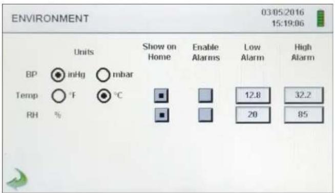
text_image
ENVIRONMENT 03/05/2016 15:19:06 Units BP inHg mbar Temp °F °C RH % Show on Home Enable Alarms Low Alarm High Alarm 12.8 32.2 20 85Units Select Barometric Pressure (BP) Units in Inches of Mercury (inHg) or Millibar (mbar).
Select Temperature (Temp) Units in Fahrenheit (°F) or Celsius (°C).
Show on Home Select Show on Home Button to display the selected value on the Main screen.
Enable Alarms Select the Enable Alarm button to Enable Alarms.
Low Alarm Press the Low Alarm window to open the Enter Low Threshold screen. A numeric keypad will be displayed for entering these values. To select the value to change, use the < or > to move cursor. When complete press OK button.
High Alarm Press the High Alarm window to open the Enter High Threshold screen. A numeric keypad will be displayed for entering these values. To select the value to change, use the < or > to move cursor. When complete press OK button.
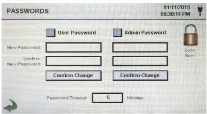
6-9 Passwords

Press the Password Setup icon to open the Passwords screen.
Password Setup Screen
text_image
01/11/2015 06:30:14 PM User Password Admin Password New Password: Confirm New Password: Confirm Change Confirm Change Password Timeout: 5 Minutes Lock Now| User Password | Select the User Password button to enable User Password, preventing any unauthorized use of the instrument. The User Password allows the use of the instrument in its current configuration and saving samples. |
| New Password Confirm New Password | Press the New Password window to open the Enter New User Password (4-15 Chars) screen. Press the Confirm New Password window to open the Confirm New User Password (4-15 Chars) screen. Press Confirm Change Button to save changes.NOTE: The default User Password is 1234. |
| Admin Password | Select the Admin Password button to enable Admin Password, preventing access to Settings screens, Time/Date, and configurations by Users. |
| New Password Confirm New Password | Press the New Password window to open the Enter New Admin Password (4-15 Chars) screen. Press the Confirm Admin Password window to open the Confirm New Admin Password (4-15 Chars) screen.NOTE: The default Admin Password is 4321. |
| Password Timeout | Press the Password Timeout window to enter the number of minutes (1-99) the instrument will timeout due to inactivity. A numeric keypad will be displayed for entering these values. To select the value to change, use the < or > to move cursor. When complete press OK button.NOTE: The default is five (5) minutes. |
| Lock Now | Press the Lock Now icon to immediately lock the instrument.LOST PASSWORD: Please call or email PCE Instruments for a temporary password that will be valid for the day the password is requested.NOTE: This unique password will automatically expire at the end of the day it is issued. |
6-10 Screens

Press the Screens icon to open the Config. Screens window. Select Particles, Real-time meter, Graph, and/or PM Environmental to activate the screens shown when repeatedly pressing the Screens icon on the Main page.
7-1 Power Management

Press the AC Adapter icon or Battery Indicator icon to open the Power Management screen.
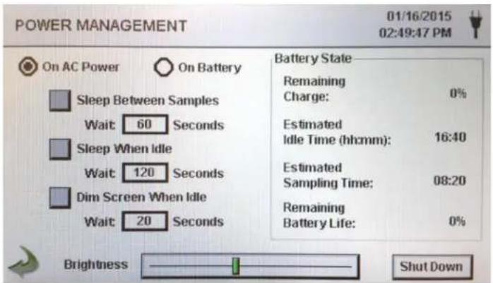
text_image
POWER MANAGEMENT 01/16/2015 02:49:47 PM On AC Power On Battery Sleep Between Samples Wait 60 Seconds Sleep When Idle Wait 120 Seconds Dim Screen When Idle Wait 20 Seconds Battery State Remaining Charge: 0% Estimated Idle Time (hh:mm): 16:40 Estimated Sampling Time: 08:20 Remaining Battery Life: 0% Brightness Shut Down
AC Adapter Icon
The AC Adapter icon is visible when the instrument is plugged into AC mains power.

Battery Indicator Icon
The Battery Indicator icon is visible when the instruments is operating with battery power. The icon also serves as a visual indication of the battery's power level. The battery power level icon will display differently depending on the amount of battery power remaining. The power level indications are as follows:

bar
| Category | Value (%) | |---|---| | Green Bar | 100 | | Yellow Bar | 80 | | Black Bar | 60 | | Yellow Bar | 40 | | Red Bar | 20 |Battery State Remaining Charge
Percent of battery charge remaining.
Battery State Estimated Idle Time
Estimated amount of time remaining if the instrument is powered on without sampling.
Battery State Estimated Sampling Time
Estimated amount of time remaining if the instrument is sampling.
Battery State Remaining Battery Life
Percent of battery life remaining.
On AC Power On Battery
Select the radio button to choose the settings for On AC Power and ON Battery.
| Sleep Between Samples | Selecting the Sleep Between Samples button activates the feature for powering down the instrument between samples to conserve battery life. Press the Sleep Between Samples Wait window to open the Enter Wait Time screen. A numeric keypad will be displayed for entering the Wait Time in seconds from 0 to 65,535. To select the value to change, use the < or > to move cursor. When complete press OK button.NOTE: A Hold Time has to be set for a minimum of 38 seconds in order to activate Sleep Between Samples. |
| Sleep When Idle | Selecting the Sleep When Idle button activates the feature for powering down the instrument when idle. Press the Sleep When Idle Wait window to open the Enter Wait Time screen. A numeric keypad will be displayed for entering the Wait Time in seconds from 10 to 65,535. To select the value to change, use the < or > to move cursor. When complete press OK button. |
| Dim Screen When Idle | Selecting the Dim Screen When Idle button activates the feature for dimming the instrument's screen when idle. Press the Dim Screen When Idle Wait window to open the Enter Wait Time screen. A numeric keypad will be displayed for entering the Wait Time in seconds. To select the value to change, use the < or > to move cursor. When complete press OK button.NOTE: The minimum Dim Screen When Idle Wait Time is 10 seconds. |
| Brightness Slider | Press and slide the Brightness Slider to increase and decrease screen brightness. |
| Shut Down Icon | Press the Shutdown Icon to immediately Shut Down the instrument. |
| Back Arrow Icon | Press the Back Arrow icon to return to the previous screen. |

8-1 Volume Controls

Volume Control Icon
Press the Volume Control icon to enable the Volume Control Slider. Slide the Volume Control Slider Bar to adjust the volume. A numeric value appears at the bottom of the slider to indicate relative volume. Moving the Volume Control Slider Bar to 0 mutes the instrument.
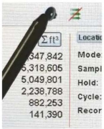
text_image
Σft³ 347,842 5,318,605 5,049,801 2,238,788 882,253 141,390 Location Mode: Sampl Hold: Cycle: Recor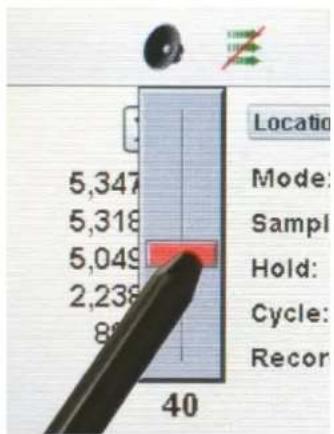
text_image
5,347 5,318 5,049 2,238 8 40 Location Mode: Sample Hold: Cycle: Record9-1 Instrument Management Software (IMS)
The instrument includes a PC based software utility for real-time graphing, downloading data from the instrument, field calibration of sensors, firmware updates, remote diagnostics direct to a service technician, and more.
NOTE: Detailed instructions for the use of the IMS software are contained in the IMS Software Manual on the included USB thumb drive.
Software Installation
Plug the provided thumb drive into your Windows PC and select the IMS Install web installer application file. Follow the installation prompts.

Start Software
Use the IMS Icon in the program folder or on the desktop to start the program.
No Connection
USB Connection
Connection Indication
Connect the instrument to a PC with the provided USB cable to establish a connection between IMS and the instrument. When a connection has been established the Green USB Connection indication will appear.
10-1 Remote Operation
The instrument may be accessed with a web browser via Ethernet (wired or Wi-Fi), using the instruments IP address found in the Communications screen. The following functions can be performed remotely: Start and Stop sampling, change Data Units, select Locations and turn on/off displayed channel values.
The Instrument must be placed in Ethernet or optional Wi-Fi mode and the unit must also be connected to a working router on the same network as the PC.
In the Communications screen, select the Use DHCP button and the unit will automatically display the router issued settings. Enter the displayed IP address into any device browser to access the remote screen.
NOTE: The URL address is the IP address that the DHCP Router assigned to the instrument. A static IP address can be provided for the device through the Communications screen by deselecting the Use DHCP button and entering the IP address.
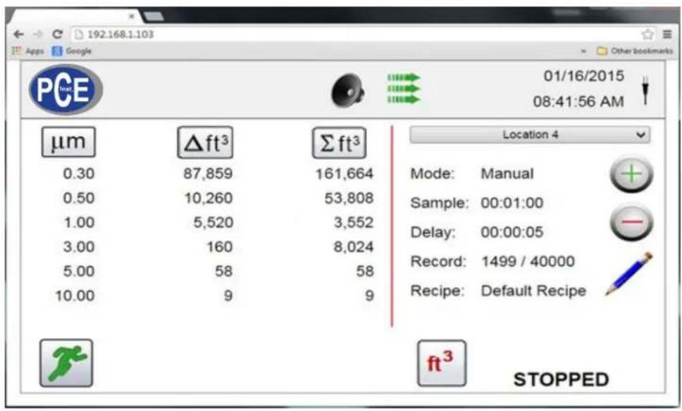
text_image
192:168.1.103 Apps Google Other bookmarks PCE 01/16/2015 08:41:56 AM μm Δft³ Σft³ 0.30 87,859 161,664 0.50 10,260 53,808 1.00 5,520 3,552 3.00 160 8,024 5.00 58 58 10.00 9 9 Location 4 Mode: Manual Sample: 00:01:00 Delay: 00:00:05 Record: 1499 / 40000 Recipe: Default Recipe ft³ STOPPEDAppendix – A
Modbus Register Map
The MODBUS Register Map can be found on the USB thumb drive.
Appendix - B
Environmental Sensor Data Logging
Environmental sensor data can be logged without running the pump or laser by deselecting all particle channels on the Channel Management screen. An All Channels Are Disabled screen will appear when the Back Arrow button is pressed. Press Yes to confirm and No to cancel.
PCE Inst.
59872 Meschede, Germany
Germany: +49 2903 976990
USA: +1 (561) 320-9162
www.pce-instruments.com