USB7016 - Unspecified Microchip - Free user manual and instructions
Find the device manual for free USB7016 Microchip in PDF.

User questions about USB7016 Microchip
0 question about this device. Answer the ones you know or ask your own.
Ask a new question about this device
Download the instructions for your Unspecified in PDF format for free! Find your manual USB7016 - Microchip and take your electronic device back in hand. On this page are published all the documents necessary for the use of your device. USB7016 by Microchip.
USER MANUAL USB7016 Microchip
Note the following details of the code protection feature on Microchip products:
- Microchip products meet the specifications contained in their particular Microchip Data Sheet.
- Microchip believes that its family of products is secure when used in the intended manner, within operating specifications, and under normal conditions.
- Microchip values and aggressively protects its intellectual property rights. Attempts to breach the code protection features of Microchip product is strictly prohibited and may violate the Digital Millennium Copyright Act.
- Neither Microchip nor any other semiconductor manufacturer can guarantee the security of its code. Code protection does not mean that we are guaranteeing the product is "unbreakable" Code protection is constantly evolving. Microchip is committed to continuously improving the code protection features of our products.
This publication and the information herein may be used only with Microchip products, including to design, test, and integrate Microchip products with your application. Use of this information in any other manner violates these terms. Information regarding device applications is provided only for your convenience and may be superseded by updates. It is your responsibility to ensure that your application meets with your specifications. Contact your local Microchip sales office for additional support or, obtain additional support at https://www.microchip.com/en-us/support/design-help/client-support-services.
THIS INFORMATION IS PROVIDED BY MICROCHIP "AS IS". MICROCHIP MAKES NO REPRESENTATIONS OR WARRANTIES OF ANY KIND WHETHER EXPRESS OR IMPLIED, WRITTEN OR ORAL, STATUTORY OR OTHERWISE, RELATED TO THE INFORMATION INCLUDING BUT NOT LIMITED TO ANY IMPLIED WARRANTIES OF NON- INFRINGEMENT, MERCHANTABILITY, AND FITNESS FOR A PARTICULAR PURPOSE, OR WARRANTIES RELATED TO ITS CONDITION, QUALITY, OR PERFORMANCE.
IN NO EVENT WILL MICROCHIP BE LIABLE FOR ANY INDI-RECT, SPECIAL, PUNITIVE, INCIDENTAL, OR CONSEQUENTIAL LOSS, DAMAGE, COST, OR EXPENSE OF ANY KIND WHATSOEVER RELATED TO THE INFORMATION OR ITS USE, HOWEVER CAUSED, EVEN IF MICROCHIP HAS BEEN ADVISED OF THE POSSIBILITY OR THE DAMAGES ARE FORESEEABLE. TO THE FULLEST EXTENT ALLOWED BY LAW, MICROCHIP'S TOTAL LIABILITY ON ALL CLAIMS IN ANY WAY RELATED TO THE INFORMATION OR ITS USE WILL NOT EXCEED THE AMOUNT OF FEES, IF ANY, THAT YOU HAVE PAID DIRECTLY TO MICROCHIP FOR THE INFORMATION.
Use of Microchip devices in life support and/or safety applications is entirely at the buyer's risk, and the buyer agrees to defend, indemnify and hold harmless Microchip from any and all damages, claims, suits, or expenses resulting from such use. No licenses are conveyed, implicitly or otherwise, under any Microchip intellectual property rights unless otherwise stated.
Trademarks
The Microchip name and logo, the Microchip logo, Adaptec, AVR, AVR logo, AVR Freaks, BesTime, BitCloud, CryptoMemory, CryptoRF, dsPIC, flexPWR, HELDO, IGLOO, JukeBlox, KeeLoq, Kleer, LANCheck, LinkMD, maXStylus, maXTouch, MediaLB, megaAVR, Microsemi, Microsemi logo, MOST, MOST logo, MPLAB, OptoLyzer, PIC, picoPower, PICSTART, PIC32 logo, PolarFire, Prochip Designer, QTouch, SAM-BA, SenGenuity, SpyNIC, SST, SST Logo, SuperFlash, Symmetricom, SyncServer, Tachyon, TimeSource, tinyAVR, UNI/O, Vectron, and XMEGA are registered trademarks of Microchip Technology Incorporated in the U.S.A. and other countries.
AgileSwitch, APT, ClockWorks, The Embedded Control Solutions Company, EtherSynch, Flashtec, Hyper Speed Control, HyperLight Load, Libero, motorBench, mTouch, Powermite 3, Precision Edge, ProASIC, ProASIC Plus, ProASIC Plus logo, Quiet-Wire, SmartFusion, SyncWorld, Temux, TimeCesium, TimeHub, TimePictra, TimeProvider, TrueTime, and ZL are registered trademarks of Microchip Technology Incorporated in the U.S.A.
Adjacent Key Suppression, AKS, Analog-for-the-Digital Age, Any Capacitor, AnyIn, AnyOut, Augmented Switching, BlueSky, BodyCom, Clockstudio, CodeGuard, CryptoAuthentication, CryptoAutomotive, CryptoCompanion, CryptoController, dsPICDEM, dsPICDEM.net, Dynamic Average Matching, DAM, ECAN, Espresso T1S, EtherGREEN, GridTime, IdealBridge, In-Circuit Serial Programming, ICSP, INICnet, Intelligent Paralleling, IntelliMOS, Inter-Chip Connectivity, JitterBlocker, Knob-on-Display, KoD, maxCrypto, maxView, memBrain, Mindi, MiWi, MPASM, MPF, MPLAB Certified logo, MPLIB, MPLINK, MultiTRAK, NetDetach, Omniscient Code Generation, PICDEM, PICDEM.net, PICkit, PICtail, PowerSmart, PureSilicon, QMatrix, REAL ICE, Ripple Blocker, RTAX, RTG4, SAM-ICE, Serial Quad I/O, simpleMAP, SimpliPHY, SmartBuffer, SmartHLS, SMART-I.S., storClad, SQI, SuperSwitcher, SuperSwitcher II, Switchtec, SynchroPHY, Total Endurance, Trusted Time, TSHARC, USBCheck, VariSense, VectorBlox, VeriPHY, ViewSpan, WiperLock, XpressConnect, and ZENA are trademarks of Microchip Technology Incorporated in the U.S.A. and other countries.
SQTP is a service mark of Microchip Technology Incorporated in the U.S.A.
The Adaptec logo, Frequency on Demand, Silicon Storage Technology, and Symmcom are registered trademarks of Microchip Technology Inc. in other countries.
GestIC is a registered trademark of Microchip Technology Germany II GmbH & Co. KG, a subsidiary of Microchip Technology Inc., in other countries.
All other trademarks mentioned herein are property of their respective companies.
© 2022, Microchip Technology Incorporated and its subsidiaries.
All Rights Reserved.
ISBN: 978-1-6683-0886-8
For information regarding Microchip's Quality Management Systems, please visit www.microchip.com/quality.
Table of Contents
Preface 5
Introduction....5
Document Layout 5
Conventions Used in this Guide 6
Warranty Registration....7
The Microchip Web Site 7
Development Systems Customer Change Notification Service 7
Customer Support 8
Document Revision History 8
Chapter 1. Overview
1.1 Introduction ...... 9
1.2 Features 9
1.3 Block Diagram 10
1.4 References 11
1.5 Acronyms and Definitions ...... 11
Chapter 2. Getting Started
2.1 Introduction ...... 13
2.2 Kit Contents ...... 13
2.3 Quick Start 13
Chapter 3. Hardware Configuration
3.1 Hardware Configuration Options 15
3.1.1 Configuration 15
3.1.2 Power Source – Self Powered 16
3.1.3 Downstream Port Power Control 17
3.1.4 LED Indicators 17
3.1.5 Switches 18
3.1.6 Connector Descriptions 18
3.1.7 Test Points 19
Appendix A. Schematics
A.1 Introduction 21
Appendix B. Bill of Materials
B.1 Introduction 27
Appendix C. PCB Silk Screens
C.1 Introduction 33
Worldwide Sales and Service 36
NOTES:
Preface
NOTICE TO CUSTOMERS
All documentation becomes dated, and this manual is no exception. Microchip tools and documentation are constantly evolving to meet customer needs, so some actual dialogs and/or tool descriptions may differ from those in this document. Please refer to our web site (www.microchip.com) to obtain the latest documentation available.
Documents are identified with a "DS" number. This number is located on the bottom of each page, in front of the page number. The numbering convention for the DS number is "DSXXXXXA", where "XXXXX" is the document number and "A" is the revision level of the document.
For the most up-to-date information on development tools, see the MPLAB ^® IDE online help. Select the Help menu, and then Topics to open a list of available online help files.
INTRODUCTION
This chapter contains general information that will be useful to know before using the EVB-USB7016 Evaluation Kit User's Guide. Items discussed in this chapter include:
- Document Layout
- Conventions Used in this Guide
- Warranty Registration
• The Microchip Web Site
• Development Systems Customer Change Notification Service - Customer Support
• Document Revision History
DOCUMENT LAYOUT
This document describes how to use the EVB-USB7016 Evaluation Kit as a demonstration platform optimized for portable applications. The manual layout is as follows:
- Chapter 1. "Overview" – This chapter shows a brief description of the EVB-USB7016 Evaluation Kit.
- Chapter 2. “Getting Started” – This chapter provides information about setup and operation of the EVB-USB7016 Evaluation Kit.
- Chapter 3. “Hardware Configuration” – This chapter includes information about the hardware configuration of the EVB-USB7016 Evaluation Kit.
- Appendix A. "Schematics" – This appendix shows the EVB-USB7016 Evaluation Kit schematics.
- Appendix B. "Bill of Materials" – This appendix includes the EVB-USB7016 Evaluation Kit Bill of Materials (BOM).
- Appendix C. “PCB Silk Screens” – This appendix includes the EVB-USB7016 Evaluation Kit silk screen.
CONVENTIONS USED IN THIS GUIDE
This manual uses the following documentation conventions:
DOCUMENTATION CONVENTIONS
| Description Represents Examples | ||
| Arial font: | ||
| Italic characters Referenced books | books MPLAB | ^ IDE User's Guide |
| Emphasized text ...is the only compiler... | ||
| Initial caps A window the Output | window | |
| A dialog the Settings dialog | ||
| A menu selection select Enable Programmer | ||
| Quotes A field name in a window or dialog | "Save project before build" | |
| Underlined, italic text with right angle bracket | A menu path File>Save | —— |
| Bold characters A dialog button | Click OK | |
| A tab | Click the Power tab | |
| N'Rnnnn | A number in verilog format, where N is the total number of digits, R is the radix and n is a digit. | 4'b0010, 2'hF1 |
| Text in angle brackets < > | A key on the keyboard | Press,, |
| Courier New font: | ||
| Plain Courier New | Sample source code | #define START |
| Filenames | autoexec.bat | |
| File paths | c:\mcc18\h | |
| Keywords | _asm, _endasm, static | |
| Command-line options | -Opa+, -Opa- | |
| Bit values | 0, 1 | |
| Constants | 0xFF, 'A' | |
| Italic Courier New | A variable argument | file.o, where file can be any valid filename |
| Square brackets [] | Optional arguments | mcc18 [options] file [options] |
| Curly brackets and pipe character: { | } | Choice of mutually exclusive arguments; an OR selection | errorlevel {0|1} |
| Ellipses... | Replaces repeated text | var_name [, var_name...] |
| Represents code supplied by user | void main (void) { ... } | |
WARRANTY REGISTRATION
Please complete the enclosed Warranty Registration Card and mail it promptly. Sending the Warranty Registration Card entitles users to receive new product updates. Interim software releases are available at the Microchip web site.
Microchip provides online support via our web site at www.microchip.com. This web site is used as a means to make files and information easily available to customers. Accessible by using your favorite Internet browser, the web site contains the following information:
- Product Support – Data sheets and errata, application notes and sample programs, design resources, user's guides and hardware support documents, latest software releases and archived software
- General Technical Support – Frequently Asked Questions (FAQs), technical support requests, online discussion groups, Microchip consultant program member listing
- Business of Microchip – Product selector and ordering guides, latest Microchip press releases, listing of seminars and events, listings of Microchip sales offices, distributors and factory representatives
DEVELOPMENT SYSTEMS CUSTOMER CHANGE NOTIFICATION SERVICE
Microchip's customer notification service helps keep customers current on Microchip products. Subscribers will receive e-mail notification whenever there are changes, updates, revisions or errata related to a specified product family or development tool of interest.
To register, access the Microchip web site at www.microchip.com, click on Customer Change Notification and follow the registration instructions.
The Development Systems product group categories are:
- Compilers – The latest information on Microchip C compilers, assemblers, linkers and other language tools. These include all MPLAB ^ C compilers; all MPLAB assemblers (including MPASM ^TM assembler); all MPLAB linkers (including MPLINK ^TM object linker); and all MPLAB librarians (including MPLIB ^TM object librarian).
- Emulators – The latest information on Microchip in-circuit emulators. This includes the MPLAB REAL ICE and MPLAB ICE 2000 in-circuit emulators.
- In-Circuit Debuggers – The latest information on the Microchip in-circuit debuggers. This includes MPLAB ICD 3 in-circuit debuggers and PICkit™ 3 debug express.
- MPLAB IDE – The latest information on Microchip MPLAB IDE, the Windows Integrated Development Environment for development systems tools. This list is focused on the MPLAB IDE, MPLAB IDE Project Manager, MPLAB Editor and MPLAB SIM simulator, as well as general editing and debugging features.
- Programmers – The latest information on Microchip programmers. These include production programmers such as MPLAB REAL ICE in-circuit emulator, MPLAB ICD 3 in-circuit debugger and MPLAB PM3 device programmers. Also included are nonproduction development programmers such as PICSTART® Plus and PICkit 2 and 3.
CUSTOMER SUPPORT
Users of Microchip products can receive assistance through several channels:
• Distributor or Representative
- Local Sales Office
• Field Application Engineer (FAE)
- Technical Support
Customers should contact their distributor, representative or field application engineer (FAE) for support. Local sales offices are also available to help customers. A listing of sales offices and locations is included in the back of this document.
Technical support is available through the web site at:
http://www.microchip.com/support
DOCUMENT REVISION HISTORY
| Revisions Section/Figure/Entry Correction | ||
| DS50003363A(07-14-22) | Initial release | |
Chapter 1. Overview
1.1 INTRODUCTION
The EVB-USB7016 is a demonstration and evaluation platform that provides the necessary requirements and interface options for evaluating the USB7016, which is a 6-port High-Speed (HS) USB smart hub on a 4-layer RoHS-compliant Printed Circuit Board (PCB). This allows the user to gain an understanding of the product and accelerate the integration of the USB7016 into the user's design.
The EVB-USB7016 is compliant with the USB 2.0 HS, Full-Speed (FS), and Low-Speed (LS) USB signaling. The EVB-USB7016 is also compliant with USB 3 Gen1 on the upstream port and on downstream Ports 1 to 5.
The evaluation platform supports a Type-C Gen1 upstream port and six downstream ports: one USB 3 Gen1 Type-C port, three USB3 Gen1 Type-A ports, and two USB2.0 ports with Type-A connectors. The EVB-USB7016 platform also supports battery charging on all four downstream ports (maximum of 10A[Note 1] at any one time). The EVB-USB7016 supports FlexConnect role reversal for any of the four downstream ports with the upstream port.
The EVB-USB7016 has four configurations for operation through internal default settings and supports custom configurations through SMBus or through the external 16-Mbit SPI Flash device.
The EVB-USB7016 demonstrates driver compatibility with Microsoft ^® Windows ^® 10, Windows 8.x, Windows 7, Windows XP, Mac OS ^® X 10.4+, and Linux ^® hub drivers.
For more information about EVB-USB7016, see Section 1.2 "Features".
Note 1: Requires a 12V, 85W supply.
1.2 FEATURES
- Microchip's PortSwap, PHYBoost ^TM , and VariSense ^TM technologies
- USB7016 in a 100-pin QFN RoHS compliant package
- USB 3 compliant (Gen1 operation)
- USB 2 compliant (HS, FS, and LS operation)
- 5V-tolerant USB pins
• Self-powered operation - USB Gen1 Type-C upstream port
-
Six Downstream USB ports:
-
One Type-C Gen1 downstream port
- Three Type-A Gen1 downstream ports
-
Two Type-A USB 2.0-only downstream ports
-
All downstream ports support individual port power and overcurrent sense.
- All downstream ports can be enabled for battery charging with the battery charging select shunts J1 and J20. (BC1.2 or SE1, 2.1A maximum per port)
- Onboard SPI Flash for external downloadable firmware
-
Operates from a single voltage (+12.0V, regulated) external power supply
-
Onboard 25 MHz crystal or oscillator input
- Single onboard +5.2V, 15A regulator
• Single onboard +3.3V, 0.5A regulator
• Single onboard +1.2V, 2A regulator - Port Power LED indicators
• SPI Flash activity blue LED indicator - Reset red LED indicator
- Green LED indicators for 5V, 3.3V, and 1.2V regulator outputs
- Terminal block connector for use with an external 12 VDC bench supply
- Barrel connector for use with a Microchip 12V power supply
- Removable or non-removable downstream port options can be configured with select shunt on J17.
- Bridge peripheral functions:
- USB-to-UART (CDC)
- USB-to-I ^2 S Audio Codec
- USB-to-SMBus
- USB-to-I ^2 C
1.3 BLOCK DIAGRAM
Figure 1-1 shows the block diagram of EVB-USB7016.
FIGURE 1-1: EVB-USB7016 BLOCK DIAGRAM

flowchart
graph TD
    A["USB7016"] --> B["Hub Controller Logic"]
    B --> C["GPIO 'B'"]
    B --> D["PHY0 PHY0"]
    B --> E["PHY2 PHY2"]
    B --> F["PHY3 PHY3"]
    B --> G["PHY4 PHY4"]
    B --> H["PHY5 PHY5"]
    B --> I["PHY6 PHY6"]
    B --> J["PHY7 PHY7"]
    B --> K["PHY8 PHY8"]
    B --> L["CPU SPI"]
    B --> M["USB3 USB2"]
    B --> N["NFC PHYN"]
    B --> O["Hub Feature Controller"]
    O --> P["OTP"]
    P --> Q["GPIO SMB SPI I²S"]
    P --> R["GPIO SMB SPI I²S"]
    P --> S["GPIO SMB SPI I²S"]
    P --> T["GPIO SMB SPI I²S"]
    P --> U["GPIO SMB SPI I²S"]
    P --> V["GPIO SMB SPI I²S"]
    P --> W["GPIO SMB SPI I²S"]
    P --> X["GPIO SMB SPI I²S"]
    P --> Y["GPIO SMB SPI I²S"]
    P --> Z["GPIO SMB SPI I²S"]
    P --> AA["GPIO SMB SPI I²S"]
    P --> AB["GPIO SMB SPI I²S"]
    P --> AC["GPIO SMB SPI I²S"]
    P --> AD["GPIO SMB SPI I²S"]
    P --> AE["GPIO SMB SPI I²S"]
    P --> AF["GPIO SMB SPI I²S"]
    P --> AG["GPIO SMB SPI I²S"]
    P --> AH["GPIO SMB SPI I²S"]
    P --> AI["GPIO SMB SPI I²S"]
    P --> AJ["GPIO SMB SPI I²S"]
    P --> AK["GPIO SMB SPI I²S"]
    P --> AL["GPIO SMB SPI I²S"]
    P --> AM["GPIO SMB SPI I²S"]
    P --> AN["GPIO SMB SPI I²S"]
    P --> AO["GPIO SMB SPI I²S"]
    P --> AP["GPIO SMB SPI I²S"]
    P --> AQ["GPIO SMB SPI I²S"]
    P --> AR["GPIO SMB SPI I²S"]
    P --> AS["GPIO SMB SPI I²S"]
    P --> AT["GPIO SMB SPI I²S"]
    P --> AU["GPIO SMB SPI I²S"]
    P --> AV["GPIO SMB SPI I²S"]
    P --> AW["GPIO SMB SPI I²S"]
    P --> AX["GPIO SMB SPI I²S"]
    P --> AY["GPIO SMB SPI I²S"]
    P --> AZ["GPIO SMB SPI I²S"]
    P --> BA["GPIO SMB SPI I²S"]
    P --> BB["GPIO SMB SPI I²S"]
    P --> BC["GPIO SMB SPI I²S"]
    P --> BD["GPIO SMB SPI I²S"]
    P --> BE["GPIO SMB SPI I²S"]
    P --> BF["GPIO SMB SPI I²S"]
    P --> BG["GPIO SMB SPI I²S"]
    P --> BH["GPIO SMB SPI I²S"]
    P --> BI["GPIO SMB SPI I²S"]
    P --> BJ["GPIO SMB SPI I²S"]
    P --> BK["GPIO SMB SPI I²S"]
    P --> BL["GPIO SMB SPI I²S"]
    P --> BM["GPIO SMB SPI I²S"]
    P --> BN["GPIO SMB SPI I²S"]
    P --> BO["GPIO SMB SPI I²S"]
    P --> BP["GPIO SMB SPI I²S"]
    P --> BQ["GPIO SMB SPI I²S"]
    P --> BR["GPIO SMB SPI I²S"]
    P --> BS["GPIO SMB SPI I²S"]
    P --> BT["GPIO SMB SPI I²S"]
    P --> BU["GPIO SMB SPI I²S"]
    P --> BV["GPIO SMB SPI I²S"]
    P --> BW["GPIO SMB SPI I²S"]
    P --> BX["GPIO SMB SPI I²S"]
    P --> BY["GPIO SMB SPI I²S"]
    P --> BZ["GPIO SMB SPI I²S"]
    P --> CA["GPIO SMB SPI I²S"]
    P --> CB["GPIO SMB SPI I²S"]
    P --> CC["GPIO SMB SPI I²S"]
    P --> CD["GPIO SMB SPI I²S"]
    P --> CE["GPIO SMB SPI I²S"]
    P --> CF["GPIO SMB SPI I²S"]
    P --> CG["GPIO SMB SPI I²S"]
    P --> CH["GPIO SMB SPI I²S"]
    P --> CI["GPIO SMB SPI I²S"]
    P --> CJ["GPIO SMB SPI I²S"]
    P --> CK["GPIO SMB SPI I²S"]
    P --> CL["GPIO SMB SPI I²S"]
    P --> CD
1.4 REFERENCES
Concepts and materials available in the following documents may be helpful when reading this document. Visit www.microchip.com for the latest documentation.
• USB7016 6-Port USB 3.2 Gen 1 SmartHub Controller Data Sheet
1.5 ACRONYMS AND DEFINITIONS
TABLE 1-1: ACRONYMS AND DEFINITIONS
| Acronym Definition | |
| BC1.2 The latest USB-IF specified USB battery charging standard | |
| CDP Charging Downstream Port, a BC1.2-compliant port allows simultaneous USB data and USB charging | |
| DCP Dedicated Charging Port, a BC1.2-compliant port which is only capable of USB charging (no data) | |
| DFP Downstream Facing Port | |
| EVB Evaluation Board | |
| OTP One-Time-Programmable Memory | |
| SDP | Standard Downstream Port, a standard USB port with no high-current battery charging capabilities |
| SE1 Type of Battery Charging (non-USB compliant) that sets the USB D+/D– to specific DC voltages to communicate charging capability | |
| Type-C Reversible USB Connector | |
| USB-IF USB | Integrators Forum, a collection of corporate sponsored members responsible for developing USB specifications |
| Gen1 USB | Specification 3.2 Gen1 |
NOTES:
Chapter 2. Getting Started
2.1 INTRODUCTION
The Microchip EVB-USB7016 is designed for flexible configuration solutions. It can be configured via default internal register settings, via a downloadable external firmware to an onboard SPI Flash (OTP memory), via SMBus, or via the onboard configuration switches. When configured with the default internal register settings, the device operates as a USB 3.2 Gen1 hub with one upstream Type-C port, one downstream Type-C port, three downstream USB 3 Type-A ports, and two downstream USB 2.0 ports, with Microchip's standard VID/PID/DID settings.
Microchip provides a comprehensive software programming tool, MPLAB ^® Connect (MPLABC), for configuring USB7016 functions, registers, and OTP memory. USB7016 requires MPLABC version 2.1.0 or greater.
For additional information on the MPLABCC programming tool, refer to Software Libraries within the Microchip USB7016 product page at www.microchip.com/USB7016.
2.2 KIT CONTENTS
The EVB-USB7016 Evaluation Kit includes the basic equipment necessary for evaluation. The items included in the kit are:
• EVB-USB7016 Evaluation Board
• Type-A to Type-C USB cable
2.3 QUICK START
To quickly start using the board, perform the following steps:
- Connect a 12V power supply to the barrel connector (J5) or the terminal block (J4) on the EVB-USB7016.
- Using a Type-A to Type-C USB cable, connect the EVB-USB7016 to a USB host via the upstream "Port 0" USB Type-C socket (J1).
Devices may now be connected to any of the downstream ports to enumerate and use those devices with the USB host.
To perform additional configuration or evaluate specific features, launch the MPLABC software on your USB host or manipulate the included hardware configuration options detailed in the next sections.
NOTES:
Chapter 3. Hardware Configuration
3.1 HARDWARE CONFIGURATION OPTIONS
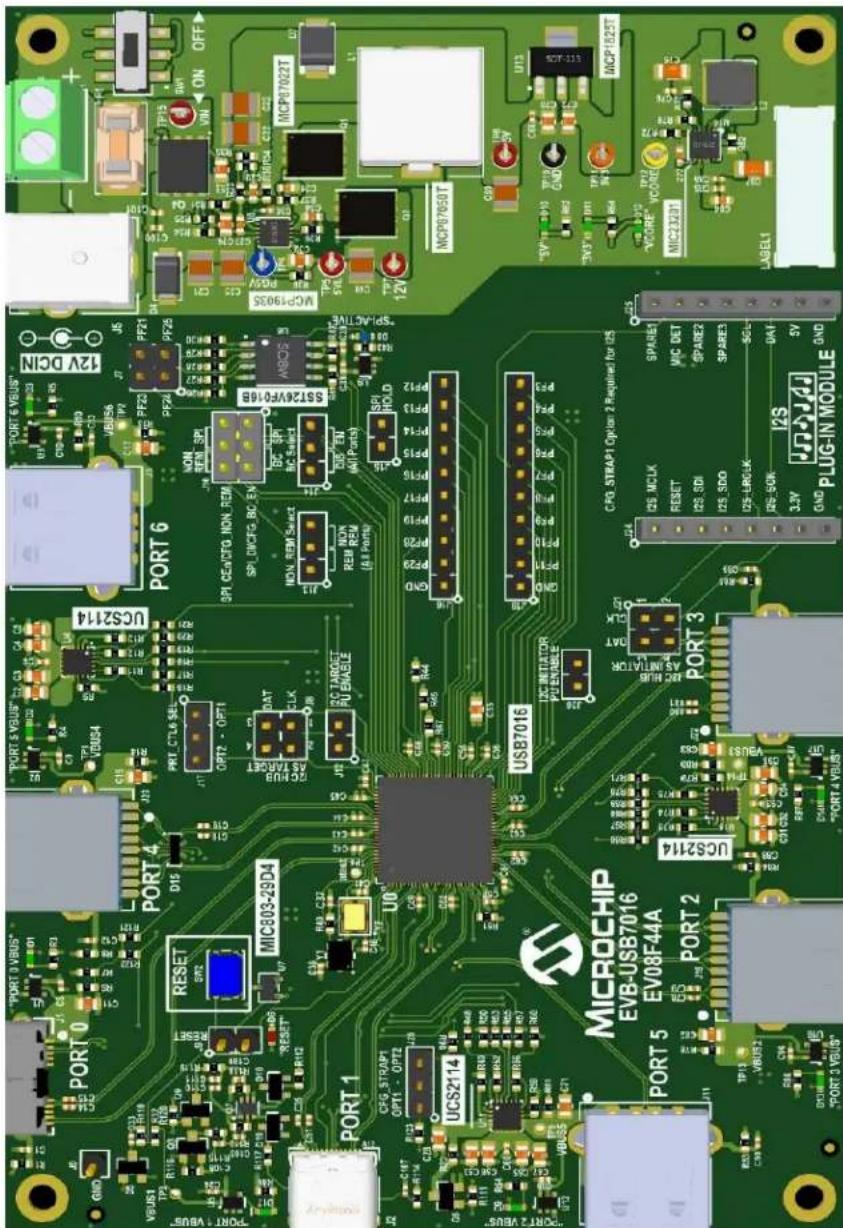
Figure 3-1 shows the top view of the EVB-USB7016.
FIGURE 3-1: EVB-USB7016 (TOP VIEW)
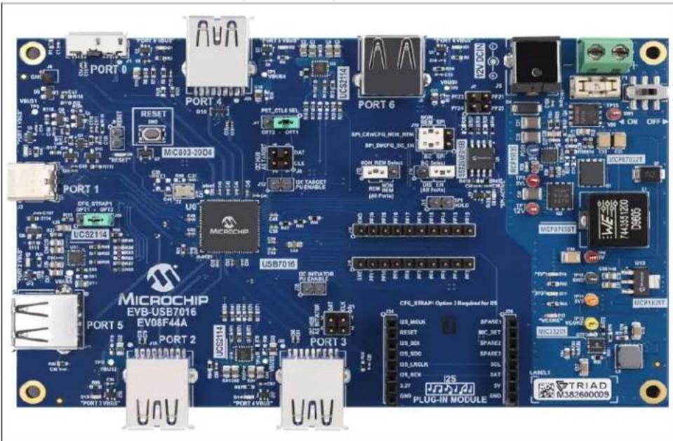
text_image
PORT 0 PORT 4 PORT 6 PORT 1 PORT 3 PORT 5 MICROCHIP EV8-USB7016 EV08F44A PORT 2 U0 MicroCHIP USB7016 CFC_ERAP: Options 1 Required for OS USB_MCLK RESET USB_DCK USB_LCLK USB_BCK USB_CACK USB_CSER USB_CSER USB_CSER USB_CSER USB_CSER USB_CSER USB_CSER USB_CSER USB_CSER USB_CSER USB_CSER USB_CSER USB_CSER USB_CSER USB_CSER USB_CSER USB_CSER USB_CSER USB_CSER USB_CSER USB_CSER USB_CSER USB_CSER USB_CSER USB_CSER USB_CER USB_CER USB_CER USB_CER USB_CER USB_CER USB_CER USB_CER USB_CER USB_CER USB_CER USB_CER USB_CER USB_CER USB_CER USB_CER USB_CER USB_CER USB_CER USB_CER USB_CER USB_CER USB_CER USB_CER USB_CER USB_CES USB_CES USB_CES USB_CES USB_CES USB_CES USB_CES USB_CES USB_CES USB_CES USB_CES USB_CES USB_CES USB_CES USB_CES USB_CES USB_CES USB_CES USB_CES USB_CES USB_CES USB_CES USB_CES USB_CES USB_CES USB_CET100000000000000000000000000000000000000000000000000000000000000000000000000000000000000000000000000003.1.1 Configuration
3.1.1.1 EXTERNAL SPI FLASH
Upon power-up, the USB7016 first looks for an external SPI ROM device and a valid signature in the Flash. If one is found, the external ROM is enabled and code execution is initiated from the external SPI ROM device.
To enable operation from the SPI device, install shunts to pins 1-2 and 4-5 of J10. When the code is executing from an SPI ROM device, a blue LED "SPI-ACTIVE" (D8) illuminates.
Note 1: CFG_BC and CFG_Non-Rem options are deselected when SPI shunts are installed on J10. When operating in SPI mode, all configuration is handled by the code executing from the SPI ROM device.
2: If the SPI Flash is not properly programmed or has an invalid signature, the USB7016 reverts to internal defaults even if the SPI ROM is selected
3.1.1.2 SMBUS
If an SPI Flash device is not found, the firmware checks if SMBus is enabled.
To select SMBus configuration, leave J10 open to disconnect the SPI ROM. To connect the SMBus pull-up resistors, connect a shunt to J12 pins 1 and 2. The SMBus signals may be accessed at J8, where pin 1 is the clock and pin 3 is data (pin 2 is ground).
If configuration SMBus is enabled (i.e. SMBus clock and data are pulled up), the USB7016 waits indefinitely for data from the SMBus interface and will not enumerate to the USB host until the special USB Attach command is sent.
3.1.1.3 INTERNAL DEFAULT CONFIGURATIONS WITH STRAPPING OPTIONS
When the USB7016 does not detect a valid SPI Flash image and does not look for SMBus configuration upon power-up, the USB7016 uses internal default register settings. It also sets the Vendor ID, Product ID, Language ID, and Device ID, and additional settings from the internal ROM code.
If configuration is not done through SPI or SMBus, additional configuration is available through two functions: CFG_BC_EN and CFG_NON-REM. The controls are configured by selecting one of the six resistor values for each pin. The EVB-USB7016 demonstrates two of the six possible resistor values for each of CFG_BC_EN and CFG_NON-REM. These straps are sensed by the USB7016 device at power-on to determine the resultant configuration of the device.
To select the CFG_BC_EN and CFG_NON-REM modes, shunts must be connected to J10, J13, and J14 headers.
To use the battery charging strap options, connect a shunt to pins 2 and 3 of J10 and connect a shunt to J14 according to Table 3-1. For the NON_REM strap options, connect a shunt to pins 5 and 6 of J10 and connect a shunt to J13 according to Table 3-2.
TABLE 3-1: BATTERY CHARGING OPTIONS (CFG_BC_EN - J14)
| J14 Shunt Position (J10 is shunted pins 2-3.) |
| 2-3 All ports are BC 1.2-disabled. |
| 1-2 All downstream ports are BC1.2-enabled. |
TABLE 3-2: NON-REMOVABLE PORT OPTIONS (CFG_NON-REM - J13)
| J13 Shunt Position (J10 is shunted pins 5-6.) |
| 1-2 All ports are non-removable. |
| 2-3 All ports are removable. |
3.1.2 Power Source – Self Powered
The EVB-USB7016 only supports self-powered operation. Power is supplied through one +12.0V regulated external power supply. The power supply is connected to the 2.5 mm connector J5 on the board. Alternatively, an external voltage can be supplied to the screw terminal "12V" (J4). The +12.0V feeds a 15A regulator that outputs +5.2V (nominal) across the board and also supplies the +3.3V regulator and the 1.2V regulator.
CAUTION
The supplied 12.0V external power supply cannot support simultaneous battery charging on all downstream ports. Use a higher power supply if the required test use case exceeds the power capability of the supply. Failure to heed to this warning could result in damage to the 12.0V external power supply.
3.1.3 Downstream Port Power Control
USB power to the six downstream ports is controlled via port power controllers with auto-discharge functionality. All downstream ports support BC 1.2 battery charging.
The five downstream USB 3 ports and additional USB 2 port are each capable of up to 3A of current at 5V.
3.1.4 LED Indicators
Table 3-3 describes the LED indicators on the EVB-USB7016.
TABLE 3-3: EVB-USB7016 LED INDICATOR DESCRIPTIONS
| Ref.Des. | Label Description |
| D8 “SPI-ACTIVE” Indicates | SPI Flash Memory activity |
| D6 | “RESET” The RST_N signal is asserted. |
| D1 “Upstream VBUS” | Illuminates when 5V to upstream PORT0 VBUS is present |
| D17 “PORT 1 VBUS” Illuminates when 5V to upstream PORT1 VBUS is present | |
| D13 “PORT 2 VBUS” Illuminates when 5V to upstream PORT2 VBUS is present | |
| D14 “PORT 3 VBUS” Illuminates when 5V to upstream PORT3 VBUS is present | |
| D2 “PORT 4 VBUS” Illuminates when 5V to upstream PORT4 VBUS is present | |
| D9 “PORT 5 VBUS” Illuminates when 5V to upstream PORT5 VBUS is present | |
| D3 “PORT 6 VBUS” Illuminates when 5V to upstream PORT6 VBUS is present | |
| D10 “5V” Illuminates when 5V is present from the 5V voltage regulator | |
| D11 | “3V3” Illuminates when 3.3V is present from the 3.3V voltage regulator |
| D12 | “VCORE” Illuminates when 1.2V (VCORE) is present from the 1.2V regulator |
3.1.5 Switches
Table 3-4 describes the switches on the EVB-USB7016.
TABLE 3-4: EVB-USB7016 SWITCH DESCRIPTIONS
| Ref. Des. Label Description | |
| SW2 “RESET” Momentary push-button switch to assert RST_N | |
| SW1 “ON/OFF” Connects or disconnects the 12 VDC supply | |
3.1.6 Connector Descriptions
Table 3-5 describes the connectors included on the PCB.
TABLE 3-5: EVB-USB7016 CONNECTOR DESCRIPTIONS
| Ref. Des. | Type Label Description | ||
| J5 Barrel Jack “12VDC” 12 VDC supply connection (center pin positive) | |||
| J4 | 2-pin terminal block | — | Alternative 12 VDC supply connec-tion. Pin 1 is positive. |
| J1 USB Type-B Connector | “PORT0” | Upstream Type-A connection | |
| J2 USB Type-C Connector | “PORT1” | Downstream Port 1 USB connection | |
| J19 | USB Type-A Connector | “PORT2” | Downstream Port 2 USB connection |
| J22 | USB2 Type-A Connector | “PORT3” | Downstream Port 3 USB connection |
| J23 | USB2 Type-A Connector | “PORT4” | Downstream Port 4 USB connection |
| J11 | USB Type-A Connector | “PORT5” | Downstream Port 5 USB connection |
| J3 USB Type-A Connector | “PORT6” | Downstream Port 6 USB connection | |
| J15 | 1x2 Header | “HOLD” | When shunted, disables the SPI memory |
| J10 | 2x3 Header | “SPI_DI/CFG_BC_EN” “SPI_CEn/CFG_NON_REM” | Selects between SPI memory capabil-ity and BC/NON_REM capability. For SPI, connect pins 2 and 3 as well as 5 and 6. For BC, connect pins 4 and 5. For NON_REM, connect pins 1 and 2. |
| J9 | 2x1 Header | “Ext.Reset” | Connection for an external Reset switch |
| J7 | 2x2 Header | PF24 PF23 PF25 PF21 | SPI data pins provided for debugging SPI memory |
| J6 | 1x1 Header | “GND” | Circuit Ground |
| J18 | 1x10 Header | — | PF3 – PF11 |
| J16 | 1x10 Header | — | PF12 – PF29 |
| J20 | 1x2 Header | “PU” | Pull-up resistors, I^2C Initiator |
| J12 | 1x2 Header | “PU” | Pull-up resistors, I^2C Target |
| J14 | 1x3 Header | “BC SELECT” | See Table 3-1. |
| Ref.Des. | Type | Label | Description |
| J13 1x3 Header “NON_REM_SELECT” See Table 3-2. | |||
| J17 1x3 Header “PRT_CTL6 SEL” Default OPT 1 | |||
| J24 1x8 Header — Audio Codec Socket | |||
| J25 1x8 Header — Audio Codec Socket | |||
3.1.7 Test Points
Table 3-6 describes the test points on the EVB-USB7016. A header may be permanently installed on the through-hole test points if needed.
TABLE 3-6: EVB-USB7016 TEST POINT DESCRIPTIONS
| Ref. Des. Type Description | ||
| TP1 Test Pad | VBUS Port 4 | |
| TP2 Test Pad | VBUS Port 6 | |
| TP3 Test Pad | VBUS Port 1 | |
| TP4 Test Pad | PG5V | |
| TP5 Test Pad | 5VL | |
| TP6 Test Pad | ATEST | |
| TP7 | Test Loop (Red) | 12V |
| TP8 Test Pad | 5V | |
| TP9 Test Pad | VBUS Port 5 | |
| TP10 | Test Loop (Black) Circuit Ground | |
| TP11 | Test Loop (Orange) | 3.3V |
| TP12 | Test Loop (Yellow) | VCORE (1.2V) |
| TP13 | Test Pad | VBUS Port 2 |
| TP14 | Test Pad | VBUS Port 3 |
| TP15 | Test Loop (Red) | VIN |
NOTES:
Appendix A. Schematics
A.1 INTRODUCTION
This appendix shows the EVB-USB7016 Evaluation Kit schematics.
FIGURE A-1: EVB-USB7016 AND UPSTREAM PORT
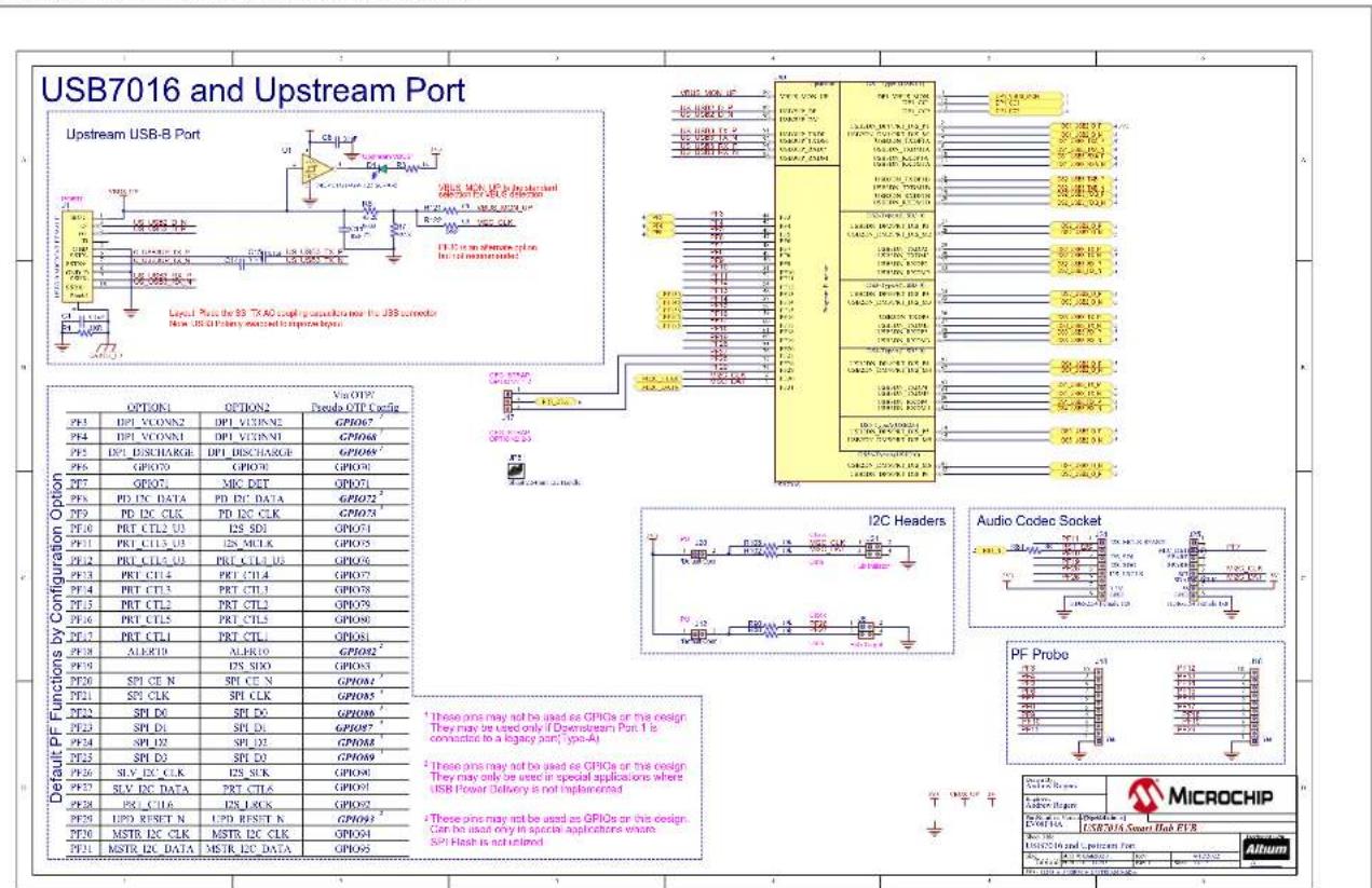
text_image
USB7016 and Upstream Port Upstream USB-B Port Level Plus for 83.74.00 chip configuration for USB connector New USB-DI Primary channel to control ports. OPTION1 OPTION2 Vcc QFP Pseudo OTP Cyclic PF3 DPI VCONN2 DPI VOUTN5 GPI067 PF4 DPI VCONN1 DPI VOUTN1 GPI068 PF5 DPI DISCHARGE DPI DISCHARGE GPI069 PF6 GPI070 GPI071 MRC DET GPI072 PF7 PD DC DATA PD DC DATA GPI073 PF8 PD DC CLK PD DC CLK GPI074 PF9 PRT CTL2 U3 I2S SD1 GPI075 PF10 PRT CTL3 U3 I2S MCLK GPI076 PF11 PRT CTL4 U3 PRT CTL4 U3 GPI077 PF12 PRT CTL4 PRT CTL4 PRTCTL3 GPI078 PF13 PRT CTL5 PRT CTL5 PRTCTL4 GPI079 PF14 PRT CTL1 PRT CTL1 PRTCTL2 GPI080 PF15 ALERID ALERID GPI081 PF16 SP1 CE N SPT CE N GPI082 PF17 SP1 CLK SPT CLK GPI083 PF18 SP1 D0 SPT D0 GPI084 PF19 SP1 D1 SPT D1 GPI085 PF20 SP1 D2 SPT D2 GPI086 PF21 SP1 D3 SPT D3 GPI087 PF22 SLV EX CLK I2S SLK GPI088 PF23 SLV DC DATA PRT CTL6 GPI089 PF24 PSI CL6 I2S LOCK GPI090 PF25 UPD RESET N UPD RESET N GPI091 PF26 MSTR DC CLK MSTR DC CLK GPI092 PF27 MSTR DC DATA MSTR DC DATA GPI093 Default PF Functions by Configuration Option I2C Headers Audio Codec Socket PF Probe MICROCHIP MicrochipFIGURE A-2: EVB-USB7016 DOWNSTREAM PORT 1
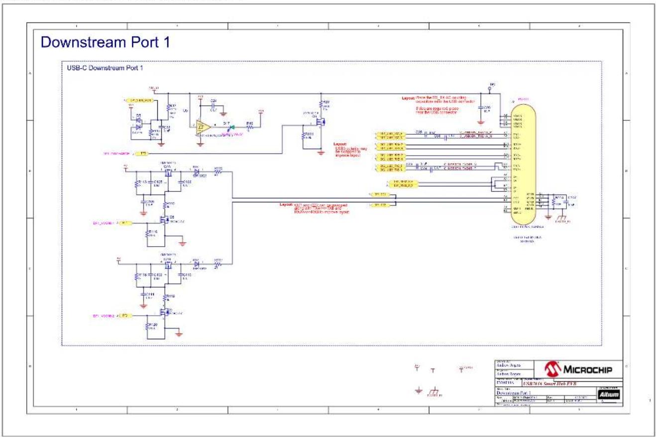
text_image
Downstream Port 1 USB-C Downstream Port 1 Layout: USB_C driving, only be connected to inverse ports Layout: USB_C driving, only be connected to inverse ports Layout: USB_C driving, only be connected to inverse ports Layout: USB_C driving, only be connected to inverse ports MicroCHIP MicroCHIP MicroCHIP MicroCHIP MicroCHIP MicroCHIP MicroCHIP MicroCHIP MicroCHIP MicroCHIP MicroCHIP MicroCHIP MicroCHIP MicroCHIP MicroCHIP MicroCHIP MicroCHIP MicroCHIP MicroCHIP MicroCHIP MicroCHIP MicroCHIP MicroCHIP MicroCHIP MicroCHIP MicroCHIP MicroCHIP MicroCHIP MicroCHIP MicroCHIP MicroCHIP MicroCHIP MicroCHIP MicroCHIPFIGURE A-3: EVB-USB7016 DOWNSTREAM PORTS 2-6
Downstream Ports 2-6
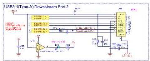
text_image
USB3.1(Type-A) Downstream Port 2 LED LED pinout LED pinout LED pinout LED pinout LED pinout LED pinout LED pinout LED pinout LED pinout LED pinout LED pinout LED pinout LED pinout LED pinout LED pinout LED pinout LED pinout LED pinout LED pinout LED pinout LED pinout LED pinout LED pinout LED pinout LED pinout LED pinOUT LED pinOUT LED pinOUT LED pinOUT LED pinOUT LED pinOUT LED pinOUT LED pinOUT LED pinOUT LED pinOUT LED pinOUT LED pinOUT LED pinOUT LED pinOUT LED pinOUT LED pinOUT LED pinOUT LED pinOUT LED pinOUT LED pinOUT LED pinOUT LED pinOUT LED pinOUT LED pinOUT LED pinOUT LED pinIN LED pinIN LED pinIN LED pinIN LED pinIN LED pinIN LED pinIN LED pinIN LED pinIN LED pinIN LED pinIN LED pinIN LED pinIN LED pinIN LED pinIN LED pinIN LED pinIN LED pinIN LED pinIN LED pinIN LED pinIN LED pinIN LED pinIN LED pinIN LED pinIN LED pinOUT
text_image
USB3.1(Type-A) Downstream Port 5 U12 VCC C29 U13 VCC VCC VCC VCC VCC VCC VCC VCC VCC VCC VCC VCC VCC VCC VCC VCC VCC VCC VCC VCC VCC VCC VCC VCC VCC VCC VCC VCC VCC VCC VCC VCC VCC VCC
text_image
USB3.1(Type-A) Downstream Port 3 LPG LED display ON/OFF Power supply Control Output Pin 1 Pin 2 Pin 3 Pin 4 Pin 5 Pin 6 Pin 7 Pin 8 Pin 9 Pin 10 Pin 11 Pin 12 Pin 13 Pin 14 Pin 15 Pin 16 Pin 17 Pin 18 Pin 19 Pin 20 Pin 21 Pin 22 Pin 23 Pin 24 Pin 25 Pin 26 Pin 27 Pin 28 Pin 29 Pin 30 Pin 31 Pin 32 Pin 33 Pin 34 Pin 35 Pin 36 Pin 37 Pin 38 Pin 39 Pin 40 Pin 41 Pin 42 Pin 43 Pin 44 Pin 45 Pin 46 Pin 47 Pin 48 Pin 49 Pin 50 Pin 51 Pin 52 Pin 53 Pin 54 Pin 55 Pin 56 Pin 57 Pin 58 Pin 59 Pin 60 Pin 61 Pin 62 Pin 63 Pin 64 Pin 65 Pin 66 Pin 67 Pin 68 Pin 69 Pin 70 Pin 71 Pin 72 Pin 73 Pin 74 Pin 75 Pin 76 Pin 77 Pin 78 Pin 79 Pin 80 Pin 81 Pin 82 Pin 83 Pin 84 Pin 85 Pin 86 Pin 87 Pin 88 Pin 89 Pin 90 Pin 91 Pin 92 Pin 93 Pin 94 Pin 95 Pin 96 Pin 97 Pin 98 Pin 99 Pin100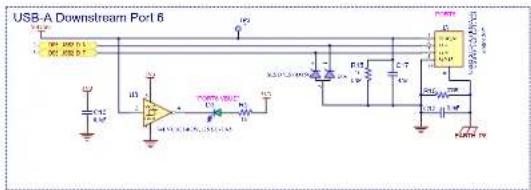
text_image
USB-A Downstream Port 6 USB-A USB-B C12 C13 D1 D2 D3 D4 D5 D6 D7 D8 D9 D10 D11 D12 D13 D14 D15 D16 D17 D18 D19 D20 D21 D22 D23 D24 D25 D26 D27 D28 D29 D30 D31 D32 D33 D34 D35 D36 D37 D38 D39 D40 D41 D42 D43 D44 D45 D46 D47 D48 D49 D50 D51 D52 D53 D54 D55 D56 D57 D58 D59 D60 D61 D62 D63 D64 D65 D66 D67 D68 D69 D70 D71 D72 D73 D74 D75 D76 D77 D78 D79 D80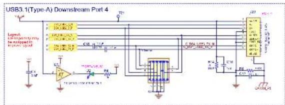
text_image
USB3.1(Type-A) Downstream Port 4 Legend: Lipency to the output in the output C10 C20 C30 C40 C50 C60 C70 C80 C90 C100 C110 C120 C130 C140 C150 C160 C170 C180 C190 C200 C210 C220 C230 C240 C250 C260 C270 C280 C290 C300 C310 C320 C330 C340 C350 C360 C370 C380 C390 C400
text_image
MICROCHIP USB WITH Smart Hub EPB Product Type: Microchip Product Category: USB Product ID: 100000000000000000000000000000000000000000000000000000000000000000000000000000000000000000000 AlbomAppendix B. Bill of Materials
B.1 INTRODUCTION
This appendix contains the EVB-USB7016 Evaluation Board Bill of Materials (BOM).
TABLE B-1: BILL OF MATERIALS
| Item Qty | Reference | Description Populated Manufacturer | Manufacturer Part Number | |||
| 1 35 C1, C6, C14, | C15, C30, C36, C38,C39, C41, C42, C43, C44, C45, C47,C48, C49, C50, C52, C54, C57, C58,C60, C61, C62, C63, C64, C68, C76,C85, C86, C93, C98, C99, C103, C104 | CAP CER 0.1 μF 16V 10% X7R SMD 0402 Yes Wurth Electronics Inc 88501220 | 5037 | |||
| 2 12 C2, C3, C4, | C5, C53, C56, C65, C67,C91, C92, C94, C95 | CAP CER 47 μF 6.3V 20% X5R SMD 0805 Yes Taiy | o Yuden JMK212BJ476MG-T | |||
| 3 | 6 | C7, C11, C28, C55, C70, C72 | CAP CER 10 μF 16V 10% X5R SMD 0805 | Yes | Wurth Electronics Inc | 885012107014 |
| 4 30 C8, C9, C10, | C12, C13, C18, C19,C24, C33, C35, C51, C69, C73, C74,C78, C79, C80, C81, C88, C89, C90,C96, C97, C105, C106, C107, C108,C109, C110, C111 | CAP CER 0.1 μF 35V 10% X7R SMD 0402 Yes TDK Corporation | CGA2B3X7R1V104K050 | BB | ||
| 5 5 | C16, C17, | CAP CER 47 μF 10V 20% X5R SMD 0805 | Yes | TDK Corporation | C2012X5R1A476M125AC | |
| 6 | 3 | C20, C100, C101 | CAP CER 0.1 μF 50V 10% X7R SMD 0402 | Yes | Taiyo Yuden | UMK105B7104KV-FR |
| 7 | 3 | C21, C25, C40 | CAP CER 47 μF 16V 20% X5R SMD 1210 | Yes | KEMET | C1210C476M4PACTU |
| 8 | 3 | C22, C23, C59 | CAP CER 100 μF 10V 20% X5R SMD 1210 | Yes | Murata Electronics NorthAmerica | GRM32ER61A107ME20L |
| 9 | 1 | C26 | CAP CER 3900 pF 50V 10% X7R SMD 0805 | Yes | Yageo | CC0805KRX7R9BB392 |
| 10 | 1 | C27 | CAP CER 33 pF 50V 5% C0G SMD 0603 | Yes | WURTH ELEKTRONIK | 885012006054 |
| 11 | 1 | C29 | CAP CER 680 pF 50V 10% NP0 SMD 0603 | Yes | KEMET | C0603C681K5GAC7867 |
| 12 | 1 | C31 | CAP CER 0.33 μF 16V 10% X7R SMD 0603 | DNP | WUERTH ELEKTRONIK | 885012206049 |
| 13 1 | C32 | CAP CER 4.7 μF 35V 10% X7R SMD 0805 Yes TDK Corporatio | n | C2012X7R1V475K125AE | ||
| 14 | 1 | C34 | CAP CER 0.33 μF 16V 10% X7R SMD 0603 | Yes | WUERTH ELEKTRONIK | 885012206049 |
| 15 2 | C37, C46 | CAP | CER 10 pF 50V 5% NP0 SMD 0402 | Yes AVX | Corporatio n | 04025A100JAT2A |
| 16 | 2 | C75, C87 | CAP CER 22 μF 10V 10% X7R SMD 1206 | Yes | Samsung Electro-MechanicsAmerica, Inc | CL31B226KPHNNNE |
| 17 | 1 | C77 | CAP CER 470 pF 25V 5% NP0 SMD 0603 | Yes | AVX | 06033A471JAT2A |
| 18 | 1 | C84 | CAP CER 2.2 μF 10V 10% X7R SMD 0603 | Yes | Murata | GRM188R71A225KE15D |
| 19 | 1 | C102 | CAP CER 1 μF 50V 10% X5R SMD 0603 | Yes | Taiyo Yuden | UMK107BJ105KA-T |
| 20 | 10 D1, | D2, D3, D9, D10, D11, D12, D13,D14, D17 | DIO LED GREEN 2V 30 mA 35 mcd Clear SMD 0603 | Yes | Lite-On Inc | LTST-C191KGKT |
| 21 | 1 | D4 | DIO TVS SMAJ26A 26V 400W DO-214AC_SMA | Yes | Littlefuse | SMAJ26A |
| 22 | 1 | D5 | DIO RECT ARRAY BAV99 1.25V 200 mA 70V SOT-23-3 | Yes | Micro Commercial Co | BAV99-TP |
| 23 | 1 | D6 | DIO RED 2V 20 mA 54 mcd CLEAR SMD 0603 | Yes | Lite-On Inc. | LTST-C191KRKT |
| 24 | 1 | D7 | DIO TVS SMBJP6KE6.8CA 5.8V 600W DO-214AA_SMB | Yes | Micro Commercial Co | SMBJP6KE6.8CA-TP |
TABLE B-1: BILL OF MATERIALS
| Item | Qty | Reference | Description | Populated | Manufacturer | Manufacturer Part Number |
| 25 1 D8 | DIO LED | BLUE 2.8V 20 mA 15 mcd Clear SMD 0603 | Yes Lite-On LTST-C193TBKT-5A | |||
| 26 1 D15 | DIO TVS | ESD8006MUTAG 3.3V SMD UDFN-B Yes ON Semiconductor ESD8006MUTAG | ||||
| 27 1 D16 | DIO TVS | ARRAY SESD7L5.0DT5G 5V AEC-Q101 | SMD SOT-723 | Yes ON Semiconductor SESD7L5.0DT5G | ||
| 28 2 D18, | D19 DIO | SBAR SBR160S23-7 SBR 530 mV 900 | mA 60V SMD SOT23-3 | Yes Diodes Incorporated SBR160S23-7 | ||
| 29 1 F1 | RES FUSE | 7A 72VAC 60VDC SLOW 2-SMD Yes Littelfuse Inc. | 0154007.DRT | |||
| 30 1 J1 | CON USB3 | 0 MICRO-B FEMALE SMD R/A | Yes Hir | ose Electric Co Ltd | ZX360D-B-10P(30) | |
| 31 | 1 | J2 | CON USB3.1 TID TYPE-C Female SMD R/A | Yes | Amphenol Commercial Products | 12401610E4#2A |
| 32 | 2 | J3, J11 | CON USB2.0 STD-A FEMALE TH R/A | Yes | TE Connectivity AMP Connectors | 292303-1 |
| 33 1 J4 | CON TERM | MINAL 5.08 mm 1X2 Female 16-30AWG | 13.5A TH RA | Yes TE Connectivity | 282836-2 | |
| 34 1 J5 | CON POWER | 2.5 mm 5.5 mm TH R/A | Yes CUI Inc. PJ-063BH | |||
| 35 1 J6 | CO | N HDR-2.54 Male 1x1 Gold 5.84 MH TH VERT | Yes TE Connectivity | 5-146 | 280-1 | |
| 36 | 3 | J7, J8, J21 | CON HDR-2.54 Male 2x2 Gold 5.84 MH TH VERT | Yes | Samtec | TSW-102-07-G-D |
| 37 | 4 | J9, J12, J15, J20 | CON HDR-2.54 Male 1x2 Gold 5.84 MH TH VERT | Yes | FCI | 68001-202HLF |
| 38 | 1 | J10 | CON HDR-2.54 Male 3x2 Gold 5.84 MH TH VERT | Yes | Samtec Inc. | TSW-102-07-G-T |
| 39 | 4 | J13, J14, J17, J26 | CON HDR-2.54 Male 1x3 Gold 5.84 MH TH VERT | Yes | FCI | 68000-103HLF |
| 40 2 J16, | J18 | CON H | DR-2.54 Male 1x10 Gold 5.84 MH TH VERT | Yes Samtec Inc. | TSW-110-07-G-S | |
| 41 | 3 | J19, J22, J23 | CON USB3.0 STD-A FEMALE TH R/A | Yes | Wurth Electronics Inc. | 692122030100 |
| 42 | 2 | J24, J25 | CON HDR-2.54 Female 1x8 Tin TH VERT | Yes | Sullins | PPTC081LFBN-RC |
| 43 | 4 | JP1, JP2, JP3, JP4 | MECH HW JUMPER 2.54 mm 1x2 | MECH | 3M | 969102-0000-DA |
| 44 | 1 | JP5 | MECH HW JUMPER 2.54 mm 1x2 w/ Handle | MECH | TE Connectivity AMP Connectors | 880584-4 |
| 45 1 L1 | INDUCTOR 2 | μH 23A 20% SMD L12.8W12.8H6.2 | Yes Wurth Ele ctronics Inc. | 7443551200 | ||
| 46 | 1 | L2 | INDUCTOR 1.5 μH 3A 20% SMD L5W5H2.2 | Yes | Murata Electronics North America | LQH5BPN1R5NT0L |
| 47 | 1 | LABEL1 | LABEL PCBA 18x6mm Datamatrix Assy#/ Rev / Serial / Date | Yes | ACT Logimark AS | 505462 |
| 48 | 4 | PAD1, PAD2, PAD3, PAD4 | MECH HW RUBBER PAD CYLINDRICAL D7.9 H5.3 BLACK | MECH | 3M | SJ61A11 |
| 49 1 Q1 | TRANS FET N-CH SiRA12BDP-T1-GE3 30V 60A 38W PPAK SO-8 | Yes Vishay Siliconix SIRA12BDP-T 1-GE3 | ||||
| 50 1 Q2 | TRANS FET N-CH SiR A24DP-T1-GE3 25V 60A 62.5W PPAK SO-8 | Yes Vishay / Siliconix SIRA24DP-T1-GE3 | ||||
| 51 | 1 | Q3 | TRANS BJT NPN MMBT3904 40V 200 mA 310 mW SOT-23-3 | Yes | Micro Commercial Components Corporation | MMBT3904-TP |
TABLE B-1: BILL OF MATERIALS
| Item | Qty | Reference | Description | Populated | Manufacturer | Manufacturer Part Number |
| 52 1 Q4 | TRANS FET | P-CH BSC060P03NS3E G -30V -100A | 83WPG-TDSON-8 | Yes Infineon Technologies BSC060P03NS3EGATMA1 | ||
| 53 4 Q5, | Q6, Q8, | Q9 TRANS FET N-CH 2N7002-7-F 60V 170 mA 370 mWSOT-23-3 | Yes Diodes Inc 2N7002-7-F | |||
| 54 1 Q7 | TRANS FET | DUAL P+P CMKDM8005 20V 650 mA | 360R0.350W SOT-363 | Yes Central Semiconductor Corp CMKDM8005 TR PBFREE | ||
| 55 8 R1, | R8, R10, | R83, R84, R85, R108,R114 | RES TKF 330R 1% 1/10W SMD 0603 Yes Panasonic E | RJ-3EKF3300V | ||
| 56 2 R2, | R109 RE | TKF 20R 1% 1/10W SMD 0603 Yes Panasonic ERJ-3EKF20R0V | ||||
| 57 14 R3, | R4, R5, | R43, R46, R54, R84, R86,R87, R92, R113, R115, R118, R119 | RES TKF 1k 1% 1/10W SMD 0603 | Yes Panasonic ERJ-3EKF1001V | ||
| 58 | 2 | R6, R32 | RES TKF 43k 1% 1/10W SMD 0603 | Yes | Yageo | 9C06031A4302FKHFT |
| 59 2 R7, | R110 RE | TKF 49.9k 1% 1/10W SMD 0603 | Yes Panasonic ERJ-3EKF4992V | |||
| 60 17 R9, | R27, R30 | R42, R44, R45, R47,R59, R72, R79, R82, R88, R89, R90,R99, R102, R103 | RES TKF 10k 1% 1/10W SMD 0603 | Yes ROHM | MCR03EZPFX1002 | |
| 61 16 R11, | R12, R1 | R16, R21, R35, R39, R48,R52, R56, R60, R66, R71, R74, R75,R81, R121 | RES TKF OR 1/10W SMD 0603 | Yes Stackpole Electronics Inc | RMCF0603ZT0R00 | |
| 62 2 R13, | R73 RE$ | TKF 18k 1% 1/10W SMD 0603 | Yes Panasonic ERJ-3EKF1802V | |||
| 63 | 5 | R14, R15, R61, R78, R80 | RES TKF 1k 1% 1/10W SMD 0603 | DNP | Panasonic | ERJ-3EKF1001V |
| 64 6 R17, | R20, R50 | R57, R67, R70 RES | TKF 100k 1% 1/10W SMD 0603 | Yes TE Connectivity | 1622827-1 | |
| 65 11 R18, | R19, R2 | R26, R29, R37, R40, R53,R55, R68, R69, R122 | RES TKF OR 1/10W SMD 0603 | DNP | Stackpole Electronics Inc | RMCF0603ZT0R00 |
| 66 | 3 | R22, R77, R107 | RES TKF 10k 1% 1/10W SMD 0603 | Yes | Panasonic | ERJ-3EKF1002V |
| 67 1 R23 | RES TKF 560R 1% 1/10W SMD 0603 Yes Yageo | RC0603FR-07560RL | ||||
| 68 | 1 | R24 | RES TKF 140k 1% 1/10W SMD 0603 | Yes | Panasonic | ERJ-3EKF1403V |
| 69 1 R25 | RES TKF 14.7K 1% 1/10W SMD 0603 Yes Panasonic | ElectronicComponents | ERJ-3EKF1472V | |||
| 70 | 6 | R28, R41, R91, R111, R116, R120 | RES TKF 100k 1% 1/10W SMD 0603 | Yes | Vishay Dale | CRCW0603100KFKEA |
| 71 | 1 | R31 | RES TKF 8.2k 1% 1/10W SMD 0603 | Yes | Panasonic | ERJ-3EKF8201V |
| 72 | 2 | R33, R106 | RES TKF 20k 1% 1/10W SMD 0603 | Yes | Panasonic | ERJ-3EKF2002V |
| 73 | 1 | R34 | RES TKF 750R 1% 1/10W SMD 0603 | Yes | Vishay | CRCW0603750RFKEA |
| 74 | 1 | R36 | RES TKF 2.49k 1% 1/10W SMD 0603 | Yes | Panasonic | ERJ-3EKF2491V |
| 75 1 R38 | RES TF 100k 1% 1/8W SMD 0603 Yes Vis | hay | MCT06030C1003FP500 | |||
| 76 | 1 | R49 | RES TKF 33k 1% 1/10W SMD 0603 AEC-Q200 | Yes | Vishay | CRCW060333K0FKEA |
TABLE B-1: BILL OF MATERIALS
| Item | Qty | Reference | Description | Populated | Manufacturer | Manufacturer Part Number |
| 77 6 R51, R94, R96, R98, R100, R123 RES TKF 200k 1% 1/10W SMD 0603 Yes Panasonic ERJ-3EKF2003V | ||||||
| 78 2 R62, R105 RES TKF 2.2k 1% 1/10W SMD 0603 Yes Panasonic ERJ-3EKF2201V | ||||||
| 79 1 R76 RES TF 10.5k 0.1% 1/10W SMD 0603 AEC-Q200 Yes Panasonic Electronic | Components | ERA-3AEB1052V | ||||
| 80 2 R93, R95 RES TKF 10R 1% 1/10W SMD 0603 Yes Panasonic ERJ-3EKF10R0V | ||||||
| 81 1 R97 RES TKF 12k 1% 1/10W SMD 0603 Yes Yageo RC0603FR-0712KL | ||||||
| 82 1 R101 | RES TKF 500R 5 % 1/10W SMD 0603 | Yes Vis | hay Dale | TNPU0603500RAZEN00 | ||
| 83 | 1 | R104 | RES TKF 470k 1% 1/10W SMD 0603 | Yes | Vishay | CRCW0603470KFKEA |
| 84 | 2 | R112, R117 | RES TKF 2R 1% 1/4W SMD 0603 | Yes | Vishay Dale | CRCW06032R00FKEAHP |
| 85 | 1 | SW1 | SWITCH SLIDE DPDT 6V 300 mA JS202011SCQN SMD | Yes | C&K | JS202011SCQN |
| 86 1 SW2 | SWITCH TACT SPST 16V 50 mA PTS810 SJM 250 SMTR LFS SMD | Yes C&K Components | PTS810 SJM 250 SMTR LFS | |||
| 87 1 TP4 CON TP LOOP BLUE Ag TH | Yes Keystone Electronic | s | 5117 | |||
| 88 | 4 | TP5, TP7, TP8, TP15 | MISC, TEST POINT MULTI PURPOSE MINI RED | Yes | Keystone | 5000 |
| 89 | 1 | TP10 | MISC, TEST POINT MULTI PURPOSE MINI BLACK | Yes | Keystone | 5001 |
| 90 1 TP11 | CON TP LOOP O range TH | Yes Keystone Electronics | 5003 | |||
| 91 | 1 | TP12 | MISC, TEST POINT PC MINI. 0.040" D YELLOW | Yes | Keystone | 5004 |
| 92 | 1 | U0 | MCHP INTERFACE USB 3.1 TYPE-C HUB CTLR QFN-100 | Yes | Microchip Technology | USB7016/KDX |
| 93 9 U1, U2, U3, U5, U9, U12, U16, U17, U18 | 74LVC1G14GW, 125 SCHMITT-TRG INVERTER | Yes NXP | 74LVC1G14GW, 125 | |||
| 94 3 U4, | U11, U15 | MCHP INTERFACE USB Power Controller UCS2114 QFN-20 | Yes | Microchip Technology | UCS2114-1-V/LX | |
| 95 1 U6 | MCHP MEMORY SERIAL FLASH 16M 104 MHz SST26VF016B-104I/SM SOIJ-8 | Yes Microchip Technology | SST26VF016B-104I/SM | |||
| 96 1 U7 | MCHP ANALOG SUPERVISOR 2.93V MIC803-29D4VM3-TR SOT-23-3 | Yes Microchip Technology | MIC803-29D4VM3-TR | |||
| 97 1 U8 | MCHP ANALOG PWM CONTROLLER 600 kHz MCP 19035-BAABE/MF DFN-10 | Yes Mic | rochip Technology | MCP19035-BAABE/MF | ||
| 98 1 U13 MCHP ANALOG LDO 3.3V MCP1825ST-3302E/DB SOT-223-3 | Yes Microchip | MCP1825ST-3302E/DB | ||||
| 99 1 U14 MCHP ANALOG SWITCHER Buck 0.95V to 3.6V 2A MIC23201YML-TR MLF-10 | Yes Microchip Technology | MIC23201YML-TR | ||||
| 100 | 1 Y1 | MCHP CLOCK OSCILLATOR SINGLE 25 MHZ DSC1001CI2-025.0000T CDFN-4 | DNP | Microchip Technology | DSC1001CI2-025.0000T | |
| 101 | 1 Y2 | MCHP CRYSTAL 25 MHz 10 pF SMD L3.2W2.5H0.8 | Yes Mic | rochip Technology | VXM7-9013-25M0000000 | |
NOTES:
Appendix C. PCB Silk Screens
C.1 INTRODUCTION
This appendix shows the top and bottom silk screen images of the EVB-USB7016 PCB.
FIGURE C-1: EVB-USB7016 TOP SILK SCREEN IMAGE
text_image
PORT 0 PORT 0 VINS* PORT 1 PORT 2 PORT 3 PORT 4 PORT 5 MICROCHIP EVB-USB7016 EV08F44A UCS2114 US87016 USB7016 PORT 6 PORT 7 PORT 8 USB7016 PORT 9 USB7016 PORT 10 USB7016 PORT 11 USB7016 PORT 12 USB7016 PORT 13 USB7016 PORT 14 USB7016 PORT 15 USB7016 PORT 16 USB7016 PORT 17 USB7016 PORT 18 USB7016 PORT 19 USB7016 PORT 20 USB7016 PORT 21 USB7016 PORT 22 USB7016 PORT 23 USB7016 PORT 24 USB7016 PORT 25 USB7016 PORT 26 USB7016 PORT 27 USB7016 PORT 28 USB7016 PORT 29 USB7016 PORT 30 USB7016 PORT 31 USB7016 PORT 32 USB7016 PORT 33 USB7016 PORT 34 USB7016 PORT 35 USB7016 PORT 36 USB7016 PORT 37 USB7016 PORT 38 USB7016 PORT 39 USB7016 PORT 40 USB7016 PORT 41 USB7016 PORT 42 USB7016 PORT 43 USB7016 PORT 44 USB7016 PORT 45 USB7016 PORT 46 USB7016 PORT 47 USB7016 PORT 48 USB7016 PORT 49 USB7016 PORT 50 USB7016FIGURE C-2: EVB-USB7016 BOTTOM SILK SCREEN IMAGE
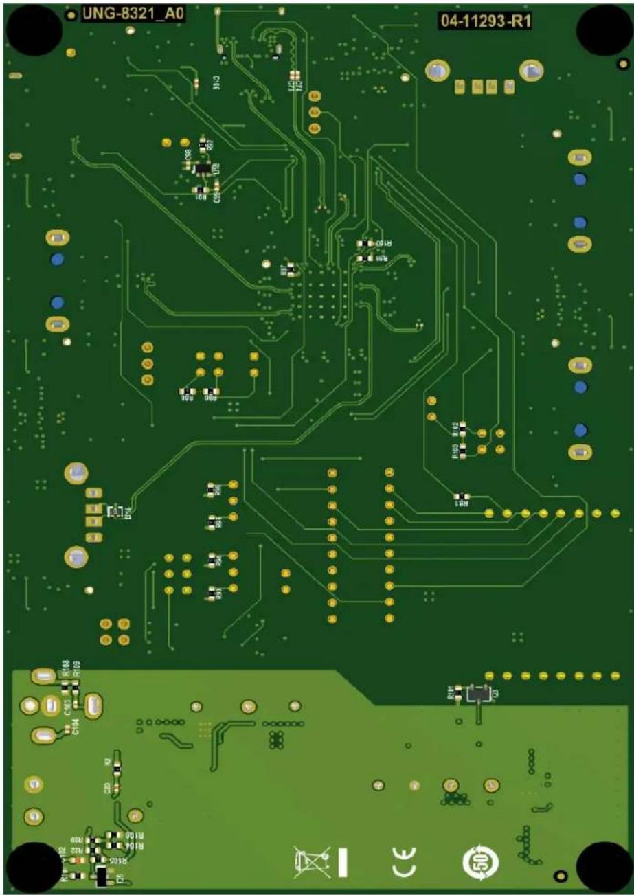
text_image
UNG-8321_A0 04-11293-R1Worldwide Sales and Service
AMERICAS
Corporate Office
2355 West Chandler Blvd.
Chandler, AZ 85224-6199
Tel: 480-792-7200
Fax: 480-792-7277
Technical Support:
http://www.microchip.com/
support
Web Address:
www.microchip.com
Atlanta
Duluth, GA
Tel: 678-957-9614
Fax: 678-957-1455
Austin, TX
Tel: 512-257-3370
Boston
Westborough, MA
Tel: 774-760-0087
Fax: 774-760-0088
Chicago
Itasca, IL
Tel: 630-285-0071
Fax: 630-285-0075
Dallas
Addison, TX
Tel: 972-818-7423
Fax: 972-818-2924
Detroit
Novi, MI
Tel: 248-848-4000
Houston, TX
Tel: 281-894-5983
Indianapolis
Noblesville, IN
Tel: 317-773-8323
Fax: 317-773-5453
Tel: 317-536-2380
Los Angeles
Mission Viejo, CA
Tel: 949-462-9523
Fax: 949-462-9608
Tel: 951-273-7800
Raleigh, NC
Tel: 919-844-7510
New York, NY
Tel: 631-435-6000
San Jose, CA
Tel: 408-735-9110
Tel: 408-436-4270
Canada - Toron
Tel: 905-695-1980
Fax: 905-695-2078
ASIA/PACIFIC
Australia - Sydney
Tel: 61-2-9868-6733
China - Beijing
Tel: 86-10-8569-7000
China - Chengdu
Tel: 86-28-8665-5511
China - Chongqing
Tel: 86-23-8980-9588
China - Dongguan
Tel: 86-769-8702-9880
China - Guangzhou
Tel: 86-20-8755-8029
China - Hangzhou
Tel: 86-571-8792-8115
China - Hong Kong SAR
Tel: 852-2943-5100
China - Nanjing
Tel: 86-25-8473-2460
China - Qingdao
Tel: 86-532-8502-7355
China - Shanghai
Tel: 86-21-3326-8000
China - Shenyang
Tel: 86-24-2334-2829
China - Shenzhen
Tel: 86-755-8864-2200
China - Suzhou
Tel: 86-186-6233-1526
China - Wuhan
Tel: 86-27-5980-5300
China - Xian
Tel: 86-29-8833-7252
China - Xiamen
Tel: 86-592-2388138
China - Zhuhai
Tel: 86-756-3210040
ASIA/PACIFIC
India - Bangalore
Tel: 91-80-3090-4444
India - New Delhi
Tel: 91-11-4160-8631
India - Pune
Tel: 91-20-4121-0141
Japan - Osaka
Tel: 81-6-6152-7160
Japan - Tokyo
Tel: 81-3-6880-3770
Korea - Daegu
Tel: 82-53-744-4301
Korea - Seoul
Tel: 82-2-554-7200
Malaysia - Kuala Lumpur
Tel: 60-3-7651-7906
Malaysia - Penang
Tel: 60-4-227-8870
Philippines - Manila
Tel: 63-2-634-9065
Singapore
Tel: 65-6334-8870
Taiwan - Hsin Chu
Tel: 886-3-577-8366
Taiwan - Kaohsiung
Tel: 886-7-213-7830
Taiwan - Taipei
Tel: 886-2-2508-8600
Thailand - Bangkok
Tel: 66-2-694-1351
Tel: 43-7242-2244-39
Fax: 43-7242-2244-393
Denmark - Copenhagen
Tel: 45-4485-5910
Fax: 45-4485-2829
Finland - Espoo
Tel: 358-9-4520-820
France - Paris
Tel: 33-1-69-53-63-20
Fax: 33-1-69-30-90-79
Germany - Garching
Tel: 49-8931-9700
Germany - Haan
Tel: 49-2129-3766400
Germany - Heilbronn
Tel: 49-7131-72400
Germany - Karlsruhe
Tel: 49-721-625370
Germany - Munich
Tel: 49-89-627-144-0
Fax: 49-89-627-144-44
Germany - Rosenheim
Tel: 49-8031-354-560
Israel - Ra'anana
Tel: 972-9-744-7705
Italy - Milan
Tel: 39-0331-742611
Fax: 39-0331-466781
Italy - Padova
Tel: 39-049-7625286
Netherlands - Drunen
Tel: 31-416-690399
Fax: 31-416-690340
Norway - Trondheim
Tel: 47-7288-4388
Poland - Warsaw
Tel: 48-22-3325737
Romania - Bucharest
Tel: 40-21-407-87-50
Spain - Madrid
Tel: 34-91-708-08-90
Fax: 34-91-708-08-91
Sweden - Gothenberg
Tel: 46-31-704-60-40
Sweden - Stockholm
Tel: 46-8-5090-4654
UK - Wokingham
Tel: 44-118-921-5800
Fax: 44-118-921-5820