N515 - PC Case In Win - Free user manual and instructions
Find the device manual for free N515 In Win in PDF.

User questions about N515 In Win
0 question about this device. Answer the ones you know or ask your own.
Ask a new question about this device
Download the instructions for your PC Case in PDF format for free! Find your manual N515 - In Win and take your electronic device back in hand. On this page are published all the documents necessary for the use of your device. N515 by In Win.
USER MANUAL N515 In Win
natural_image
Two computer monitors displaying a glowing, abstract pattern with green dots and a central blue shape (no text or symbols visible)
N515 515

text_image
QR code image with black and white pixelated pattern inside a dark rounded square border515/N515 Product Video

text_image
QR code image with black and white modules, enclosed in a dark rounded square border515/N515 Installation Video
Table of Contents Table of Conten
Product Story 04
Specifications 05
Package Contents 06
Case Structure 07
Cable Information 09
Installation Guide ....10
Notices and Warranty ......18

text_image
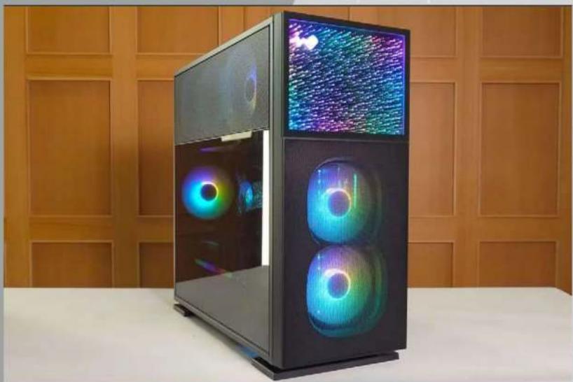
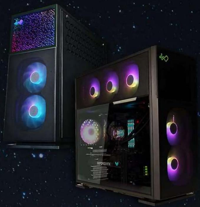
N515 515 Nebula Product Story Product StoryThe 515 is a stunning computer chassis crafted from 1.2 mm SECC steel and tempered glass. The distinctively clean panels are complemented with mesh to increase ventilation. In addition to the 515, the N515 has a front panel showing an infinite crystal universe where light extends in all directions! Both cases are prebuilt with a LUNA addressable RGB fan that will cool your system in style!
SpecificationsSpecifications
| Model 515 | N515 | |
| Model Number | IW-CS-515BLK-1AL120 | IW-CS-N515BLK-1AL120 |
| Colors Black | ||
| Case Type Mid Tower | ||
| Materials SECC, ABS, Tempered Glass | ||
| M/B Compatibility | 12” x 13” E-ATX, ATX, Micro-ATX, Mini-ITX | |
| Expansion Slots 7 x PCI-E | ||
| Maximum Compatibility | VGA Card Length: 385 mmCPU Heatsink Height: 160 mm | |
| I/O Ports | 1 x USB 3.2 Gen 2x2 Type-C2 x USB 3.2 Gen 1HD Audio | |
| Internal Drive Bays | 2 x 3.5” / 2.5”2 x 2.5” | |
| Thermal Solution Compatibility | Air Cooling Fans:Top: 3 x 120 mmRear: 1 x 120 mmBottom: 3 x 120 mmFront: 2 x 120 mm(1 InWin Luna AL120 Fan Included)Water Cooling Radiator:Top: 1 x 360 mmRear: 1 x 120 mmBottom: 1 x 360 mm (Slimm)(Remove Graphic Cards Holder)Front: 1 x 240 mm | |
* Number of fans pre-installed may vary based on different regions.
| Power Supply Compatibility | PSII: ATX12V- Length up to 200 mm |
| Product Dimensions(L x W x H) | 515 x 225 x 502 mm20.3 x 8.8 x 19.7" |
| Package Dimensions(L x W x H) | 610 x 572 x 335 mm24 x 22.5 x 13.1" |
| Net Weight 11.38 kg | 11.65 kg |
| Gross Weight 13.46 kg | 13.73 kg |
* InWin products comply with RoHS regulation.
Package ContentsPackage Co
515 Chassis N515 Chassis

natural_image
Exterior view of a black desktop computer tower case with visible internal circuitry and a colorful circular disc (no text or symbols)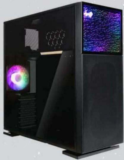
natural_image
Black desktop computer case with visible internal components and two screens displaying colorful, starry patterns (no text or symbols)QR Code Card Accessories Bag

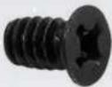
| Motherboard Stand-offs | Motherboard Stand-off Socket | Hexagon Head Screws |
 x 10 x 10 |  x 1 x 1 |  x 18 x 18 |
| 2.5" HDD Screws 3.5" HDD Screws | Water-Cooling System Washers | |
 x 18 x 18 | 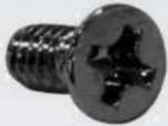 x 10 x 10 |  x 8 x 8 |
| Cable Ties Graphics Card Holders ARGB One-Click Controller | ||
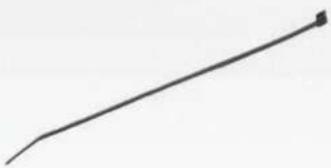 x 10 x 10 | 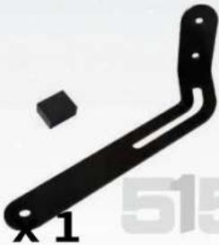 x 1 x 1 |  |
Case StructureCase Structure

text_image
e Structure Impered GlassTempered Glass
text_image
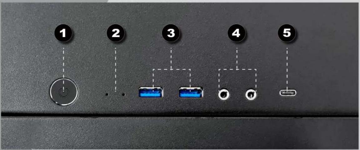
1 2 3 4 5| 1 | Power Button |
| 2 | Power/HDD LED Indicator |
| 3 | USB 3.2 Gen 1 Ports |
| 4 | dio Ports (Earphone and Microphone) |
| 5 | USB 3.2 Gen 2x2 Type-C Port |
Case Structure Case Structure

text_image
8 9 12 7 11 13 14 7 10 17
natural_image
Interior view of a computer monitor showing two labeled circular components (labeled '6') on the back panel (no text or symbols beyond labels)
natural_image
Interior view of a computer case with a circular badge labeled '15' (no readable text or symbols beyond the badge)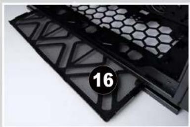
natural_image
Close-up of black plastic filter panels with hexagonal patterns and a numbered badge (16) on the right side.| 6 | 5" / 2.5" Drive Bay |
| 7 | 5" Drive Bay |
| 8 | p Fan/Radiator Mounting Area |
| 9 | ar Fan/Radiator Mounting Area |
| 10 | bottom Fan/Radiator Mounting Area |
| 11 | front Fan/Radiator Mounting Area |
| 12 | otherboard Mounting Area |
| 13 | CI-E Expansion Slot |
| 14 | graphics Card Holder Mounting Area |
| 15 | power Supply Mounting Area |
| 16 | an Dust Filter |
| 17 | nock-Proof Stand |
Cable Information Cable Infor

flowchart
graph TD
    A["POWER SW"] --> B["HDD LED"]
    B --> C["POWER LED"]
    C --> D["POWER LED"]
    D --> E["POWER LED"]
Power Switch Cable x1
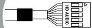
HD Audio
x1

natural_image
Pure electrical circuit lines without any symbolsUSB 3.2 Gen 1
x1

natural_image
Pure technical line drawing of a connector or connector (no text or symbols)USB 3.2 Gen 2x2 Type-C x1
ARGB Cable
x1
Installation Guide Installation
(Please follow the steps to assemble)
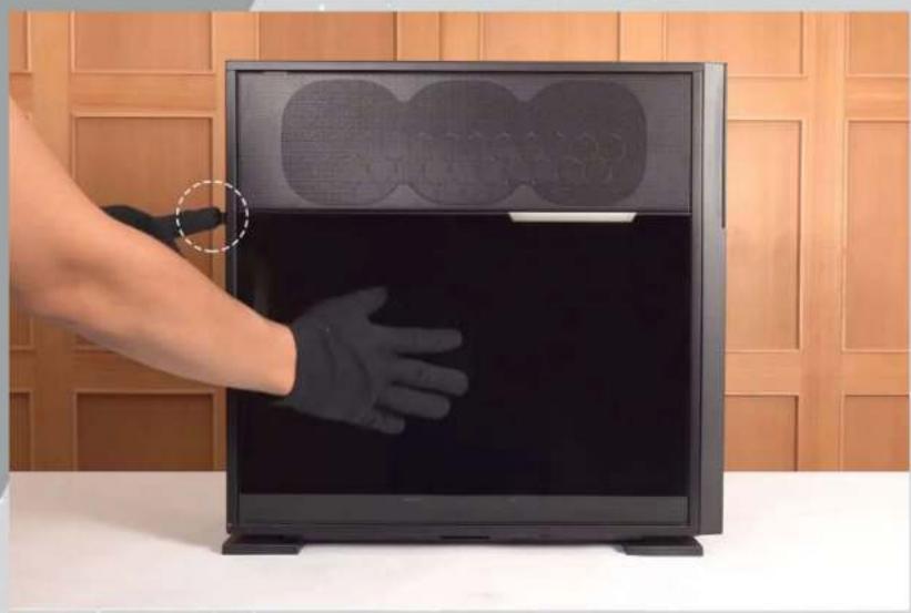
1 Opening the Glass Panel
For the Tempered Glass Panel, please remove it by pressing the rear button.
Note: You will need to remove the Tempered Glass Panel first in order to remove the Mesh Fan Grill.
natural_image
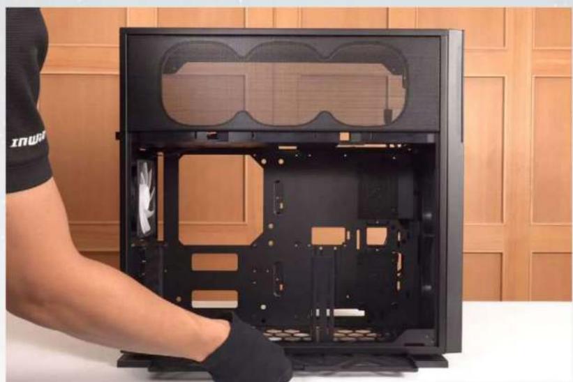
Hand holding a black glove inside a computer monitor with two circular patterns on top, against a wooden panel background (no text or symbols visible)2 Removing the Dust Filter and Graphics Card Holder
It is recommended to remove the Graphics Card Holder when installing/removing your motherboard or graphics card.
natural_image
Person assembling a black desktop computer case with visible internal components and fan (no text or symbols)
natural_image
Person in gloves handling a black hexagonal device casing against a wooden panel background (no text or symbols visible)3 Motherboard Installation
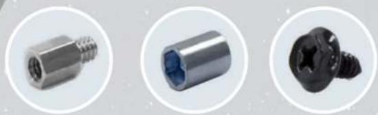
natural_image
Three metallic mechanical components shown in circular frames: threaded screw, hollow cylindrical body, and threaded screw (no text or symbols visible)Parts Required: Motherboard Stand-Offs, Motherboard Stand-Off Socket Hexagon Head Screws

natural_image
Close-up of hands installing or adjusting a black electronic device panel with a screwdriver (no visible text or symbols)4 GPU Installation

natural_image
Black metal bracket with a screw detail inset (no text or symbols visible)Parts Required: Hexagon Head Screws, Graphics Card Holder (Holder & Rubber & Bracket)


natural_image
Three-panel image showing a device interior with highlighted green and blue outlines, no visible text or symbols.Note: Use your Graphics Card Holder to support your GPU. It is adjustable to meet your needs.
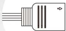
5 Opening the Front Panel
You will need to remove the Front Panel by pressing a tab to the right.
Then pull the panel from beneath with your right hand.
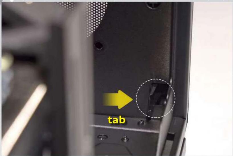
text_image
tab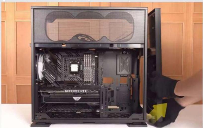
natural_image
Interior view of a GEFORCE RTX computer tower case with visible CPU socket and motherboard (no text or symbols on main body)
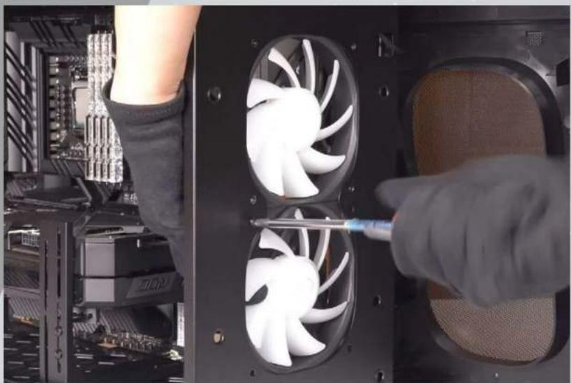
Installing Front Fans
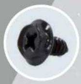
Secure the Fans with screws from the outside.

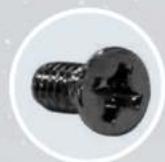
Parts Required: Fan Screws
natural_image
Close-up of hands installing a screwdriver to install a multi-core computer fan into a rack (no text or symbols visible)
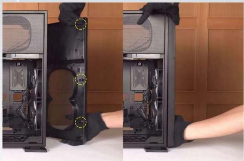
Closing the Front Panel
All crosses need to fit into the corresponding holes to fit neatly back into place.
natural_image
Two-panel photo showing a person inserting a computer tower into the case, with no visible text or symbols.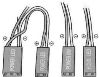
text_image
POWER LED POWER SW HDD LEDPOWER LED
(Depend On Motherboard)
POWER SW
H.D.D LED
HD Audio Header
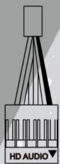
PORT2_L BLUE 10
SENSE_SEND PURPLE 8
PORT2_R YELLOW 6
PORT1_R RED 4
PORT1_L GREEN 2

natural_image
Grid pattern with geometric shapes and a black square in the center (no text or symbols)9 BROWN SENSE2_R
7 KEY
5 WHITE SNAS1_R
3 ORANGE PRESENCE#
1 BLACK GND
USB 3.2 Gen 1

natural_image
Technical line drawing of a mechanical component with mounting holes and a vertical shaft (no text or symbols)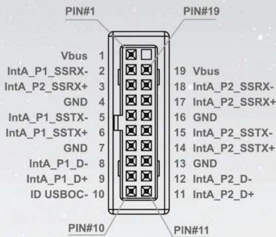
text_image
PIN#1 Vbus 1 IntA_P1_SSRX- 2 IntA_P2_SSRX+ 3 GND 4 IntA_P1_SSTX- 5 IntA_P1_SSTX+ 6 GND 7 IntA_P1_D- 8 IntA_P1_D+ 9 ID USBOC- 10 PIN#10 PIN#11 PIN#19 19 Vbus 18 IntA_P2_SSRX- 17 IntA_P2_SSRX+ 16 GND 15 IntA_P2_SSTX- 14 IntA_P2_SSTX+ 13 GND 12 IntA_P2_D- 11 IntA_P2_D+USB 3.2 Gen 2x2 Type-C

natural_image
Technical line drawing of a mechanical component with a base and top view (no text or symbols)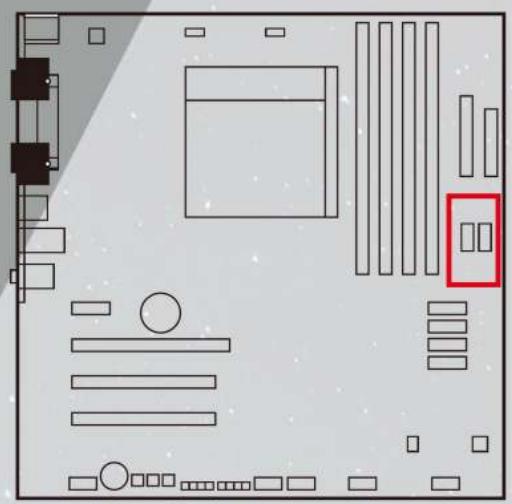
natural_image
Pure electrical circuit lines without any symbols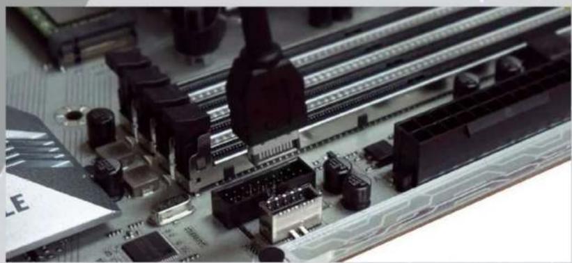
natural_image
Close-up of a computer motherboard with visible circuit breakers and connectors (no readable text or symbols)
natural_image
Close-up of a computer motherboard with electronic components and a cable inserted (no visible text or symbols)If your motherboard supports Type-C, please connect the Type-C connector with the header directly on the motherboard.
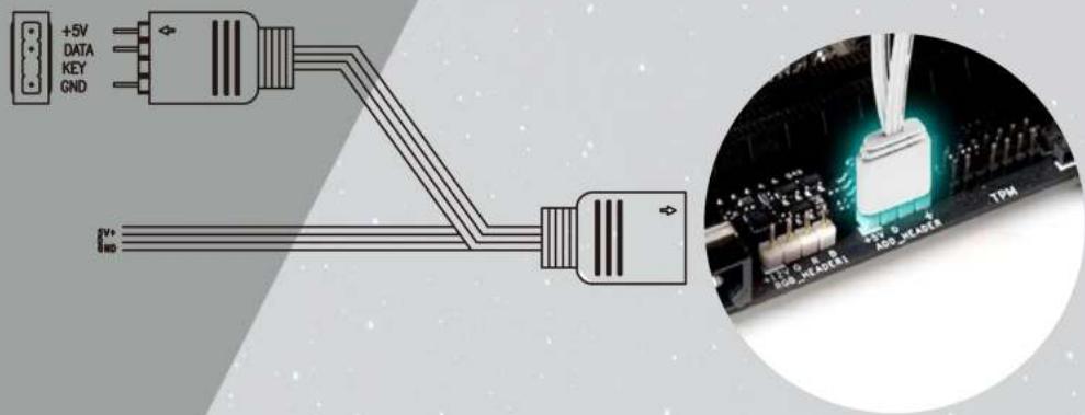
Front Panel ARGB Cable
Please choose a motherboard that supports the addressable RGB lighting effect in order to light up the LED panel. Please follow the directions of the image below and insert addressable RGB cable into the 3-pin, 5V header directly on the motherboard.
text_image
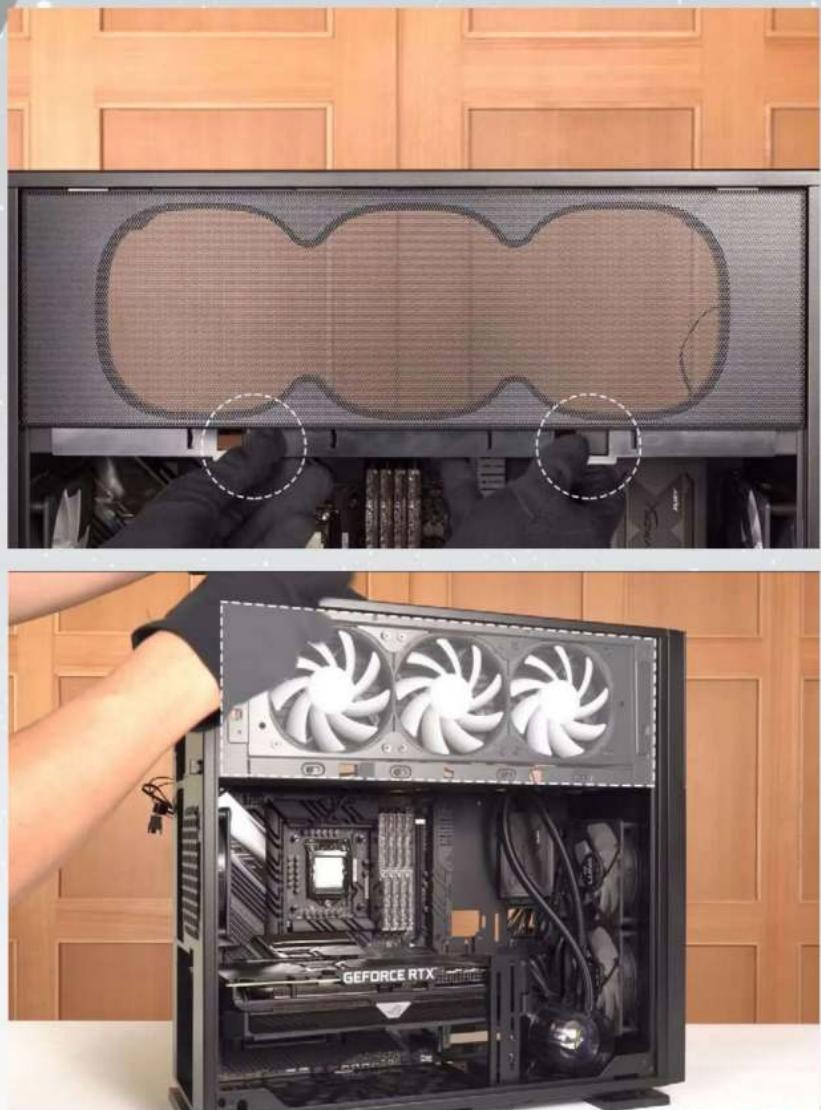
+5V DATA KEY GND 8" 100 3V ADD HEADER TPM9 Fan/Liquid Cooling Radiator Installation
To remove the side Mesh Fan Grill, lift up on the bottom tabs.
natural_image
Two-panel image showing a computer tower with a mesh screen and a close-up of the internal CPU fan assembly, both without visible text or symbols.Note: It is recommended that you choose an AIO with tubes that are around 450 mm or more in length. The InWin BR36 & NR36 AIO are examples that would fit well.
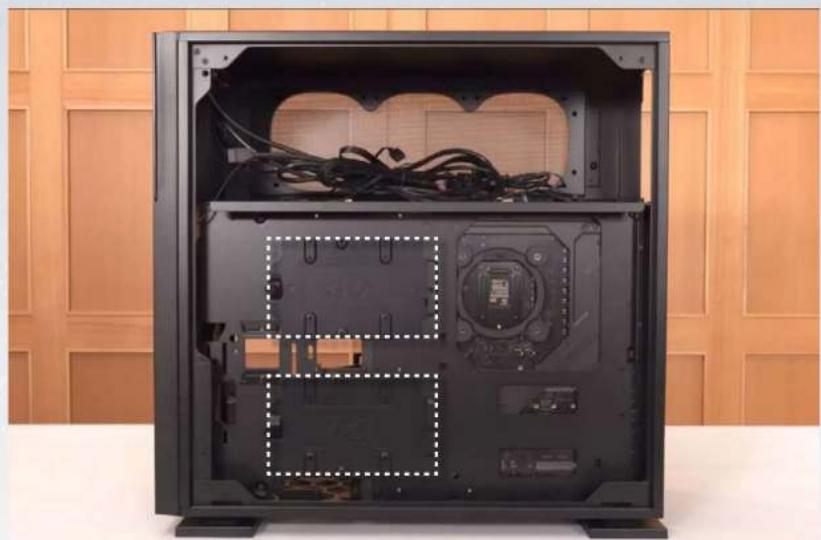
10 2.5" Drive Bay Installation
Parts Required: 2.5" HDD Screws

natural_image
Interior view of a black GEFORCE RTX desktop computer case with visible CPU socket and motherboard (no text or symbols on main body)11 3.5" Drive Bays Installation
Parts Required: 3.5" HDD Screws
natural_image
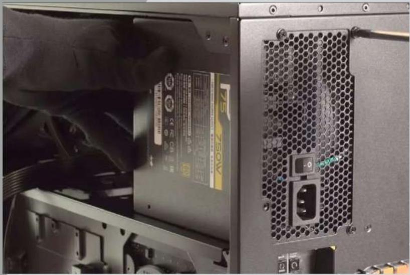
Interior view of a black desktop computer case with exposed cables and internal components, placed against a wooden cabinet background (no text or symbols visible)12 Power Supply Installation
Parts Required: Hexagon Head Screws
natural_image
Close-up of a computer tower rear panel showing power supply, drive slots, and ventilation slots (no readable text or symbols)13 Closing all Panels

natural_image
Person assembling a black desktop computer tower with three fans, no visible text or symbols on the device or background.14 Completing Installation
natural_image
Modern computer tower with dual-lens display and colorful screens, placed on a white table against a wooden panel background (no text or symbols visible)Notices and Warranty Notices
Notices
- Please follow the user manual for installation guidelines.
- When installing computer components, please use the antistatic precautions to prevent ESD (electrostatic discharge) damage. This can cause injury to the installer and/or damage to the machine. Incorrect installation may burn your motherboard and other system components.
- To avoid any damages, please do not use this product for any other purpose than its intended use.
- Any modifications may damage the product.
- Please remove all internal devices before shipping or moving. (Including power supply, hard drives, CD-ROM, motherboard and CPU, etc)
Warranty
- For more detailed warranty information, please visit the InWin retail website at www.in-win.com
- The actual product is subject to change without prior notice. In Win Development Inc. reserves the right to make any final modifications.
natural_image
Exterior view of a modern office building (no signage)
InWin
CONTEMPORARY & INNOVATIVE
www.in-win.com
