XPRO-Base-Perf-AT - Unspecified Microchip - Free user manual and instructions
Find the device manual for free XPRO-Base-Perf-AT Microchip in PDF.

User questions about XPRO-Base-Perf-AT Microchip
0 question about this device. Answer the ones you know or ask your own.
Ask a new question about this device
Download the instructions for your Unspecified in PDF format for free! Find your manual XPRO-Base-Perf-AT - Microchip and take your electronic device back in hand. On this page are published all the documents necessary for the use of your device. XPRO-Base-Perf-AT by Microchip.
USER MANUAL XPRO-Base-Perf-AT Microchip
Note the following details of the code protection feature on Microchip devices:
• Microchip products meet the specifications contained in their particular Microchip Data Sheet.
• Microchip believes that its family of products is secure when used in the intended manner and under normal conditions.
- There are dishonest and possibly illegal methods being used in attempts to breach the code protection features of the Microchip devices. We believe that these methods require using the Microchip products in a manner outside the operating specifications contained in Microchip's Data Sheets. Attempts to breach these code protection features, most likely, cannot be accomplished without violating Microchip's intellectual property rights.
• Microchip is willing to work with any customer who is concerned about the integrity of its code.
- Neither Microchip nor any other semiconductor manufacturer can guarantee the security of its code. Code protection does not mean that we are guaranteeing the product is "unbreakable." Code protection is constantly evolving. We at Microchip are committed to continuously improving the code protection features of our products. Attempts to break Microchip's code protection feature may be a violation of the Digital Millennium Copyright Act. If such acts allow unauthorized access to your software or other copyrighted work, you may have a right to sue for relief under that Act.
Information contained in this publication is provided for the sole purpose of designing with and using Microchip products. Information regarding device applications and the like is provided only for your convenience and may be superseded by updates. It is your responsibility to ensure that your application meets with your specifications.
THIS INFORMATION IS PROVIDED BY MICROCHIP "AS IS". MICROCHIP MAKES NO REPRESENTATIONS OR WARRANTIES OF ANY KIND WHETHER EXPRESS OR IMPLIED, WRITTEN OR ORAL, STATUTORY OR OTHERWISE, RELATED TO THE INFORMATION INCLUDING BUT NOT LIMITED TO ANY IMPLIED WARRANTIES OF NON-INFRINGEMENT, MERCHANTABILITY, AND FITNESS FOR A PARTICULAR PURPOSE OR WARRANTIES RELATED TO ITS CONDITION, QUALITY, OR PERFORMANCE.
IN NO EVENT WILL MICROCHIP BE LIABLE FOR ANY INDIRECT, SPECIAL, PUNITIVE, INCIDENTAL OR CONSEQUENTIAL LOSS, DAMAGE, COST OR EXPENSE OF ANY KIND WHATSOEVER RELATED TO THE INFORMATION OR ITS USE, HOWEVER CAUSED, EVEN IF MICROCHIP HAS BEEN ADVISED OF THE POSSIBILITY OR THE DAMAGES ARE FORESEEABLE. TO THE FULLEST EXTENT ALLOWED BY LAW, MICROCHIP'S TOTAL LIABILITY ON ALL CLAIMS IN ANY WAY RELATED TO THE INFORMATION OR ITS USE WILL NOT EXCEED THE AMOUNT OF FEES, IF ANY, THAT YOU HAVE PAID DIRECTLY TO MICROCHIP FOR THE INFORMATION. Use of Microchip devices in life support and/or safety applications is entirely at the buyer's risk, and the buyer agrees to defend, indemnify and hold harmless Microchip from any and all damages, claims, suits, or expenses resulting from such use. No licenses are conveyed, implicitly or otherwise, under any Microchip intellectual property rights unless otherwise stated.
Trademarks
The Microchip name and logo, the Microchip logo, Adaptec, AnyRate, AVR, AVR logo, AVR Freaks, BesTime, BitCloud, chipKIT, chipKIT logo, CryptoMemory, CryptoRF, dsPIC, FlashFlex, flexPWR, HELDO, IGLOO, JukeBlox, KeeLoq, Kleer, LANCheck, LinkMD, maXStylus, maXTouch, MediaLB, megaAVR, Microsemi, Microsemi logo, MOST, MOST logo, MPLAB, OptoLyzer, PackeTime, PIC, picoPower, PICSTART, PIC32 logo, PolarFire, Prochip Designer, QTouch, SAM-BA, SenGenuity, SpyNIC, SST, SST Logo, SuperFlash, Symmetricom, SyncServer, Tachyon, TimeSource, tinyAVR, UNI/O, Vectron, and XMEGA are registered trademarks of Microchip Technology Incorporated in the U.S.A. and other countries.
AgileSwitch, APT, ClockWorks, The Embedded Control Solutions Company, EtherSynch, FlashTec, Hyper Speed Control, HyperLight Load, IntelliMOS, Libero, motorBench, mTouch, Powermite 3, Precision Edge, ProASIC, ProASIC Plus, ProASIC Plus logo, Quiet-Wire, SmartFusion, SyncWorld, Temux, TimeCesium, TimeHub, TimePictra, TimeProvider, WinPath, and ZL are registered trademarks of Microchip Technology Incorporated in the U.S.A.
Adjacent Key Suppression, AKS, Analog-for-the-Digital Age, Any Capacitor, AnyIn, AnyOut, Augmented Switching, BlueSky, BodyCom, CodeGuard, CryptoAuthentication, CryptoAutomotive, CryptoCompanion, CryptoController, dsPICDEM, dsPICDEM.net, Dynamic Average Matching, DAM, ECAN, Espresso T1S, EtherGREEN, IdealBridge, In-Circuit Serial Programming, ICSP, INICnet, Intelligent Paralleling, Inter-Chip Connectivity, JitterBlocker, maxCrypto, maxView, memBrain, Mindi, MiWi, MPASM, MPF, MPLAB Certified logo, MPLIB, MPLINK, MultiTRAK, NetDetach, Omniscient Code Generation, PICDEM, PICDEM.net, PICkit, PICtail, PowerSmart, PureSilicon, QMatrix, REAL ICE, Ripple Blocker, RTAX, RTG4, SAM-ICE, Serial Quad I/O, simpleMAP, SimpliPHY, SmartBuffer, SMART-I.S., storClad, SQI, SuperSwitcher, SuperSwitcher II, Switchtec, SynchroPHY, Total Endurance, TSHARC, USBCheck, VariSense, VectorBlox, VeriPHY, ViewSpan, WiperLock, XpressConnect, and ZENA are trademarks of Microchip Technology Incorporated in the U.S.A. and other countries.
SQTP is a service mark of Microchip Technology Incorporated in the U.S.A.
The Adaptec logo, Frequency on Demand, Silicon Storage Technology, and Symmcom are registered trademarks of Microchip Technology Inc. in other countries.
GestIC is a registered trademark of Microchip Technology Germany II GmbH & Co. KG, a subsidiary of Microchip Technology Inc., in other countries.
All other trademarks mentioned herein are property of their respective companies.
© 2021, Microchip Technology Incorporated, All Rights Reserved.
ISBN: 978-1-5224-7671-9
For information regarding Microchip's Quality Management Systems, please visit www.microchip.com/quality.
Preface
NOTICE TO CUSTOMERS
All documentation becomes dated, and this manual is no exception. Microchip tools and documentation are constantly evolving to meet customer needs, so some actual dialogs and/or tool descriptions may differ from those in this document. Please refer to our website (www.microchip.com) to obtain the latest documentation available.
Documents are identified with a "DS" number. This number is located on the bottom of each page, in front of the page number. The numbering convention for the DS number is "DSXXXXXXXXA", where "XXXXXXXXX" is the document number and "A" is the revision level of the document.
For the most up-to-date information on development tools, see the MPLAB ^® IDE online help. Select the Help menu, and then Topics, to open a list of available online help files.
PURPOSE OF THIS GUIDE
This guide provides basic recommendations for designing products that use Microchip's XPRO rubidium oscillators. The guidelines provided are generic because specific product requirements vary from application to application.
WHO SHOULD READ THIS GUIDE
This document is intended for professionals who are designing, installing, operating, or maintaining time, frequency, and synchronization systems having a requirement for a low-profile and highly-precise frequency generator.
To use this document effectively, a good understanding of digital technologies, analog frequency generation, and synthesis techniques is helpful.
DOCUMENT LAYOUT
This guide contains the following sections:
- Chapter 1. "Functional Descriptions": Provides an overview of the product, describes the major hardware and software features, and lists the system specifications.
- Chapter 2. “Operation and Installation”: Contains the Principle of Operation, Start-Up Sequence, and aspects related to first power-up.
- Chapter 3. “Design Integration Considerations”: Provides details on the design integration considerations for the XPRO device, including thermal considerations, interfaces and grounding, and EMI considerations.
CONVENTIONS USED IN THIS GUIDE
This manual uses the following documentation conventions:
DOCUMENTATION CONVENTIONS
| Description Represents Examples | ||
| Arial font: | ||
| Italic characters Referenced books | oks MPLAB | ^ IDE User's Guide |
| Emphasized text ...is the only compiler... | ||
| Initial caps A window the Output | window | |
| A dialog the Settings dialog | ||
| A menu selection select Enable | Programmer | |
| Quotes A field name in a window or dialog | "Save project before build" | |
| Underlined, italic text with right angle bracket | A menu path File>Save | —— |
| Bold characters A dialog button | Click OK | |
| A tab | Click the Power tab | |
| N'Rnnnn | A number in verilog format, where N is the total number of digits, R is the radix and n is a digit. | 4'b0010, 2'hF1 |
| Text in angle brackets <> | A key on the keyboard | Press,, |
| Courier New font: | ||
| Plain Courier New | Sample source code | #define START |
| Filenames | autoexec.bat | |
| File paths | c:\mcc18\h | |
| Keywords | _asm, _endasm, static | |
| Command-line options | -Opa+, -Opa- | |
| Bit values | 0, 1 | |
| Constants | 0xFF, 'A' | |
| Italic Courier New | A variable argument | file.o, where file can be any valid filename |
| Square brackets [] | Optional arguments | mccl8 [options] file [options] |
| Curly brackets and pipe character: { | } | Choice of mutually exclusive arguments; an OR selection | errorlevel {0|1} |
| Ellipses... | Replaces repeated text | var_name [, var_name...] |
| Represents code supplied by user | void main (void) { ... } | |
WARNINGS, CAUTIONS, RECOMMENDATIONS, AND NOTES
Warnings, Cautions, Recommendations, and Notes attract attention to essential or critical information in this guide. The types of information included in each are displayed in a style consistent with the examples below.
WARNING
To avoid serious personal injury or death, do not disregard warnings. All warnings use this style. Warnings are installation, operation, or maintenance procedures, practices, or statements, that if not strictly observed, may result in serious personal injury or even death.
CAUTION
To avoid personal injury, do not disregard cautions. All cautions use this style. Cautions are installation, operation, or maintenance procedures, practices, conditions, or statements, that if not strictly observed, may result in damage to, or destruction of, the equipment. Cautions are also used to indicate a long-term health hazard.
Note: All notes use this style. Notes contain installation, operation, or maintenance procedures, practices, conditions, or statements that alert you to important information, which may make your task easier or increase your understanding.
WHERE TO FIND ANSWERS TO PRODUCT AND DOCUMENT QUESTIONS
For additional information about the products described in this guide, please contact your Microchip representative or your local sales office. You can also contact us on the web at www.microsemi.com/ftdsupport.
When this manual is updated the latest version will be available for downloading from Microchip's web site. Manuals are provided in PDF format for ease of use. After downloading, you can view the manual on a computer or print it using Adobe Acrobat Reader.
Manual updates are available at: www.microsemi.com/ftdsupport
RELATED DOCUMENTS AND INFORMATION
See your Microchip representative or sales office for a complete list of available documentation. To order any accessory, contact the Microchip Sales Department. See www.microsemi.com/sales-contacts/0 for sales support contact information. If you encounter any difficulties installing or using the product, contact Microchip Frequency and Time Systems (FTS) Services and Support:
U.S.A. Call Center: including Americas, Asia and Pacific Rim
Frequency and Time Systems
3870 N 1st St.
San Jose, CA 95134
Toll-free in North America: 1-888-367-7966
Telephone: 408-428-7907
Fax: 408-428-7998
email: SJO-FTD.GBUTechSupport@microchip.com
Internet: www.microsemi.com/ftdsupport
Europe, Middle East, and Africa (EMEA)
Microchip FTS Services and Support EMEA
Altlaufstrasse 42
Microchip provides online support via our website at www.microchip.com. This website is used as a means to make files and information easily available to customers.
Accessible by using your favorite Internet browser, the website contains the following information:
- Product Support – Data sheets and errata, application notes and sample programs, design resources, user's guides and hardware support documents, latest software releases and archived software
- General Technical Support – Frequently Asked Questions (FAQs), technical support requests, online discussion groups, Microchip consultant program member listing
- Business of Microchip – Product selector and ordering guides, latest Microchip press releases, listing of seminars and events, listings of Microchip sales offices, distributors and factory representatives
CUSTOMER SUPPORT
Users of Microchip products can receive assistance through several channels:
• Distributor or Representative
- Local Sales Office
• Field Application Engineer (FAE)
- Technical Support
Customers should contact their distributor, representative or field application engineer (FAE) for support. Local sales offices are also available to help customers. A listing of sales offices and locations is included in the back of this document.
Technical support is available through the website at:
http://www.microchip.com/support.
DOCUMENT REVISION HISTORY
Revision A (February 2021)
- Initial release of this document as Microchip DS50003049A.
Table of Contents
Preface 3
Purpose of This Guide.... 3
Who Should Read This Guide.... 3
Document Layout 3
Conventions Used in this Guide 4
Warnings, Cautions, Recommendations, and Notes...... 5
Where to Find Answers to Product and Document Questions .... 5
Related Documents and Information.... 5
The Microchip Website....6
Customer Support 6
Document Revision History 6
Chapter 1. Product Overview
1.1 Typical Applications....9
1.2 Specifications 10
1.2.1 XPRO Electrical Specifications.... 10
1.2.2 XPRO Connectors ...... 11
1.2.3 XPRO MTBF: Ground Benign (GB) Prediction.... 12
Chapter 2. Operation and Installation
2.1 Theory of Operation 13
2.2 Installation 14
2.2.1 Site Selection 14
2.2.2 Cabling 14
2.2.3 Turn-On Procedure 14
2.2.4 Frequency Adjustment Procedure 15
2.2.5 Synchronizing to an External 1PPS Signal .... 16
2.2.6 Maintenance and Repairs ...... 16
Chapter 3. Design Integration Considerations
3.1 XPRO Mechanical Drawings 17
3.2 Thermal Considerations ...... 17
3.2.1 Thermal Tape Use.... 17
3.2.2 Heat Sink 17
3.2.3 Impact of External Ambient Air Temperature on Unit Operation 17
3.2.4 Unit Operating Temperature Range 18
3.2.5 Frequency Offset from Water Condensation....19
3.3 External Interfacing and Grounding.... 19
3.3.1 XPRO Serial Port Protocol 20
3.3.2 Lock (BITE) Signal 21
3.3.3 Service Signal 21
3.3.4 Frequency Control 21
XPRO User's Guide
3.4 Temperature Compensation of Frequency.... 21
3.5 EMI Considerations.... 22
3.5.1 Outer Mu-Metal Cover 22
3.6 XPRO Susceptibility to Input Noise.... 22
3.7 XPRO Maintenance.... 23
3.7.1 XPRO Design Goal 23
Worldwide Sales and Service 25
Chapter 1. Functional Descriptions
The XPRO is part of Microchip's family of precision frequency generator components. It is designed to easily integrate into a system, requiring only one input supply voltage and allowing direct plug-in connection into another circuit board. It offers the reliability of a design that has been refined over many years from the experience gained in fielding tens of thousands of Microchip oscillators.
The following illustration shows the XPRO high-performance rubidium oscillator.

text_image
MICROCHIP XPRO Rubidium Oscillator Part Number: Serial Number: *16192-001* *1408XP1164* J4 1 24L/ RPN 10MHz Single 2 IPPS SYNC 3.0 Out 4.0 P 5 LOCKBITE 6 7 8 9 J1 8-24L/ IPPS Out Slamola 9 PMI OffFIGURE 1-1: XPRO High-Performance Rubidium Oscillator.
1.1 TYPICAL APPLICATIONS
The XPRO is a product that Microchip offers for those who require a high-performance rubidium atomic frequency standard in their system design. The XPRO is designed for ease of integration into time and frequency systems because of its low-profile and single-circuit board design. The height and footprint are designed to accommodate a 1U VME application, or a 3U VME application. Great care has been taken in the design to minimize EMI emissions and susceptibility, including the use of an outer mu-metal cover. The XPRO complies with the FCC Article 47, Code of Federal Rules, Part 15, Class B. The operation is subject to the following two conditions.
- This device may not cause harmful interference.
- This device must accept any interference received, including interference that may cause undesired operation.
The XPRO also complies with EN55022B and EN50082-1. For more information, see the XPRO data sheet.
The technology utilized in the design of the XPRO has been successfully applied to telecom networks, such as digital cellular/PCS base stations, SONET/SDH digital network timing, and aerospace and defense applications (such as secure communications systems and satellite ground-stations). Linked with a GPS receiver, the XPRO provides the necessary timing requirements for CDMA cellular and PCS systems. The low-temperature coefficient and excellent frequency stability extend holdover performance when the GPS signal is not available.
The XPRO is designed for long operating periods without maintenance (long-life Rb lamp, extended crystal control range) with a goal to exceed 10 years. The design provides a stable frequency with good short- and long-term stability, and excellent spur performance.
The XPRO provides a 5V CMOS-compatible alarm signal derived from the basic physics operation, which indicates when the output frequency is outside roughly ±5 × 10^-8 of absolute frequency offset.
1.2 SPECIFICATIONS
The following sections provide details on the specifications for the XPRO device.
Note: This information is subject to change. Consult the XPRO data sheet for the most up-to-date list of specifications.
1.2.1 XPRO Electrical Specifications
The following are outputs for the XPRO electrical specifications.
• 10 MHz Sine Wave
- Level: 7.8 dBm ±0.8 dBm (0.55V RMS ±0.05V RMS )
- Impedance load: 50Ω
• 1 P P S
- Polarity: Positive
- Pulse width: 20 μs
- Rise/fall time: ≤5 ns (with a 15 pF load)
- Logic level: VL < 0.55V, VH > 4.2V (with a 15 pF load)
- RMS jitter: ≤1 n s
- JamSync accuracy: 10 ns
- Lock status (BITE) 5V CMOS
- Lock: 0V to <0.55V
- Unlock: 4.2V to 5V
• Service status 5V CMOS
- Low: 0V to <0.55V
- High: 4.2V to 5V
The following are inputs for the XPRO electrical specifications.
- 1PPS Sync
- V_IL : 0V to 0.8V
• Analog range (±1.5 × 10 ^-9 )
- 0V_DC to 5V_DC
- Input voltage range
- 19V_DC to 32V_DC
RS-232 control/monitor interface
Note: Voltage levels are 3.3V CMOS. A “level-shift” device should be employed to achieve true RS-232 levels.
- Baud rate: 57,600
- Data bits: 8
- Parity: None
- Stop bits: 1
- Flow control: None
1.2.2 XPRO Connectors
The following illustration shows the J1 connector.
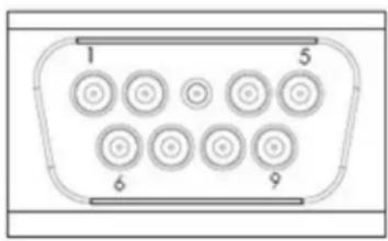
text_image
1 5 6 9FIGURE 1-2: J1 Connector.
The following table lists the J1 signals.
TABLE 1-1: J1 SIGNALS
| Pin Number | Signal Name Type | Signal Function | |
| 1 24V | RTN GND Power return to chassis ground | ||
| 2 1PPS IN — | Sync to external 1PPS input | ||
| 3 | SERIAL DATA OUT | 3.3V CMOS | Digital steer and control |
| 4 | SERIAL DATA IN | 3.3V CMOS | Digital steer and control |
| 5 | LOCKBITE | 5V CMOS | Indication of lock status |
| 6 | 24V_DC | PWR | Power input |
| 7 | 1PPS OUT | 5V CMOS | 1PPS output |
| 8 | SERVICE | 5V CMOS | Indication of service status |
| 9 | FREQCTL | DC | Analog steer |
The following illustration shows the J4 connector for the 10 MHz sine output (SMA FEMALE, MIL-PRF-39012).
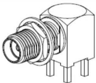
natural_image
Technical line drawing of a mechanical component with threaded body and mounting feet (no text or symbols)FIGURE 1-3: J4 Connector.
1.2.3 XPRO MTBF: Ground Benign (GB) Prediction
The following table lists the predicted mean time between failure (MTBF) for the XPRO in a ground benign (GB) environment.
TABLE 1-2: XPRO PREDICTED MTBF, GB
| Temperature XPRO MTBF XPRO MTBF | |
| 20°C 950,976 hours 109 years | |
| 25°C 808,510 hours 92 years | |
| 30°C 679,036 hours 78 years | |
| 35°C 536,669 hours 64 years | |
| 40°C 462,792 hours 53 years | |
| 45°C 376,112 hours 43 years | |
| 50°C 302,799 hours 35 years | |
| 55°C 241,655 hours 28 years | |
| 60°C 191,277 hours 22 years |
Chapter 2. Operation and Installation
The following sections describe the operation and installation of the XPRO device.
The XPRO makes use of the atomic-resonance property of rubidium ( ^87Rb ) to control the frequency of an unheated voltage-controlled crystal oscillator (VCXO) through a frequency-locked loop (FLL).
The following illustration shows a simplified function block diagram for the FLL.

flowchart
graph TD
    A["Microwave VCO 3.4 GHz"] --> B["X"]
    B --> C["a"]
    C --> D["Rb Cell"]
    D --> E["I to V"]
    E --> F["Digital Demodulator"]
    F --> G["Modulation Source"]
    H["Power Detector"] --> C
    I["Rb Lamp"] --> D
    J["SSB X"] --> K["Offset PLL"]
    K --> L["Low-Pass Filter"]
    M["DDS"] --> N["÷"]
    O["VCXO 20 MHz"] --> N
    N --> P["Integrator"]
    P --> F
FIGURE 2-1: XPRO Simplified Function Block Diagram.
A microwave signal is derived from a 20 MHz VCXO and applied to the ^87Rb vapor within a glass container or cell. The light of a rubidium spectral lamp also passes through this cell and illuminates a photo detector. When the frequency of the applied RF signal corresponds to the frequency of the ground-state hyperfine transition of the ^87Rb atom (an ultra-stable high-Q rubidium atomic resonator), light is absorbed causing a change (decrease) in photo detector current ( I_PH ).
As the change in current is small, modulation techniques are required to extract the desired signal out of the noise background.
The dip in photo detector current is used to generate a control signal with phase and amplitude information, which permits continuous atomic regulation of the VCXO frequency. The servo section converts the photo detector current into a voltage, then amplifies, digitizes, demodulates, and integrates it for high DC-servo loop gain.
The VCXO output signal is divided by two and is buffered to provide the standard frequency output at 10 MHz. This signal is also frequency multiplied to microwave at 6.8346875 GHz through an offset locked phase lock loop (PLL) to interrogate the rubid-
ium reference. The offset frequency is generated by a high-resolution direct digital synthesizer (DDS) for tuning ability and the microwave power level is servo controlled to minimize frequency instability caused by microwave power fluctuations.
2.2 INSTALLATION
The following sections provide details on installation for the XPRO device.
2.2.1 Site Selection
The XPRO installation site should be selected to maintain supply voltage and baseplate temperatures in the product specifications range.
Make sure there are no strong magnetic fields at the site because XPRO is sensitive to external DC- and AC-magnetic fields (see Section 1.2 "Specifications"). An external magnetic field under 2 gauss should not result in measurable permanent frequency offsets for XPRO.
2.2.2 Cabling
If desired, the XPRO is designed to directly mate to a user's interface board, saving the cost and associated issues of interconnect cabling.
Note: Always use shielded cable and connectors to minimize EMI emissions.
2.2.3 Turn-On Procedure
The XPRO does not have an on/off switch. The unit is powered up by plugging in the unit's J1 connector to a properly terminated cable or the user's interface board. The following illustration shows a block diagram of a suggested hookup.
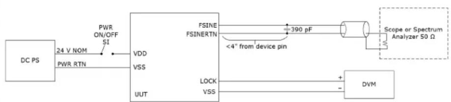
flowchart
graph LR
    A["DC PS"] -->|24 V NOM PWR RTN| B["VDD"]
    B --> C["VSS"]
    C --> D["UUT"]
    D --> E["FSINE FSINERTN"]
    E --> F["390 pF"]
    F --> G["Scope or Spectrum Analyzer 50 Ω"]
    E --> H["LOCK VSS"]
    H --> I["DVM"]
    I --> J["+"]
    I --> K["-"]
FIGURE 2-2: Block Diagram of Suggested XPRO Hookup.
The mating connector must provide power to J1-6 and power return to J1-1. The system power supply must be capable of providing a peak source current of >1.5A during the warm-up period. After warm-up, this power requirement drops to \~0.5A (room temperature).
If the power supply is unable to provide the required peak amperage, then the XPRO warm-up times will be degraded. If insufficient power is provided, the unit may be unable to complete warm-up and a latch-up condition will result. This does not over stress the electronics of the unit. However, it prevents the unit from achieving lock. It can also cause rubidium migration in the lamp, which could prevent the unit from operating properly (it would require servicing).
The following are steps for turning on the XPRO:
- Connect the RF load to the SMA female connector, J4.
- Monitor the BITE signal at J1-5 with respect to chassis ground at J1-1, using a high-impedance meter (recommended >1 MΩ input resistance).
- Once the XPRO is plugged in and receiving power, wait 3 to 6 minutes while the unit achieves atomic lock. During this period, the monitored BITE signal should
be HIGH (4.2V DC to 4.8V DC ). Once the unit achieves atomic lock, the BITE signal goes LOW (<50 mV with respect to GND). At this point, the output frequency should be approximately ±5×10^-8 of absolute frequency.
- Thirty minutes after applying power to the XPRO, the RF output frequency will be very close to full accuracy (for more information about accuracy versus time from turn on, see the XPRO data sheet).
Note: The output frequency of the XPRO is more accurate than most counters. Contact your local sales representative for appropriate measurement equipment.
2.2.4 Frequency Adjustment Procedure
There are two primary reasons to adjust the external frequency output of the XPRO. The first is to compensate for aging over time, and the second is to synchronize the rubidium oscillator to a more accurate primary frequency source. The XPRO is considered to be a secondary frequency standard (it is more accurate than a quartz frequency standard, but not as accurate as a cesium standard, which is considered to be a primary standard). By synchronizing the XPRO's rubidium oscillator to an external cesium clock, or GPS satellite, it can be readjusted periodically to match the primary standard's slower aging rate and greater accuracy.
There are two mechanisms to adjust the output by the user. Both methods result in a change of the DDS frequency, which induces a change in the output frequency at 10 MHz.
The first method is to apply an analog voltage to the frequency control pin J1-9. The pin can accept a voltage range from 0V_DC to 5V_DC , which produces a linear change in the offset frequency. A voltage input of 0V will result in a -1.5 × 10^-9 offset, while a voltage input of 5V will result in a 1.5 × 10^-9 , and a voltage input of 2.5V will result in no change of the frequency offset.
CAUTION
It is recommended to only apply voltages within this range. Voltages outside of this range can lead to a latch-up condition of the internal A/D converter or lead to potential damage of the unit.
The second method is to directly change the DDS frequency count through a RS-232 serial port command. The user is allowed to apply a digital-calibration offset change or a digital-discipline offset change, both up to ±1.0×10^-6 . The calibration change allows an offset correction to the XPRO, which can be later saved into the non-volatile memory. By using the
Note: The
Using an external counter suitable for the task (this operation requires a measurement accuracy that exceeds most counters), adjust the unit so that the output RF frequency is 10,000,000.000 Hz.
2.2.5 Synchronizing to an External 1PPS Signal
The following steps show how to synchronize to an external 1PPS signal.
- Wait for clock to lock (see Lock (BITE) Signal (see page 13)).
- Connect external 1PPS in (see XPRO Connectors (see page 5)).
- Send command J (see XPRO Serial Port Protocol (see page 12)).
2.2.6 Maintenance and Repairs
The XPRO is not field repairable. If the unit should fail, do not remove the cover of the unit and attempt to make repairs. Instead, call Microchip for the return procedure from the Customer Support Group before returning the unit to Microchip.
Chapter 3. Design Integration Considerations
The following sections provide details on the design integration considerations for the XPRO device.
3.1 XPRO MECHANICAL DRAWINGS
The following illustration shows the XPRO mechanical drawing.
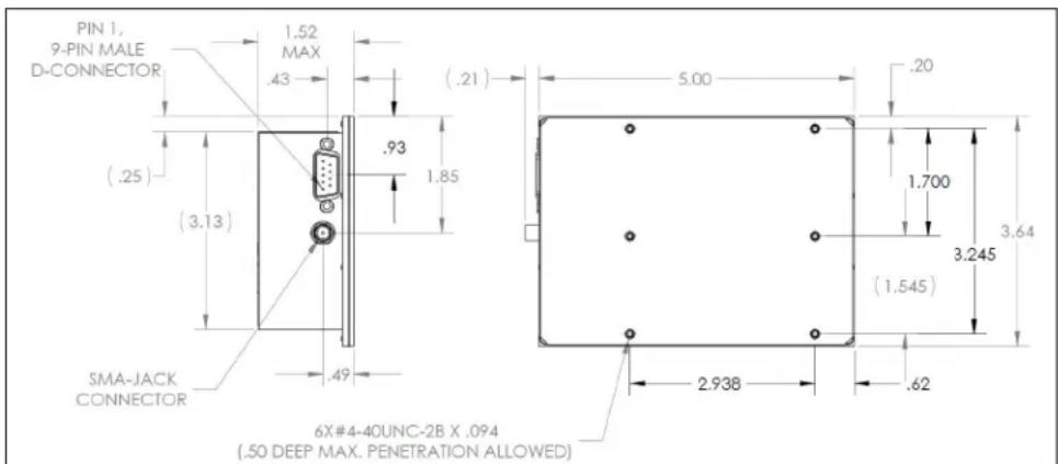
text_image
PIN 1, 9-PIN MALE D-CONNECTOR .52 MAX .43 (.21) .93 1.85 (.25) (3.13) SMA-JACK CONNECTOR .49 5.00 .20 1.700 3.64 (1.545) 3.245 2.93B .62 6X#4-40UNC-2B X .094 (.50 DEEP MAX. PENETRATION ALLOWED)FIGURE 3-1: XPRO Mechanical Drawing.
3.2 THERMAL CONSIDERATIONS
The following sections describe the thermal considerations for the XPRO device.
3.2.1 Thermal Tape Use
It is critical to obtain a good thermal contact from the bottom (baseplate) of the XPRO to the mounting surface in order to achieve the highest ambient operating temperature for the specified XPRO operating baseplate temperature. It is also very important to maintain a uniform heat sink temperature because of uneven heat flow into the base-plate of the XPRO through its various mounting points.
3.2.2 Heat Sink
A heat sink or mounting baseplate is required to keep the baseplate temperature under 70^ C. Internal self heating of the XPRO will cause local internal temperatures to exceed Microchip's part de-rating guidelines when used without a heat sink or forced air (although the maximum manufacturer's operating temperature ratings will not be exceeded). A heat sink with thermal resistance to ambient of less than 2^ C/W is required for ambient of 50^ C maximum.
3.2.3 Impact of External Ambient Air Temperature on Unit Operation
The power consumption for XPRO versus baseplate temperature is dominated by the following mechanisms.
• The resonator heater power
• The lamp heater power
• The electronics power
The resonator heater power is determined primarily by the resonator control temperature of 82^ C, the baseplate temperature, and the 15.3^ C/W thermal resistance from the resonator to baseplate. The lamp heater power is determined primarily by the lamp control temperature of 114^ C, the baseplate temperature, and the 53^ C/W thermal resistance from the lamp to baseplate. Due to the unit's internal 17V regulator, the electronics power reflects a fixed electronic current that is independent of input voltage. It is roughly independent of baseplate temperature. The heater powers are roughly independent of input voltage.
The XPRO maximum baseplate temperature described in the specifications was based on a model where the unit was covered on 5 sides with 1-inch foam to simulate free convection in air as the heat sink/baseplate was exposed to forced air.
The maximum operating baseplate temperature will be lower by several degrees Celsius if the external air is hotter than the baseplate mounting. For example, a situation where the baseplate is being cooled by a thermoelectric cooler, but the unit is exposed to nearby heat-producing equipment.
If there is air flow over the unit's top cover, the XPRO's maximum operating baseplate temperature will increase by 1^ or 2^ and its power consumption at a given baseplate temperature will also increase by a few tens of milliwatts.
3.2.4 Unit Operating Temperature Range
There are three scenarios of interest concerning the operating temperature range for XPRO (operating range -25^ to +70^ baseplate).
These three scenarios are differentiated by performance for the following conditions:
• The turn-on/warm-up period
- Standard operation after warm up is completed
- Emergency operation after warm up is completed
The turn-on/warm-up period includes the time for the internal heater circuits to obtain thermal equilibrium, for the lamp to ignite into a plasma discharge, for the standard to achieve atomic lock, and for the crystal operating temperature to reach its normal operating temperature range.
The following are the three scenarios:
- Scenario 1: The operating temperature range below the normal temperature range without guaranteed warm up, but with full frequency control. Not recommended and performance/specifications are not guaranteed.
- Scenario 2: The normal temperature range with full performance, including warm up.
- Scenario 3: The operating temperature range above the normal temperature range, excluding guaranteed warm up, but without loss of lock. Not recommended and performance/specifications are not guaranteed.
The following describe all scenarios defined in terms of the unit's baseplate temperature (the bottom surface of the bottom cover):
- Scenario 1 (not recommended) Temperature Range: -35^ to -25^ baseplate. This operating temperature range allows full-frequency control, but excludes normal warm up. The cold-temperature limit is based on the use of a -30^ / +85^ unheated crystal, and an internal temperature rise at the crystal of 6^ .
- Scenario 2 Temperature Range: -25^ to +70^ baseplate. The normal operating temperature range with specified warm-up capability included. This temperature range excludes that of scenario 1, because of the unheated crystal used in the
XPRO. The unit will not be damaged when operated between -35^ and -30^ , but a guaranteed performance cannot be ensured until the circuit board near the crystal begins to warm; a 6^ rise occurs thirty minutes to one hour after turn on.
- Scenario 3 (not recommended) Temperature Range: +70^ to +75^ baseplate. This is the emergency operating temperature range that maintains lock (but has no guaranteed warm-up period). The hot-temperature limit is based on staying under the maximum operating temperature of the crystal, avoiding loss of thermal control of the resonator heater, and not exceeding the operating de-rating guidelines of selected XPRO components. This condition is not recommended for a long operating period because once heater control is lost, the unit may take on a frequency offset (typically parts in 10^-11 ) that will be present for many days of operation while the unit returns to equilibrium. Also, Microchip part de-rating guidelines are exceeded under this condition, although the component manufacturer's maximum part rating guidelines are not, provided the baseplate temperature is kept below +75^ .
When thermal control is lost, the result is a large rate of change of frequency versus temperature. As the baseplate temperature increases, the unit will eventually lose lock, as seen in the Theory of Operation (see page 7). The physics package acts as a discriminator that compares the injected microwave frequency to the hyperfine transition frequency of ^87Rb (6.834687500 GHz). The output signal drops rapidly as the resonator temperature increases above the set point. When the output signal drops low enough, the unit can no longer maintain internal lock. When the resonator or lamp heaters shut down because no power is required to sustain control point temperatures, the unit temperature coefficients are about 5 × 10^-10/^ temperature change.
3.2.5 Frequency Offset from Water Condensation
Condensation of moisture from the air onto electrical components will produce frequency spikes or instability until the heat of the operating unit drives out the water vapor. Condensation is more of a problem when a cold unit is warming up rapidly because the temperature of the internal surfaces of the XPRO will lag the temperature changes of the outside ambient air, and an influx of hot, humid air will hold enough moisture to condense out on the colder surfaces.
Condensation will not cause a problem for environments meeting the XPRO specification if the XPRO baseplate thermal ramp rates are controlled so that they rise at less than 2^ C/minute.
3.3 EXTERNAL INTERFACES AND GROUNDING
The XPRO is constructed with the chassis (unit cover) and signal grounds tied together at multiple points, and with the power supply return isolated from both chassis and signal grounds only by a ferrite bead. This robust grounding approach allows for ESD protection and low spurious emissions. But it can also lead to ground loop issues.
Workarounds commonly used to break DC-ground loops at a higher level of integration are to isolate the XPRO cover/chassis from the user's chassis, use an RF-isolation transformer for the 10 MHz RF output, and/or float the transformer secondary winding of the user's power supply.
The J1 signals are routed through filter capacitors selected for EMI and ESD purposes. The 10 MHz RF output uses an SMA female-coax connector, which when connected, provides shielding of the RF from EMI and ESD.
3.3.1 XPRO Serial Port Protocol
The XPRO utilizes RS-232 serial port communications to allow control of the unit's output as well as to poll the unit for data related to its health and operating status. The following sections describe the configuration, protocol, and ASCII command structure used to communicate with the XPRO.
Note: Voltage levels are 3.3V CMOS. A "level-shift" device should be employed to achieve true RS-232 levels.
3.3.1.1 SERIAL PORT CONFIGURATION
The XPRO requires the RS-232 serial port to be set to the following protocol.
• Baud Rate: 57600
- Data Bits: 8
- Parity: none
- Stop bit: 1
- Hardware flow: none
3.3.1.2 COMMAND STRUCTURE BASICS
The XPRO supports the following two types of commands.
- Single-keystroke commands, without the need of a carriage return.
- Multi-keystroke commands, which require a specific first “<” and last “>” character. This structure is used for commands that require a payload. It is imperative to always close the payload command with the “>” character, even if a keystroke mistake is made, to avoid communication hang-up.
For unrecognizable or unavailable commands, the unit will respond one of two ways.
- For commands with an ASCII code below 128, the unit will ignore the command except to respond with a “?” character.
- For commands with an ASCII code of 128 or above, the unit will ignore the command and produce no response.
3.3.1.3 XPRO COMMANDS
The following table lists the commands used for the XPRO.
TABLE 3-1: XPRO COMMANDS
| Command Description | |
| C Displays a list of current parameter values in raw count values. | |
| c Displays a list of current parameter values in specified SI units. | |
| n Displays a list of the unit's non-volatile stored parameters in raw count values. | |
| ! Displays a list of status parameters in their appropriate numerical and text formats. | |
| | Displays the build date of the unit's firmware. | |
| { Displays a comma delimited string of text headers for current parameter values. | |
| } Displays a comma delimited string of data for current parameter values. | |
| [ Displays a comma delimited string of text headers for non-volatile stored parameter values. | |
| ] Displays a comma delimited string of data for non-volatile stored parameter values. | |
| A Enables the analog tuning function. | |
| a Disables the analog tuning function. | |
| J Enables the 1PPS JamSync command sequence. | |
| Adjusts the calibrated output frequency, where ±dddd represents a delta frequency number in 10^-12 Hz/Hz. | |
| Saves the calibrated output frequency to non-volatile storage. | |
Note: For more information on
3.3.2 Lock (BITE) Signal
The lock (BITE) signal indicates that the internal VCXO is locked to the atomic transition. If after warm-up is completed, the BITE signal is LOW, the output frequency is locked to the Rb atomic clock.
If the BITE signal is high, the atomic lock has been lost, and the XPRO goes into sweep mode to reacquire lock. The sweep ranges from approximately -21 ppm to 21 ppm in approximately a 20-second period. During the sweep, outputs are maintained, but signal accuracy is unreliable until BITE signal returns to a low state.
If the power source to the XPRO is off, the lock output line is low.
3.3.3 Service Signal
The service signal is valid when the unit is operating, and the rubidium oscillator is locked.
The service signal algorithm monitors the health of the Rb physics package, which includes the Rb lamp bulb, resonator cell, and the unit's crystal oscillator that is targeted by the Rb atomic clock.
The service signal indicates low (configurable to low or high) when any of the internal operating parameters are near the end of their tuning or adjustment range. This warning provides \~1 month of operation before a failure becomes imminent.
3.3.4 Frequency Control
The frequency can be either analog or digitally controlled, depending on the application. The analog control can be enabled or disabled at the factory (making it a default setting), or by the customer at a later date (using the serial port control interface). The digital control is enabled at the factory and is not customer configurable.
When in use, the smallest incremental frequency change is 2 × 10^-12 (or f.2). The unit always powers up to the preset free running factory set frequency. Analog and digital calibration adjustments are always relative to the current free running frequency of the unit. Digital discipline adjustments are absolute frequency adjustments of the free running frequency.
3.4 TEMPERATURE COMPENSATION OF FREQUENCY
One of the key specifications for an atomic frequency standard is the temperature coefficient. The XPRO is designed for a low temperature coefficient without the need for temperature correction. However, in applications where the user requires a tighter temperature coefficient, a common practice is to monitor the base-plate temperature of the XPRO and apply a correction signal through the analog or digital control method.
This method can be successfully used for moderate correction, for example, to bring the maximum frequency change over the full-operating temperature range to less than 1 × 10^-10 . Applying more correction is possible, but there are limits without issues for both yield loss and the test time required for correction, as one runs into the inherent problems of subtracting two large numbers to accurately and consistently obtain a small difference.
Compensation using this scheme is suitable only for steady-state conditions. This is because of inherent mismatches between the thermal time constants of the mechanisms that cause temperature coefficient errors, and because of the thermal time constant of the monitoring circuitry. Transients from time constant mismatches will show up. These transients are minimized if temperature ramp rates are limited. Changing less than 2^ C/minute baseplate temperature should result in negligible transients from mismatches.
3.5 EMI CONSIDERATIONS
The following section describes the EMI considerations for the XPRO device.
3.5.1 Outer Mu-Metal Cover
The resonator packages of rubidium frequency standards have significant frequency offsets when external magnetic fields are present. For this reason, it is customary to use a double mu-metal shield for the resonator housing in order to meet the magnetic susceptibility specification for the unit of parts in 10^-11/gauss .
The XPRO was designed so that the unit cover forms the second, outer-magnetic shield. The cover is made of mu-metal, with overlapping edges that minimize problems with fringing fields. The advantage of this approach is the resulting magnetic shielding of the electronics outside of the resonator package.
3.6 XPRO SUSCEPTIBILITY TO INPUT NOISE
When a user has an application where the output spectrum phase noise and spur integrity is crucial, the XPRO must be provided with comparatively clean source of DC power (free of spurious current or voltage noise). Connecting fans and other electro-mechanical devices to the DC supply powering the XPRO can result in degraded phase noise and spur performance. This is because motors with brushes can create a wide spectrum of noise. The frequency spectrum of the spurs will vary largely with the motor's speed and load conditions.
The Rb atomic frequency source uses a modulation/demodulation lock-in amplifier scheme with a modulation frequency of 152 Hz. Inherent in this approach is sensitivity to noise at multiples of the modulation frequency. This noise is coupled through both the heater and electronic power lines to cause modulation spurs on the output frequency.
CAUTION
Care should be taken to avoid the modulation frequency and its harmonics up to roughly the tenth harmonic.
The XPRO has an internal linear regulator supplying power to the critical electronics, including the crystal oscillator, which is the source for the 10 MHz output. This regulator loses its ripple rejection attributes at frequencies greater than 100 kHz. The crystal oscillator in the unit has some filtering to minimize the conductive spurs from affecting the oscillator. It remains critical that a clean input supply is used if spur and phase-noise performance is critical for the end-user application.
3.7 XPRO MAINTENANCE
The following section provides details on the XPRO maintenance.
3.7.1 XPRO Design Goal
The XPRO is designed with a goal of ten years of maintenance-free operation. To accomplish this, the major mechanisms impacting the need for maintenance were addressed. Thus, each XPRO has been designed to have sufficient rubidium fill in the lamp to last for the required period, sufficient pulling range for the VCXO, and sufficient dynamic range of the rubidium control loop.
With the exception of frequency adjustment through the analog and digital control method, there is no tuning that needs be performed. If problems arise in XPRO operation, contact Microchip's customer support for guidance.
Note: The XPRO is factory-serviceable only.
Monitor signals are provided to allow the user to track indicators of pending end-of-life for the unit with sufficient warning to avoid a total and sudden failure of the unit. The key indicator of health for the operation of this atomic standard is the BITE signal. If the unit BITE output is HIGH after the specified warm-up period has ended, a fault condition exists.
NOTES:
Worldwide Sales and Service
AMERICAS
Corporate Office
2355 West Chandler Blvd.
Chandler, AZ 85224-6199
Tel: 480-792-7200
Fax: 480-792-7277
Technical Support:
http://www.microchip.com/
support
Web Address:
www.microchip.com
Atlanta
Duluth, GA
Tel: 678-957-9614
Fax: 678-957-1455
Austin, TX
Tel: 512-257-3370
Boston
Westborough, MA
Tel: 774-760-0087
Fax: 774-760-0088
Chicago
Itasca, IL
Tel: 630-285-0071
Fax: 630-285-0075
Dallas
Addison, TX
Tel: 972-818-7423
Fax: 972-818-2924
Detroit
Novi, MI
Tel: 248-848-4000
Houston, TX
Tel: 281-894-5983
Indianapolis
Noblesville, IN
Tel: 317-773-8323
Fax: 317-773-5453
Tel: 317-536-2380
Los Angeles
Mission Viejo, CA
Tel: 949-462-9523
Fax: 949-462-9608
Tel: 951-273-7800
Raleigh, NC
Tel: 919-844-7510
New York, NY
Tel: 631-435-6000
San Jose, CA
Tel: 408-735-9110
Tel: 408-436-4270
Canada - Toron
Tel: 905-695-1980
Fax: 905-695-2078
ASIA/PACIFIC
Australia - Sydney
Tel: 61-2-9868-6733
China - Beijing
Tel: 86-10-8569-7000
China - Chengdu
Tel: 86-28-8665-5511
China - Chongqing
Tel: 86-23-8980-9588
China - Dongguan
Tel: 86-769-8702-9880
China - Guangzhou
Tel: 86-20-8755-8029
China - Hangzhou
Tel: 86-571-8792-8115
China - Hong Kong SAR
Tel: 852-2943-5100
China - Nanjing
Tel: 86-25-8473-2460
China - Qingdao
Tel: 86-532-8502-7355
China - Shanghai
Tel: 86-21-3326-8000
China - Shenyang
Tel: 86-24-2334-2829
China - Shenzhen
Tel: 86-755-8864-2200
China - Suzhou
Tel: 86-186-6233-1526
China - Wuhan
Tel: 86-27-5980-5300
China - Xian
Tel: 86-29-8833-7252
China - Xiamen
Tel: 86-592-2388138
China - Zhuhai
Tel: 86-756-3210040
ASIA/PACIFIC
India - Bangalore
Tel: 91-80-3090-4444
India - New Delhi
Tel: 91-11-4160-8631
India - Pune
Tel: 91-20-4121-0141
Japan - Osaka
Tel: 81-6-6152-7160
Japan - Tokyo
Tel: 81-3-6880-3770
Korea - Daegu
Tel: 82-53-744-4301
Korea - Seoul
Tel: 82-2-554-7200
Malaysia - Kuala Lumpur
Tel: 60-3-7651-7906
Malaysia - Penang
Tel: 60-4-227-8870
Philippines - Manila
Tel: 63-2-634-9065
Singapore
Tel: 65-6334-8870
Taiwan - Hsin Chu
Tel: 886-3-577-8366
Taiwan - Kaohsiung
Tel: 886-7-213-7830
Taiwan - Taipei
Tel: 886-2-2508-8600
Thailand - Bangkok
Tel: 66-2-694-1351
Tel: 43-7242-2244-39
Fax: 43-7242-2244-393
Denmark - Copenhagen
Tel: 45-4485-5910
Fax: 45-4485-2829
Finland - Espoo
Tel: 358-9-4520-820
France - Paris
Tel: 33-1-69-53-63-20
Fax: 33-1-69-30-90-79
Germany - Garching
Tel: 49-8931-9700
Germany - Haan
Tel: 49-2129-3766400
Germany - Heilbronn
Tel: 49-7131-72400
Germany - Karlsruhe
Tel: 49-721-625370
Germany - Munich
Tel: 49-89-627-144-0
Fax: 49-89-627-144-44
Germany - Rosenheim
Tel: 49-8031-354-560
Israel - Ra'anana
Tel: 972-9-744-7705
Italy - Milan
Tel: 39-0331-742611
Fax: 39-0331-466781
Italy - Padova
Tel: 39-049-7625286
Netherlands - Drunen
Tel: 31-416-690399
Fax: 31-416-690340
Norway - Trondheim
Tel: 47-7288-4388
Poland - Warsaw
Tel: 48-22-3325737
Romania - Bucharest
Tel: 40-21-407-87-50
Spain - Madrid
Tel: 34-91-708-08-90
Fax: 34-91-708-08-91
Sweden - Gothenberg
Tel: 46-31-704-60-40
Sweden - Stockholm
Tel: 46-8-5090-4654
UK - Wokingham
Tel: 44-118-921-5800
Fax: 44-118-921-5820