VSC8540ET - Electronic component Microchip - Free user manual and instructions
Find the device manual for free VSC8540ET Microchip in PDF.

User questions about VSC8540ET Microchip
0 question about this device. Answer the ones you know or ask your own.
Ask a new question about this device
Download the instructions for your Electronic component in PDF format for free! Find your manual VSC8540ET - Microchip and take your electronic device back in hand. On this page are published all the documents necessary for the use of your device. VSC8540ET by Microchip.
USER MANUAL VSC8540ET Microchip
3.9.1 Single 5.0 V Input for DUT and Other Components 6
3.9.2 DUT Power Rails Isolated from non-DUT Power 6
3.9.3 External 5.0 V DC Supply 6
4 Quick Start 7
4.1 Connecting the Power Supply 7
4.2 Installing the PC Software 7
4.3 Connecting the Board to the PC 7
4.4 Board Initialization 8
4.4.1 MAC Interface Reconfiguration 8
4.4.2 Copper Media Interface (Auto-negotiation Enabled) 9
4.5 Useful Test Features 9
4.5.1 Ethernet Packet Generator 9
4.5.2 Copper PHY Error Counters 9
4.5.3 Near-End Loopback 9
4.5.4 Far-End Loopback 10
4.5.5 Transmitter Test Mode 10
1 Revision History
The revision history describes the changes that were implemented in the document. The changes are listed by revision, starting with the most current publication.
1.1 Revision 1.0
Revision 1.0 was the first publication of this document.
2 Overview
The VSC8541 and VSC8531 devices are low-power, small form-factor Gigabit Ethernet PHYs. They feature integrated, line-side termination to conserve board space, lower EMI, and improve system performance. Additionally, integrated RGMII timing compensation eliminates the need for on-board delay lines. The devices support the industry's widest range of LVCMOS levels for a parallel MAC interface. They also optimize power consumption in all link operating speeds and feature Wake-on-LAN power management using magic packets.
This document describes the architecture and usage of the VSC8541 Evaluation Board (VSC8541EV).
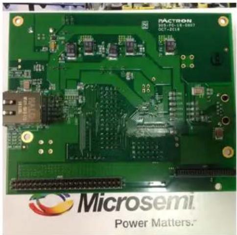
The evaluation board provides a way to evaluate the VSC8541 and VSC8531 devices in multiple configurations. Two RJ-45 connectors are provided for the copper media interface from each device. The MAC interface is exposed through 0.1 inch pin-headers, J206, J202, and J203. For standalone access to all device features, an external microcontroller is used to configure both the VSC8541 and the VSC8531 through the MDIO bus. The graphical user interface (GUI) enables the user to read and write device registers.
Figure 1 • VSC8541EV—Top View

natural_image
Green printed circuit board with various electronic components and connectors (no readable text or symbols)Figure 2 • VSC8541EV—Bottom View
natural_image
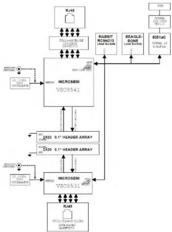
Green printed circuit board with various electronic components and connectors (no readable text or symbols)The following illustration shows a simplified block diagram of the VSC8541EV.
Figure 3 • VSC8541EV Simplified Block Diagram
flowchart
graph TD
A["RJ46"] --> B["BIU1-CCRTILF MICROSEMIA"]
B --> C["MICROSEMI VSC8541"]
C --> D["2X20 0.1" HEADER ARRAY"]
D --> E["MICROSEMI VSC8531"]
E --> F["RJ45"]
F --> G["BIU1-EIG41E-LICR<br>INTIGRADED<br>SIGNALS"]
C --> H["RABBIT RCM4210 (Just Socket)"]
C --> I["BEAGLE-BONE (Just Socket)"]
C --> J["8051uC CYONL &O<br>SIGNALS"]
C --> K["MSI"]
D --> L["2X20 0.1" HEADER ARRAY"]
E --> M["MSI"]
style A fill:#f9f,stroke:#333
style B fill:#ccf,stroke:#333
style C fill:#cfc,stroke:#333
style D fill:#fcc,stroke:#333
style E fill:#cff,stroke:#333
style F fill:#ffc,stroke:#333
style G fill:#fcc,stroke:#333
style H fill:#fff,stroke:#333
style I fill:#fff,stroke:#333
style J fill:#fff,stroke:#333
style K fill:#fff,stroke:#333
Other collateral for the VSC8541/VSC8531 devices and VSC8541EV—including schematics, layout, GUI, and application notes—can be downloaded from the Microsemi website.
3 Key Features
The following sections describe key features of the VSC8541EV.
3.1 Copper Port RJ45 Connections
The VSC8541 media dependent interface (MDI) uses generic RJ-45 connectors with an open-source, hardware-compliant HALO® Electronics Genesus™ TG111-MSC13LF 8-core discrete transformer. The VSC8531 MDI uses a HALO® Electronics integrated magnetics R-J45 connector, HFJ11-1G41E-L12RL.
3.2 MAC Interface Connector
The parallel MAC interface signals are available through 0.1 inch pin-headers.
3.2.1 RGMII Interface
RGMII signals from VSC8541 and VSC8531 are routed to J200 and J201, respectively. J200 and J201 are placed face-to-face in such a way that 0.1 inch shunt jumpers can be used to connect RXD and TXD between the two PHYs. This will allow traffic flow between the two PHYs so that Ethernet traffic tests (such as Iperf or Ping-Test) can be easily performed. The RXD and TXD within VSC8541 are routed to allow traffic to be looped back within a single PHY. The routing for VSC8531 is similar.
The following table shows the RGMII connector layout.
Table 1 • RGMII Connector Layout
| VSC8541 (J200) VSC8531 (J201) | ||
| GND TXD3 RXD3 GND | ||
| GND RXD3 TXD3 GND | ||
| GND TXD2 RXD2 GND | ||
| GND RXD2 TXD2 GND | ||
| GND GTX_CLK RX_CLK GND | ||
| GND RX_CLK_ext RX_CLK_ext GND | ||
| GND RX_CLK GTX_CLK GND | ||
| GND TXD1 RXD1 GND | ||
| GND RXD1 TXD1 GND | ||
| GND TXD0 RXD0 GND | ||
| GND RXD0 TXD0 GND | ||
| GND TX_CTL RX_DV | GND | |
| GND RX_DV | TX_CTL | GND |
3.2.2 RMII Interface
The RMII interface uses a subset of RGMII signals, and so RMII signals are available through 0.1 inch pinheaders on J200 and J201 for VSC8541 and VSC8531, respectively.
3.2.3 MII/GMII Interface (VSC8541 only)
The rest of the VSC8541's MAC interface signals for MII and/or GMII modes are routed to J202 and J203. The RXD signals are on J203 and TXD signals are on J202. They are also placed side-by-side to allow traffic to be looped back within the VSC8541.
3.3 Reference Clock
By default, both PHYs are configured for 25 MHz on-chip oscillator-enabled mode. The user may choose to provide an external reference clock through the SMA connector to J213 and J302 (as shown in ) for VSC8541 and VSC8531, respectively.VSC8541EV—Top View
The following steps are required to route the SMA signal to the device.
- Configure the REFCLK_SEL_0 and REFCLK_SEL_1 state according to the desired reference clock frequency. By default, there are pull-down resistors (R246 and R244 for VSC8541, and R319 and R320 for VSC8531) as needed for 25 MHz on-chip oscillator-enabled mode.
- Reorient the dual-position 0 Ω resistors R207 (for VSC8541) and R305 (for VSC8531), as shown from the PCB layout view in the following illustration.
Figure 4 • REFCLK Input Options—R207 and R305 Dual-Position Orientation

text_image
To J213 L201 L200 Y200 C221 R205 R204 R207 R246 R244 C228 ext R319 R320 R305 C32 R300 R301 R319 C319 X3 To J302Note: The external reference clock must be a 2.5 V LVTTL or similar type of signal because the REFCLK signal is referenced to VDD25A.
The reference clock selection for VSC8541 is independent of that for VSC8531.
Note: SMA connectors are not normally populated. If this is desired, please contact your local Microsemi representative and request this when placing the evaluation board order.
3.4 Recovered Clock and Clockout
The VSC8541 offers both a recovered clock output and a clockout signal that is available on the 0.1 inch pin-header J208. VSC8531 has a clockout signal available on the 0.1 inch pin-header J301. In the default configuration, CLK_SQUELCH_IN is left floating with an accessible test point on J207, which disables the clock squelching.
3.5 Bootstrapping Option
The reserved external pull-up resistors are located at the bottom side of the board. By default, VSC8541 and VSC8531 are bootstrapped to the following configuration.
- Unmanaged mode
• 10/100/1000 FDX/HDX
• ANEG enabled
• RGMII MAC with 2.0 ns internal delay setting
• PHY address of 0x0 (for VSC8531) and 0x1 (for VSC8541)
3.6 LEDs
LED0 from each PHY is connected to the LED on RJ-45 as well as discrete LEDs (LED1 for VSC8541 and LED2 for VSC8531). LED1 from each PHYs is connected to the other LED on the RJ-45.
3.7 MDINT, Fast Link Fail
MDINT from each PHY is available through a 0.1 inch pin-header on J206. Fastlink_Fail from VSC8541 is also connected to one of the pin-headers on J206.
3.8 Software Interface Microcontroller
A Silabs F340 microcontroller is included to facilitate a software interface to the registers on the VSC8541 and VSC8531 through the USB port.
Note: Alternatively, a Rabbit card is available for an IP-based manager of the PHY register space, to be installed onto the U402 connector of the board's bottom side. Another option is for MDC and MDIO to be accessed on pin-header, J206, if it is desired for another microcontroller to host the PHY register space.
3.9 Power Supply Options
There are three power supply options for the evaluation board, described in the following sections.
3.9.1 Single 5.0 V Input for DUT and Other Components
In this option, the VSC8541EV is powered by plugging in a USB cable to the board and to a PC. The board has three on-board switching regulators that will convert the 5.0 V supplied by the PC to 1.0 V and 2.5 V for the DUT (VSC8541 and VSC8531) and 3.3 V for the other components. The 1.0 V supply is used to power VDD1, and the 2.5 V supply is used to power VDD25A, VDDIO, VDDMAC, and VDDMDIO.
If desired, VDDIO, VDDMAC, and VDDMDIO can be individually supplied with external power supplies.
3.9.2 DUT Power Rails Isolated from non-DUT Power
This option allows for the multi-rails DUT power supplies—VDDIO, VDDMAC, and VDDMDIO—to be isolated from the rest of the board power, as follows:
- Remove the desired shunt jumper(s) between VDD25 and VDDIO on J211, VDD25 and VDDMAC on J212, and/or VDD25 and VDDMDIO on J204.
- Connect the proper supply to pin2 of J211, J212, or J204 for the desired VDDIO, VDDMAC, or VDDMDIO, respectively.
Note: This change will impact both VSC8541 and VSC8531
3.9.3 External 5.0 V DC Supply
Alternatively, the user can provide an external 5.0 V DC supply to the board instead of getting it from the USB. Remove the shunt jumpers between 5V0 and VBUS on J501, then provide the external 5.0 V DC supply to the 5V0 pin-headers.
4 Quick Start
This section describes how to install and run the GUI to fully control the evaluation board.
4.1 Connecting the Power Supply
The evaluation board is powered by the USB and the on-board switching regulators convert the 5.0 V USB power to the required supplies for the devices on the board. The user should immediately see LED3 illuminate (located by U501) when turned on, which confirms that the proper 5.0 V and 2.5 V are now available. This would indicate that the proper 1.0 V and 3.3 V are also up, assuming the switching regulators (U500 and U502) are working as expected.
4.2 Installing the PC Software
- Download the ZIP file from Microsemi's website onto a PC that has a USB port.
- Install the GUI by launching setup.exe or VSC8541EV_Install.msi.
- At the end of the GUI installation, the VSC8541EV GUI shortcut will be put onto the desktop.
- Double click the desktop icon to launch the GUI.
4.3 Connecting the Board to the PC
Launch the GUI by either clicking on the VSC8541EV desktop shortcut or clicking the VSC8541EV icon under Start-Programs. The initial window will detect the attached USB devices automatically.
The following illustration shows a typical GUI welcome window.
Figure 5 • GUI Welcome Window

text_image
Welcome to the VSC8531/41 Evaluation System COM Select: COM3 Scan COM Controller Present PHY(s) Connected Port(s) found 0 Try Connecting Launch CLI Launch GUIChoose the correct COM port from the drop-down menu and then click .Try Connecting
In a short moment, the Controller Present and PHY(s) Connected green LEDs will light up. Next, click and the VSC8531_VSC8541 Eval Board GUI window will appear. Launch GUI
Figure 6 • GUI Window

text_image
VISC51 Register List / VISC51 Summary MI 64 MI 62 MI 60 MI Port: 0 Register Description [FWQ] 15 Software Reset [FW] 14 Loopback [FW] 13 Faced Speed Selection LSB [FW] 12 AutoNavigation Enable [FW] 11 Power Down [FW] 10 Inade [FWQ] 9 Standard AutoNavigation [FW] 8 Distance Mode [PO] 7 Collision Test Enable [PO] 6 Forged Speed selection HBD [PO] 5/0 Renived Register Value Selected Req Page (Hex) 0000 Selected Req Address 0 Reset Value (Hex) 1040 Current Value (Hex) 1040 Port: 1 Register Description [FWQ] 15 Software Reset [FW] 14 Loopback [FW] 13 Faced Speed Selection LSB [FW] 12 AutoNavigation Enable [FW] 11 Power Down [FW] 10 Inade [FWQ] 9 Standard AutoNavigation [FW] 8 Distance Mode [PO] 7 Collision Test Enable [FO] 6 Forged Speed selection MSB [PO] 5/0 Renived Register Value Selected Req Page (Hex) 9000 Selected Req Address 8 Reset value (Hex) 1040 Current value (Hex) 1040 CONCITED:For ease of use, the GUI window displays two controllers—the left side (port 0) is for VSC8531 and the right side (port 1) is for VSC8541. The Port drop-down menu can also be used to select a different PHY (port) address.
Note: If port 1 is selected on both the left and the right controller, then both controllers will be accessing VSC8541 and the same register value will be seen on both sides.
Verify the devices are up and running by reading MII register 0—it should read back 0x1040. Reading back all 0s or all 1s indicates a problem. As indicated in the preceding figure, the extended MII register pages can be accessed to read or write by clicking on one of the ExtMII/Ext2MII/ExtGMII tabs.
VSC8531 Summary and VSC8541 Summary can be used as a register dump mechanism.
4.4 Board Initialization
VSC8541 and VSC8531 are configured on the evaluation board using the hardware strapping feature with the following initial settings.
• Unmanaged mode with auto-negotiation enabled and 10/100/1000 FDX/HDX advertised
• RGMII MAC mode with 2.0 ns internal delay setting
• The PHY addresses for VSC8541 and VSC8531 are 0x1 and 0x0, respectively
Once the evaluation board connectivity has been established and confirmed, the PHY should be initialized.
Note: A proper NRESET will be issued to both VSC8541 and VSC8531 by the Silabs F340 microcontroller during the board power-up process.
4.4.1 MAC Interface Reconfiguration
VSC8541 and VSC8531 are boot-strapped as RGMII mode. To reconfigure the MAC interface, set MII register 23 bit2 12:11 as follows:
• 00: GMII/MII (only valid for VSC8541)
01: RMII
10: RGMII
Note: After configuring bits 12:11 of MII register 23, a software reset (register 0.15) must be asserted to change the device operating mode.
Note: In order to perform Ethernet traffic testing in RMII mode, an actual MAC device (or similar) must be used or internal loopback (near-end loop) mode shall be used.
4.4.2 Copper Media Interface (Auto-negotiation Enabled)
The easiest configuration for passing traffic is with Auto-neg enabled (MII register 0, bit 12=1). Use MII registers 0, 4, and 9 to change the speed and restart auto-neg (register 0, bit 9) to advertise new settings.
As per the datasheet descriptions, the commonly-used speed advertisement definitions are listed in the following table.
Table 2 • Auto-negotiation Advertisements
| Mode MII reg 4 bits 8:7 MII reg 4 bits 6:5 MII reg 9 bits | 12:11 | MII reg 9bits 9:8 |
| 1000BT Master Mode N/A N/A 11 11 | ||
| 1000BT Slave Mode N/A N/A 10 11 | ||
| 100 BASE-TX Full Duplex 11 N/A N/A 00 | ||
| 10 BASE-T Full Duplex 00 11 N/A 00 |
The following steps should be followed to configure a link.
- Set up the copper traffic source (for instance, IXIA or Smartbits).
- Connect Ethernet cable(s) to a single or multiple RJ-45 port(s).
- Configure auto-negotiation as previously described and re-start ANEG (MII bit 0.12).
- The linkup bit is in MII register 1, bit 2. Read it twice to update.
Traffic should now be flowing, assuming the MAC interface is properly configured and connected as discussed in .MAC Interface Reconfiguration
4.5 Useful Test Features
VSC8541EV provides several useful test features, as described in the following sections
4.5.1 Ethernet Packet Generator
ExtMII 29 is the internal Ethernet Packet Generator (EPG) register. The EPG has the option to transmit traffic in multiples of 10,000 frames, regardless of when you stop transmit activity or transmit a burst of 30,000,000 packets. Refer to the datasheet for configuration options.
A Good CRC packet counter is in ExtMII 18.13:0. The Good CRC packet counter is a modulo 10,000 counter, so values will always be between 0 and 9,999. A read of the register reads-back the good CRC packets and then clears the register so the subsequent reads will be 0 if no traffic has been received. If traffic has been received since the last read, bit 15 will be set.
4.5.2 Copper PHY Error Counters
- Idle errors= MII 10.7:0
• RX errors= MII 19.7:0 - False carrier= MII 20.7:0
• Disconnects= MII 21.7:0
• CRC errors= ExtMII 23.7:0
4.5.3 Near-End Loopback
When the near-end loopback test feature is enabled, the transmitted data is looped back in the PCS block on the receive data signals. To enable the loopback, set MII register 0 bit 14 to 1. Near-end loopback requires proper configuration of J200 and/or J201.
4.5.4 Far-End Loopback
When the far-end loopback test feature is enabled, incoming data from a link partner on the copper interface is transmitted back to the link partner on the copper interface. To enable the loopback, set register bit 23.3 to 1.
4.5.5 Transmitter Test Mode
1000BASE-T PMA test control can be configured through MII register 9, bits 15:13. Refer to the PMA Test application note for additional information on performing the PMA conformance test.

Microsemi.
a MICROCHIP company
Microsemi Headquarters
One Enterprise, Aliso Viejo,
CA 92656 USA
Within the USA: +1 (800) 713-4113
Outside the USA: +1 (949) 380-6100
Sales: +1 (949) 380-6136
© 2017 Microsemi. All rights reserved. Microsemi and the Microsemi logo are trademarks of Microsemi Corporation. All other trademarks and service marks are the property of their respective owners.
Microsemi makes no warranty, representation, or guarantee regarding the information contained herein or the suitability of its products and services for any particular purpose, nor does Microsemi assume any liability whatsoever arising out of the application or use of any product or circuit. The products sold hereunder and any other products sold by Microsemi have been subject to limited testing and should not be used in conjunction with mission-critical equipment or applications. Any performance specifications are believed to be reliable but are not verified, and Buyer must conduct and complete all performance and other testing of the products, alone and together with, or installed in, any end products. Buyer shall not rely on any data and performance specifications or parameters provided by Microsemi. It is the Buyer's responsibility to independently determine suitability of any products and to test and verify the same. The information provided by Microsemi hereunder is provided "as is, where is" and with all faults, and the entire risk associated with such information is entirely with the Buyer. Microsemi does not grant, explicitly or implicitly, to any party any patent rights, licenses, or any other IP rights, whether with regard to such information itself or anything described by such information. Information provided in this document is proprietary to Microsemi, and Microsemi reserves the right to make any changes to the information in this document or to any products and services at any time without notice.
Microsemi, a wholly owned subsidiary of Microchip Technology Inc. (Nasdaq: MCHP), offers a comprehensive portfolio of semiconductor and system solutions for aerospace & defense, communications, data center and industrial markets. Products include high-performance and radiation-hardened analog mixed-signal integrated circuits, FPGAs, SoCs and ASICs; power management products; timing and synchronization devices and precise time solutions, setting the world's standard for time; voice processing devices; RF solutions; discrete components; enterprise storage and communication solutions; security technologies and scalable anti-tamper products; Ethernet solutions; Power-over-Ethernet ICs and midspans; as well as custom design capabilities and services. Microsemi is headquartered in Aliso Viejo, California, and has approximately 4,800 employees globally. Learn more at www.microsemi.com.
VPPD-04410