SolidRack 8U - NAS Rocstor - Free user manual and instructions
Find the device manual for free SolidRack 8U Rocstor in PDF.

User questions about SolidRack 8U Rocstor
0 question about this device. Answer the ones you know or ask your own.
Ask a new question about this device
Download the instructions for your NAS in PDF format for free! Find your manual SolidRack 8U - Rocstor and take your electronic device back in hand. On this page are published all the documents necessary for the use of your device. SolidRack 8U by Rocstor.
USER MANUAL SolidRack 8U Rocstor
SolidRack 8U/12U/22U Wall Mount Adjustable Rack Enclosure
2-Post Open Frame Rack

natural_image
Three technical line drawings of structural frame assemblies, showing different frame layouts (no text or symbols present)User Manual
Table of Contents
Page
Rocstor Legal Disclaimer 1
Important Safety Information - - - - - - - - - - - - - - 2
Safety Instructions - - - - - - - - - - - - - - - - - - 3
Introduction - - - - - - - - - - - - - - - - - - - 4
Component Identification - - - - - - - - - - - - - - 5
Hardware and Accessories - - - - - - - - - - - - - - 6
Assemble the Rack (22U) - - - - - - - - - - - - 7,8,9,10
Rocstor Legal Disclaimer
The information presented in this manual is not warranted by Rocstor to be totally authoritative, error free, or complete. This publication is not meant to be a substitute for a detailed operational and a site-specific development plan for the use of the product. Therefore, Rocstor assumes no liability for damages, violations of codes, improper installation, system failures, or any other problems that could arise based on the use of this Manual.
THE WARRANTY AND REMEDIES SET FORTH ABOVE ARE LIMITED IN TIME TO THE DURATION OF THE WARRANTY AS STATED HEREIN AND IS EXCLUSIVE IN LIEU OF ALL OTHER WARRANTIES, LEGAL THEORIES, REMEDIES AND CONDITIONS, WHETHER ORAL OR WRITTEN, EXPRESS OR IMPLIED. IN NO EVENT SHALL ROCSTOR, OR ANY PARENT, AFFILIATE OR SUBSIDIARY COMPANY OF ROCSTOR OR THEIR RESPECTIVE OFFICERS, DIRECTORS, OR EMPLOYEES BE LIABLE FOR ANY DIRECT, INDIRECT, CONSEQUENTIAL, PUNITIVE, SPECIAL, OR INCIDENTAL DAMAGES, INCLUDING, WITHOUT LIMITATION, DAMAGES FOR LOSS OF BUSINESS, CONTRACTS, REVENUE, LOST PROFITS, DATA, INFORMATION, GOODWILL OR BUSINESS INTERRUPTION RESULTING FROM OR ARISING OUT OF THE USE OF THE PRODUCT OR FAILURE TO FOLLOW INSTRUCTIONS IN THE MANUAL.
FURTHERMORE, ROCSTOR SPECIFICALLY DISCLAIMS ANY AND ALL IMPLIED WARRANTIES INCLUDING, WITHOUT LIMITATION, WARRANTIES OF MERCHANTABILITY AND FITNESS FOR A PARTICULAR PURPOSE. IF ROCSTOR CANNOT LAWFULLY DISCLAIM SUCH IMPLIED WARRANTIES, THOSE IMPLIED WARRANTIES WILL BE LIMITED IN DURATION TO THE DURATION SET FORTH ABOVE.
FURTHER STILL, ROCSTOR RESERVES THE RIGHT TO MAKE CHANGES OR UPDATES WITH RESPECT TO THE CONTENT OF THE PUBLICATION OR THE FORMAT THEREOF AT ANY TIME AFTER PURCHASE WITHOUT NOTICE.
Some states and provinces do not allow the exclusion or limitation of incidental or consequential damages or exclusions or limitations on the duration of implied warranties or conditions, so the above limitations or exclusions may not apply to you. This warranty gives you specific legal rights and you may also have other rights that vary by state or province.
Copyright, intellectual, and all other proprietary rights in the content of the manual (including but not limited to software, audio, video, text, and photographs) rests with Rocstor or its licensor. All rights in the content are the property of Rocstor and are not granted, licensed, assigned or otherwise passed to the purchaser' of the product or to persons having access to the information in the manual
PHILLIPS ^® is a registered trademark of Phillips Screw Company in the United States or other countries.
Important Safety Information
Please review and read the instructions very carefully in order to understand the specification of the equipment. This is essential information before installing, operating, service or maintaining your equipment. These messages or alerts may appear throughout this publication and manual for your purchased equipment. The messages are designed to warn you of possible hazards or to bring to your attention the information that would assist and clarifies steps and procedures.

This symbol and label provides Danger or Warning safety which indicates an electrical hazard exists. If instructions are not fully followed, it may result in personal injury.

This is a safety alert symbol. It is used to alert you to potential personal injury hazards. Please follow the instructions very carefully and obey all safety messages that follow this symbol to avoid possible injury or death.
DANGER
DANGER This symbol represents an imminently hazardous situation which, if not avoided, will result in death or serious injury. Please follow instructions carefully.
WARNING
WARNING This symbol represents a potentially hazardous situation which, if not avoided, can result in death or serious injury. Please follow instructions carefully.
CAUTION
CAUTION This symbol indicates a potentially hazardous situation which, if not avoided, can result in minor or moderate injury.
CAUTION
CAUTION, This symbol is used without the safety alert symbol, indicates a potentially hazardous situation which, if not avoided, can result in equipment damage. Please follow instructions carefully. Please follow instructions carefully.
NOTICE
NOTICE This symbol provides informations and practices not related to physical injury including certain environmental hazards, potential damage or loss of data. Please follow instructions carefully.
Safety Instructions
Please follow the essential and important instructions in this manual. The information provides you useful instructions for installation and customization of the rack or equipment.
WARNING
TIP/HEAVY EQUIPMENT HAZARD
- The content of this packaging is easily tipped. Please be extra careful and use extreme caution when moving or unpacking this cabinet.
- Two people are preferred and are required to move, unpack and install the cabinet.
- Not following these instructions carefully, can result in death, serious injury, or equipment damage. Please follow the assembly instructions very carefully.
- This cabinet enclosure has 150 lb (68 kgs) Maximum Load Capacity. Please do not exceed the weight capacity limit of this product. Overloading the capacity of this product may result in bodily and property damage.
- This product is designed for indoor use. Do not use outdoors or in an open area. • DO NOT push the rack from its sides.
- This enclosure is not designed to be stacked. Do not place any items or liquids on top or around the enclosure.
- It is important to survey the area that this rack will be installed to assure the area is able to handle the total weight of the cabinet and the equipment inside the rack after all equipment installation.
Warning:
Do not attempt to mount to wall, when equipment is mounted inside rack.
Rack can hold up to 150 pounds evenly distributed. Make sure wall surface can hold weight of rack/equipment.
Not following these instructions carefully, it can result in death, serious injury, or equipment damage
Introduction
SolidRack 8U/12U/22U Wall Mount Adjustable Rack Enclosure - 2-Post Open Frame Rack - Low-Profile Switch-Depth Heavy Duty Rack - 150 lb (68 kgs) Maximum Load Capacity - 19" Rack Compatible - Cold-rolled Steel CRS - Flat-Pack, Assembly Required - EIA-310-E Standard - Black
Component Identification
Parts List
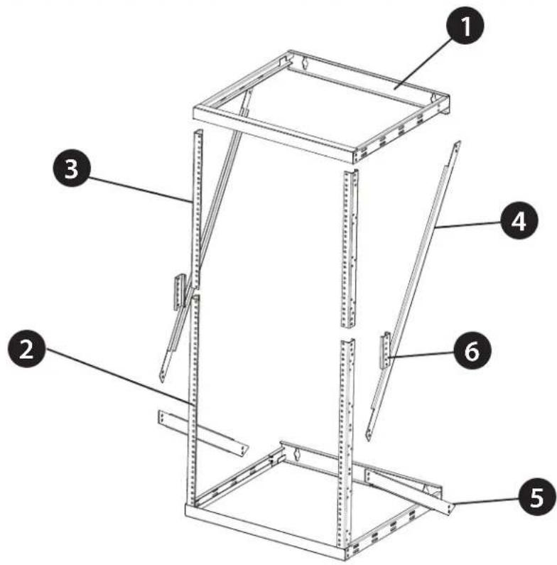
text_image
Technical diagram of a metal-framed storage unit with numbered components labeled 1 through 6
natural_image
Line drawing of a rectangular metal frame with internal slots and mounting holes (no text or symbols)Top/Bottom Panel Frame

1
Long Vertical Mounting Rail

2

Short Vertical Mounting Rail

natural_image
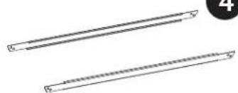
Two parallel cylindrical objects with textured surfaces, no text or symbols visibleLeft/Right Long Support Beam

4
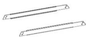
Left/Right Short Support Beam


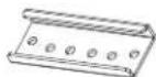
Mounting Rail Tie Plates

Hardware and Accessories
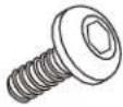 M5 x10mm Screwsx36 M5 x10mm Screwsx36 | 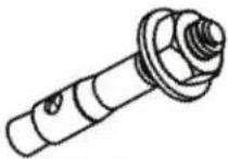 Anchorsx4 Anchorsx4 |  12-24 Mounting Screwsx24 12-24 Mounting Screwsx24 |
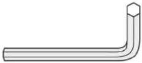 Hex Wrenchx1 Hex Wrenchx1 |  Zip Ties Zip Ties |
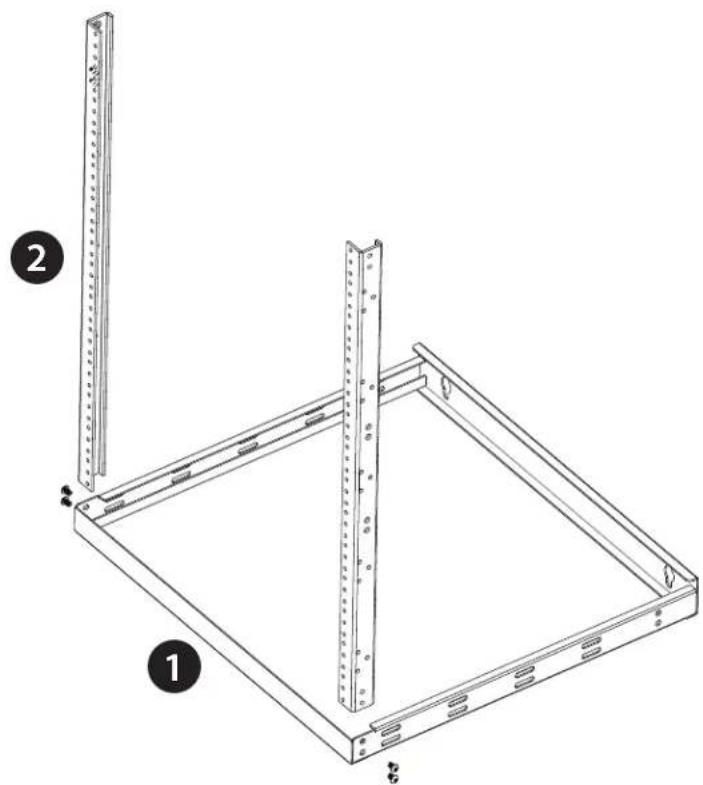
Assemble the Rack (22U Configuration)
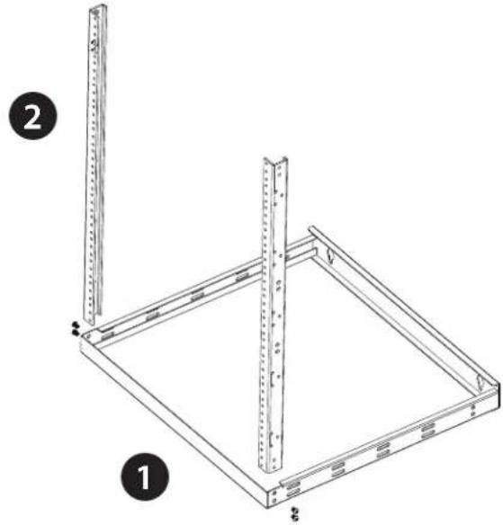
- Insert one end of the Long Vertical Mounting Rails (2) into the corner of the Bottom Panel Frame (1) (both panel frames can be used as a top or a bottom) and secure them with 2 of the M5 x 10 mm Hex Head Screws on each side using Hex Wrench. Note: The front of the Bottom Mounting Panel Frame (1) has a front panel without wall mounting holes.
natural_image
Technical line drawing of a metal frame structure with two vertical supports and mounting holes (no text or symbols)Assemble the Rack (22U Configuration)
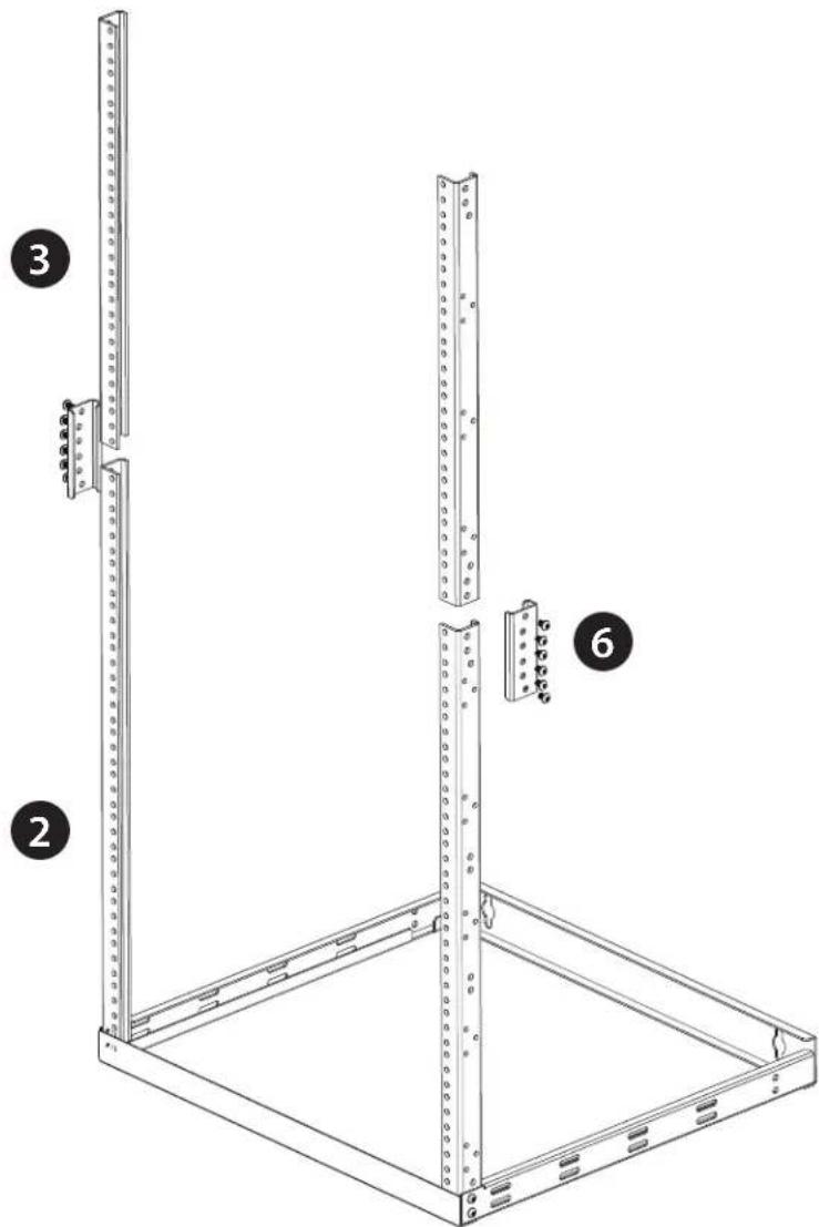
- Using one of the Mounting Rail Tie Plates (6) and six of the M5 x 10 mm Hex Head Screws, connect one set of the Short Vertical Mounting Rails (3) to the Long Vertical Mounting Rails (2) using Hex Wrench. Repeat this step for the other set of vertical rails.
text_image
Technical diagram of a rack-mounted server unit with labeled components and mounting pointsAssemble the Rack (22U Configuration)
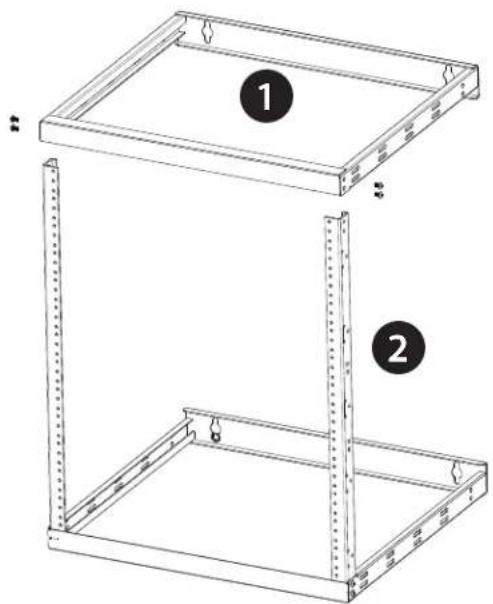
- Insert and connect the Top Panel Frame (1) onto the combined vertical mounting rails with 2 of the M5 x 10 mm Hex Head Screws on each side using Hex Wrench.

natural_image
Technical line drawing of a server rack unit with mounting holes and structural ribs (no text or symbols)Assemble the Rack (22U Configuration)
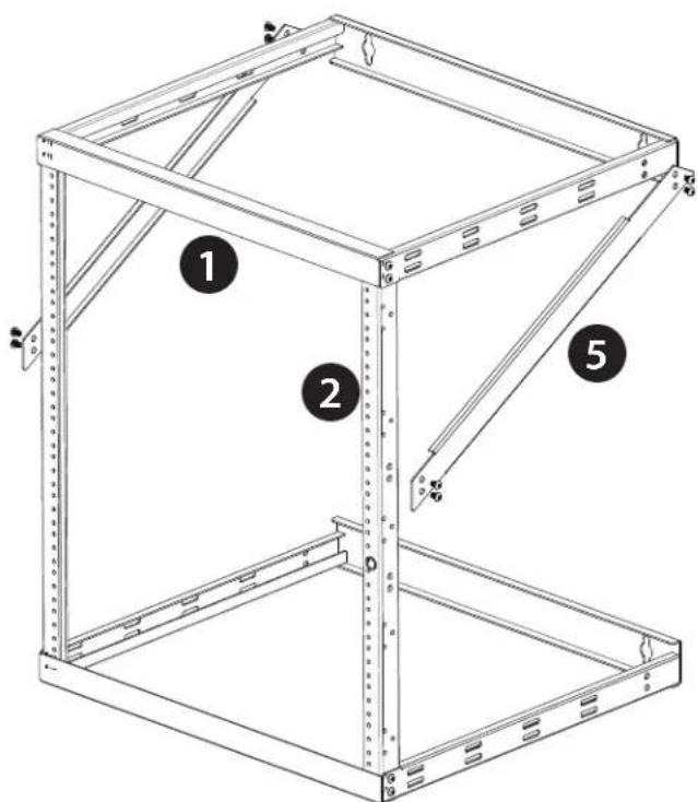
- Attach Right and Left Long Support Beams (4) to the frame by securing 8 of the M5 x 10 mm Hex Head Screws to the sides of the Top Panel Frame (5) and Vertical Mounting Rails using Hex Wrench. Attach the Right and Left Short Support Beams (5) to the frame by securing 8 of the M5 x 10 mm Hex Head Screws to Vertical Mounting Rails and to the Bottom Panel Frame (1) using Hex Wrench.

text_image
Technical diagram of a metal frame structure with numbered components and close-up insets showing assembly details.Assemble the Rack (12U Configuration)
- Insert one end of the Long Vertical Mounting Rails (2) into the corner of the Bottom Panel Frame (1) (both panel frames can be used as a top or a bottom) and secure them with 2 of the M5 x 10 mm Hex Head Screws on each side using Hex Wrench.
Note: The front of the Bottom Mounting Panel Frame (A) has a front panel without wall-mounting holes.
natural_image
Technical line drawing of a metal frame structure with two vertical supports and a base plate (no text or symbols)- Insert and connect the Top Panel Frame (1) onto the Long Vertical Mounting Rails (2) with 2 of the M5 x 10 mm Hex Head Screws on each side using Hex Wrench.
natural_image
Technical line drawing of a two-tier metal enclosure with mounting holes and structural supports (no text or symbols)Assemble the Rack (12U Configuration)
- Attach the Right and Left Short Support Beams (5) to the frame by securing 8 of the M5 x 10 mm Hex Head Screws to Long Vertical Mounting Rails (2) and to the Bottom Panel Frame (1) using Hex Wrench.
text_image
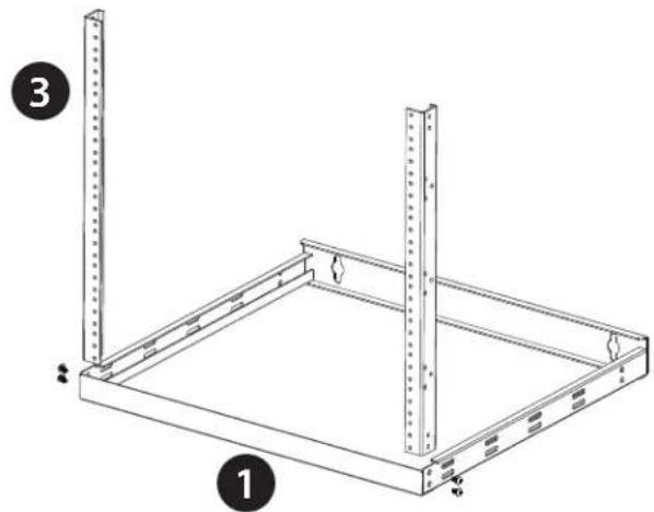
Technical diagram of a metal frame structure with numbered components labeled 1, 2, and 5.Assemble the Rack (8U Configuration)
- Insert one end of the Short Vertical Mounting Rails (3) into the corner of the Bottom Panel Frame (1) (both panel frames can be used as a top or a bottom) and secure them with 2 of the M5 x 10 mm Hex Head Screws) on each side using Hex Wrench.
Note: The front of the Bottom Mounting Panel Frame (1) has a front panel without wall-mounting holes.
natural_image
Technical line drawing of a metal shelving unit with two vertical posts and mounting holes (no text or symbols)- Insert and connect the Top Panel Frame (1) onto the Long Vertical Mounting Rails (2) with 2 of the M5 x 10 mm Hex Head Screws on each side using Hex Wrench.

natural_image
Technical line drawing of a two-tier metal shelving unit with mounting holes and structural ribs (no text or symbols)Enclosure Installation
CAUTION
CAUTION, This symbol is used without the safety alert symbol, indicates a potentially hazardous situation which, if not avoided, can result in equipment damage. Please follow instructions carefully. Please follow instructions carefully.
NOTICE
NOTICE This symbol provides informations and practices not related to physical injury including certain environmental hazards, potential damage or loss of data. Please follow instructions carefully.
Tools Requirement & Preparation for Installation
Make sure you inspect the area that this racks will be installed. This enclosure should be installed in a structurally sound area that can handle the load and the weight of the racks. If you place the enclosure on a level floor, make sure the floor can bear the weight of the enclosure, all equipment that will be installed in the enclosure. For permanent wall mount installation, make sure to securely fasten the enclosure to the building structure.
The following tools are required for proper installation:
- Level (not included)
• Phillips-head screwdriver (not included) - Appropriate tools for wall mounting (not included)
- Appropriate hardware for wall mounting (not included)
Five-Year Factory Warranty
Rocstor provides a Limited Factory Warranty which applies to products you have purchased for commercial or industrial use in the ordinary course of your business.
Terms of warranty
Rocstor warrants its SolidRack product series to be free from defects in materials and workmanship for a period of five years from the date of purchase. Rocstor's obligation under this warranty coverage is limited to repairing or replacing, at its sole discretion, any such defective products. This warranty does not apply to equipment that has been damaged by accident, negligence, or misapplication or has been altered or modified in any way. In the event Rocstor repairs or provide a replacement of a defective product or part, the warranty does not extend the original warranty period. Rocstor reserves the right to repair or replace any parts under warranty as new or factory re manufactured.
Non-transferable warranty
This warranty extends only to the original purchaser who must have properly registered the product. The product may be registered at the Rocstor Web site, https://rocstor.com/customer-support/warranty registration.
Exclusions
If Rocstor tests or examines the alleged defect in the product and finds that the damages or defects do not exist or were caused by a third party or an end user's misuse, improper installation or testing, or negligence, then Rocstor shall not be liable under the warranty. Furthermore, unauthorized attempts to repair or modify the product by wrong or inadequate electrical connection or voltage, inadequate or inappropriate site operation conditions, repair, installation corrosive area or atmosphere, a change in location or operating conditions or use, repair by non-Rocstor designated personnel, exposure to the elements, fire, Acts of God, theft, or equipment installation not recommended or contrary to Rocstor's specifications or recommendations. Warranties will be void and Rocstor will not be liable if the product serial number is tampered with, altered, removed, defaced or any other cause beyond the range of intended use.
Contact Information
Corporate Headquarters
12979 Arroyo Ave
San Fernando, CA 91340 - USA
Office: +1 (818) 727-7000
Email: info@Rocstor.com
Technical Support / RMA
Hours: 9:00 am - 5:00 pm PST
Mon - Fri (excluding holidays)
Tell: +1 (818) 727-7000 (Domestic and Internationals)
Email: support@Rocstor.com
Sales Info
Hours: 8:00 am - 5:00 pm PST
Mon - Fri (excluding holidays)
Tell: +1 (818) 727-7000 (Domestic and Internationals)
Email: support@Rocstor.com
Corporate, Government and Academic Customers
Our Corporate Sales Team's goal is to help our U.S.A. and Canadian customers find a storage solution that best serves their needs. We will help you determine your best purchasing options. For more information please contact the appropriate department below or call us at +1 (818) 727-7000.
General sales information: sales@Rocstor.com
Corporate sales information: corporate_sales@Rocstor.com
Educational sales information: academic_sales@Rocstor.com
Federal, State & Local government sales information: government_sales@Rocstor.com
Resellers/Business Development/OEM Partners
All Channel National and International Resellers, VARs, Consultants ...
contact Rocstor Channel Sales: call: +1 (818) 727-7000
Email: reseller_info@Rocstor.com