HY-SPKP-600W50A - Solar charge controller ACOPower - Free user manual and instructions
Find the device manual for free HY-SPKP-600W50A ACOPower in PDF.

User questions about HY-SPKP-600W50A ACOPower
0 question about this device. Answer the ones you know or ask your own.
Ask a new question about this device
Download the instructions for your Solar charge controller in PDF format for free! Find your manual HY-SPKP-600W50A - ACOPower and take your electronic device back in hand. On this page are published all the documents necessary for the use of your device. HY-SPKP-600W50A by ACOPower.
USER MANUAL HY-SPKP-600W50A ACOPower
—MPPT Solar Charge Controller
User Manual

text_image
MPPT SOLAR CHARGE CONTROLLERImportant Safety Instructions
Please reserve this manual for future review. This manual contains all instructions of safety, installation and operation of Tracer AN series controller ("the controller" is referred in this manual).
General Safety Information
Read all the instructions and warnings carefully before installation.
➢ No user serviceable component inside controller. DO NOT disassemble or attempt to repair the controller.
- Avoid direct sunlight, high temperatures and DO NOT install the controller at locations where water can get in.
Install the controller at well ventilated places, the controller's heat sink will be very hot during operation.
- Installing appropriate external fuses/breakers is suggested.
➢ Please make sure to switch off all connections of the PV array and the fuse/breakers which close to the battery before the controller installation and adjustment.
➢ Power connections must remain tight to avoid excessive heating from the loose connection.
Contents
1 General Information....1
1.1 Overview .... 1
1.2 Characteristics....2
1.3 Designations of Controller Models....3
1.4 Accessories (Included)....3
1.5 Accessories (optional)......4
2 Installation ....5
2.1 General Installation Notes....5
2.2 PV Array Requirements....5
2.3 Wire Size....8
2.4 Relay instruction....9
2.5 Mounting ....11
3 Operation....16
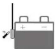
3.1 Indicator ....16
3.2 Button....16
3.3 LCD Display ....17
3.4 Setting....18
4 Protections, Troubleshooting & Maintenance....20
4.1 Protections ...... 20
4.2 Troubleshooting....21
4.3 Maintenance....22
5 Specifications ....23
Annex I Dimensions....25
1 General Information
1.1 Overview
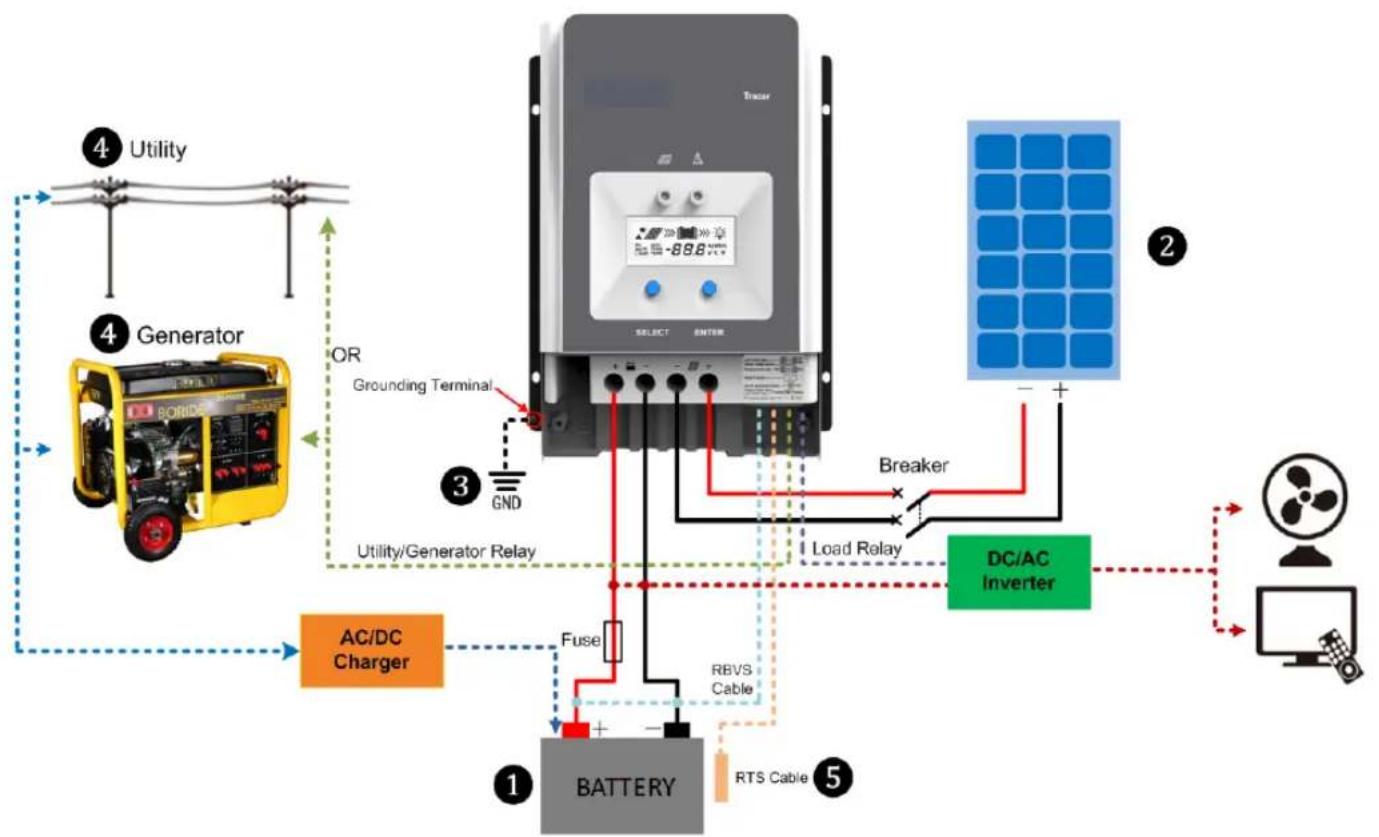
Tracer AN series controller, based on multiphase synchronous rectification technology (MSRT) and advanced MPPT control algorithm, with dual-core processor architecture and common negative design, has the features of high response speed, high reliability, and high industrial standard. MSRT can guarantee very high conversion efficiency in any charge power, which sharply improves the energy efficiency of solar system; Advanced MPPT control algorithm minimize the maximum power point loss rate and loss time, to ensure the tracking efficiency, corresponding speed as well as high conversion efficiency under high or low power, so that in any situation, Tracer AN products can rapidly track the maximum power point(MPP) of PV array to obtain the maximum energy of the panel. The limitation function of the charging power and current, and automatic power reduction function fully ensure the stability when works with oversize PV modules and operate under high temperature environment.
With the adaptive three-stage charging mode based on digital control circuit, Tracer AN series controllers can effectively prolong the life-cycle of battery and significantly improve the system performance. The load, utility or generator auto-control relays make it easy to compose the hybrid power system. All-around electronic protections, including overcharging, over discharging, and PV reverse polarity protection, effectively ensure the safer and more reliable operation of the solar system for a longer service time. The isolated RS485 interface with standard MODBUS communication protocol and 5V power supply makes it easy for customer to expand the application, it support up to 8 charging in parallel to expand system and meet with different monitoring requirements, so that can be widely used for various applications, e.g. solar RV, household system and field monitoring, etc.
Features:
- CE certification(LVD EN/IEC62109, EMC EN61000-6-1/3)
- High quality & low failure rate components of ST and Infineon to ensure the product's life
- Advanced MPPT technology & ultra-fast tracking speed, with tracking efficiency no less than 99.5%
• Maximum DC/DC transfer efficiency is as high as 98.6% ^ , full load efficiency is up to 98% ^ - Advanced MPPT control algorithm will minimize the MPP loss rate and loss time
- The accuracy of the recognition and tracking at the highest point of multiple-peaks MPP
- The wider range of MPP operating voltage.
- Auto control system to limit the charging power & current go over the rated value.
- Support 4 charging options: Sealed, Gel, Flooded and User.
- Battery temperature compensation function
• Real-time energy recording and statistical function
• Automatic over-temperature power reduction function - Hundred percent full load operation in working environment temperature range within charging & discharging
• Support up to 8 units in parallel to expand system - Load relay control external load switch signal to realize diversified load work modes
- The first and the second disconnection of load control, contain two relay's contact.
• Auto-control of utility and generator relay design
- Utility or generator auto-control relays make it easy to compose the hybrid power system
- The remote temperature and the voltage sensor design will collect accurate data of battery temperature and voltage
- Isolated RS485 with 5VDC/200mA to protect output for no power devices with MODBUS protocol
- To monitor or set the parameters by using the phone Apps or PC software.
★Tracer10415AN@48V system
1.2 Characteristics

text_image
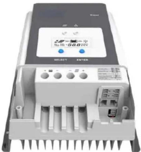
1 2 3 4 5 MPPT SOLAR CHARGE CONTROLLER SELECT ENTER 18 17 16 15 14 13 12 11 10 9 8 7 6 5| 1-Charging LED indicator | 10- Utility/Generator relay ON |
| 2-SELECT button | 11-RBVS Port(4) |
| 3-Fuse | 12-Load control relay(5) |
| 4-Grounding Terminal | 13- Utility/Generator relay OFF |
| 5-Cover screw holes M4 | 14-PV Terminals(6) |
| 6-PV reverse polarity alarm indicator | 15-Battery Terminals(6) |
| 7- Generator and load relay enable(1) | 16-ENTER button |
| 8- RTS Port(2) | 17-LCD |
| 9- RS485 port(5VDC/200mA)(3) | 18-Fault LED indicator |
(1) Enabled Disabled Generator and load relay enabled when the switch is ON; Generator and load relay is disabled when the switch is OFF.
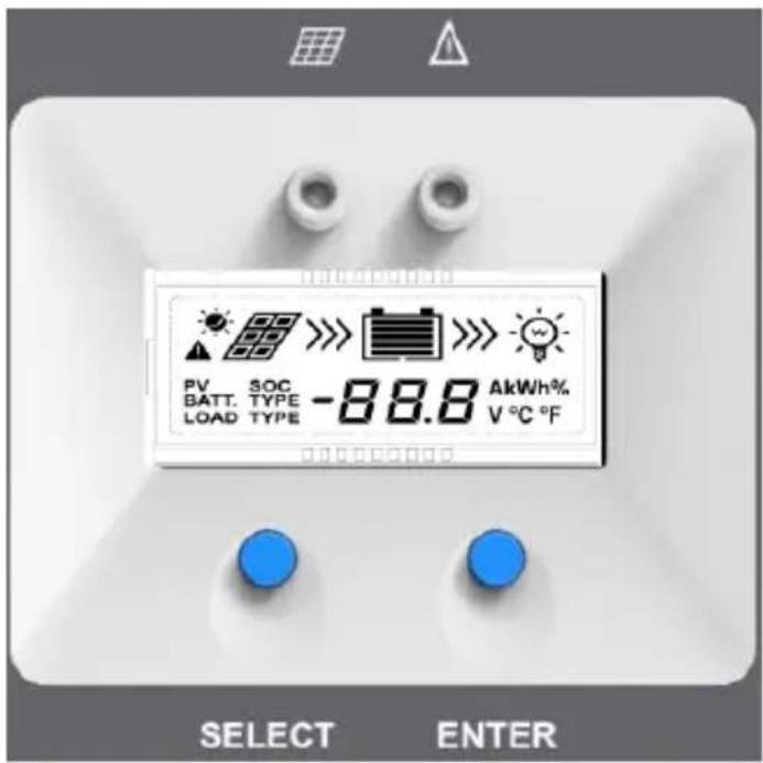
(2) Connect for a RTS (Remote Temperature Sensor) to remotely detect battery temperature, sample distance less than 20m.

CAUTION: If the temperature sensor is short-circuited or damaged, the controller charge or discharge at the default temperature setting of 25^ .
(3) When connect the controller to external devices, only one of the ports can be used; when use multiple controllers in parallel, the port are for cascaded use.

text_image
2*RJ45 GND A B 5VDC 1/2—GND 3/4—A 5/6—B 7/8--5VDC(4) Connect for RBVS (Remote Battery Voltage Sensor) to detect accurate battery voltage, sample distance less than 20m.
(5) Low Voltage Disconnect Voltage( V_LVD ) make the relay turn off; Low Voltage Reconnect Voltage( V_LVR ) make the relay turn on.
(6) Common negative design, with the same terminal of the PV and battery.
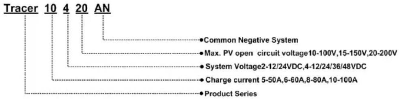
1.3 Designations of Controller Models
text_image
Tracer 10 4 20 AN • Common Negative System • Max. PV open circuit voltage10-100V,15-150V,20-200V • System Voltage2-12/24VDC,4-12/24/36/48VDC • Charge current 5-50A,6-60A,8-80A,10-100A • Product Series1.4 Accessories (Included)
| Item | Accessory Model Number Picture | |||
| 1 | Local Temperature Sensor | RT-MF58R47K3.81A(2P-3.81mm) | 1Pcs |  |
| 2 | Battery Voltage Sensor Terminal | 2P-3.81mm | 1Pcs |  |
| 3 | Load control delay Terminal | 2P-3.81mm | 1Pcs | |
| 4 | Diesel generator relay Terminal | 2P-3.5mm | 2Pcs |  |

WARNING: The Battery Voltage Sensor Terminal and Load Control Delay Terminal should not mix, otherwise the controller may be damaged.
1.5 Accessories (optional)
| Remote Temperature Sensor(RTS300R47K3.81A) |  | Acquisition of battery temperature for undertaking temperature compensation of control parameters, the standard length of the cable is 3m (length can be customized).The RTS300R47K3.81A connects to the port 8 on the controller.NOTE: The temperature sensor short-circuited or damaged, the controller will be charged or discharged at the default temperature 25 °C. |
| USB to RS485 cableCC-USB-RS485-150U |  | USB to RS485 converter is used to monitor each controller using Solar Station PC software. The length of cable is 1.5m. TheCC-USB-RS485-150U connects to the RS485 Port on the controller. |
| Remote MeterMT50 |  | MT50 can display various operating data and fault info the system. The information can be displayed on a backlit LCD screen, the buttons are easy-to-operate, and the numeric display is readable. |
| WIFI Serial AdaptereBox-WIFI-01 |  | After the controller is connected with the eBox-WIFI-01 through the standard Ethernet cable (parallel cable), the operating status and related parameters of the controller can be monitored by the mobile APP software through WIFI signals. |
| RS485 to Bluetooth AdaptereBox-BLE-01 |  | After the controller is connected with the eBox-BLE-01 through the standard Ethernet cable (parallel cable), the operating status and related parameters of the controller can be monitored by the mobile APP software through Bluetooth signals. |
| LoggereLOG01 |  | After the controller is connected with the eLOG-01 through the RS485 communication cable, it can record the operating data of the controller or monitor the real-time operating status of the controller via PC software. |
| PT AdapterPT-ADP | Manage to work and communicate with the 2 to 8 pcs controllers in parallel | |
| NOTE:1 For setting and operation of accessory, please refer to accessory's user manual.2When connect the controller to above accessories, only one of the ports can be used. | ||
2 Installation
2.1 General Installation Notes
- Before installation, please read through the entire installation instructions to get familiar with the installation steps.
- Be very careful when installing the batteries, especially flooded lead-acid battery. Please wear eye protection, and have fresh water available to wash and clean if any contact with battery acid.
- Keep the battery away from any metal objects, which may cause short circuit of the battery.
- Explosive battery gases may come out from the battery during charging, so make sure ventilation condition is good.
- Lead-acid battery are recommended, other kinds please refer to the battery manufacturer.
- Ventilation is highly recommended if mounted in an enclosure. Never install the controller in a sealed enclosure with flooded batteries! Battery fumes from vented batteries will corrode and destroy the controller circuits.
- Loose power connections and corroded wires may result in high heat that can melt wire insulation, burning surrounding materials, or even causing fire. Ensure tight connections and use cable clamps to secure cables and prevent them from swaying in mobile applications.
- Battery connection may be wired to one battery or a bank of batteries. The following instructions refer to a singular battery, but it is implied that the battery connection can be made to either one battery or a group of batteries in a battery bank.
- Multiple same models of controllers can be installed in parallel on the same battery bank to achieve higher charging current. Each controller must have its own solar module(s).
- Select the system cables according to 5A/mm ^2 or less current density in accordance with Article 690 of the National Electrical Code, NFPA 70.
2.2 PV Array Requirements
(1) Serial connection (string) of PV modules
As the core component of PV system, Controller could be suitable for various types of PV modules and maximize converting solar energy into electrical energy. According to the open circuit voltage ( V_oc ) and the maximum power point voltage ( V_mpp ) of the MPPT controller, the series number of different types PV modules can be calculated. The below table is for reference only.
Tracer6210AN:
| System voltage | 36cellVoc<23V | 48cellVoc<31V | 54cellVoc<34V | 60cellVoc<38V | ||||
| MAX. | Best | MAX. | Best | MAX. | Best | MAX. | Best | |
| 12V | 4 | 2 | 2 | 1 | 2 | 1 | 2 | 1 |
| 24V | 4 | 3 | 2 | 2 | 2 | 2 | 2 | 2 |
| System voltage | 72cell Voc<46V | 96cell Voc<62V | Thin-Film Module Voc>80V | ||
| MAX. Best MAX. Best | |||||
| 12V | 2 | 1 | 1 | 1 | 1 |
| 24V | 2 | 1 | 1 | 1 | 1 |
NOTE: The above parameter values are calculated under standard test conditions (STC (Standard Test Condition): Irradiance 1000W/m^2 , Module Temperature 25^ , Air Mass 1.5.)
Tracer5415/6415/8415/10415AN:
| System voltage | 36cellVoc<23V | 48cellVoc<31V | 54cellVoc<34V | 60cellVoc<38V | ||||
| MAX. | Best | MAX. | Best | MAX. | Best | MAX. | Best | |
| 12V | 4 | 2 | 2 | 1 | 2 | 1 | 2 | 1 |
| 24V | 6 | 3 | 4 | 2 | 4 | 2 | 3 | 2 |
| 48V | 6 | 5 | 4 | 3 | 4 | 3 | 3 | 3 |
| System voltage | 72cell Voc<46V | 96cell Voc<62V | Thin-Film Module Voc>80V | ||
| MAX. Best MAX. Best | |||||
| 12V | 2 | 1 | 1 | 1 | 1 |
| 24V | 3 | 2 | 2 | 1 | 1 |
| 48V | 3 | 2 | 2 | 2 | 1 |
NOTE: The above parameter values are calculated under standard test conditions (STC (Standard Test Condition): Irradiance 1000W/m², Module Temperature 25°C, Air Mass 1.5.)
Tracer5420/6420/8420/10420AN:
| System voltage | 36cellVoc<23V | 48cellVoc<31V | 54cellVoc<34V | 60cellVoc<38V | ||||
| MAX. | Best | MAX. | Best | MAX. | Best | MAX. | Best | |
| 12V | 4 | 2 | 3 | 1 | 2 | 1 | 2 | 1 |
| 24V | 6 | 3 | 4 | 2 | 4 | 2 | 3 | 2 |
| 48V | 8 | 5 | 5 | 4 | 5 | 3 | 4 | 3 |
| System voltage | 72cell Voc<46V | 96cell Voc<62V | Thin-Film Module Voc>80V | ||
| MAX. Best | MAX. Best | ||||
| 12V | 2 | 1 | 1 | 1 | 1 |
| 24V | 3 | 2 | 2 | 1 | 1 |
| 48V | 4 | 3 | 2 | 2 | 2 |
NOTE: The above parameter values are calculated under standard test conditions (STC (Standard Test Condition): Irradiance 1000W/m², Module Temperature 25°C, Air Mass1.5.)
(2) PV array maximum power
The MPPT controller has the function of current/power-limiting, that is, during the charging process, when the charging current or power exceeds the rated charging current or power, the controller will automatically limit the charging current or power to the rated charging current or power, which can effectively protect the charging parts of controller, and prevent damages to the controller due to the connection of some over-specification PV modules. The actual
operation of PV array is as follows:
Condition 1:
Actual charging power of PV array ≤ Rated charging power of controller
Condition 2:
Actual charging current of PV array ≤ Rated charging current of controller
When the controller operates under "Condition 1" or "Condition 2", it will carry out the charging as per the actual current or power; at this time, the controller can work at the maximum power point of PV array.

WARNING: When the power of PV module is greater than the rated charging power, and the maximum open-circuit voltage of PV array is more than 100V(Tracer**10AN)/150V(Tracer**15AN)/200V(Tracer**20N) (at the lowest environmental temperature), the controller may be damaged.
Condition 3:
Actual charging power of PV array>Rated charging power of controller
Condition 4:
Actual charging current of PV array>Rated charging current of controller
When the controller operates under "Condition 3" or "Condition 4", it will carry out the charging as per the rated current or power.

WARNING: When the power of PV module is greater than the rated charging power, and the maximum open-circuit voltage of PV array is more than 100V(Tracer**10AN)/150V(Tracer**15AN)/200V(Tracer**20N) (at the lowest environmental temperature), the controller may be damaged.
According to “Peak Sun Hours diagram”, if the power of PV array exceeds the rated charging power of controller, then the charging time as per the rated power will be prolonged, so that more energy can be obtained for charging the battery. However, in the practical application, the maximum power of PV array shall not be greater than 1.5 x the rated charging power of controller. If the maximum power of PV array exceeds the rated charging power of controller too much, it will not only cause the waste of PV modules, but also increase the open-circuit voltage of PV array due to the influence of environmental temperature, which may increase the probability of damage to the controller rise. Therefore, it is very important to configure the system reasonably. For the recommended maximum power of PV array for this controller, please refer to the table below:
| Item | Rated Charge Current | Rated Charge Power | Max. PV Power | Max. PV Open Circuit |
| Tracer6210AN | 60A | 750W/12V1500W/24V | 1125W/12V2250W/24V | 100V ^® 92V ^® |
| Tracer5415AN | 50A | 625W/12V1250W/24V1875W/36V2500W/48V | 937.5W/12V1875W/24V2812.5W/36V3750W/48V | 150V ^® 138V ^® |
| Tracer6415AN | 60A | 750W/12V1500W/24V2250W/36V3000W/48V | 1125W/12V2250W/24V3375W/36V4500W/48V | |
| Tracer8415AN | 80A | 1000W/12V2000W/24V3000W/36V4000W/48V | 1500W/12V3000W/24V4500W/36V6000W/48V | 150V^1 138V^2 |
| Tracer10415AN | 100A | 1250W/12V2500W/24V3750W/36V5000W/48V | 1875W/12V3750W/24V5625W/36V7500W/48V | |
| Tracer5420AN | 50A | 625W/12V1250W/24V1875W/36V2500W/48V | 937.5W/12V1875W/24V2812.5W/36V3750W/48V | 200V^1 180V^2 |
| Tracer6420AN | 60A | 750W/12V1500W/24V2250W/36V3000W/48V | 1125W/12V2250W/24V3375W/36V4500W/48V | |
| Tracer8420AN | 80A | 1000W/12V2000W/24V3000W/36V4000W/48V | 1500W/12V3000W/24V4500W/36V6000W/48V | |
| Tracer10420AN | 100A | 1250W/12V2500W/24V3750W/36V5000W/48V | 1875W/12V3750W/24V5625W/36V7500W/48V |
①At minimum operating environment temperature
②At 25^ C environment temperature
2.3 Wire Size
The wiring and installation methods must conform to all national and local electrical code requirements.
PV Wire Size
Since PV array output can vary due to the PV module size, connection method or sunlight angle, the minimum wire size can be calculated by the Isc* of PV array. Please refer to the value of Isc in the PV module specification. When PV modules connect in series, the Isc is equal to a PV modules Isc. When PV modules connect in parallel, the Isc is equal to the sum of the PV module's Isc. The Isc of the PV array must not exceed the controller's maximum PV input current. Please refer to the table as below:
NOTE: All PV modules in a given array are assumed to be identical.
* Isc=short circuit current(amps) Voc=open circuit voltage.
| Model | Max. PV input current | Max. PV wire size* |
| Tracer5415ANTracer5420AN | 50A 16mm | ^2/6AWG |
| Tracer6210ANTracer6415ANTracer6420AN | 60A 16mm | ^2/5AWG |
| Tracer8415ANTracer8420AN | 80A 25mm | ^2/4AWG |
| Tracer10415ANTracer10420AN | 100A 35mm | ^2/2AWG |
* These are the maximum wire sizes that will fit the controller terminals.

CAUTION: When the PV modules connect in series, the open circuit voltage of the PV array must not exceed 72V (Tracer**10AN)/138V(Tracer**15AN)/180V(Tracer**20AN) at 25°C environment temperature.
Battery Wire Size
The battery wire size must conform to the rated current, the reference size as below:
| Model | Rated charge current | Battery wire size |
| Tracer5415AN | 50A 16mm | ^2/_6AWG |
| Tracer5420AN | ||
| Tracer6210AN | 60A 16mm | ^2/_5AWG |
| Tracer6415AN | ||
| Tracer6420AN | ||
| Tracer8415AN | 80A 25mm | ^2/_4AWG |
| Tracer8420AN | ||
| Tracer10415AN | 100A 35mm | ^2/_2AWG |
| Tracer10420AN |

CAUTION: The wire size is only for reference. If there is a long distance between the PV array and the controller or between the controller and the battery, larger wires can be used to reduce the voltage drop and improve performance.

CAUTION: The battery wire size recommended is for battery terminal without inverter.
2.4 Relay instruction
Utility/Generator Relay and Load Parameter:
Rated Value: 5A/30VDC
Maximum Value: 0.5A/60VDC
1) Control the utility/generator ON/OFF via the utility/generator relay
Utility/Generator start-up Voltage ( V_ON )=Under Voltage Warning Voltage
Utility/Generator stop Voltage ( V_OFF )= Under Voltage Warning Recover Voltage
Low Voltage Disconnect Voltage ( V_LVD )
Battery Voltage ( V_BAT )

natural_image
Pure electrical circuit lines without any symbolsCharging current ( I_c )
Discharging current ( I_d )
♦ Start-up the Utility/Generator working:
VBAT<VON.
+Stop the Utility/Generator working:
V_BAT<V_ON
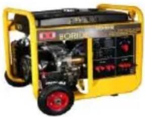
natural_image
Yellow portable gas turbine with red wheels and control panel (no visible text or symbols)

CAUTION: The V_ON and V_OFF can be set via the PC software, the Battery Control Voltage Parameters refer to the chapter 3.4 Setting.
2) Control the load first disconnection and second disconnection.
Battery Voltage ( V_BAT )
Under Voltage Warning Voltage (Muvw)
Under Voltage Warning Recover Voltage ( V_UVWR )
Low Voltage Disconnect Voltage( V_LVD )
Low Voltage Reconnect Voltage( V_LVR )
♦ Utility/Generator Relay normally closed contact:
V_BAT ≤slant V_UVW : The Utility/Generator Relay normally closed contact OFF control the load ① first disconnection;
V_BAT ≥slant V_UVWR : The Utility/Generator Relay normally closed contact ON control the load first connection.
Load Relay:
V_BAT ≤slant V_LVD : The Load Relay OFF control the load 2 second disconnection;
V_BAT ≤slant V_LVR : The Load Relay ON control the load ^2 second connection;

CAUTION: The Battery Control Voltage Parameters refer to the chapter 3.4
Setting.
WARNING: When the system power off, the utility/generator relay normally closed contact is closed, please check the system in time.
Refer to the below the diagram:

flowchart
graph TD
    A["PV"] --> B["Battery"]
    B --> C["Fuse"]
    C --> D["Battery"]
    D --> E["Utility/generator relay normally closed contact"]
    E --> F["Load Relay"]
    F --> G["Battery"]
    G --> H["Second Disconnection"]
    H --> I["First Disconnection"]
    I --> J["Radio Signal"]
    style A fill:#f9f,stroke:#333
    style B fill:#ccf,stroke:#333
    style C fill:#cfc,stroke:#333
    style D fill:#fcc,stroke:#333
    style E fill:#cff,stroke:#333
    style F fill:#ffc,stroke:#333
    style G fill:#cfc,stroke:#333
    style H fill:#fcc,stroke:#333
    style I fill:#ffc,stroke:#333
2.5 Mounting
WARNING: Do not reverse the polarity of the batteries. Reverse polarity will damage the charge controller permanently. Damage caused by reverse polarity, is not covered by warranty.
WARNING: Risk of explosion! Never install the controller in a sealed enclose with flooded batteries! Do not install in a confined area where battery gas can accumulate.
WARNING: Risk of electric shock! The solar array high voltage can cause serious shock or injury. Make use of fuses/breaker or cover the entire solar array, prior to performing any work on change controller.
CAUTION: The controller requires at least 150mm of clearance above and below for proper air flow. Ventilation is highly recommended if mounted in an enclosure.
Installation steps:
Step 1: Determination of Installation Location and Heat-dissipation Space
Determination of installation location: The controller shall be installed in a place with sufficient air flow through the radiators of the controller and a minimum clearance of 150 mm from the upper and lower edges of the controller to ensure natural thermal convection. Please see below Figure
CAUTION: If the controller is to be installed in an enclosed box, it is important to ensure reliable heat dissipation through the box.

text_image
220 300 48 48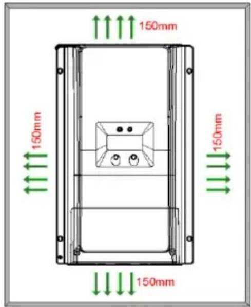
text_image
150mm 150mm 150mm 150mmStep 2: Remove the terminal protective cover
text_image
Tractor 8688 8688 SELECT ENTER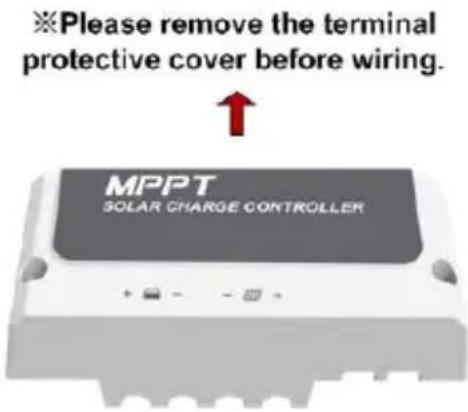
text_image
※Please remove the terminal protective cover before wiring. MPPT SOLAR CHARGE CONTROLLERStep3: Connect the battery①(Left) and PV②(Right)
NOTE: Disconnect the system in the reverse order.

WARNING: Do not reverse the polarity of the batteries. Reverse polarity will damage the controller permanently. Damage caused by reverse polarity, is not covered by warranty.

CAUTION: While wiring the controller do not turn on the breaker or fuse and make sure the leads of "+" and "-" poles are connected correctly.

CAUTION: A fuse which current is 1.25 to 2 times the rated current of the controller be installed on the battery side with a distance from the battery not greater than 150 ~mm .

CAUTION: If an inverter is to be connected to the system, connect the inverter directly battery.
One controller:
flowchart
graph TD
    A["Utility"] --> B["Generator"]
    B --> C["AC/DC Charger"]
    C --> D["BATTERY"]
    D --> E["RS Cable"]
    E --> F["RBVS Cable"]
    F --> G["Fuse"]
    G --> H["Utility/Generator Relay"]
    H --> I["Grounding Terminal"]
    I --> J["Select"]
    J --> K["Breaker"]
    K --> L["Load Relay"]
    L --> M["DC/AC Inverter"]
    M --> N["Computer"]
    style A fill:#f9f,stroke:#333
    style B fill:#ccf,stroke:#333
    style C fill:#cfc,stroke:#333
    style D fill:#fcc,stroke:#333
    style E fill:#cff,stroke:#333
    style F fill:#ffc,stroke:#333
    style G fill:#fcc,stroke:#333
    style H fill:#ffc,stroke:#333
    style I fill:#cfc,stroke:#333
    style J fill:#fcc,stroke:#333
    style K fill:#ffc,stroke:#333
    style L fill:#cfc,stroke:#333
    style M fill:#fcc,stroke:#333
    style N fill:#cfc,stroke:#333
Multiple controllers

flowchart
graph TD
    PV1["PV1"] --> Master1["Master 1"]
    PV7["PV7"] --> Master1
    PV8["PV8"] --> Master1
    Master1 --> Slave7["Slave 7"]
    Master1 --> Slave8["Slave 8"]
    Master1 --> BATTERY1["BATTERY"]
    Master1 --> BATTERY2["BATTERY"]
    Master1 --> Breaker1["Breaker"]
    Master1 --> Fuse1["Fuse"]
    Master1 --> Breaker2["Breaker"]
    Master1 --> RS485["RS485"]
    Master1 --> RS486["RS485"]
    Master1 --> RS485
    Master1 --> RS486
    Master1 --> RS485
    Master1 --> RS486
    Master1 --> RS485
    Master1 --> RS486
    Master1 --> RS485
    Master1 --> RS486
    Master1 --> RS485
    Master1 --> RS486
    Master1 --> RS485
    Master1 --> RS486
    Master1 --> RS485
Step 4: Grounding
Tracer AN series is a common-negative controller, if any of one negative is grounded, all the negative terminals of PV, Battery will be grounded simultaneously. However, according to the practical application, all the negative terminals of PV array, battery and load can also be ungrounded, but the grounding terminal on its shell must be grounded, which may effectively shield the electromagnetic interference from the outside, and prevent some electric shock to human body due to the electrification of the shell.

CAUTION: For common-negative system, such as motorhome, it is recommended to use a common-negative controller; but if in the common-negative system, some common-positive equipment are used, and the positive electrode is grounded, the controller may be damaged.
Step 5: Connect accessories
- Connect the remote temperature sensor cable (Model:RTS300R47K3.81A)
Connect the remote temperature sensor cable to the interface ⑧ and place the other end close to the battery.

CAUTION: If the remote temperature sensor is not connected to the controller,, the default setting for battery charging or discharging temperature is 25 °C without temperature compensation.
- Connect Remote Battery Voltage Sensor (Model:RVBS300B3.81)
Connect the remote battery voltage sensor cable to the interface 11 and connect the other end to the battery terminals.
- Connect the accessories for RS485 communication, refer to the accessories list.
Step 6: Powered on the controller
Turn on the battery fuse to power on the controller, then check the LCD is OFF or the fault indicator is ON when the controller is normal.

CAUTION: If the controller is not operating properly or the battery indicator on the controller shows an abnormality, please refer to 4.2 "Troubleshooting".
3 Operation
text_image
PV SOC BATT. TYPE -88.8 AkWh% LOAD TYPE V °C °F SELECT ENTER3.1 Indicator
| Indicator | Color | Status | Instruction |
 Charging LED indicator Charging LED indicator | Green On | Solid | PV connection normal but low voltage(irradiance) from PV, no charging |
| Green OFF | No PV voltage(night time) or PV connection problem | ||
| Green | Slowly Flashing | In charging | |
| Green | Fast Flashing | PV over voltage | |
| NOTE: The fault indicator refer to the chapter 3.3 "Fault Indication". | |||
3.2 Button
| Button | Function |
| SELECT button | Browse interfaceSetting parameter |
| ENTER button | Load ON/OFFClear errorEnter into Set ModeSave data |
3.3 LCD Display
Status Description
| Item Icon Status | ||
| PV array | Day | |
| Night | ||
| No charging | ||
| Charging | ||
| PV Voltage, Current, Power | ||
| Battery | Battery capacity, In Charging | |
| Battery Voltage, Current, Temperature | ||
| Battery Type | ||
| Load | Load control delay turn ON | |
| Load control delay turn OFF | ||
Browse interface

flowchart
graph TD
    A["98.0V DC power"] --> B["3.3A DC current"]
    B --> C["890 kWh DC power"]
    C --> D["48.9V DC current"]
    D --> E["4.0A DC current"]
    E --> F["16°C DC power"]
    F --> G["000 kWh DC power"]
    G --> H["000A DC power"]
    H --> I["000V DC power"]
    A --> J["LOAD TYPE 2 n"]
    J --> K["LOAD TYPE 117"]
    K --> L["LOAD 000 kWh"]
    L --> M["LOAD 000A"]
NOTE: When no operation, the interface will be automatic cycle, but the follow two interfaces not be display.
▶ Fault Indication
| Status | Fault indicator | charging indicator | Icon Description | |
| Battery over discharged | Red on solid | —— | 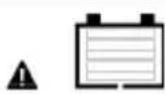 | Battery level shows empty, battery frame blink, fault icon blink. |
| Battery over voltage | Red slowly flashing | —— | 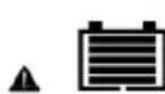 | Battery level shows full, battery frame blink, fault icon blink. |
| Battery over temperature | Red slowly flashing | —— | 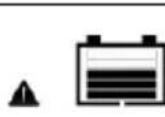 | Battery level shows current value, battery frame blink, fault icon blink. |
| Controller over temperature | Red slowly flashing | Green slowly flashing |  | Battery level shows current value, battery frame blink, fault icon blink. |
| System voltage error | Red slowly flashing | Green fast flashing |  | Battery level shows current value, battery frame blink, fault icon blink. |
3.4 Setting
(1) Clear the generated energy
Operating:
Step 1: Press the "ENTER" button and hold 5s under the PV power interface and the value is flashing.
Step 2: Press the "ENTER" button to clear the generated energy.
(2)Switch the battery temperature unit
Press the "ENTER" button and hold 5s under the battery temperature interface.
(3)Battery type
Battery Type
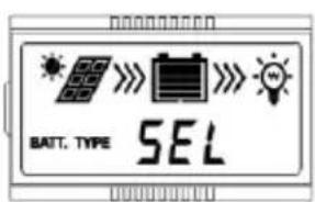
text_image
BATT. TYPE SEL①Sealed (Default)
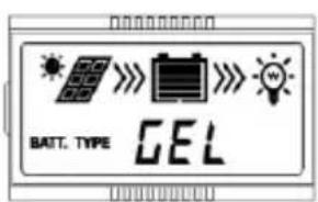
text_image
BATT. TYPE GEL②Gel

text_image
BATT. TYPE FLD③Flooded
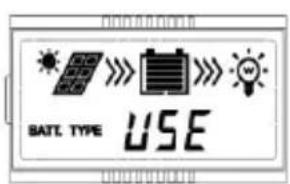
text_image
SATE TYPE USE④ User(Apply to "MT50" and "PC software "Solar Station Monitor")
Operating Steps
Under Battery Voltage interface, long press ENTER button enter into the interface of Battery type setting. After choosing the battery type by pressing SELECT button, waiting for 5
seconds or pressing ENTER button again to modify successfully.
➢ Battery Control Voltage Parameters
The parameters are in 12V system at 25 °C, please double the values in 24V system and quadruple the values in 48V system.
| Battery charging setting | Sealed | Gel | Flooded | User |
| Over Voltage Disconnect Voltage | 16.0V | 16.0V | 16.0V | 9~17V |
| Charging Limit Voltage | 15.0V | 15.0V | 15.0V | 9~17V |
| Over Voltage Reconnect Voltage | 15.0V | 15.0V | 15.0V | 9~17V |
| Equalize Charging Voltage | 14.6V | — | 14.8V | 9~17V |
| Boost Charging Voltage | 14.4V | 14.2V | 14.6V | 9~17V |
| Float Charging Voltage 13.8V 13.8V | 13.8V 9~17V | |||
| Boost Reconnect Charging Voltage | 13.2V 13.2V 13.2V 9~17V | |||
| Low Voltage Reconnect Voltage | 12.6V | 12.6V | 12.6V | 9~17V |
| Under Voltage Warning Reconnect Voltage | 12.2V 12.2V 12.2V 9~17V | |||
| Under Volt. Warning Volt. | 12.0V | 12.0V | 12.0V | 9~17V |
| Low Volt. Disconnect Volt. | 11.1V | 11.1V | 11.1V | 9~17V |
| Discharging Limit Voltage | 10.6V | 10.6V | 10.6V | 9~17V |
| Equalize Duration (min.) | 120 | — | 120 | 0~180 |
| Boost Duration (min.) | 120 | 120 | 120 | 10~180 |
NOTE:
1) When the battery type is sealed, gel, flooded, the adjusting range of equalize duration is 0 to 180min and boost duration is 10 to 180min.
2) The following rules must be observed when modifying the parameters value in user battery type (factory default value is the same as sealed type):
A. Over Voltage Disconnect Voltage > Charging Limit Voltage ≥ Equalize Charging Voltage ≥ Boost Charging Voltage ≥ Float Charging Voltage > Boost Reconnect Charging Voltage.
B. Over Voltage Disconnect Voltage > Over Voltage Reconnect Voltage
C. Low Voltage Reconnect Voltage > Low Voltage Disconnect Voltage ≥ Discharging Limit Voltage.
D. Under Voltage Warning Reconnect Voltage > Under Voltage Warning Voltage ≥ Discharging Limit Voltage.
E. Boost Reconnect Charging voltage > Low Voltage Disconnect Voltage.

CAUTION: Please refer to user guide or contact with the sales for the detail of setting
operation.
4 Protections, Troubleshooting & Maintenance
4.1 Protections
WARNING: Do not reverse the polarity of the batteries. Reverse polarity will damage the charge controller permanently. Damage caused by reverse polarity, is not covered by warranty.
| PV Over Current/power | When the charging current or power of the PV array exceeds the controller's rated current or power, it will be charge at the rated current or power.NOTE: When the PV modules are in series, ensure that the open-circuit voltage of the PV array does not exceed the "maximum PV open-circuit voltage" rating. Otherwise the controller may be damaged. |
| PV Short Circuit | When not in PV charging state, the controller will not be damaged in case of a short-circuiting in the PV array. |
| PV Reverse Polarity | When the polarity of the PV array is reversed, the controller may not be damaged and can continue to operate normally after the polarity is corrected.NOTE: If the PV array is reverse connected to the controller,1.5 times rated controller power(watts)from the PV array, will damage the controller. |
| Night Reverse Charging | Prevents the battery from discharging through the PV module at night. |
| Battery Over Voltage | When the battery voltage reaches the over voltage disconnect voltage, it will automatically stop battery charging to prevent battery damage caused by over-charging. |
| Battery Over Discharge | When the battery voltage reaches the low voltage disconnect voltage, it will automatically stop battery discharging to prevent battery damage caused by over-discharging. (Any controller connected loads will be disconnected. Loads directly connected to the battery will not be affected and may continue to discharge the battery.) |
| Battery Overheating | The controller can detect the battery temperature through an external temperature sensor.The controller stops working when its temperature exceeds 65 °C and restart to work when its temperature is below 55 °C. |
| Controller Overheating* | The controller is able to detect the temperature inside the battery. The controller stops working when its temperature exceeds 85 °C and restart to work when its temperature is below 75 °C. |
| TVS High Voltage Transients | The internal circuitry of the controller is designed with Transient Voltage Suppressors (TVS) which can only protect against high-voltage surge pulses with less energy. If the controller is to be used in an area with frequent lightning strikes, it is recommended to install an external surge arrester. |
★When the internal temperature is 81^ C, the reducing power charging mode which reduce the charging power of 5%, 10%, 20%, 40% every increase 1^ C is turned on. If the internal temperature is greater than 85^ C, the controller will stop charging. But while the temperature decline to be below 75^ C, the controller will resume.
For example Tracer10420AN 48V system:
Reduce charging power mode

line
| Internal temperature°C | Charge power W | | ---------------------- | -------------- | | 75 | 5000 | | 76 | 5000 | | 77 | 5000 | | 78 | 5000 | | 79 | 5000 | | 80 | 5000 | | 81 | 5000 | | 82 | 4800 | | 83 | 4600 | | 84 | 4400 | | 85 | 4000 | | 86 | 3000 | | 87 | 0 | | 88 | 0 | | 89 | 0 | | 90 | 0 | | 91 | 0 |4.2 Troubleshooting
| Faults | Possible reasons | Troubleshooting |
| The LED&LCD is off during daytime when sunshine falls on PV modules properly | PV array disconnection | Confirm that PV and battery wire connections are correct and tight |
| Wire connection is correct, LCD not display | Battery voltage is lower than 8V | Please check the voltage of battery. At least 8V voltage to activate the controller |
Fault LED indicator flashing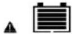 Interface blink Interface blink | Battery voltage higher than over voltage disconnect voltage(OVD) | Check if the battery voltage is too high, and disconnect the solar module |
Fault LED indicator flashing[ATDM]  Interface blink Interface blink | Battery under voltage | Load output is normal, charging LED indicator will return to green automatically when fully charged |
Charging and fault LED indicator flashing[AB23]  Interface blink Interface blink | Battery over temperature | The controller will automatically turn the system off. When the temperature declines to be below 55 °C, the controller will resume. |
4.3 Maintenance
The following inspections and maintenance tasks are recommended at least two times per year for best controller performance.
• Make sure controller firmly installed in a clean and dry ambient.
- Make sure no block on air-flow around the controller. Clear up any dirt and fragments on radiator.
- Check all the naked wires to make sure insulation is not damaged for serious solarization, frictional wear, dryness, insects or rats etc. Repair or replace some wires if necessary.
- Tighten all the terminals. Inspect for loose, broken, or burnt wire connections.
- Check and confirm that LED or LCD is consistent with required. Pay attention to any troubleshooting or error indication .Take necessary corrective action.
- Confirm that all the system components are ground connected tightly and correctly.
- Confirm that all the terminals have no corrosion, insulation damaged, high temperature or burnt/discolored sign, tighten terminal screws to the suggested torque.
- Check for dirt, nesting insects and corrosion. If so, clear up in time.
- Check and confirm that lightning arrester is in good condition. Replace a new one in time to avoid damaging of the controller and even other equipments.

WARNING: Risk of electric shock!
Make sure that all the power is turned off before above operations, and then follow the corresponding inspections and operations.
5 Specifications
Electrical Parameters
| Item/Tracer****AN | 6210 | 5415 | 6415 | 8415 | 10415 | 5420 | 6420 | 8420 | 10420 | |
| Nominal System Voltage | 12/24VDC or Auto | 12/24/36/48VDC or Auto | ||||||||
| Battery Input Voltage Range | 8V~32V | 8V~68V | ||||||||
| Battery Type | Sealed(Default)/Gel/Flooded/User | |||||||||
| Battery fuse | 80A/58V | 125A/58V | 150A/58V | 80A/58V | 125A/58V | 150A/58V | ||||
| Rated charge current | 60A | 50A | 60A | 80A | 100A | 50A | 60A | 80A | 100A | |
| Rated charge Power | 750W/12V1500W/24V | 625W/12V1250W/24V1875W/36V2500W/48V | 750W/12V1500W/24V2250W/36V3000W/48V | 1000W/12V2000W/24V3000W/36V4000W/48V | 1250W/12V2500W/24V3750W/36V5000W/48V | 625W/12V1250W/24V1875W/36V2500W/48V | 750W/12V1500W/24V2250W/36V3000W/48V | 1000W/12V2000W/24V3000W/36W4000W/48V | 1250W/12V2500W/24V3750W/36V5000W/48V | |
| Max. PV open circuit voltage | 100V^3 92Y ^2 | 150V^3 138Y ^2 | 200V^3 180Y ^2 | |||||||
| MPP Voltage Range | (Battery Voltage+2V)~72V ^3 | (Battery Voltage +2V)~108Y ^3 | (Battery Voltage+2V)~144Y ^3 | |||||||
| Tracking efficiency | ≥99.5% | |||||||||
| Max. conversion efficiency | 98.0% | 98.0% | 98.3% | 98.6% | 98.5% | 98.6% | 98.3% | 98.1% | 98.5% | 98.5% |
| Full load efficiency | 97.0% | 97.0% | 97.8% | 98.0% | 98.0% | 98.0% | 97.1% | 97.5% | 97.5% | 97.6% |
| Temperature compensate coefficient | -3mV/°C/2V(Default) | |||||||||
| Self-consumption | 98mA/12V;60mA/24V;50mA/36V;46mA/48V | |||||||||
| Grounding | Common negative grounding | |||||||||
| Relay | Rated Value:5A/30VDC; Max. Value:0.5A/60VDC | |||||||||
| RS485 interface | RS485(5VDC/200mA, Two RJ45 ports in parallel) ^4 | |||||||||
| LCD backlight time | Default:60S,Range:0 ~999S(OS:the backlight is ON all the time) | |||||||||
①At minimum operating environment temperature; ②At 25°C environment temperature;
③The maximum PV open circuit voltage must never exceed 92V(Tracer**10AN),138V(Tracer**15AN)or180V(Tracer**20AN) at 25°C environment temperature.
④When connect the controller to external devices, only one of the ports can be used; when use multiple controllers in parallel, the port are for cascaded use.
Environmental Parameters
| Ambient temperature range | -25°C~+60°C (Derate above 45°C) |
| LCD temperature range | -20°C~+70°C |
| Storage temperature range | -30°C~+85°C |
| Relative humidity range | 5% to 95% (N.C.) |
| Enclosure | IP20 |
| Pollution degree | PD2 |
Mechanical Parameters
| Item | Tracer5415/5420AN | Tracer6210AN | Tracer6415/6420AN |
| Dimension | 261×216×119mm | 340×232×105.2mm | 340×236×119mm |
| Mounting dimension | 180×204mm | 260×220mm | 260×224mm |
| Mounting hole size | Φ7 | ||
| Terminal | 6AWG/16mm ^2 | 2AWG/35mm ^2 | |
| Recommended cable | 6AWG/16mm ^2 | 6AWG/16mm ^2 | |
| Weight | 3.5kg | 3.5kg | 4.5kg |
| Item | Tracer8415/8420AN | Tracer10415/10420AN |
| Dimension | 394 ×240 ×134mm | 394 ×242 ×143mm |
| Mounting dimension | 300×228mm | 300×230mm |
| Mounting hole size | Φ7 | |
| Terminal | 2AWG/35mm ^2 | 2AWG/35mm ^2 |
| Recommended cable | 4AWG/25mm ^2 | 2AWG/35mm ^2 |
| Weight | 6.1kg | 7.4kg |
Certification
| Safety | EN/IEC62109-1 |
| EMC | EN61000-6-3/EN61000-6-1 |
| FCC | 47 CFR Part 15, Subpart B |
| ROHS | IEC62321-3-1 |
Annex I Dimensions
Tracer5415/5420AN Dimensions(Unit:mm)
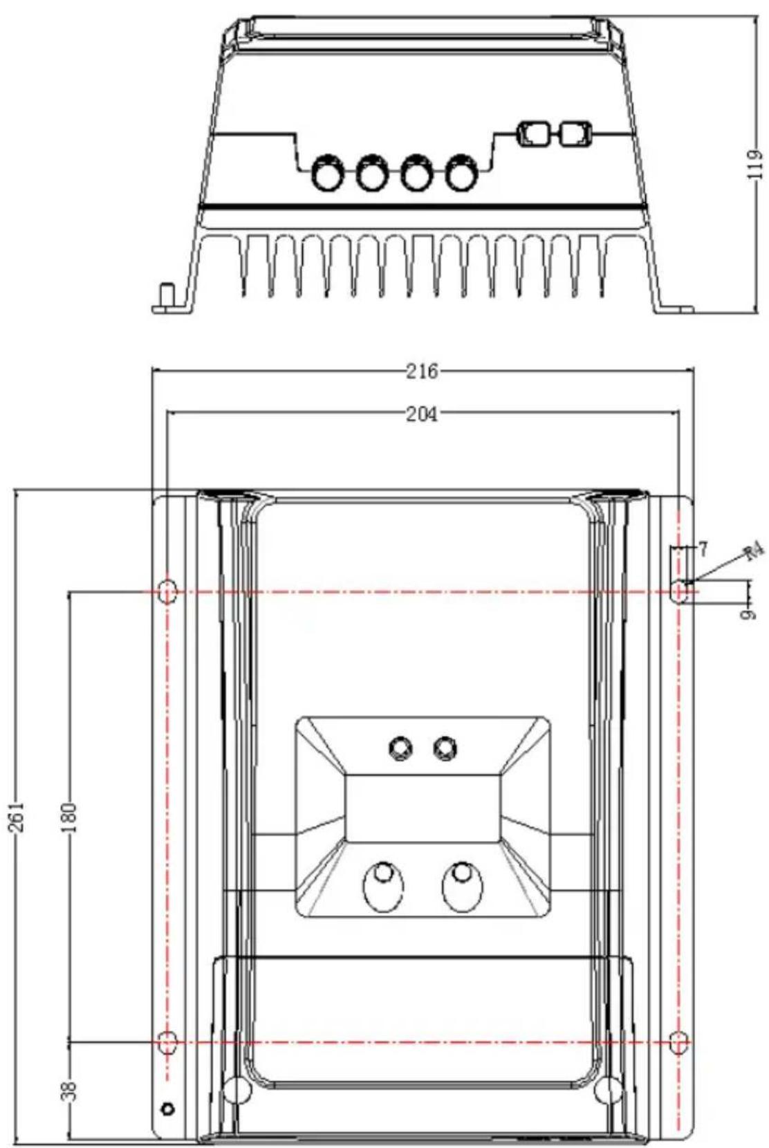
text_image
119 216 204 7 9 261 180 38Tracer6210AN Dimensions(Unit:mm)
natural_image
Technical line drawing of a rectangular electronic component with internal components and mounting base (no text or symbols)
text_image
260 340.21 7 9 220 232Tracer6415/6420AN Dimensions(Unit:mm)
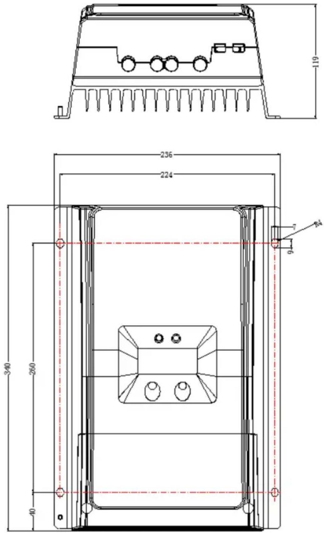
text_image
119 236 224 340 260 40 7 9Tracer8415/8420AN Dimensions(Unit:mm)

text_image
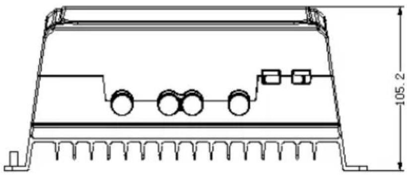
134 240 228 394 300 47 7 9Tracer10415/10420AN Dimensions(Unit:mm)
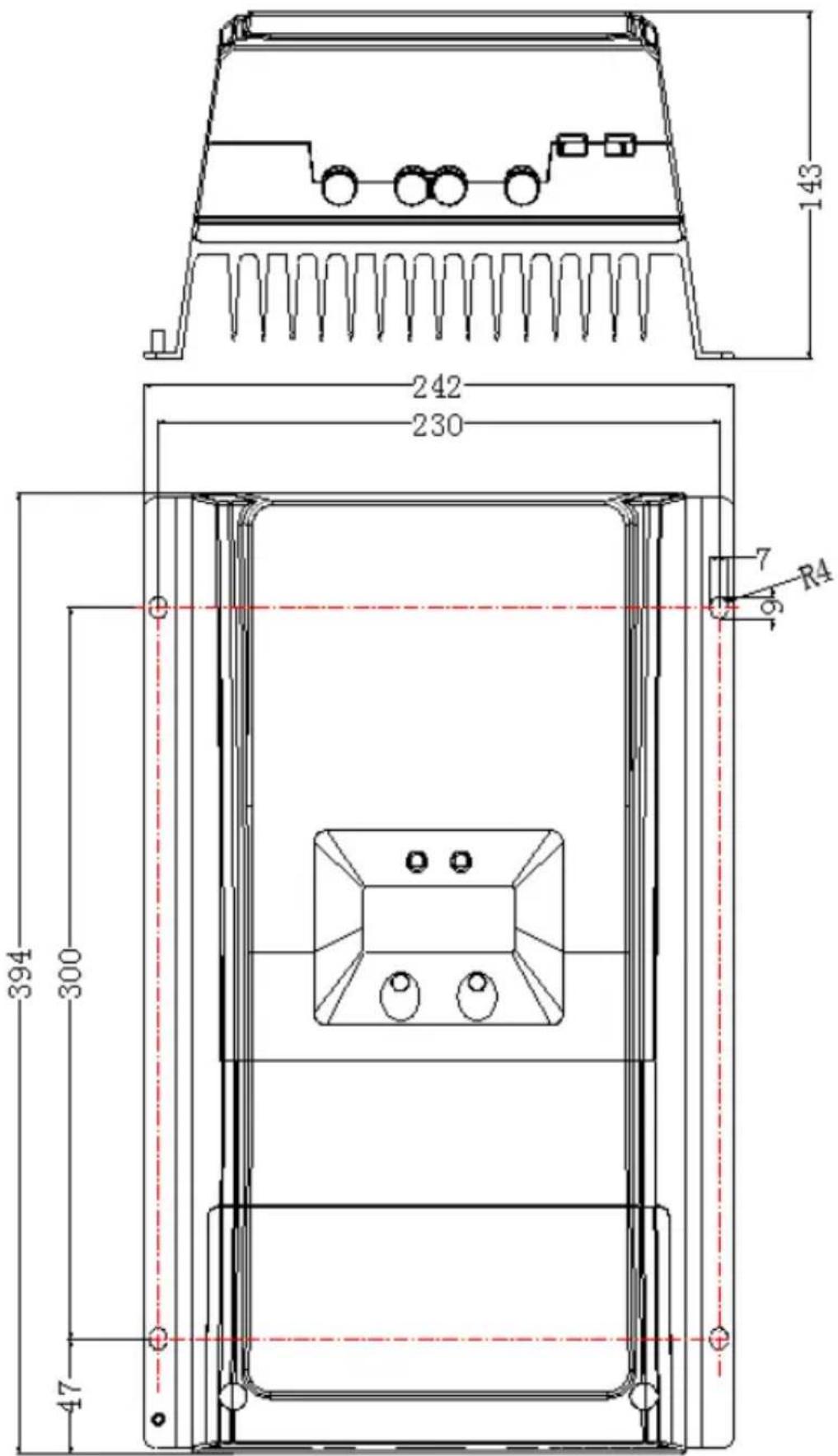
text_image
143 242 230 7 R4 394 300 47Any changes without prior notice! Version number: V1.2