AT-OMNI-232 - Unspecified Atlona - Free user manual and instructions
Find the device manual for free AT-OMNI-232 Atlona in PDF.

User questions about AT-OMNI-232 Atlona
0 question about this device. Answer the ones you know or ask your own.
Ask a new question about this device
Download the instructions for your Unspecified in PDF format for free! Find your manual AT-OMNI-232 - Atlona and take your electronic device back in hand. On this page are published all the documents necessary for the use of your device. AT-OMNI-232 by Atlona.
USER MANUAL AT-OMNI-232 Atlona
Version Release Date Notes
2 Jun 2023 Correction to power supply SKU
Welcome to Atlona!
Thank you for purchasing this Atlona product. We hope you enjoy it and will take a extra few moments to register your new purchase.
Registration only takes a few minutes and protects this product against theft or loss. In addition, you will receive notifications of product updates and firmware. Atlona product registration is voluntary and failure to register will not affect the product warranty.
To register your product, go to https://atlona.com/registration
Sales, Marketing, and Customer Support
Main Office
Atlona Incorporated
70 Daggett Drive
San Jose, CA 95134
United States
Office: +1.877.536.3976 (US Toll-free)
Office: +1.408.962.0515 (US/International)
Sales and Customer Service Hours
Monday - Friday: 6:00 a.m. - 4:30 p.m. (PST)
https://atlona.com/
International Headquarters
Atlona International AG
Ringstrasse 15a
8600 Dübendorf
Switzerland
Office: +41 43 508 4321
Sales and Customer Service Hours
Monday - Friday: 09:00 - 17:00 (UTC +1)
Operating Notes
As of this writing, there are no firmware updates for this product. When new firmware is released, update instructions will be included with the firmware and will be appended to this manual.

IMPORTANT: Visit https://atlona.com/product/AT-OMNI-232 for the latest firmware updates and User Manual.
Atlona, Inc. ("Atlona") Limited Product Warranty
Coverage
Atlona warrants its products will substantially perform to their published specifications and will be free from defects in materials and workmanship under normal use, conditions and service.
Under its Limited Product Warranty, Atlona, at its sole discretion, will either:
- repair or facilitate the repair of defective products within a reasonable period of time, restore products to their proper operating condition and return defective products free of any charge for necessary parts, labor and shipping.
OR
- replace and return, free of charge, any defective products with direct replacement or with similar products deemed by Atlona to perform substantially the same function as the original products.
OR
- refund the pro-rated value based on the remaining term of the warranty period, not to exceed MSRP, in cases where products are beyond repair and/or no direct or substantially similar replacement products exist.
Repair, replacement or refund of Atlona products is the purchaser's exclusive remedy and Atlona liability does not extend to any other damages, incidental, consequential or otherwise.
This Limited Product Warranty extends to the original end-user purchaser of Atlona products and is non-transferrable to any subsequent purchaser(s) or owner(s) of these products.
Coverage Periods
Atlona Limited Product Warranty Period begins on the date of purchase by the end-purchaser. The date contained on the end-purchaser 's sales or delivery receipt is the proof purchase date.
Limited Product Warranty Terms – New Products
• 10 years from proof of purchase date for hardware/electronics products purchased on or after June 1, 2013.
• 3 years from proof of purchase date for hardware/electronics products purchased before June 1, 2013.
• Lifetime Limited Product Warranty for all cable products.
Limited Product Warranty Terms - Refurbished (B-Stock) Products
- 3 years from proof of purchase date for all Refurbished (B-Stock) hardware and electronic products purchased on or after June 1, 2013.
Remedy
Atlona recommends that end-purchasers contact their authorized Atlona dealer or reseller from whom they purchased their products. Atlona can also be contacted directly. Visit https://atlona.com for Atlona's contact information and hours of operation. Atlona requires that a dated sales or delivery receipt from an authorized dealer, reseller or end-purchaser is provided before Atlona extends its warranty services. Additionally, a return merchandise authorization (RMA) and/or case number, is required to be obtained from Atlona in advance of returns.
Atlona requires that products returned are properly packed, preferably in the original carton, for shipping. Cartons not bearing a return authorization or case number will be refused. Atlona, at its sole discretion, reserves the right to reject any products received without advanced authorization. Authorizations can be requested by calling 1-877-536-3976 (US toll free) or 1-408-962-0515 (US/international) or via Atlona's website at https://atlona.com.
Exclusions
This Limited Product Warranty excludes:
- Damage, deterioration or malfunction caused by any alteration, modification, improper use, neglect, improper packaging or shipping (such claims must be presented to the carrier), lightning, power surges, or other acts of nature.
Atlona, Inc. ("Atlona") Limited Product Warranty
- Damage, deterioration or malfunction resulting from the installation or removal of this product from any installation, any unauthorized tampering with this product, any repairs attempted by anyone unauthorized by Atlona to make such repairs, or any other cause which does not relate directly to a defect in materials and/or workmanship of this product.
- Equipment enclosures, cables, power supplies, batteries, LCD displays, and any accessories used in conjunction with the product(s).
- Products purchased from unauthorized distributors, dealers, resellers, auction websites and similar unauthorized channels of distribution.
Disclaimers
This Limited Product Warranty does not imply that the electronic components contained within Atlona's products will not become obsolete nor does it imply Atlona products or their electronic components will remain compatible with any other current product, technology or any future products or technologies in which Atlona's products may be used in conjunction with. Atlona, at its sole discretion, reserves the right not to extend its warranty offering in instances arising outside its normal course of business including, but not limited to, damage inflicted to its products from acts of god.
Limitation on Liability
The maximum liability of Atlona under this limited product warranty shall not exceed the original Atlona MSRP for its products. To the maximum extent permitted by law, Atlona is not responsible for the direct, special, incidental or consequential damages resulting from any breach of warranty or condition, or under any other legal theory. Some countries, districts or states do not allow the exclusion or limitation of relief, special, incidental, consequential or indirect damages, or the limitation of liability to specified amounts, so the above limitations or exclusions may not apply to you.
Exclusive Remedy
To the maximum extent permitted by law, this limited product warranty and the remedies set forth above are exclusive and in lieu of all other warranties, remedies and conditions, whether oral or written, express or implied. To the maximum extent permitted by law, Atlona specifically disclaims all implied warranties, including, without limitation, warranties of merchantability and fitness for a particular purpose. If Atlona cannot lawfully disclaim or exclude implied warranties under applicable law, then all implied warranties covering its products including warranties of merchantability and fitness for a particular purpose, shall provide to its products under applicable law. If any product to which this limited warranty applies is a “Consumer Product” under the Magnuson-Moss Warranty Act (15 U.S.C.A. §2301, ET SEQ.) or other applicable law, the foregoing disclaimer of implied warranties shall not apply, and all implied warranties on its products, including warranties of merchantability and fitness for the particular purpose, shall apply as provided under applicable law.
Other Conditions
Atlona's Limited Product Warranty offering gives legal rights, and other rights may apply and vary from country to country or state to state. This limited warranty is void if (i) the label bearing the serial number of products have been removed or defaced, (ii) products are not purchased from an authorized Atlona dealer or reseller. A comprehensive list of Atlona's authorized distributors, dealers and resellers can be found at https://atlona.com.
Important Safety Information
CAUTION
RISK OF ELECTRIC SHOCK
DO NOT OPEN
CAUTION: TO REDUCT THE RISK OF
ELECTRIC SHOCK
DO NOT OPEN ENCLOSURE OR EXPOSE
TO RAIN OR MOISTURE.
NO USER-SERVICEABLE PARTS
INSIDE REFER SERVICING TO
QUALIFIED SERVICE PERSONNEL.

The exclamation point within an equilateral triangle is intended to alert the user to the presence of important operating and maintenance instructions in the literature accompanying the product.

The information bubble is intended to alert the user to helpful or optional operational instructions in the literature accompanying the product.
- Read these instructions.
- Keep these instructions.
- Heed all warnings.
- Follow all instructions.
- Do not use this product near water.
- Clean only with a dry cloth.
- Do not block any ventilation openings. Install in accordance with the manufacturer's instructions.
-
Do not install or place this product near any heat sources such as radiators, heat registers, stoves, or other apparatus (including amplifiers) that produce heat.
-
Do not defeat the safety purpose of a polarized or grounding-type plug. A polarized plug has two blades with one wider than the other. A grounding type plug has two blades and a third grounding prong. The wide blade or the third prong are provided for your safety. If the provided plug does not fit into your outlet, consult an electrician for replacement of the obsolete outlet.
- Protect the power cord from being walked on or pinched particularly at plugs, convenience receptacles, and the point where they exit from the product.
- Only use attachments/accessories specified by Atlona.
- To reduce the risk of electric shock and/or damage to this product, never handle or touch this unit or power cord if your hands are wet or damp. Do not expose this product to rain or moisture.
- Unplug this product during lightning storms or when unused for long periods of time.
- Refer all servicing to qualified service personnel. Servicing is required when the product has been damaged in any way, such as power-supply cord or plug is damaged, liquid has been spilled or objects have fallen into the product, the product has been exposed to rain or moisture, does not operate normally, or has been dropped.


FCC Statement

text_image
FCFCC Compliance and Advisory Statement: This hardware device complies with Part 15 of the FCC rules. Operation is subject to the following two conditions: 1) this device may not cause harmful interference, and 2) this device must accept any interference received including interference that may cause undesired operation. This equipment has been tested and found to comply with the limits for a Class A digital device, pursuant to Part 15 of the FCC Rules. These limits are designed to provide reasonable protection against harmful interference in a commercial installation. This equipment generates, uses, and can radiate radio frequency energy and, if not installed or used in accordance with the instructions, may cause harmful interference
to radio communications. However there is no guarantee that interference will not occur in a particular installation. If this equipment does cause harmful interference to radio or television reception, which can be determined by turning the equipment off and on, the user is encouraged to try to correct the interference by one or more of the following measures: 1) reorient or relocate the receiving antenna; 2) increase the separation between the equipment and the receiver; 3) connect the equipment to an outlet on a circuit different from that to which the receiver is connected; 4) consult the dealer or an experienced radio/TV technician for help. Any changes or modifications not expressly approved by the party responsible for compliance could void the user's authority to operate the equipment. Where shielded interface cables have been provided with the product or specified additional components or accessories elsewhere defined to be used with the installation of the product, they must be used in order to ensure compliance with FCC regulations.
Table of Contents
Introduction 8
Features 8
Package Contents 8
Panel Description 9
Installation
10
Audio Connector 10
Connection Instructions 10
Connection Diagram 11
Mounting Instructions 12
Configuration 13
IP 13
DHCP mode 13
Auto IP mode 13
Static IP mode 13
Dante Controller 13
AMS
14
System Info
15
Channel Settings
16
General Settings
16
Commands
17
Unit
17
Audio
20
Appendix
23
Specifications
23
Index
25
Introduction
The Atlona OmniStream™ AT-OMNI-232 is a Dante™ networked audio interface that transmits and receives two channels of audio over a network. OmniStream is designed for distributing AV over Gigabit Ethernet in enterprises and other large-scale installations. AT-OMNI-232 devices are ideal for integrating microphones and other audio sources with a Dante-equipped DSP and OmniStream AV decoders. The AT-OMNI-232 features two balanced mic/line audio inputs with selectable 24 volt phantom power, as well as two balanced line level outputs. It can be powered over the network though Power over Ethernet (PoE), as well as from local AC power. The AT-OMNI-232 extends the power and flexibility of the OmniStream networked AV platform, by enabling facility-wide system designs that include complete audio system integration with Dante-based professional audio devices.
Features
• Transmits and receives Dante audio over the network
• 1 Gigabit LAN connection
- Easy routing using Dante Controller
• Balanced audio input and output
- PoE compatible for power from a compatible PoE network switch
- Optional 12V DC power adapter for when a PoE network switch is not available
- Adjustable input gain and output volume
- Compatible with phantom power MICs
Package Contents
1 x OmniStream 232
4 x Captive screw connector (3 pin)
1 x Wall/table mounting brackets
1 x Installation Guide
Panel Description

text_image
ATLONA® PWR 1 DANTE IP BRIDGE OMNISTREAM™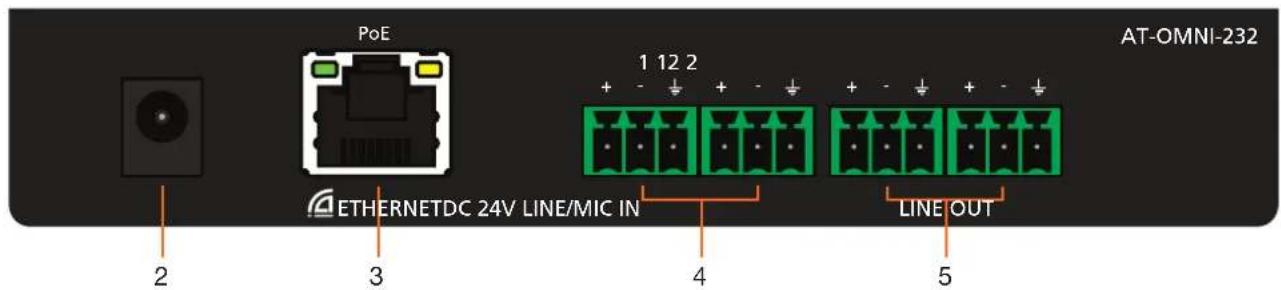
text_image
POE 1 12 2 AT-OMNI-232 ETHERNETDC 24V LINE/MIC IN LINE OUT 2 3 4 51. PWR
This LED indicator is green when the unit is powered.
2. DC 24V
Connect optional power supply (AT-PS-241-NL) for an alternative power source.
3. ETHERNET
Connect to a PoE switch for power and signal distribution.
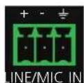
4. LINE/MIC IN
Connect to MICs or other audio sources.
5. LINE OUT
Connect to an audio DSP, amplifier, or other audio players/distribution devices.
Installation
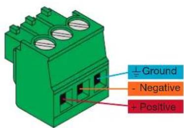
Audio Connector
Connect dynamic, self-powered, wireless, or phantom powered microphones, receivers (or other audio sources) with line level outputs using the included captive screw connectors. Either balanced or unbalanced connections may be used.
- Use wire strippers to remove a portion of the cable jacket.
- Remove at least 3/16" (5 mm) from the insulation of each wire.
- Insert the wires into the correct terminal on the included Phoenix connector, as shown below.
- Tighten the screws to secure the wires. Do not use high-torque devices as this may damage the screws and/or connector block.
text_image
Ground - Negative + PositiveMIC/LINE
Balanced
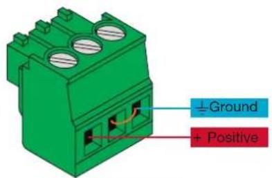
text_image
±Ground + PositiveLINE
Unbalanced

NOTE: Phantom power is set to off by default, to ensure MICs without phantom power are not damaged
NOTE: Use of a jumper is needed between negative and ground ports when using an unbalanced connection
Connection Instructions
- Connect captive screw audio connectors to LINE/MIC IN ports from audio sources (e.g. MICs).

NOTE: Phantom power must be turned on within AMS
- Connect an Ethernet cable to the ETHERNET port.

NOTE: Connect to a PoE enabled switch, if one is not available, a power supply (AT-PS-241-NL) is purchasable through Atlona for local power.
NOTE: To ensure stable connection, disable 802.3 Energy Efficient Ethernet (EEE) on connected Ethernet switches.
-
Connect captive screw connectors from LINE OUT ports to audio players/distribution devices (e.g. AT-PA100-G2).
-
Log onto a local network computer and use the Dante Controller and AMS software to adjust device and audio settings. See page 13 for Dante Controller instructions.
Installation
Connection Diagram

flowchart
graph TD
    A["AT-PA100-G2"] -->|Audio| B["AT-OMNI-232"]
    B -->|Audio| C["Laptop"]
    B -->|Audio| D["Dante DSP"]
    D -->|Ethernet| E["LAN"]
    E -->|Control| F["Control System"]
    B -->|Audio| G["MIC"]

flowchart
graph TD
    A["AT-OMNI-232"] -->|Ethernet| B["Dante DSP"]
    C["AT-OMNI-121"] -->|Audio Audio| B
    D["AT-OMNI-112"] -->|Video| B
    E["Laptop"] -->|Video| B
    F["Display"] -->|Video| B
    G["MIC"] -->|Audio Audio| B
    B -->|Ethernet| H["LAN"]
    H -->|Ethernet| B
    H -->|Ethernet| C
    H -->|Ethernet| D
Mounting Instructions
The AT-OMNI-232 includes two mounting brackets and four mounting screws, which can be used to attach the unit to any flat surface.
- Using a small Philips screwdriver, remove the two screws from the left side of the enclosure.

natural_image
3D rendering of a black electronic device with labeled ports and connectors (no readable text or symbols)- Position one of the rack ears, as shown below, aligning the holes on the side of the enclosure with one set of holes on the rack ear.
- Use the enclosure screws to secure the rack ear to the enclosure.
- To provide added stability to the rack ear, use two of the included screws and attach them to the two holes, directly below the enclosure screws, as shown below.
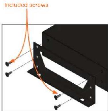
text_image
Included screws
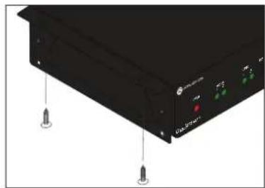
NOTE: Rack ears can also be inverted to mount the unit under a table or other flat surface, as shown below.
- Repeat steps 1 through 4 to attach the second rack ear to the opposite side of the unit.
- Mount the unit using the oval-shaped holes, on each rack ear. If using a drywall surface, a #6 drywall screw is recommended.
natural_image
Black electronic device with labeled ports and screw holes (no readable text or symbols)Configuration
IP
DHCP mode
By default, the OmniStream 232 is set to DHCP mode. In this mode, each encoder that is connected to the Local Area Network (LAN), will automatically be assigned an IP address by the DHCP server.
Auto IP mode
If no DHCP server is detected after 30 seconds, then the encoder will be placed in Auto IP mode and will be assigned a link-local IP address of 169.254.XXX.XXX.
Static IP mode
After initial discovery, either through DHCP or Auto IP mode, a static IP can be set through Dante Controller.
Dante Controller
For network setting changes and I/O audio switching, Dante Controller is needed.
To download the software, go to http://www.audinate.com. The software will be found under products > software > Dante Controller. The download button is found on the right side of the page. Follow the instructions for downloading.
Once downloaded and installed, the AT-OMNI-232 will be automatically detected as long as the PC running Dante Controller and OmniStream 232 are on the same network.

text_image
Dante Controller - Network View File Device View Help Routing Device Info Clock Status Network Status Events Dante™ Filter Transmitters Filter Receivers Dante Transmitters AT0M1232-076d39 Dante Receivers AT0M1232-076d39
NOTE: Connection issues may occur if control software is used over VPN. Ensure the software and OMNI-232 are on the same network
After initial set up and audio routing is done through Dante Controller, then AMS can be used to control audio settings.
AMS
AMS is used for adjusting device settings such as: input volume, output volume, phantom power, and updating.
- Download AMS software from https://atlona.com/products/AT-SW-AMS/
- Launch the Atlona Management System from the Windows desktop or from the Start Menu.
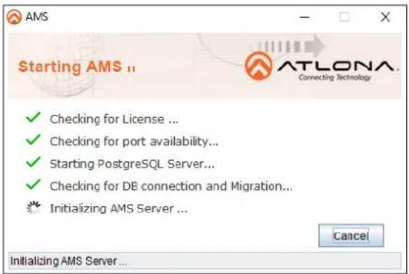
text_image
Starting AMS ✓ Checking for License ... ✓ Checking for port availability... ✓ Starting PostgreSQL Server... ✓ Checking for DB connection and Migration... ♥ Initializing AMS Server ... ATLONA. Connecting Technology Cancel Initializing AMS Server ...
text_image
Message Server started successfully... OK- After the AMS server starts, click the OK button to dismiss the dialog.
- Launch a web browser and type localhost:8080 in the address bar, as shown below.

text_image
localhost localhost:8080- Enter the login information on the AMS web page, then click the Login button. Note that the password is masked when typed.
Login: admin
Password: admin123

text_image
ATLONA Community Technology Username: admin Password: ********** Remember my Username Forgot Password? Login Clear- Under the Domain View, locate the IP address for the OMNI-232

text_image
Start Domain View Global OMNI-232 - 192.168.0.50If no OMNI 232 is found:
• Make sure that both OMNI-232 and AMS are on the same network.

IMPORTANT: OmniStream uses mDNS as the discovery mechanism. In order for mDNS to function properly, there must not be restrictions applied to the network. VPN can be used to connect to a computer that is running AMS, on the same network. However, VPN cannot be used when AMS is running on the local machine.
- Wait 60 seconds for OMNI-232 to be auto discovered.
• If the OMNI-232 is not discovered even after verifying network and waiting 60 seconds, follow the next steps:
a. Remove any network restrictions that may be in place.
b. In AMS, click Start > Add Device > Auto > Stop mDNS Discovery. This feature is enabled by default.

text_image
Start Add Device Site Configuration Auto Manual Discovery Settings Network Stop mDNS Discoveryc. A message box will display when complete. Click the OK button to dismiss the message box.
d. Restart the mDNS listener by clicking Start > Add Device > Auto > Start mDNS Discovery.
e. After the mDNS listener is enabled, click the OK button to dismiss the message box.
f. The OMNI-232 should now be listed under the Domain View pane.
If OMNI-232 is found:
System Info

text_image
System Info Channel Settings General Settings Device Info Model AT-OMNI-232 Version 1.0 MAC Address 00-1d-c1-07-cf-23 Reload SaveThe System Info page will display basic information for the OMNI-232.
Model Number
Will display the unit's SKU, it will always say AT-OMNI-232
Version
Will display the firmware version. This will help ensure the unit is up to date
MAC Address
This identifies the unit
Channel Settings
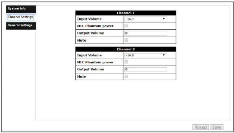
text_image
System Info Channel Settings General Settings Channel 1 Input Volume -16.9 MIC Phantom power Output Volume 0 Mute Channel 2 Input Volume -16.9 MIC Phantom power Output Volume 0 Mute Reload SaveAdjust audio and line settings
Input Volume
Adjusts the audio gain on the input side
- Selections = -16.9, -1.9, 0.0, 15.0, 13.1, 30.0, 28.1, and 45.0
MIC Phantom power
Select to pass power to a Phantom Power MIC
- Default is off, to ensure no MICs are accidentally damaged when plugged in
Output Volume
Adjust output volume
- Settings are from -60 to 0
Mute
Select the checkbox to mute or unmute the output volume

NOTE: Settings cannot be saved unless both output volumes have a value set
General Settings
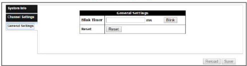
text_image
System Info Channel Settings General Settings General Settings Blink Timer ms Blink Reset Reset Reload SaveBlink Timer:
Sets the amount of time the front panel PWR LED will blink for - This helps to find the correct unit when multiple are present.
- Settings are from 0 (not blinking) to 65535 (ms)
Blink button:
Press this button to initiate the front panel PWR LED blinking
Reset
Resets the OMNI-232 to factory settings
Commands
Unit
Commands are sent using UDP on port 49494
Each command is case sensitive, do not change: capitalization, spacing, or lettering
Each command is terminated with a carriage return
If the command fails or is incorrect the feedback should be "NACK command"
| Command Description | |
| Blink Blinks the power LED on the unit's front panel | |
| Blink ms Sets how long the front panel power LED blinks | |
| GetMAC Displays the MAC address of the unit | |
| Model Displays the unit SKU | |
| Mreset Sets the unit back to factory default | |
| Query Displays the settings of the unit |
Commands
Blink
Blinks the power LED on the unit's front panel
Syntax
Blink X
Parameter Description Range
X State 0 (off), 1 (on)
Example
Blink 1
Feedback
ACK Blink 1
Blink ms
Sets how long the front panel power LED blinks
Syntax
Blink Xms
Parameter Description Range
X Duration up to 65,535
Example
Blink 30000ms
Feedback
ACK Blink 30000ms
GetMAC
Displays the MAC address of the unit
Syntax
GetMAC
Example
GetMAC
Feedback
ACK XX:XX:XX:XX:XX
Model
Displays the unit SKU
Syntax
Model
Example
Model
Feedback
ACK Model = AT-OMNI-232
Commands
Mreset
Sets the unit back to factory default
Syntax
Mreset
Example
Mreset
Feedback
ACK Mreset
Query
Displays the settings of the unit
Syntax
Query
Example
Query
Feedback
ACK Query VIN1=# VIN2=# VOUT1=# VOUT2=#
VOUTMute1=# VOUTMute2=# MicPP1=# # MicPP2=# #
Blink=#
Commands
Audio
Commands are sent using UDP on port 49494
Each command is case sensitive, do not change: capitalization, spacing, or lettering
Each command is terminated with a carriage return
If the command fails or is incorrect the feedback should be "NACK command"
| Command Description | |
| MicPP Turns phantom power on/off for each input | |
| Recall Loads the previously saved settings | |
| Save Saves the current audio settings to memory | |
| VIN Adjust the gain of the audio input channels | |
| VOUT Adjusts the volume level of the output channels | |
| VOUTMute Mutes/unmutes the output audio channels |
Commands
MicPP
Turns phantom power on/off for each input
Syntax
MicPP XY
Parameter Description Range
X Channel 0 (both), 1, 2
Y State 0 (off), 1 (on)
Example
MicPP 1 1
Feedback
ACK MicPP 1 1
Recall
Loads the previously saved settings
Syntax
Recall X
Parameter Description Range
X Save # 0 to 9
Example
Recall 1
Feedback
ACK Recall 1
Save
Saves the current audio settings to memory
Syntax
Save X
Parameter Description Range
X Memory # 0 to 9
Example
Save 3
Feedback
ACK Save 3
Commands
VIN
Adjust the gain of the audio input channels
Syntax
VIN X Y
Parameter Description Range
| X Channel 0 (both), 1, 2 | |
| Y Level -16.9, -1.9, 0.0, 13.1, 15.0, 28.1, 30.0, 45.0 |
Example
VIN 1 15.0
Feedback
ACK VIN 1 15.0
VOUT
Adjusts the volume level of the output channels
Syntax
VOUT X Y
Parameter Description Range
| X Channel 0 (both), 1, 2 | |
| Y Level -60 to 0 |
Example
VOUT 0 -30
Feedback
ACK VOUT 0 -30
VOUTMute
Mutes/unmutes the output audio channels
Syntax
VOUTMute X Y
Parameter Description Range
| X Channel 0 (both), 1, 2 | |
| Y State 0 (off), 1 (on) |
Example
VOUTMute 0 1
Feedback
ACK VOUTMute 0 1
Appendix
Specifications
| Audio | ||
| In/Out Dante two channel | ||
| Input Level +4 dBu nominal, +24 dBu no clipping | ||
| Output Level +4 dBu nominal, +24 dBu no clipping | ||
| Frequency Response 20 Hz to 20 kHz ±5dB | ||
| Input Impedance >1.8 kΩ | ||
| Phantom Power +24V | ||
| Noise THD+N | < 0.015% from 20 Hz to 20 kHz@ 45 dB gain | SNR>90 dB unweighted |
| Distance |
| Max distance dependent on Network configuration |
| Temperature Fahrenheit Celsius | ||
| Operating 32 to 122 0 to 50 | ||
| Storage -4 to 140 -20 to 60 | ||
| Humidity (RH) 20% to 90%, non-condensing | ||
| Power | |
| Consumption | 3.1W |
| Supply | Input: AC 24VAC 50/60HzOutput: DC 24V 1A |
| SKU | AT-PS-241-NL |
Appendix
| Dimensions Inches Millimeters | ||
| H x W x D 1.06 x 6.46 x 3.46 27 x 164 x 88 | ||
| Weight Pounds Kilograms | ||
| Device | 0.82 0.37 | |
| Certification | |
| Power Supply CE, FCC, cULus, RoHS, CCC, RCM | |
| Product CE, FCC | |
Index
A
AMS
discovery 15
set up & login 14
Audio
commands 20
gain 16,22
mute 16,22
output level 16,22
settings
recall 21
save 21
B
Blink 16, 18
timer 16, 18
C
Commands
Blink 18
Blink ms 18
GetMAC 18
MicPP 21
Model 18
Mreset 19
Query 19
Recall 21
Save 21
VIN 22
VOUT 22
VOUTMute 22
Connection
diagram 10
instructions 10
Connector
ethernet 9,10
line/MIC in 9,10
line out 9, 10
Contents
package 8
Customer support 3
D
Dante Controller 13
F
FCC statement 6
Features 8
Feedback
command 17,20
Firmware
version 15
|
Installation 10
IP
auto 13
DHCP 13
static 13
M
MAC address 15, 18
MIC
Phantom Power 10, 16, 21
Model
command 18
number 15
Mreset
command 19
Mute 16,22
0
Operating notes 3
P
Panel descriptions 9
Power
LED 9
supply 9
Q
Query
command 19
R
Recall
command 21
saved settings 21
Reset 16, 19
S
Safety information 6
Save
command 21
Settings
displaying 19
recalling 21
Software
AMS 14
Dante 13
Specifications 23
U
UDP
port 17,20
Unit
commands 17
V
Volume
input 16,22
mute 16,22
output 16,22
W
Warranty 4