
AT-HD-V24M - Electronics Atlona - Free user manual and instructions
Find the device manual for free AT-HD-V24M Atlona in PDF.


| Product Type | 2x4 HDMI Matrix Switcher |
| Brand | Atlona |
| Model | AT-HD-V24M |
| Number of Inputs | 2 (HDMI) |
| Number of Outputs | 4 (HDMI) |
| Supported Resolutions | Up to 1080p and 1920x1200 (WUXGA); includes 480i/p, 576i/p, 720p, 1080i |
| HDCP Compliance | Yes |
| Control Methods | Front panel buttons, IR remote, RS-232 serial |
| Power Supply | 12V DC via universal AC/DC adapter (100-230V, 50/60Hz) |
| Audio Support | DTS-HD Master Audio, Dolby True-HD, Dolby Digital Plus |
| Video Support | HDMI and DVI formats; Deep Color 12-bit |
| Data Rate per Channel | 250 Mbps to 2.25 Gbps |
| Total Link Speed | Up to 6.75 Gbps |
| IR Extender Distance | Up to 1000 ft (300 m) with 38 kHz frequency |
| RS-232 Settings | 9600 baud, 8 data bits, no parity, 1 stop bit (8N1) |
| Safety Certifications | CE, FCC, RoHS |
| Warranty | 3 years limited |
| Package Contents | Matrix switcher, instruction manual, IR remote, AC/DC adapter, 19" ear mount pair, IR extender receiver, RS-232 package (DVD drive & cable) |
| Maintenance and Cleaning | Unplug before cleaning; use a damp cloth; do not use cleaning fluids or aerosols |
| Safety Notes | Do not expose to rain/moisture; use only included power supply; avoid excessive humidity or temperature extremes |
Frequently Asked Questions - AT-HD-V24M Atlona
User questions about AT-HD-V24M Atlona
0 question about this device. Answer the ones you know or ask your own.
Ask a new question about this device
Download the instructions for your Electronics in PDF format for free! Find your manual AT-HD-V24M - Atlona and take your electronic device back in hand. On this page are published all the documents necessary for the use of your device. AT-HD-V24M by Atlona.
USER MANUAL AT-HD-V24M Atlona
5.1 Front Panel 2
5.2 Rear Panel 3
- Remote Control 3
- IR Extender 4
7.1 IR Extender Connection 4
7.2 The IR Extender Components Setup 4
- RS-232 Serial Interface 5
8.1 RS-232 Serial Interface Connect a PC or Control System 5
8.2 RS-232 5
8.3 Commands 5
- RS-232 Serial Commands 6
9.1 Standby Mode 6
9.2 Power Off Mode 6
9.3 Front Panel Lock 6
9.4 Unit Reset 6
-
Typical Application 7
-
Safety Information 8
- Warranty 9
- Atlona Product Registration 10
PACKAGE CONTENTS:
• 2x4 HDMI Matrix Switcher (AT-HD-V24M)
- Instruction Manual
- IR Remote Control
• Universal AC/DC power adapter: 12VDC
• 19 inch Ear mount pair
- IR Extender receiver
• RS232 package (RS232 DVD Drive & RS232 Cable)
INTRODUCTION
Atlona Technologies' AT-HD-V24M is a 2x4 HDMI Matrix Switcher with audio designed to work as a switcher for multiple Audio/Video sources and displays. This Atlona unit is capable of switching HDMI signals between two sources and four displays. Because it is a matrix switch, any or all of the 2 inputs can simultaneously be switched to any or all of the outputs. This devise will support high definition video in multiple resolutions of up to 1080p or 1920x1200. This unit has quick and easy installation. With manual, RS232, as well as IR Remote control options, Atlona's AT-HD-V24M Matrix Switcher is HDCP Compliant making it is perfect for all HDMI devices, PC monitors, Plasma TV displays and HDTVs.
FEATURES:
- Switches HDMI Video signal with Audio between 2 sources and 4 displays.
- Matrix Switch: each input can be directed to any or all outputs at the same time
- Quick and easy installation
• HDMI digital video/audio format, DVI format and HDCP compliant
• Supports link speeds of up to 6.75 Gbps
• Supports wide range of PC resolutions from VGA to WUXGA 1920x1200 and HDTV/DTV resolutions 480i/480p, 576i/576p, 720p, 1080i, 1080p - Compatible with all HDMI devices, PC monitors, Plasma TV display and HDTV
• Supports Digital Video TMDS formats in Deep Color 12bits - Support IR Remote and IR Extender with distance 300M Maximum.
- Various User Interface control:
- IR remote control
- Manual controlled by Front Panel button
- RS232 Control
- Automatically scanning input status by LED on front panel
SPECIFICATIONS
• 2x4 HDMI Matrix Switcher: 2 HDMI Inputs To 4 HDMI Outputs,
- Input Signals: Video (TMDS) 0.5\~1.0Vpp, DDC 5Vpp
• Signal Supports : HDMI Standard, DVI and HDCP Compliant
• Video Supported: HDMI and DVI formats up to 1080p or 1920x1200
• Audio Supported: DTS-HD Master Audio, Dolby True -HD & Dolby Digital Plus
• Supports digital video standards such as:
RGB/YCBCR: 24/30/36-bits
YCBCR: 8/10/12/16/20/24-bits
Double data rate interface for RGB/YCBCR: 12/15/18-bits
- Controls: IR, IR EXT, RS232, and Select buttons on the front panel
• Data Rates: 250Mbps to 2.25Gbps. - IR Extender Distance: 1000ft maximum.
- IR frequency: 38KHz.
• Safety Approvals: CE, FCC, RoHS.
• Power Supply: 12V DC - Use Universal Switch Type 50/60Hz,100/230V
PANEL DESCRIPTIONS
1. Front Panel

- POWER SWITCH. The power switch turns the unit on and off. The LED will illuminate red to indicate that the switcher is ON
- INPUT SOURCES STATUS DISPLAY. Input sources 1 to 2 LEDs illuminate blue to indicate desired video source is present on that input.
- OUTPUT SOURCES STATUS DISPLAY. Output Status shows by LED display.
- SOURCES SELECT BUTTONS. Separate outputs 1 \~ 2 source select buttons are provided. Select sources are 1-HDMI, 2-HDMI.
- IR SENSOR. The IR sensor receives IR commands from the supplied remote control.
- SOURCE SETUP BUTTONS. Setup the inputs 1 \~ 2
-
19 INCH EAR MOUNT PAIR. 19 inch case Ear Mount pair
-
Rear Panel
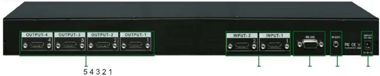
- DC POWER INLET. Power Input: 12VDC
- IR EXTENDER CONTROL. Support one of IR Extender' extend distance maximum 300 Meters.
- RS 232 CONNECTION. DB-9pin Female connector for serial RS-232 control.
- VIDEO INPUTS: HDMI Inputs 1, 2. HDMI Female connector. (Unit can be used with HDCP compliant DVI digital video signals with appropriate)
- VIDEO OUTPUTS: HDMI Outputs 1\~4. HDMI Female connector. (Unit can be used with HDCP compliant DVI digital video signals with appropriate)
REMOTE CONTROL
Ensure the mains voltage supply matches the label on the supplied plug-Pack (+/- 10%)
Ensure that the power switch is OFF
Connect all audio video sources and destination equipment
Power up all HD Source and Displays
For each desired output select the appropriate input by using the front panel select buttons, IR remote control, or the RS232 serial communications port.
When powering up the AT-HD-V24M will return to its last used setting before Powered down.
(Select sources with selection button)
- INPUT 2 SOURCES SELECTION
(Select sources with selection button)

1. IR Extender Connection
REAR PANEL IR EXTENDER PORT

2. The IR Extender Components Setup


flowchart
graph LR
    A["Step 2"] --> B["Cable"]
    B --> C["Step 3"]
    C --> D["Solder"]
    D --> E["Signal"]
    E --> F["Cable"]
    style A fill:#f9f,stroke:#333
    style B fill:#ccf,stroke:#333
    style C fill:#cfc,stroke:#333
    style D fill:#fcc,stroke:#333
    style E fill:#cff,stroke:#333
    style F fill:#ffc,stroke:#333

RS-232 SERIAL INTERFACE CONNECT a PC or CONTROL SYSTEM

| Pin RS-232 Definition | |
| 1 - Not used | |
| 2 TX Transmitter | |
| 3 RX Receiver | |
| 4 - Not used | |
| 5 GND Ground | |
| 6 - Not used | |
| 7 - Not used | |
| 8 - Not used | |
| 9 - Not used |
RS-232
Atlona Technologies' switcher can be controlled via the RS-232 serial control port to allow for interfacing to a PC, The serial communication parameters are 9600 baud, 8 bit, No Parity and 1 stop bit - this is often referred to as 9600 8N1.
When the unit recognizes a complete command it will perform the requested action - there is no delimiter character required. The unit does not send out a message when a value is changed from the front panel or by IR control. If the unit needs to be controlled via the front panel in addition to the RS232 control, you should regularly poll the unit status to ensure the control system accurately reflects the current settings or similar third party control system.
COMMANDS
To Switch Inputs to Outputs
SBIOXO0Y- Where X is Output Number (1-4) and Y is Input Number (1-2)
Unit will respond with
SBUD0XOY- Where X is Output Number (1-4) and Y is Input Number (1-2)
Example : Send Input 2 to Output 3
SBI02O03-Send
SBUD02O3-Rcvd
STANDBY MODE
Note: Turning the unit System Power Off over RS232 will distinguish the LED display leaving only the Power Switch LED on. The Video and Audio outputs will also mute. While the unit is turned off by RS232 it will continue to accept and act upon switching commands. For example, if the unit is in the off mode (via RS232) and you send a command to switch an input to an output, that route will complete and the video and audio will now appear on that channel only. The front panel LED for that particular output will also show the input selected (for that single output channel only). The remaining LED's will remain off and video and audio outputs muted. The unit will still return status and change messages in response to commands sent while in Power Off state. A hard reset command (SBALLRST) will return the unit to normal operation and also unlock the front panel.
POWER OFF MODE
SBSYSMOF- Put system into Standby (Soft Power Off)
SBSYSMON- Bring unit out of Standby (Soft Power On)
Unit will respond with
SBALOFAK- Unit is in Standby
SBALONAK- Unit is no longer in Standby
Example : Put Unit in Standby (Soft Power)
SBSYSMOF-Send
SBALOFAK-Rcvd
FRONT PANEL LOCK
Note : Hard resetting the unit will unlock the Front Panel controls.
SBSYSMLK- When front panel is locked, changes can only be made by RS-232
SBSYSMUK- Front Panel Unlock
Unit will respond with
SBSYSLOK- Front Panel has been Locked
SBSYSULK- Front Panel has been Unlocked
Example : Lock Front Panel Buttons
SBSYSMLK-Send
SBSYSLOK-Rcvd
UNIT RESET
SBALLRST - Reset every output to Input 1
Unit will respond with
SBRSTACK- Unit has reset each Output to Input 1
Example : Reset all outputs to Input 1
SBALLRST-Send
SBRSTACK-Rcvd
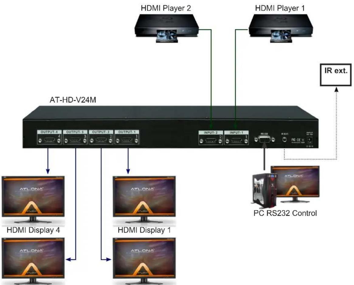
flowchart
graph TD
    A["AT-HD-V24M"] --> B["OUTPUT-4"]
    A --> C["OUTPUT-3"]
    A --> D["OUTPUT-2"]
    A --> E["OUTPUT-1"]
    A --> F["INPUT-2"]
    A --> G["INPUT-1"]
    A --> H["RS 232"]
    A --> I["IR ext."]
    J["HDMI Display 4"] --> A
    K["HDMI Display 1"] --> A
    L["PC RS232 Control"] --> A
    M["HDMI Player 1"] --> A
    N["HDMI Player 2"] --> A
HDMI Display 3 HDMI Display 2
SAFETY INFORMATION
Safeguards
To reduce the risk of electric shock, do not expose this product to rain or moisture.
If the wall plug does not fit into your local power socket, hire an electrician to replace your obsolete socket.
Do not modify the wall plug. Doing so will void the warranty and safety features.
This equipment should be installed near the socket outlet and the device should be easily accessible in case it requires disconnection.
Precautions
FCC Regulations state that any unauthorized changes or modifications to this equipment not expressly approved by the manufacturer could void the user's authority to operate this equipment.
Operate this product using only the included external power supply. Use of other power supplies could impair performance, damage the product or cause fires.
In the event of an electrostatic discharge, this device may automatically turn off. If this occurs, unplug the device, and plug it back in.
Protect and route power cords so they will not be stepped on or pinched by anything placed on or against them. Be especially careful of plug-ins, or cord exit points from this product.
Avoid excessive humidity, sudden temperature changes or temperature extremes.
Keep this product away from wet locations such as bathtubs, sinks, laundries, wet basements and swimming pools.
Use only accessories recommended by ATLONA to avoid fire, shock or other hazards.
Unplug the product before cleaning. Use a damp cloth for cleaning. Do not use cleaning fluid or aerosols, which could enter the unit and cause damage, fire or electrical shock. Some substances may also mar the finish of the product.
Never open or remove unit panels or make any adjustments not described in this manual. Attempting to do so could expose you to dangerous electrical shock or other hazards. It may also cause damage to your AT-HD-V24M. Opening the product will void the warranty.
Do not attempt to service the unit. Instead disconnect it and contact your Authorized ATLONA reseller or contact ATLONA directly.
WARRANTY
1. LIMITED WARRANTY
Atlona Technologies warrants that (a) its products (the “Product”) will perform substantially in accordance with the accompanying written materials for a period of 3 YEARS from the date of receipt and (b) that the Product will be free from defects in materials and workmanship under normal use and service for a period of 3 years. In the event applicable law imposes any implied warranties, the implied warranty period is limited to 3 years from the date of receipt. Some jurisdictions do not allow such limitations on duration of an implied warranty, so the above limitation may not apply to Customer.
2. CUSTOMER REMEDIES
Atlona Technologies and its suppliers' entire liability and Customer's exclusive remedy shall be, at Atlona Technologies' option, either return of the price paid for the Product, or repair or replacement of the Product that does not meet this Limited Warranty and which is returned to Atlona Technologies with a copy of Customer's receipt. This Limited Warranty is void if failure of the Product has resulted from accident, abuse, or misapplication. Any replacement Product will be warranted for the remainder of the original warranty period or 3 year, whichever is longer.
3. NO OTHER WARRANTIES
TO THE MAXIMUM EXTENT PERMITTED BY APPLICABLE LAW, ATLONA TECHNOLOGIES AND ITS SUPPLIERS DISCLAIM ALL OTHER WARRANTIES, EITHER EXPRESS OR IMPLIED, INCLUDING, BUT NOT LIMITED TO IMPLIED WARRANTIES OF MERCHANTABILITY AND FITNESS FOR A PARTICULAR PURPOSE, WITH REGARD TO THE PRODUCT AND ANY RELATED WRITTEN MATERIALS. THIS LIMITED WARRANTY GIVES CUSTOMER SPECIFIC LEGAL RIGHTS. CUSTOMER MAY HAVE OTHER RIGHTS DEPENDING ON THE JURISDICTION.
4. NO LIABILITY FOR DAMAGES
TO THE MAXIMUM EXTENT PERMITTED BY APPLICABLE LAW, IN NO EVENT SHALL ATLONA TECHNOLOGIES OR ITS SUPPLIERS BE LIABLE FOR ANY DAMAGES WHATSOEVER (INCLUDING WITHOUT LIMITATION, SPECIAL, INCIDENTAL, CONSEQUENTIAL, OR INDIRECT DAMAGES FOR PERSONAL INJURY, LOSS OF BUSINESS PROFITS, BUSINESS INTERRUPTION, LOSS OF BUSINESS INFORMATION, OR ANY OTHER PECUNIARY LOSS) ARISING OUT OF THE USE OF OR INABILITY TO USE THIS PRODUCT, EVEN IF ATLONA TECHNOLOGIES HAS BEEN ADVISED OF THE POSSIBILITY OF SUCH DAMAGES. IN ANY CASE, ATLONA TECHNOLOGIES' AND ITS SUPPLIERS' ENTIRE LIABILITY UNDER ANY PROVISION OF THIS AGREEMENT SHALL BE LIMITED TO THE AMOUNT ACTUALLY PAID BY YOU FOR THE PRODUCT. BECAUSE SOME JURISDICTIONS DO NOT ALLOW THE EXCLUSION OR LIMITATION OF LIABILITY FOR CONSEQUENTIAL OR INCIDENTAL DAMAGES, THE ABOVE LIMITATION MAY NOT APPLY TO YOU.

ATLONA
2151 O'toole Ave, Ste D
San Jose CA 95131
Toll Free: 1-877-536-3976
International: 408-954-8782
FAX: 408-954-8792
Website: www.atlona.com
E-MAIL: info@atlona.com
Thank you for purchasing this Atlona product — we hope you'll enjoy it.

We also hope that you'll take a few moments to register your new purchase. Registration creates an ownership record if your product is lost or stolen and helps ensure you'll receive notification of performance issues and firmware updates.
At Atlona, we respect and protect your privacy and assure you that your registration information is completely secure. Of course, Atlona product registration is totally voluntary and failure to register will not diminish your limited warranty rights.
To register go to www.atlona.com/registration

- PACKAGE CONTENTS:
- INTRODUCTION
- FEATURES:
- SPECIFICATIONS
- PANEL DESCRIPTIONS
- Front Panel
- REMOTE CONTROL
- IR Extender Connection
- The IR Extender Components Setup
- RS-232 SERIAL INTERFACE CONNECT a PC or CONTROL SYSTEM
- RS-232
- COMMANDS
- STANDBY MODE
- POWER OFF MODE
- FRONT PANEL LOCK
- UNIT RESET
- SAFETY INFORMATION
- Safeguards
- Precautions
- WARRANTY
- LIMITED WARRANTY
- CUSTOMER REMEDIES
- NO OTHER WARRANTIES
- NO LIABILITY FOR DAMAGES
Brand : Atlona
Model : AT-HD-V24M
Category : Electronics