X7213RE-IM-AA - Computers ASUS - Free user manual and instructions
Find the device manual for free X7213RE-IM-AA ASUS in PDF.

User questions about X7213RE-IM-AA ASUS
0 question about this device. Answer the ones you know or ask your own.
Ask a new question about this device
Download the instructions for your Computers in PDF format for free! Find your manual X7213RE-IM-AA - ASUS and take your electronic device back in hand. On this page are published all the documents necessary for the use of your device. X7213RE-IM-AA by ASUS.
USER MANUAL X7213RE-IM-AA ASUS
No part of this manual, including the products and software described in it, may be reproduced, transmitted, transcribed, stored in a retrieval system, or translated into any language in any form or by any means, except documentation kept by the purchaser for backup purposes, without the express written permission of ASUSTeK COMPUTER INC. ("ASUS").
ASUS PROVIDES THIS MANUAL "AS IS" WITHOUT WARRANTY OF ANY KIND, EITHER EXPRESS OR IMPLIED, INCLUDING BUT NOT LIMITED TO THE IMPLIED WARRANTIES OR CONDITIONS OF MERCHANTABILITY OR FITNESS FOR A PARTICULAR PURPOSE. IN NO EVENT SHALL ASUS, ITS DIRECTORS, OFFICERS, EMPLOYEES OR AGENTS BE LIABLE FOR ANY INDIRECT, SPECIAL, INCIDENTAL, OR CONSEQUENTIAL DAMAGES (INCLUDING DAMAGES FOR LOSS OF PROFITS, LOSS OF BUSINESS, LOSS OF USE OR DATA, INTERRUPTION OF BUSINESS AND THE LIKE), EVEN IF ASUS HAS BEEN ADVISED OF THE POSSIBILITY OF SUCH DAMAGES ARISING FROM ANY DEFECT OR ERROR IN THIS MANUAL OR PRODUCT.
Products and corporate names appearing in this manual may or may not be registered trademarks or copyrights of their respective companies, and are used only for identification or explanation and to the owners' benefit, without intent to infringe.
SPECIFICATIONS AND INFORMATION CONTAINED IN THIS MANUAL ARE FURNISHED FOR INFORMATIONAL USE ONLY, AND ARE SUBJECT TO CHANGE AT ANY TIME WITHOUT NOTICE, AND SHOULD NOT BE CONSTRUED AS A COMMITMENT BY ASUS. ASUS ASSUMES NO RESPONSIBILITY OR LIABILITY FOR ANY ERRORS OR INACCURACIES THAT MAY APPEAR IN THIS MANUAL, INCLUDING THE PRODUCTS AND SOFTWARE DESCRIBED IN IT.
Copyright © 2024 ASUSTeK COMPUTER INC. All Rights Reserved.
LIMITATION OF LIABILITY
Circumstances may arise where because of a default on ASUS' part or other liability, you are entitled to recover damages from ASUS. In each such instance, regardless of the basis on which you are entitled to claim damages from ASUS, ASUS is liable for no more than damages for bodily injury (including death) and damage to real property and tangible personal property; or any other actual and direct damages resulted from omission or failure of performing legal duties under this Warranty Statement, up to the listed contract price of each product.
ASUS will only be responsible for or indemnify you for loss, damages or claims based in contract, tort or infringement under this Warranty Statement.
This limit also applies to ASUS' suppliers and its reseller. It is the maximum for which ASUS, its suppliers, and your reseller are collectively responsible.
UNDER NO CIRCUMSTANCES IS ASUS LIABLE FOR ANY OF THE FOLLOWING: (1) THIRD-PARTY CLAIMS AGAINST YOU FOR DAMAGES; (2) LOSS OF, OR DAMAGE TO, YOUR RECORDS OR DATA; OR (3) SPECIAL, INCIDENTAL, OR INDIRECT DAMAGES OR FOR ANY ECONOMIC CONSEQUENTIAL DAMAGES (INCLUDING LOST PROFITS OR SAVINGS), EVEN IF ASUS, ITS SUPPLIERS OR YOUR RESELLER IS INFORMED OF THEIR POSSIBILITY.
SERVICE AND SUPPORT
Visit our multi-language website at https://www.asus.com/support/.
Contents
Package contents ....7
Chapter 1: Specifications Summary
Chapter 2: Product Introduction
2.1 Before you proceed....14
2.2 Single Board Computer layout....15
2.3 Onboard jumpers....17
2.4 Internal slots and connectors 20
2.5 I/O connectors....37
Chapter 3: Upgrading your Single Board Computer
3.1 Installing memory modules....41
3.2 Installing a 2.5" storage device....42
3.3 Installing an M.2 B-key module....43
3.4 Installing a nano SIM card....46
3.5 Installing a wireless card....47
3.6 Installing an M.2 SSD....48
3.7 Installing a heatsink....51
3.8 Installing a heat spreader....53
Chapter 4: BIOS Setup
4.1 Getting to know your BIOS....58
4.2 BIOS setup program....59
4.3 Main Menu....61
4.4 Advanced menu 62
4.4.1 LVDS Configuration 63
4.4.2 PCH-FW Configuration 66
4.4.3 Trusted Computing 67
4.4.4 CPU Configuration....69
4.4.5 Graphics Configuration....71
4.4.6 Super IO Configuration....72
4.4.7 Serial Console Redirection....73
4.4.8 SATA Configuration 76
4.4.9 Network Stack Configuration 77
4.4.10 USB Configuration 78
4.4.11 NVMe Configuration 79
4.4.12 Onboard Devices Configuration....80
4.4.13 APM Configuration 82
4.4.14 EZ-Flash....83
4.4.15 Watchdog Timer 84
4.5 Hardware Monitor menu....85
4.6 Security menu 86
4.7 Boot menu....90
4.8 Exit menu....92
4.9 Updating your BIOS....94
4.9.1 ASUS CrashFree BIOS utility....94
4.9.2 ASUS EZ-Flash Utility....95
Appendix
Safety information....100
Setting up your system....100
Care during use....101
Regulatory notices....103
Service and Support 110
About this manual
This manual provides information about the hardware and software features of your Single Board Computer, organized through the following chapters:
Chapter 1: Specifications Summary
This chapter details the hardware and software features of your Single Board Computer.
Chapter 2: Product Introduction
This chapter describes the features of the Single Board Computer. It includes description of the connectors, and I/O ports on the Single Board Computer.
Chapter 3: Upgrading your Single Board Computer
This chapter provides you with information on how to upgrade the memory modules, wireless modules, and hard disk drive / solid state drive of your Single Board Computer.
Chapter 4: BIOS Setup
This chapter tells how to change system settings through the BIOS Setup menus. Detailed descriptions of the BIOS parameters are also provided.
Appendix
This section includes notices and safety statements for your Single Board Computer.
Conventions used in this manual
To highlight key information in this manual, some text are presented as follows:
IMPORTANT! This message contains vital information that must be followed to complete a task.
NOTE: This message contains additional information and tips that can help complete tasks.
WARNING! This message contains important information that must be followed to keep you safe while performing certain tasks and prevent damage to your Single Board Computer's data and components.
Package contents
Your Single Board Computer package contains the following items:
natural_image
Top-down schematic of a computer motherboard layout showing CPU socket, RAM slots, and drive bays (no text or labels)
natural_image
Line drawing of a flexible cable or connector with two connectors and a terminal connector (no text or symbols)Single Board Computer SATA and power cable
NOTE:
- Some bundled accessories may vary depending on model. For details on these accessories, refer to their respective user manuals.
- The device illustration is for reference only. Actual product specifications may vary depending on model.
- If the device or its components fail or malfunction during normal and proper use within the warranty period, bring the warranty card to the ASUS Service Center for replacement of the defective components.
1
Specifications Summary
Specifications Summary
| Product Name CPU Base Freq | Max Turbo Freq | # of Cores | |
| X7211RE-IM-AA | Intel® Atom® X7211RE 1.0 GHz 3.2 GHz 2 | ||
| X7213RE-IM-AA | Intel® Atom® X7213RE 2.0 GHz 3.4 GHz 2 | ||
| X7433RE-IM-AA | Intel® Atom® X7433RE 1.5 GHz 3.4 GHz 4 | ||
| X7835RE-IM-AA | Intel® Atom® X7835RE 1.3 GHz 3.6 GHz 8 | ||
| Form factor | 3.5", 146 x 105 mm | |
| Memory | 1x SO-DIMM, DIMM max. 16 GB, DDR5 4800 MT/s, In-Band ECC (IBECC) | |
| Storage | 1 x SATA Gen 3 (6 Gb/s) connector | |
| Graphics | Controller Intel® UHD Graphics | |
| HDMI | 1 x HDMI supports HDMI 2.0 up to 4096 x 2160 @ 60 Hz | |
| DisplayPort | 1 x DisplayPort supports DP 1.4 up to 4096 x 2304 @ 60 Hz | |
| LVDS | 1 x LVDS supports 1920 x 1080 @ 60 Hz (co-lay with eDP) | |
| eDP (optional) | 1 x eDP supports eDP 1.2 up to 1920 x 1080 @ 60 Hz (co-lay with LVDS) | |
| Multi Display | HDMI+DP+LVDSHDMI+DP+eDPSupports up to 3 displays simultaneous under OS | |
| Expansion slot | M.2 | 1 x M.2 Socket 1 with E-key, type 2230 for TPU/Wi-Fi/BT device1 x M.2 Socket 2 with B-key, type 2242/3042/3052 for 4G/5G (PCIe/USB2.0/USB3.2 Gen 2)1 x M.2 Socket 3 with M-key, type 2242/2280 (PCIe/SATA mode) |
| Ethernet | 1 x Intel® I226-IT supports 10/100/1000/2500 Mbps1 x Intel® I210-IT supports 10/100/1000 Mbps | |
| Audio | Realtek ALC897 High Definition Audio CODEC | |
(continued on the next page)
| Rear I/O | 1 x DisplayPort1 x HDMI port2 x USB 3.2 Gen 2 Type-A ports2 x USB 3.2 Gen 1 Type-A ports2 x RJ-45 LAN ports |
| Internal connectors | 6 x Serial ports(2 x RS-232/422/485, 4 x RS232)2 x USB 2.0 connectors(supports additional 2 USB 2.0 ports)1 x Chassis fan connector (4-pin)1 x Chassis intrusion connector1 x Front panel audio connector (AAFP)1 x Front panel connector1 x SATA connector1 x SATA power connector1 x SMBus connector1 x I^2C connector1 x GPIO connector (8-bit)1 x DC-in power connector (4-pin)1 x Speaker connector (4-pin)(supported by 3 watt/channel amplifier IC)1 x Battery connector (2-pin)1 x Clear CMOS jumper |
| Watchdog Timer (H/W) | Yes |
| Security | 1 x SPI TPM connector |
| Power Supply | DC 9-36V |
| Operating System | Windows® 10 (64bit )Win10 lot EnterpriseUbuntuRedHat EnterpriseFedora Workstation |
| Environment | Operating Temperature: -20°C ~ 70°CNon-operating Temperature: -40°C ~ 85°C |
NOTE: Specifications are subject to change without notice.
Product Introduction
2
2.1 Before you proceed
Take note of the following precautions before you install any components or change any settings.
NOTE: The diagrams in this chapter are for reference only. The Single Board Computer layout may vary with models.
IMPORTANT! Components shown in this section may require additional purchase. Refer to the Package contents section for more information about the contents of your Single Board Computer package.
WARNING!
- Unplug the power cord from the wall socket before touching any component.
- Before handling components, use a grounded wrist strap or touch a safely grounded object or a metal object, such as the power supply case, to avoid damaging them due to static electricity.
- Hold components by the edges to avoid touching the ICs on them.
- Whenever you uninstall any component, place it on a grounded antistatic pad or in the bag that came with the component.
- Before you install or remove any component, make sure that the ATX power supply is switched off or the power cord is detached from the power supply. Failure to do so may cause severe damage to the Single Board Computer, peripherals, or components.
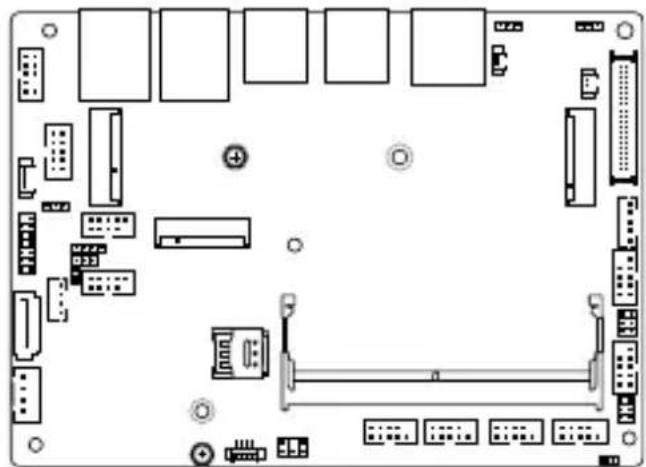
2.2 Single Board Computer layout
text_image
23 22 21 20 19 18 17 16 15 14 4 13 12 11 10 9 7 8 LAN_2 LAN_1 USB32G2_34 USB32G2_12 HDMI_DP1 VOC_PWR_SEL CLRTC VR_PROG BATTERY LVDS_EDP M_2_M LCO_BKLT_PANEL COM2 COM2_SEL1 COM1 COM1_SEL1 NANO_SIM_1 SODIMM_A1 COM_DEBUG COM4 COM3 COM6 COM5 INTRUDER DAC_PWR1 DC_PWR1 SATA_PWR SATA6G AT_ATX_SEL USB2_56 M_2_B M_2_E PWRBTN_EXTSW DIO SPI_TPM SMBUS DC NANO_SIM_1 CHA_FAN 3042 3062 4Jumpers Page
- Clear RTC RAM jumper 17
- Display Panel VCC Power Selection jumper 18
- COM Ring/+5V/+12V Selection jumper 18
- AT/ATX Mode Configuration jumper 19
| Connectors/slots Page | |
| 1. M.2 (E-key) Wi-Fi slot 20 | |
| 2. M.2 (B-key) slot 21 | |
| 3. Battery connector 22 | |
| 4. LVDS EDP Signal connector 22 | |
| 5. M.2 (M-key) slot 23 | |
| 6. Backlight Inverter Power connector 24 | |
| 7. Serial (COM) Port connector 25 | |
| 8. Chassis Intrusion connector 26 | |
| 9. DIMM slot 26 | |
| 10. COM Debug connector 27 | |
| 11. Nano SIM Card slot 27 | |
| 12. Chassis Fan connector | 28 |
| 13. USB 2.0 connector | 29 |
| 14. DC-in 4-Pin Power connector | 30 |
| 15. SATA 6Gb/s & SATA Power connector | 31 |
| 16. I2C connector | 32 |
| 17. SMBus connector | 32 |
| 18. SPI TPM connector | 33 |
| 19. GPIO connector 33 | |
| 20. Stereo Speaker connector | 34 |
| 21. Power Button connector | 34 |
| 22. Front Panel connector | 35 |
| 23. Front Panel Audio (Line Out / Mic) connector | 36 |
2.3 Onboard jumpers
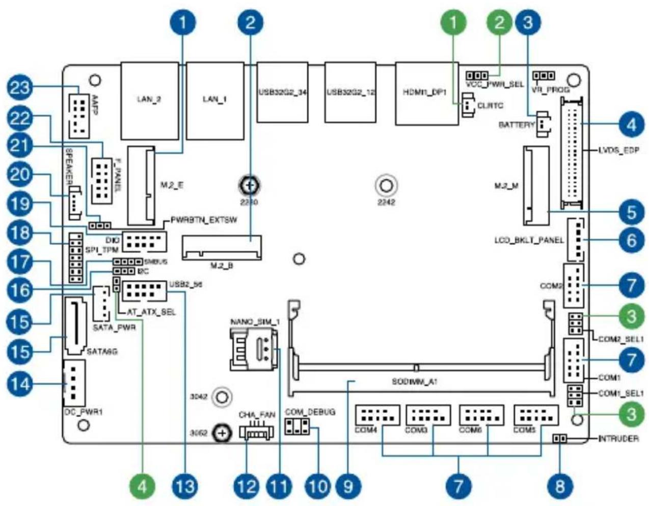
1. Clear RTC RAM jumper
The Clear RTC RAM jumper allows you to clear the Real Time Clock (RTC) RAM in the CMOS, which contains the date, time, system passwords, and system setup parameters.
text_image
CLRTC PIN 1To erase the RTC RAM:
- Turn OFF the computer and unplug the power cord.
- Short-circuit this jumper with a metal object or jumper cap for about 5-10 seconds.
- Plug the power cord and turn ON the computer.
- Hold down the
key during the boot process and enter BIOS setup to re-enter data.
NOTE: If the steps above do not help, remove the onboard button cell battery and short-circuit this jumper again to clear the CMOS RTC RAM data. After clearing the CMOS, reinstall the button cell battery.
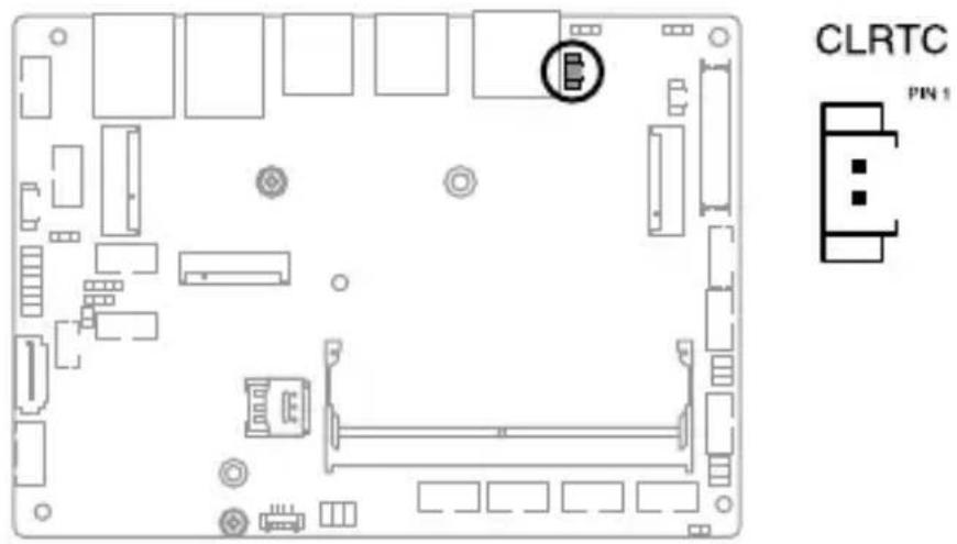
2. Display Panel VCC Power Selection jumper
The Display Panel VCC Power jumper allows you to select the voltage for the LVDS panel.
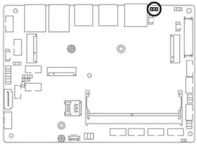
natural_image
Top-down schematic of a computer motherboard showing slots, connectors, and a highlighted component (no text or labels)VCC_PWR_SEL
+5V
+3V
(Default)
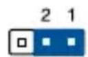
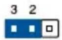
3. COM Ring/+5V/+12V Selection jumper
The COM Ring/+5V/+12V Selection jumper allows you to select the voltage for the COM port.
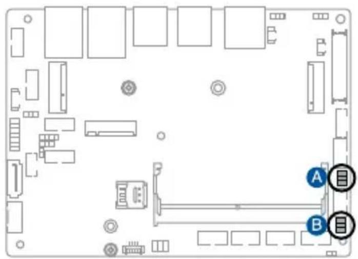
natural_image
Top-down schematic of a computer motherboard with labeled components (A and B) and connectors, no readable text or symbols beyond labels.
COM2_SEL

COM1_SEL
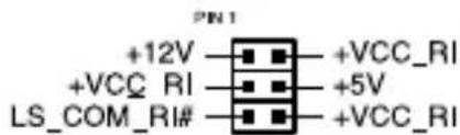
text_image
+12V +VCC_RI LS_COM_RI# +VCC_RI +5V +VCC_RI4. AT/ATX Mode Configuration jumper
The AT/ATX Mode Configuration jumper allows you to switch between AT or ATX modes. The default setting for this jumper is set to ATX mode with a jumper cap attached, to switch to AT mode, remove the jumper cap.
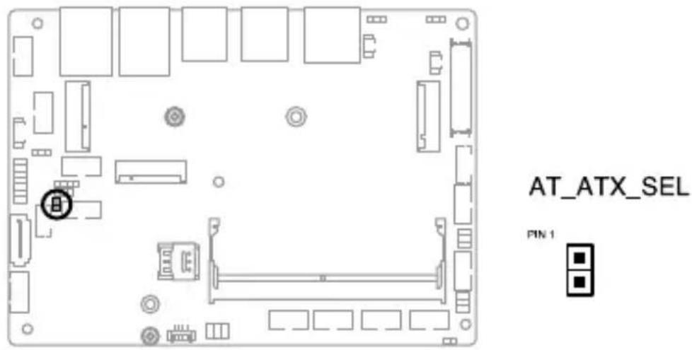
text_image
AT_ATX_SEL PIN 12.4 Internal slots and connectors
1. M.2 (E-key) Wi-Fi slot
The M.2 Wi-Fi slot allows you to install an M.2 Wi-Fi module (E-key, type 2230).
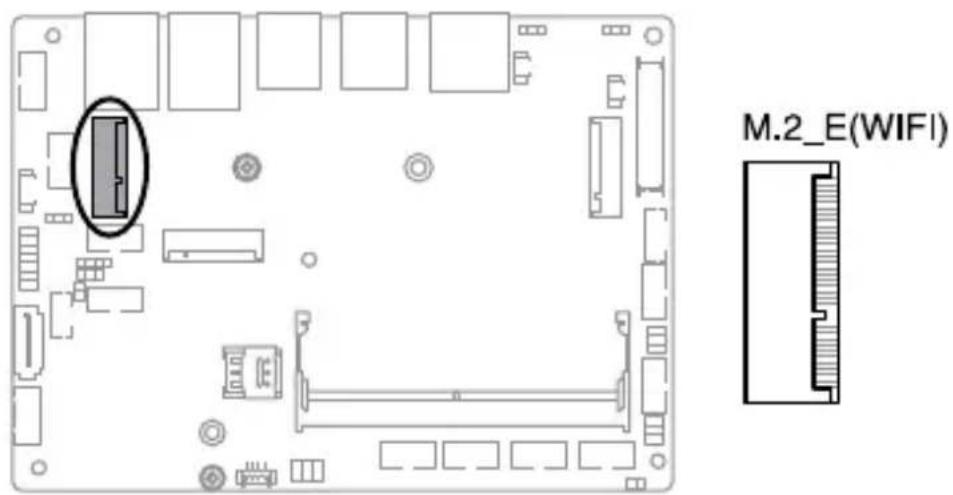
text_image
M.2_E(WIFI)NOTE:
• The M.2 Wi-Fi module is purchased separately.
• We recommend using a PH1 screwdriver with a torque of 2.0 ± 0.2 kgf-cm when tightening the screw.
2. M.2 (B-key) slot
The M.2 (B-key) slot allows you to install a B-key (PCIe/USB2.0/USB3.2 Gen 2) type 2242/3042/3052 M.2 device, such as a 4G LTE or 5G NR module.

text_image
M.2_BNOTE:
• The M.2 4G LTE or 5G NR module is purchased separately.
• We recommend using a PH1 screwdriver with a torque of 2.0 ± 0.2 kgf-cm when tightening the screw.
3. Battery connector
The Battery connector allows you to connect a lithium CMOS battery.
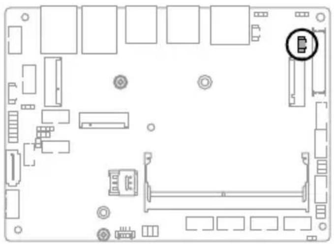
natural_image
Top-down schematic of a computer motherboard showing internal components and connectors (no text or labels)BATTERY

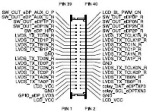
4. LVDS EDP Signal connector
The LVDS EDP Signal connector allows you to connect an internal embedded DisplayPort.
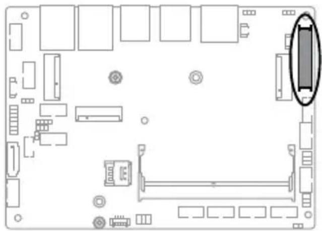
natural_image
Top-down schematic of a computer motherboard showing CPU socket, RAM slots, and memory compartment (no text or labels)LVDS_EDP
text_image
PIN 39 PIN 40 SW_OUT_eDP_AUX_C_P SW_OUT_eDP_AUX_C_N SW_OUT_eDP_TP_R SW_OUT_eDP1N_R SW_eDP_HPD LVDS_TX_TOIN_R LVDS_TX_TO1P_R LVDS_TX_TB1N_R LVDS_TX_TB1P_R GND LVDS_TX_TO2N_R LVDS_TX_TO0P_R LVDS_TX_TO2N_R LVDS_TX_TO0P_R LVDS_TX_TO2N_R LCD_VCC GPIO_eDP_LVDS LCD_VCC LCD_IL_PWM_CN SW_OUT_eDP6P_R SW_OUT_eDPON_R SW_OUT_eDP2N_R SW_OUT_eDP2P_R LVDS_TX_TCLKIN_R LVDS_TX_TCLKIP_R LVDS_TX_TCLKN_R LVDS_TX_TCLKP_R LVDS_TX_TBDN_R LVDS_TX_TB0P_R splay_DAT_eDPTXP3 splay_SCL_eDPTXN3 GND LCD_VCC PIN 1 PIN 2Connector type
WtoB CON 2x 20P G/F 1.25 BLK S/T SMT
ACES/50286-04071-001
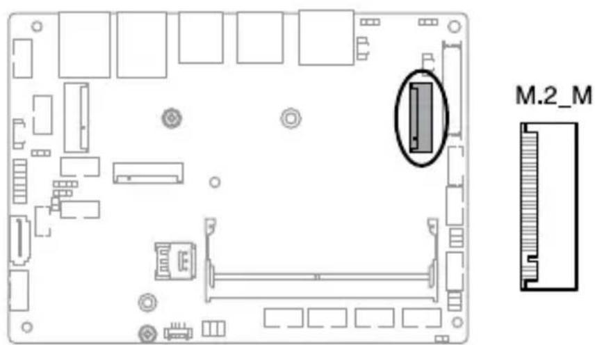
5. M.2 (M-key) slot
The M.2 slot allows you to install an M-key (SATA/PCIe) type 2242/2280 M.2 device, such as a M.2 SSD module.
text_image
M.2_MNOTE:
• The M.2 SSD module is purchased separately.
• We recommend using a PH1/sleeve screwdriver with a torque of 2.0 ± 0.2 kgf-cm when tightening the screw/standoff.
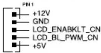
6. Backlight Inverter Power connector
The Backlight Inverter Power connector is for the panel back light module power input.

natural_image
Top-down schematic of a computer motherboard layout with no visible text or symbolsLCD_BKLT_PANEL
text_image
PIN1 +12V GND LCD_ENABKLT_CN LCD_BL_PWM_CN +5VConnector type
WAFER 5P 2.0mm pitch NATURAL S/T
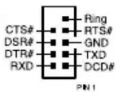
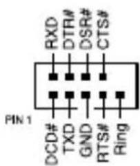
7. Serial (COM) Port connector
The Serial (COM) Port connector allows you to connect a serial port module. Connect the serial port module cable to this connector, then install the module to a slot opening on the system chassis.

text_image
Diagram of a computer motherboard with labeled components A, B, C, D, E, F and connectors
text_image
CTS# DSR# DTR# RXD Ring RTS# GND TXD DCD# PIN 1
text_image
RXD DTR# DSR# CTS# PIN 1 DCD# TXD GND RTS# RingConnector type
BOX header 2x5p, K10, 2.0mm pitch
NOTE:
- The serial port module is purchased separately.
• COM1 and COM2 support RS-232/422/485.
• COM3-COM6 support RS-232.
8. Chassis Intrusion connector
The Chassis Intrusion connector allows you to connect an intrusion sensor or microswitch for the chassis intrusion detection feature. When you remove any chassis component, the sensor or microswitch triggers and sends a high level signal and records a chassis intrusion event.
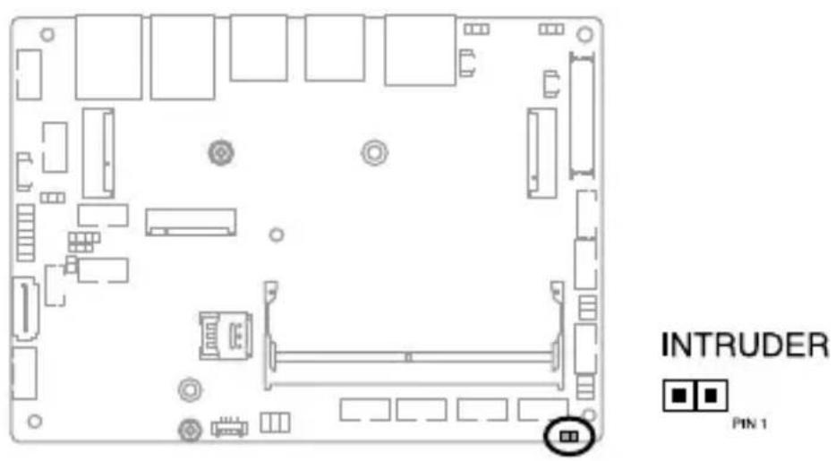
text_image
INTRUDER PIN 1NOTE: By default, a jumper cap that disables the intrusion detection feature is installed on the connector to prevent accidental triggers.
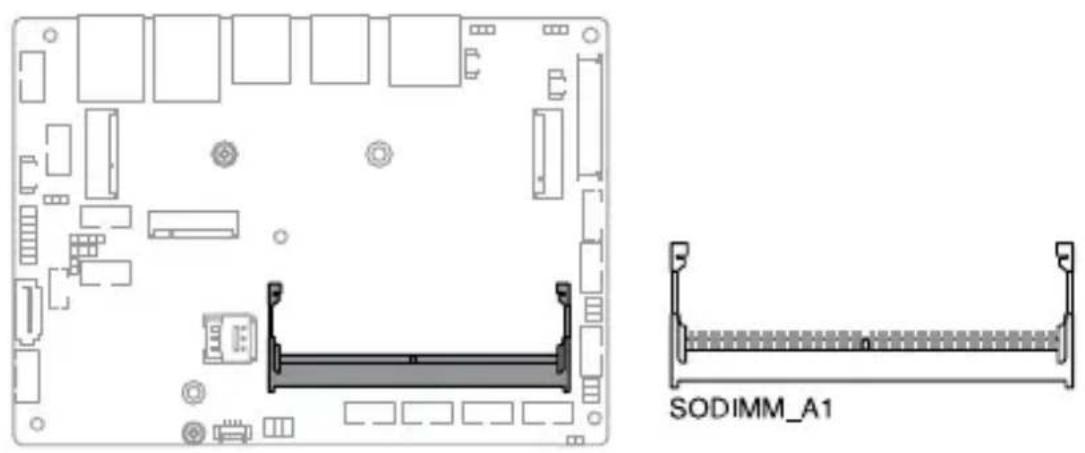
9. DIMM slot
The motherboard comes with a Small Outline Dual Inline Memory Module (SODIMM) slot designed for DDR5 (Double Data Rate 5) memory modules.
natural_image
Technical diagram of a computer motherboard layout with SODIMM_A1 component, showing internal components and mounting points (no text or symbols beyond labels)10. COM Debug connector
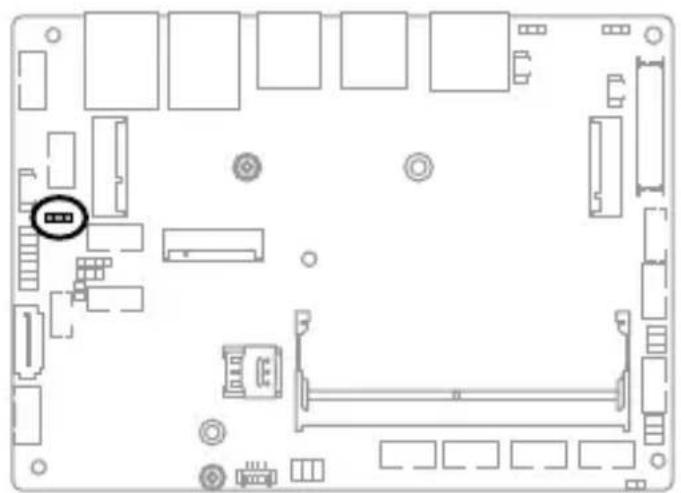
The COM Debug connector allows you to connect a COM debug card.

text_image
COM_DBG +3V O_COMDBG_P80 PIN 1 DEBUG_CONTROL GND GNDConnector type
Header 2x3p, 2.54mm pitch
11. Nano SIM Card slot
The Nano SIM Card slot allows you to install a Nano SIM card.
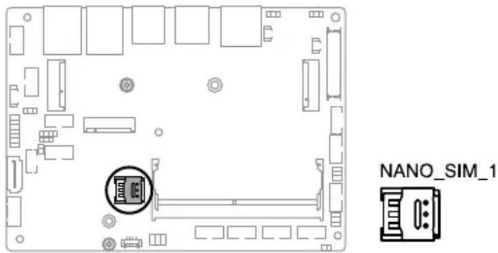
text_image
NANO_SIM_1NOTE: The Nano SIM card is purchased separately.
12. Chassis Fan connector
The Chassis Fan connector allows you to connect a fan to cool the system.
natural_image
Top-down schematic of a computer motherboard showing internal components and connectors (no text or labels)
text_image
CHA_FAN PIN 1 GND +12V O_CHAFANIN_R O_CHAFAN_PWM_QConnector type
WtoB CON 4P, 1.25mm, R/A
WARNING!
- DO NOT forget to connect the fan cable to the fan connector. Insufficient air flow inside the system may damage the Single Board Computer components. These are not jumpers! Do not place jumper caps on the fan connectors!
• Make sure that the cable is fully inserted into the connector.
13. USB 2.0 connector
The USB 2.0 connector allows you to connect a USB module for additional USB 2.0 ports. The USB 2.0 connector provides data transfer speeds of up to 480 MB/s connection speed.

natural_image
Top-down schematic of a computer motherboard layout with labeled components (no text or symbols)
text_image
USB2_56 +5V S_USB_PN4 S_USB_PP4 GND NC PN1 +5V S_USB_PN3 S_USB_PP3 GNDConnector type
BOX header 2x5p, K9, 2.0mm pitch
WARNING! DO NOT connect a 1394 cable to the USB connectors. Doing so will damage the Single Board Computer!
NOTE: The USB 2.0 module is purchased separately.
14. DC-in 4-Pin Power connector
The DC-in 4-pin Power connector is for DC power input. Using a compatible power cable, you may connect a suitable power supply with DC-in jacks.

Connector type
POWER CON 4P, S/T
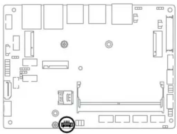
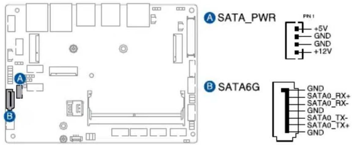
15. SATA 6Gb/s & SATA Power connector
The SATA 6Gb/s and SATA Power connectors allow you to connect SATA devices such as optical disc drives and hard disk drives via a SATA cable and power cable.
text_image
A SATA_PWR PN 1 +5V GND GND +12V B SATA6G GND SATA0_RX+ SATA0_RX- GND SATA0_TX- SATA0_TX+ GNDConnector type
Wafer HD 4P, 2.0mm pitch & Wafer HD 7p, 1.27mm pitch
NOTE: Ensure to use the bundled cable when connecting a storage device to this connector.
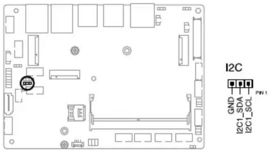
16. I2C connector
The I2C (Inter-Integrated Circuit) connector allows you to connect an I2C-compatible IoT security module.
text_image
I2C GND I2C1_SDA I2C1_SCL PIN 1Connector type
Header 1x3p, K3, 2.0mm pitch
17. SMBus connector
The System Management Bus (SMBus) connector allows you to connect SMBus devices. This connector is generally used for communication with system and power management-related tasks.

text_image
SMBUS GND SMBUS_ALERT# SMBUS_DATA SMBUS_CLK PN1Connector type
Header 1x4p, 2.0mm pitch
18. SPI TPM connector
The SPI TPM connector supports a Trusted Platform Module (TPM) system, which can securely store keys, digital certificates, passwords, and data. A TPM system also helps enhance network security, protects digital identities, and ensures platform integrity.

text_image
SPI_TPM T_SPI_MOSI T_SPI_CLK GND T_SPI_BIOS_WP# S_SPI_TPM_CS2# S_SPI_TPM_IRQ# T_SPI_HOLD# T_SPI_MISO S_SPI_CS0# +3VSB_SPI NC S_PLTRST# +VCC_SPI_TPM PIN1Connector type
Header 2x7p, K14, 2.0mm pitch
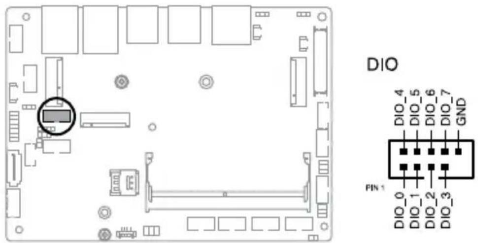
19. GPIO connector
The GPIO connector allows you to connect a general purpose input/output module to customize digital signal input/output.
text_image
DIO DIO_4 DIO_5 DIO_6 DIO_7 GND PIN 1 DIO_0 DIO_1 DIO_2 DIO_3Connector type
BOX header 2x5p, K9, 2.0mm pitch
20. Stereo Speaker connector
The Stereo Speaker connector allows you to connect the chassis-mounted system warning speaker. The speaker allows you to hear system beeps and warnings.
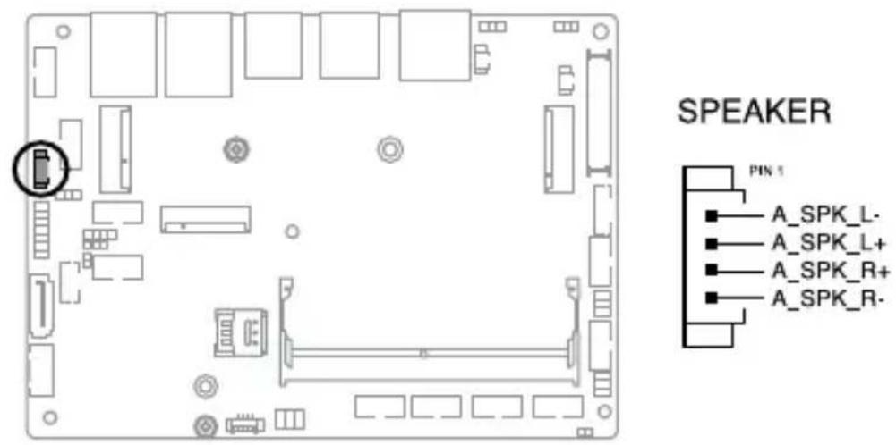
Connector type
WtoB CON 4P, 1.25mm, S/T
21. Power Button connector
The Power Button connector allows you to connect an external power button.
natural_image
Top-down schematic of a computer motherboard showing CPU socket, RAM slots, and connectors (no text or labels)
text_image
PWRBTN_EXTSW PN1 O_RSTCON# GND PWRBTN#22. Front Panel connector
The Front Panel connector supports several chassis-mounted functions.
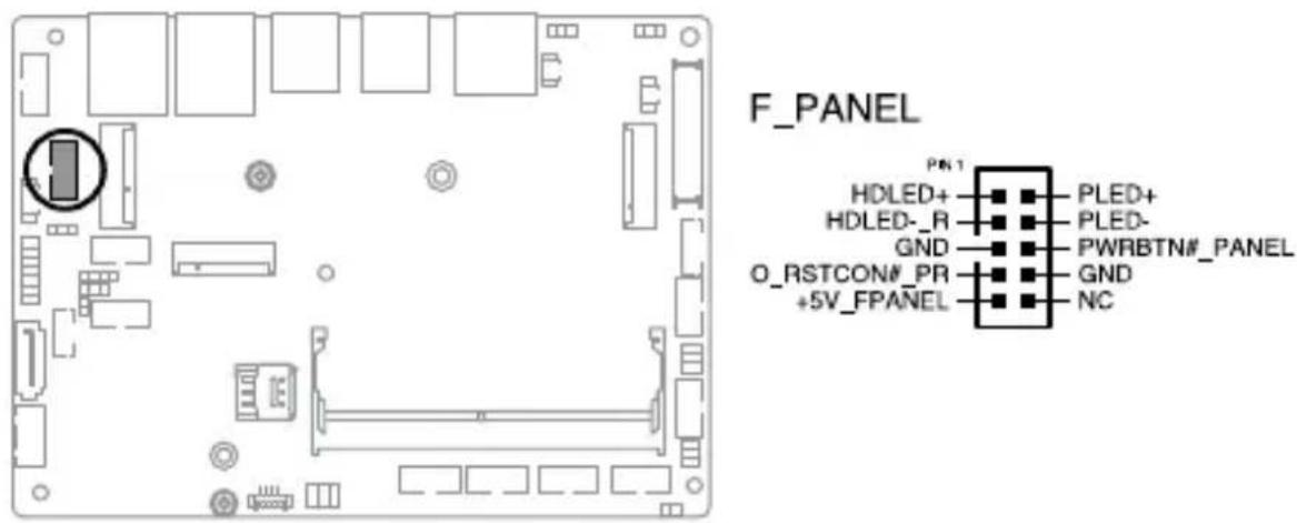
text_image
F_PANEL PEN1 HDLED+ HDLED- R GND O_RSTCON#_PR +5V_FPANEL PLED+ PLED- PWRBTN#_PANEL GND NCConnector type
BOX header 2x5p 2.0mm pitch
• System Power LED connector (PLED)
The 2-pin connector allow you to connect the System Power LED. The System Power LED lights up when the system is connected to a power source, or when you turn on the system power, and blinks when the system is in sleep mode.
• Storage Device Activity LED connector (HDLED)
The 2-pin connector allows you to connect the Storage Device Activity LED. The Storage Device Activity LED lights up or blinks when data is read from or written to the storage device or storage device add-on card.
• Power Button/Soft-off Button connector (PWRBTN)
The 3-1 pin connector allows you to connect the system power button. Press the power button to power up the system, or put the system into sleep or soft-off mode (depending on the operating system settings).
- Reset button connector (O\_RSTCON)
The 2-pin connector allows you to connect the chassis-mounted reset button. Press the reset button to reboot the system.
23. Front Panel Audio (Line Out / Mic) connector
The Front Panel Audio connector is for a line out /microphone module that supports HD Audio. Connect one end of the line Out / mic module cable to this connector.

natural_image
Top-down schematic of a computer motherboard showing internal components and connectors (no text or labels)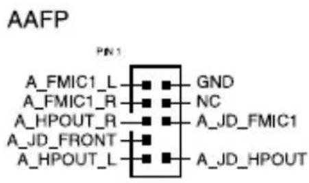
text_image
AAFP PN1 A_FMIC1_L ▪ GND A_FMIC1_R ▪ NC A_HPOUT_R ▪ A_JD_FMIC1 A_JD_FRONT ▪ A_HPOUT_L ▪ A_JD_HPOUTConnector type
BOX header 2x5p, K8, 2.0mm pitch
NOTE: We recommend that you connect a high-definition line out/mic module to this connector to avail of the Single Board Computer's high-definition audio capability.
2.5 I/O connectors
Front panel

text_image
1 2 3 4 5 6Front panel connectors
| 1. HDMI port |
| 2. DisplayPort |
| 3. USB 3.2 Gen 2 (10 Gbps) ports |
| 4. USB 3.2 Gen 1 (5 Gbps) ports |
| 5. LAN (RJ-45) 2.5 GbE port |
| 6. LAN (RJ-45) 1 GbE port |
3
Upgrading your Single Board Computer
IMPORTANT!
- Make sure that your hands are dry before proceeding with the rest of the installation process. Before installing any of the features in this guide, use a grounded wrist strap or touch a safely grounded object or metal object to avoid damaging them due to static electricity.
- Turn off the power of your Single Board Computer, and allow it to cool for at least 10 minutes before performing any installation/uninstallation process.
NOTE: The illustrations in this section are for reference only. The slots may vary depending on model.
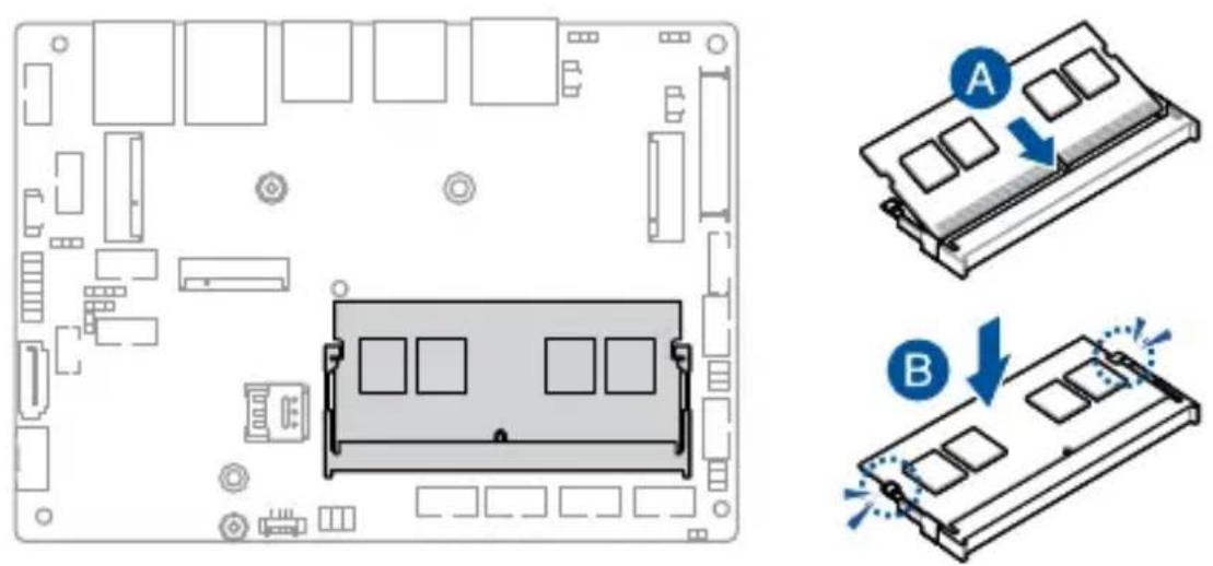
3.1 Installing memory modules
Your Single Board Computer comes with one (1) SO-DIMM memory slot that allows you to install DDR5 SO-DIMMs.
WARNING! Make sure to unplug the power supply before adding or removing DIMMs or other system components. Failure to do so may cause severe damage to both the Single Board Computer and its components.
Align and insert the memory module into the slot (A) and press it down (B) until it is securely seated in place.
3.2 Installing a 2.5" storage device
- Connect the storage device cable to the storage device.
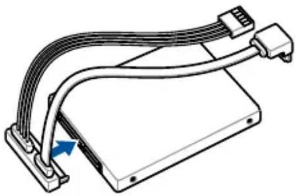
natural_image
Technical line drawing of a mechanical device with attached cables and connectors (no text or symbols)- Connect the storage device cable to the SATA6G and SATA_PWR connectors on the Single Board Computer.
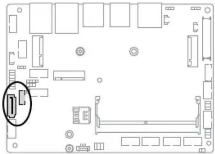
natural_image
Top-down schematic of a computer motherboard showing internal components and connectors (no text or labels)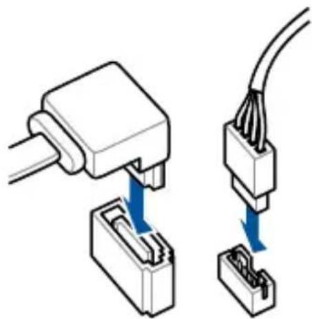
natural_image
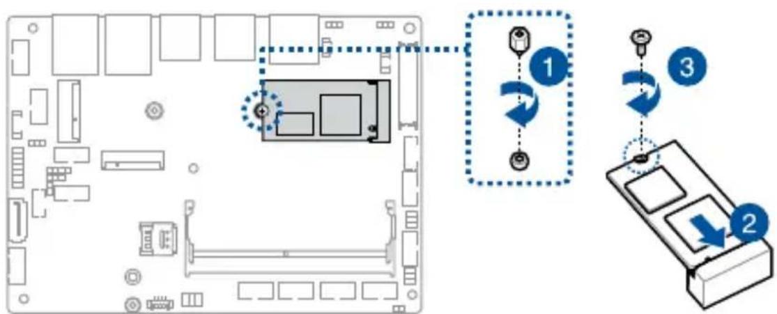
Diagram showing two connected electrical connectors with blue arrows indicating connection points (no text or symbols present)3.3 Installing an M.2 B-key module
Your Single Board Computer comes with an M.2 (B-key) slot that allows you to install a B-key (PCIe/USB2.0/USB3.2 Gen 2) type 2242/3042/3052 M.2 device, such as a 4G LTE or 5G NR module.
WARNING! RF modules are intended for OEM or host integrators only. For availability of system level RF certification, check with your OEM integrator.
To install a 4G LTE module:
- Remove the screw from the M.2 standoff.
- Align and insert the module into the slot.
- Press down, and then secure it in place using the screw previously removed.

natural_image
Top-down schematic of a computer motherboard layout showing CPU socket, RAM slots, and connectors (no text or labels)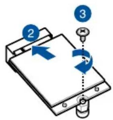
text_image
Diagram showing a device with labeled components and directional arrows, including numbered callouts 2, 3, and 4.NOTE: We recommend using a PH1 screwdriver with a torque of 2.0 ± 0.2 kgf-cm when tightening the screw.
- (Optional) Connect the RF cables from the antennas to your module. Make sure that the correct cable is attached to each of the connectors by following the illustration below.
NOTE:
- Connecting antennas to your module may strengthen the signal.
- A soft clicking sound indicates that the antenna has been securely attached on the module.
To install a 5G NR module:
-
Remove the screw from the M.2 standoff.
-
Align and insert the module into the slot.
-
Press down, and then secure it in place using the screw previously removed.
NOTE: We recommend using a PH1 screwdriver with a torque of 2.0 ± 0.2 kgf-cm when tightening the screw.

natural_image
Top-down schematic of a computer monitor layout with no text or symbols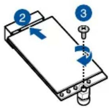
text_image
Diagram showing a device with labeled parts and directional arrows, including numbered indicators 2 and 3.- (Optional) Connect the RF cables from the antennas to your module. Make sure that the correct cable is attached to each of the connectors by following chart on the next page.
NOTE:
- Connecting antennas to your module may strengthen the signal.
- A soft clicking sound indicates that the antenna has been securely attached on the module.
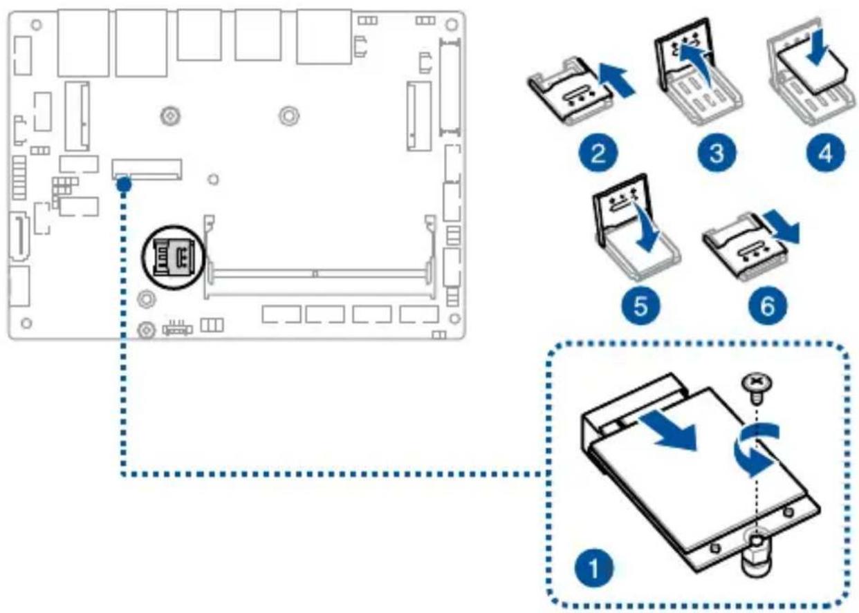
3.4 Installing a nano SIM card
- (Optional) Remove the 4G LTE or 5G NR module, if there is one installed, by first removing the screw securing the module, then removing the module.
- Push the nano SIM cover in the direction away from the DIMM slot.
- Lift the nano SIM cover.
- Place the nano SIM into the nano SIM slot.
- Replace the nano SIM cover.
- Push the nano SIM cover in the direction towards the DIMM slot to secure the nano SIM card.
flowchart
graph TD
    A["Device Layout"] --> B["Placement"]
    B --> C["File Transfer"]
    C --> D["File Setup"]
    D --> E["Assembly"]
    E --> F["Back Forward"]
    style A fill:#f9f,stroke:#333
    style B fill:#ccf,stroke:#333
    style C fill:#cfc,stroke:#333
    style D fill:#fcc,stroke:#333
    style E fill:#cff,stroke:#333
    style F fill:#ffc,stroke:#333
3.5 Installing a wireless card
-
Remove the screw from the M.2 standoff.
-
Align and insert the wireless card into its slot on the Single Board Computer.
-
Gently push down the wireless card on top of the standoff, and then fasten it using the previously removed screw.
NOTE: We recommend using a PH1 screwdriver with a torque of 2.0 ± 0.2 kgf-cm when tightening the screw.
- (Optional) Connect the antennas to your wireless card.
NOTE:
- Connecting antennas to your wireless card may strengthen the wireless signal.
- A soft clicking sound indicates that the antenna has been securely attached on the wireless card.
• The antennas are purchased separately.
natural_image
Top-down schematic of a computer motherboard layout showing CPU socket, RAM slots, and connectors (no text or labels)
text_image
Diagram showing a device with labeled components and directional arrows, likely illustrating a mechanical or digital process.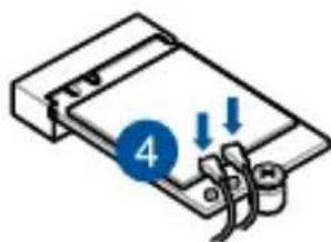
natural_image
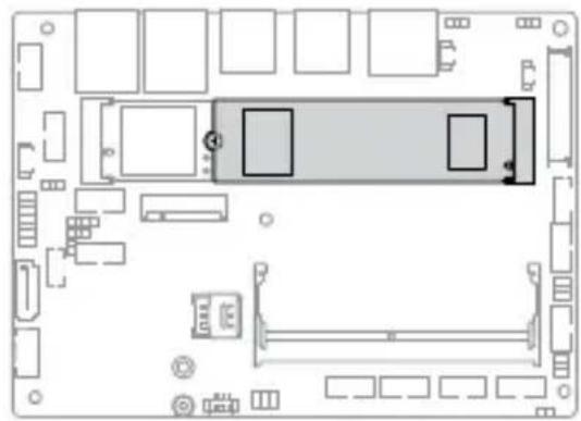
Diagram of a mechanical device with a blue circular indicator labeled '4' and downward arrows, no readable text or symbols present.3.6 Installing an M.2 SSD
To install an M.2 2242 SSD:
- (Optional) Replace the standoff if it was removed.
NOTE: We recommend using a PH1/sleeve screwdriver with a torque of 2.0 ± 0.2 kgf-cm when tightening the standoff.
-
Align and insert the M.2 SSD into its slot inside the Single Board Computer.
-
Gently push down the M.2 SSD on top of the standoff and fasten it using a screw.
NOTE: We recommend using a PH1 screwdriver with a torque of 2.0 ± 0.2 kgf-cm when tightening the screw.
text_image
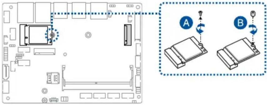
Diagram showing a computer motherboard with labeled components and directional arrows indicating motion or movement.To install an M.2 2280 SSD:
- (Optional) If a wireless card is installed, remove the screw holding it in place (A), replace it with a standoff (B), and skip to step 3.
text_image
Diagram showing a computer motherboard layout with labeled components and two connected devices labeled A and B, indicating data transfer or synchronization.NOTE: We recommend using a PH1/sleeve screwdriver with a torque of 2.0 ± 0.2 kgf-cm when tightening the standoff.
- (Optional) Replace the standoff if it was removed.
NOTE: We recommend using a PH1/sleeve screwdriver with a torque of 2.0 ± 0.2 kgf-cm when tightening the standoff.
-
Align and insert the M.2 SSD into its slot inside the Single Board Computer.
-
Gently push down the M.2 SSD on top of the standoff and fasten it using a screw.
NOTE: We recommend using a PH1 screwdriver with a torque of 2.0 ± 0.2 kgf-cm when tightening the screw.
natural_image
Top-down schematic of a computer room layout with monitor, keyboard, and mouse (no text or labels)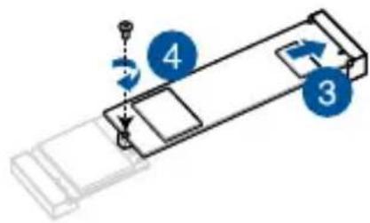
flowchart
graph TD
    A["Start"] --> B{Step 1}
    B -->|Yes| C["Step 2"]
    B -->|No| D["Step 3"]
    C --> E["Step 4"]
    D --> F["End"]
3.7 Installing a heatsink
-
Place the heatsink with its fins faced down on a flat surface.
-
Place the Single Board Computer over the heatsink so that the five (5) screw holes on the Single Board Computer are aligned to the five (5) standoffs on the heatsink as shown below.
-
Secure the Single Board Computer to the heatsink using the five (5) spring screws bundled with the heatsink in the sequence shown below.
text_image
Diagram of an electronic device with labeled components A, B, C, D, and E, showing internal structure and connections.- (Optional) Attach the heatsink and Single Board Computer assembly to your chassis using the M3 mounting holes along the four sides of the heatsink together with the bundled M3 screws.
NOTE: A total of twelve (12) mounting holes are provided for more flexibility in attaching the assembly to your chassis.

text_image
M3 mounting holes
text_image
M3 Screw Dimensions PHILLIPS#1 D (5.30-5.60) P0.5 NYLOK d (2.88-2.98) H (0.90-1.00) L (6.70-7.00)3.8 Installing a heat spreader
- Place the heat spreader with its copper pad and thermal interface material facing up on a flat surface.
- Remove the plastic protective film from the copper pad and thermal interface material on the heat spreader, if there is one.
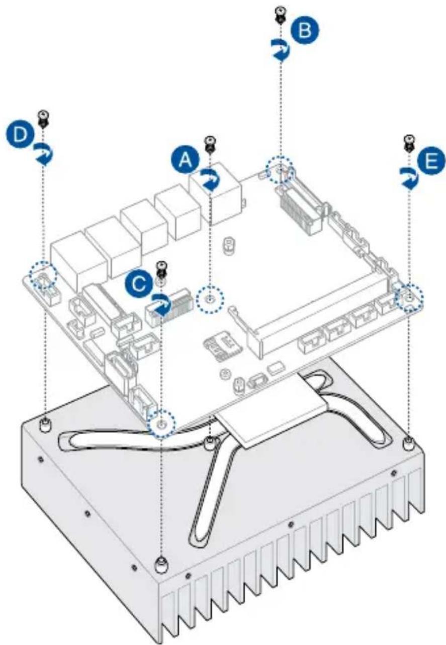
- Orient the Single Board Computer so that the CPU and chipset on its backside are in direct contact with the copper pad on the heat spreader, and the five (5) screw holes on the Single Board Computer are aligned to the five (5) standoffs on the heat spreader.

text_image
Copper pad & thermal interface material Screw hole Standoff- Secure the Single Board Computer to the heat spreader using the five (5) M2.5 spring screws bundled with the heat spreader in the sequence shown below.

text_image
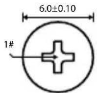
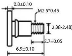
M2.5 spring screw A B C D EM2.5 Spring Screw Dimensions
text_image
0.8±0.10 M2.5*0.45 2.38-2.48) 2.7±0.05 6.9±0.10
text_image
2.90±0.05 4.8±0.2 6.0±0.10 0.45±0.03
- Mount the Single Board Computer and heat spreader assembly to the chassis using four (4) M2.5 screws to the four (4) chassis mounting screw holes on the heat spreader. Refer to the illustration below for the location of the chassis mounting screw holes.

text_image
Chassis mounting screw holeBIOS Setup
4
4.1 Getting to know your BIOS
The BIOS (Basic Input and Output System) stores system hardware settings such as Storage Device Configuration, Advanced Power Management, and Boot Device Configuration that are needed for system startup. Under normal circumstances, the default BIOS settings apply to most conditions to ensure optimal performance. DO NOT change the default BIOS settings except in the following circumstances:
- An error message appears on the screen during the system bootup and requests you to run the BIOS setup.
- You have installed a new system component that requires further BIOS settings or update.
WARNING! Inappropriate BIOS settings may result to instability or boot failure. We strongly recommend that you change the BIOS settings only with the help of a trained service personnel.
NOTE:
- The BIOS setup screens shown in this section are for reference purposes only, and may not exactly match what you see on your screen.
- BIOS settings and options may vary due to different BIOS release versions. Please refer to the latest BIOS version for settings and options.
4.2 BIOS setup program
Use the BIOS Setup program to update the BIOS or configure its parameters. The BIOS screens include navigation keys and brief online help to guide you in using the BIOS Setup program.
Entering BIOS Setup at startup
To enter BIOS Setup at startup:
- Press
Entering BIOS Setup after POST
To enter BIOS Setup after POST:
- Press
- Press the power button to turn the system off then back on. Do this option only if you failed to enter BIOS Setup using the first option.
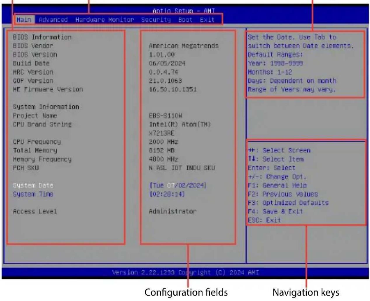
BIOS menu screen
This section provides a brief introduction of the BIOS Interface of your Single Board Computer.
Menu items
General helpMenu bar
text_image
Antio Setup - AHT Main Advanced Hardware Monitor Security Boot Exit BIOS Information BIOS Vendor BIOS Version Build Date HRC Version GOP Version ME Firmware Version System Information Project Name CPU Brand String CPU Frequency Total Memory Memory Frequency PCR SKU System Date System Time Access Level American Megatrends 1.01.00 06/05/2024 0.0.4.74 21.0.1063 16.50.10.1351 EBS-S110W Intel(R) Atom(TM) X7213BE 2000 MHz 8192 MB 4800 MHz N ASL IOT INDU SKU [Tue 07/02/2024] [02:28:14] Administrator Set the Date, Use Tab to switch between Date elements. Default Ranges: Year: 1598-9999 Months: 1-12 Days: Dependent on month Range of Years may vary. ++: Select Screen T↓: Select Item Enter: Select +/-: Change Opt. F1: General Help F2: Previous Values F3: Optimized Defaults F4: Save & Exit ESC: Exit Version 2.22.1293 Copyright (C) 2024 AMI Configuration fields Navigation keysMenu bar
The menu bar on top of the screen has the following main items:
| Main For changing the basic system configuration | |
| Advanced For changing advanced system settings | |
| Hardware Monitor | For viewing system temperature/power status and changing the fan mode |
| Security For changing security settings | |
| Boot For changing system boot configuration | |
| Exit For selecting save and exit options or loading default settings | |
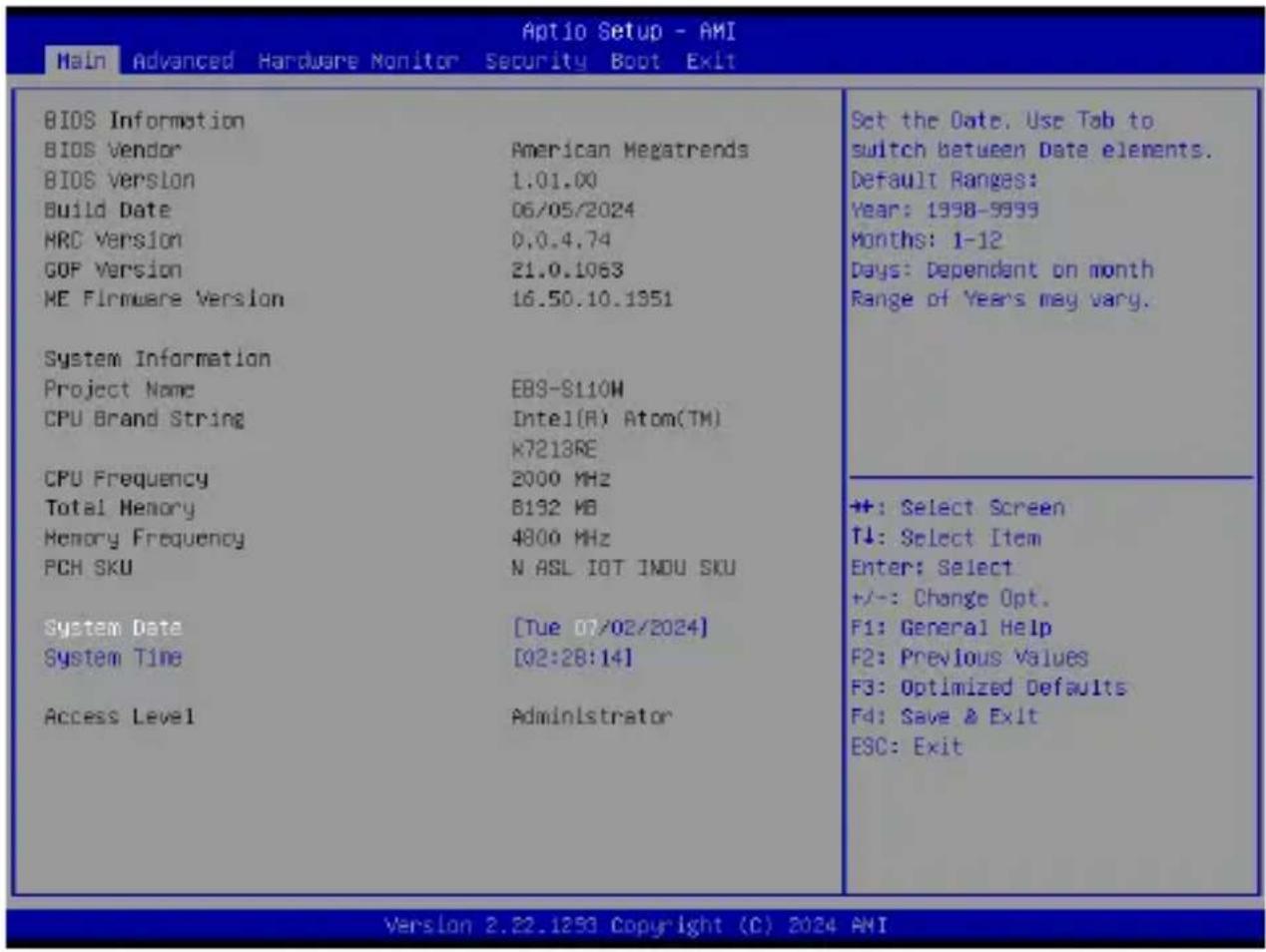
4.3 Main Menu
When you enter the BIOS Setup program, the Main menu screen appears. The Main menu provides you an overview of the basic system information, and allows you to set the system date and time. Scroll down to display the other BIOS items.
text_image
Main Advanced Hardware Monitor Security Boot Exit BIOS Information BIOS Vendor American Megatrends BIOS Version 1.01.00 Build Date 06/05/2024 HRC Version 0.0.4.74 GOP Version 21.0.1063 ME Firmware Version 16.50.10.1951 System Information Project Name EBS-S110W CPU Brand String Intel(R) Atom(TM) K7213RE CPU Frequency 2000 MHz Total Memory B192 MB Memory Frequency 4800 MHz PCH SKU N ASL IOT INDU SKU System Date [Tue 07/02/2024] System Time [02:28:14] Access Level Administrator Set the Date. Use Tab to switch between Date elements. Default Ranges: Year: 1998-9999 Months: 1-12 Days: Dependent on month Range of Years may vary. +: Select Screen T↓: Select Item Enter: Select +/-: Change Opt. F1: General Help F2: Previous Values F3: Optimized Defaults F4: Save & Exit ESC: Exit Version 2.22.1293 Copyright (C) 2024 AMISystem Date [Day mm/dd/yyyy]
Allows you to set the system date.
System Time [hh:mm:ss]
Allows you to set the system time.
4.4 Advanced menu
The Advanced menu items allow you to change the settings for the CPU and other system devices.
WARNING! Be cautious when changing the settings of the Advanced menu items. Incorrect field values can cause the system to malfunction.
| LVDS Configuration PCB-FW Configuration Trusted Computing CPU Configuration Graphics Configuration Super ID Configuration Serial Console Redirection SATA Configuration Network Stack Configuration USB Configuration NVMe Configuration Onboard Devices Configuration APM Configuration EZ-Flash Hatchdog Timer | LVDS Configuration |
| ++: Select Screen T↓: Select Item Enter: Select +/-: Change Opt. F1: General Help F2: Previous Values F3: Optimized Defaults F4: Save & Exit ESC: Exit |
4.4.1 LVDS Configuration

text_image
Aptio Setup - AMI Advanced LVDS Configuration Switch to LVDS [Disabled] Disable or Enable Switch to LVDSSwitch to LVDS
Allows you to enable or disable Switch to LVDS.
Configuration options: [Disable] [Enable]
NOTE: The following item appears when you set Switch to LVDS to [Enabled].
All-in-One Chassis
Allows you to select All-in-One (AiO) chassis (if applicable) for simplified AiO configuration.
Configuration options: [None] [1920*1080 LVDS1] [1920*1080 LVDS2] [1920*1080 LVDS3] [1600*900 LVDS4]
NOTE:
- Be cautious when selecting AiO chassis. Incorrect selection of AiO chassis can cause incorrect operation or potential damage to AiO chassis hardware.
- The following items appear only when you set All-in-One Chassis to [None].
EDID Data Source
Configuration options: [Pre-defined] [Flat Panel Display]
NOTE: The following item appears when you set EDID Data Source to [Pre-defined].
LFP Panel Type
Allows you to select LFP panel used by Internal Graphics Device.
Configuration options: [VBIOS Default] [640x480] [800x600] [1024x768]
[1280x1024] [1400x1050 LVDS1] [1400x1050 LVDS2] [1600x1200] [1366x768]
[1680x1050] [1920x1200] [1440x900] [1600x900] [1024x768] [1280x800]
[1920x1080] [2048x1536]
Inverter Polarity
Allows you to set the inverter board polarity.
Configuration options: [Inverted] [Normal]
NOTE:
• Normal: PWM = 0% (Dim)
Inverted: PWM = 0% (Bright)
- Consult inverter board specifications for proper value.
Channel Select
Configuration options: [Dual Channel] [Single Channel]
Mode Select
Configuration options: [JEIDA] [VESA 6bit] [VESA 8bit] [VESA 10bit]
DIGON enable to LVDS\_ON enable(T2)
Use the <+> or <-> to adjust the value. The values range from 0 to 50.
LVDS\_ON enable to BLON enable (T3)
Use the <+> or <-> to adjust the value. The values range from 0 to 1023.
BLON disable to LVDS\_ON disable (T4)
Use the <+> or <-> to adjust the value. The values range from 0 to 1023.
LVDS\_ON disable to DIGON disbale (T5)
Use the <+> or <-> to adjust the value. The values range from 0 to 50.
Completion of power down to power up (T7)
Use the <+> or <-> to adjust the value. The values range from 0 to 1023.
VARY\_BL enable to BL\_EN enable (T9)
Use the <+> or <-> to adjust the value. The values range from 0 to 1023.
BL\_EN enable to enable VARY\_BL disable (T10)
Use the <+> or <-> to adjust the value. The values range from 0 to 1023.
4.4.2 PCH-FW Configuration
The items in this menu allow you to configure Management Engine Technology Parameters.

text_image
Aptio Setup - AMI Advanced TPM Device Selection [dTPM] Selects TPM device: PTT or dTPM, PTT - Enables PTT inTPM Device Selection
This item allows you to select the TPM device.
[dTPM] Discrete TPM
[PTT] Intel Platform Trust Technology firmware TPM
NOTE:
- When [dTPM] is selected, PTT (firmware TPM) will be disabled, and the TPM device connected to the SPI TPM connector on the Single Board Computer will be enabled. If no TPM device is connected, the TPM feature will be disabled.
- When [PTT] is selected, PTT (firmware TPM) is enabled.
WARNING! When [dTPM] is selected, PTT (firmware TPM) will be disabled and all data saved on it will be lost.
4.4.3 Trusted Computing

text_image
Aptio Setup - AMI Advanced Configuration Security Device Support [Enable] NO Security Device Found Enables or Disables BIOS support for security device. 0.S. will not show SecurityNOTE: Changes here do not take effect until computer is restarted.
Security Device Support
Allows you to enable or disable the BIOS support for security device.
Configuration options: [Disable] [Enable]
NOTE: The following items appear when a TPM device is installed on your Single Board Computer.
SHA-1 PCR Bank
Configuration options: [Disabled] [Enabled]
SHA256 PCR Bank
Configuration options: [Disabled] [Enabled]
SHA384 PCR Bank
Configuration options: [Disabled] [Enabled]
Pending operation
Allows you to schedule an operation for security device.
Configuration options: [None] [TPM Clear]
NOTE: Your computer will reboot during restart in order to change the state of security device.
Platform Hierarchy
Configuration options: [Disabled] [Enabled]
Storage Hierarchy
Configuration options: [Disabled] [Enabled]
Endorsement Hierarchy
Configuration options: [Disabled] [Enabled]
4.4.4 CPU Configuration
The items in this menu show the CPU-related information that the BIOS automatically detects. Scroll down to display other BIOS items.
| CPU Configuration Type Intel(R) Atom(TM) x7213RE x806EO 0x806EO hardware capabilities provided by Vanderpool Technology. | When enabled, a VMH can utilize the additional | |
| ID | ||
| Efficient-core Information | ||
| L1 Data Cache | 32 KB x 2 | |
| L1 Instruction Cache | 64 KB x 2 | |
| L2 Cache | 2048 KB | |
| L3 Cache | 6 MB | |
| Performance-core Information | ||
| L1 Data Cache | N/A | **: Select Screen |
| L1 Instruction Cache | N/A | T1: Select Item |
| L2 Cache | N/A | Enter: Select +/-: Change Opt. |
| L3 Cache | N/A | |
| VMX | Supported | F1: General Help |
| SMX/TXT | Not Supported | F2: Previous Values F3: Optimized Defaults |
| Intel (VMK) Virtualization Technology | [Enabled] | F4: Save & Exit |
| VT-d | [Enabled] | ESC: Exit |
| CPU - Power Management Control | ||
Intel (VMX) Virtualization Technology
When set to [Enabled], a VMM can utilize the additional hardware capabilities provided by Vanderpool Technology.
Configuration options: [Disabled] [Enabled]
VT-d
Allows you to enable or disable VT-d capability.
Configuration options: [Disabled] [Enabled]
CPU - Power Management Control
Intel(R) SpeedStep(tm)
Allows more than two frequency to be supported.
Configuration options: [Disabled] [Enabled]
Intel(R) Speed Shift Technology
Allows you to enable or disable Intel(R) Speed Shift Technology support. When enabled, CPPC v2 interface allows hardware controlled P-states.
Configuration options: [Disabled] [Enabled]
Turbo Mode
Allows you to enable or disable processor Turbo Mode (requires Intel Speed Step or Intel Speed Shift to be available when enabled).
Configuration options: [Disabled] [Enabled]
C states
Allows you to enable or disable CPU Power Management. Allows CPU to go to C states when it's not 100% utilized.
Configuration options: [Disabled] [Enabled]
NOTE: The following item appears only when C states is set to [Enabled].
Enhanced C-States
Allows you to enable or disable C1E. When enabled, CPU will switch to minimum speed when all cores enter C-State.
Configuration options: [Disabled] [Enabled]
Power Limit 1 Override
Allows you to enable or disable Power Limit 1 override. If this option is disabled, BIOS will program the default values for Power Limit 1 and Power Limit 1 Time Window.
Power Limit 2 Override
Allows you to enable or disable Power Limit 2 override. If this option is disabled, BIOS will program the default values for Power Limit 2.
Power Limit 2
Allows you to configure Power Limit 2 value in milliwatts (e.g., enter 12500 for 12.5 W).
4.4.5 Graphics Configuration
The items in this menu allow you to configure settings related to graphics.

text_image
AptLo Setup - AMI Advanced Graphics Configuration RC6(Render Standby) [Enabled] Check to enable render standby support.RC6(Render Standby)
Allows you to enable or disable render standby support. Configuration options: [Disabled] [Enabled]
4.4.6 Super IO Configuration
The items in this menu allow you to configure system super IO chip parameters.

text_image
Aptio Setup - AMI Advanced Super IO Chip NCT8126D ► Serial Port 1 Configuration ► Serial Port 2 Configuration ► Serial Port 3 Configuration ► Serial Port 4 Configuration ► Serial Port 5 Configuration ► Serial Port 6 Configuration Set Parameters of Serial Port 1 (COMA)Super IO Chip
Serial Port 1-2 Configuration
Allows you to set the parameters of Serial Port 1-2.
Serial Port
Allows you to enable or disable Serial Port.
Configuration options: [Disabled] [Enabled]
NOTE: The following items appear only when Serial Port is set to [Enabled].
COM1-2 Control
Configuration options: [RS232] [RS422] [RS485]
Serial Port 3-6 Configuration
Allows you to set the parameters of Serial Port 3-6.
Serial Port
Allows you to enable or disable Serial Port.
Configuration options: [Disabled] [Enabled]
4.4.7 Serial Console Redirection
The items in this menu allow you to configure serial console redirection parameters.
| Aptio Setup - ANI Advanced | |
| COM1 Console Redirection 1 [Disabled] | Console Redirection Enable or Disable. |
| Console Redirection Settings | |
| COM2 Console Redirection 2 [Disabled] | |
| Console Redirection Settings | |
| COM3 Console Redirection 3 [Disabled] | |
| Console Redirection Settings | |
| COM4 Console Redirection 4 [Disabled] | +#: Select Screen T#: Select Item Enter: Select +/-: Change Opt. F1: General Help F2: Previous Values F3: Optimized Defaults F4: Save & Exit ESC: Exit |
| Console Redirection Settings | |
| COM5 Console Redirection 5 [Disabled] | |
| Console Redirection Settings | |
| COM6 Console Redirection 6 [Disabled] | |
| Console Redirection Settings | |
COM1-6
Console Redirection
Allows you to enable or disable the console redirection feature. Configuration options: [Disabled] [Enabled]
NOTE: The following item appears only when Console Redirection is set to [Enabled].
Console Redirection Settings
This item becomes configurable only when you enable the Console Redirection item. The settings specify how the host computer and the remote computer (which the user is using) will exchange data. Both computers should have the same or compatible settings.
Terminal Type
Allows you to set the terminal type.
[VT100] ASCII char set.
[VT100Plus] Extends VT100 to support color, function keys, etc.
[VT-UTF8] Uses UTF8 encoding to map Unicode chars onto 1 or more bytes.
[ANSI] Extended ASCII char set.
Bits per second
Selects serial port transmission speed. The speed must be matched on the other side. Long or noisy lines may require lower speeds.
Configuration options: [9600] [19200] [38400] [57600] [115200]
Data Bits
Configuration options: [7] [8]
Parity
A parity bit can be sent with the data bits to detect some transmission errors. [Mark] and [Space] parity do not allow for error detection.
[None] None.
[Even] parity bit is 0 if the num of 1's in the data bits is even.
[Odd] parity bit is 0 if num of 1's in the data bits is odd.
[Mark] parity bit is always 1.
[Space] parity bit is always 0.
Stop Bits
Stop bits indicate the end of a serial data packet. (A start bit indicates the beginning.) The standard setting is 1 stop bit. Communication with slow devices may require more than 1 stop bit.
Configuration options: [1] [2]
Flow Control
Flow control can prevent data loss from buffer overflow. When sending data, if the receiving buffers are full, a “stop” signal can be sent to stop the data flow. Once the buffers are empty, a “start” signal can be sent to re-start the flow. Hardware flow control uses two wires to send start/stop signals.
Configuration options: [None] [Hardware RTS/CTS]
VT-UTF8 Combo Key Support
Allows you to enable the VT-UTF8 Combo Key Support for ANSI/VT100 terminals.
Configuration options: [Disabled] [Enabled]
Recorder Mode
With this mode enabled only text will be sent. This is to capture Terminal data.
Configuration options: [Disabled] [Enabled]
Resolution 100x31
Allows you to enable or disable extended terminal resolution.
Configuration options: [Disabled] [Enabled]
Putty KeyPad
Allows you to select the FunctionKey and Keypad on Putty.
Configuration options: [VT100] [LINUX] [XTERMR6] [SCO] [ESCN] [VT400]
4.4.8 SATA Configuration
The items in this menu allow you to configure SATA device options.
While entering Setup, the BIOS automatically detects the presence of SATA devices. The SATA Port items show [Empty] if no SATA device is installed to the corresponding SATA port.
| Aptio Setup - AMI | |
| Advanced | |
| SATA Configuration | Enable/Disable SATA Device. |
| SATA Controller(s) [Enabled] | |
| SATA Mode Selection [AHCI] | |
| M.2_N SATA Empty | |
| M.2_N(SATA) [Enabled] | |
| SATA Empty | |
| SATA [Enabled] | |
SATA Controller(s)
Allows you to enable or disable the SATA Controller.
Configuration options: [Enabled] [Disabled]
NOTE: The following items appear only when SATA Controller(s) is set to [Enabled].
M.2\_M SATA
Allows you to enable or disable the SATA port. Configuration options: [Disabled] [Enabled]
SATA
Allows you to enable or disable the SATA port. Configuration options: [Disabled] [Enabled]
4.4.9 Network Stack Configuration
Allows you to configure network stack settings.

text_image
Aptio Setup - AMI Advanced Network Stack [Disabled] Enable/Disable UEFI Network StackNetwork Stack
Allows you to enable or disable UEFI Network Stack.
Configuration options: [Disabled] [Enabled]
NOTE: The following items appear only when Network Stack is set to [Enabled].
IPv4 PXE Support
Enables or disables the IPv4 PXE Boot Support. If disabled, IPv4 PXE boot option will not be created.
Configuration options: [Disabled] [Enabled]
IPv6 PXE Support
Enables or disables the IPv6 PXE Boot Support. If disabled, IPv6 PXE boot option will not be created.
Configuration options: [Disabled] [Enabled]
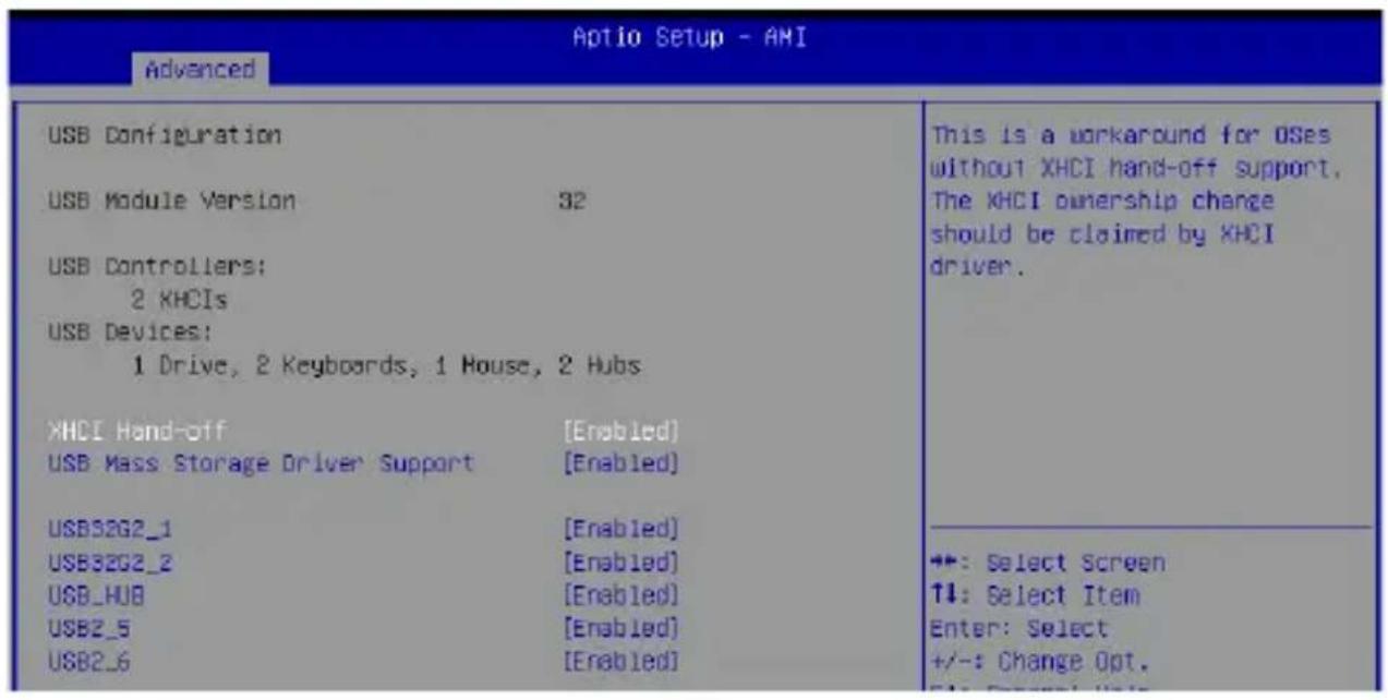
4.4.10 USB Configuration
text_image
Aptio Setup - AMI Advanced USB Configuration USB Module Version 32 USB Controllers: 2 KHCIs USB Devices: 1 Drive, 2 Keyboards, 1 House, 2 Hubs XHCI Hand-off [Enabled] USB Mass Storage Driver Support [Enabled] USB32G2_1 [Enabled] USB32G2_2 [Enabled] USB_HUB [Enabled] USB2_5 [Enabled] USB2_6 [Enabled] This is a workaround for OSes without XHCI hand-off support. The XHCI ownership change should be claimed by XHCI driver. ++: Select Screen ↑↓: Select Item Enter: Select +/-: Change Opt. File: Newark FilesNOTE: The USB Devices item shows the auto-detected values. If no USB device is detected, the item shows None.
XHCI Hand-off
NOTE: This item is set to [Disabled] by default for the EHCI (enhanced host controller interface) support by XHCI drivers in operating systems.
[Enabled] Support XHCI by BIOS for operating systems without XHCI support.
[Disabled] Support XHCI by XHCI drivers for operating systems with XHCI support.
USB Mass Storage Driver Support
Allows you to enable or disable the USB Mass Storage driver support. Configuration options: [Disabled] [Enabled]
USB32G2\_1-2
Allows you to enable or disable each USB port. When set to [Disabled], any USB devices plugged into the connector will not be detected by the BIOS or OS.
Configuration options: [Disabled] [Enabled]
USB\_HUB
Allows you to enable or disable the two USB 3.2 Gen 1 ports. When set to [Disabled], any USB devices plugged into these connectors will not be detected by the BIOS or OS.
Configuration options: [Disabled] [Enabled]
USB2\_5-6
Allows you to enable or disable each USB port. When set to [Disabled], any USB devices plugged into the connector will not be detected by the BIOS or OS.
Configuration options: [Disabled] [Enabled]
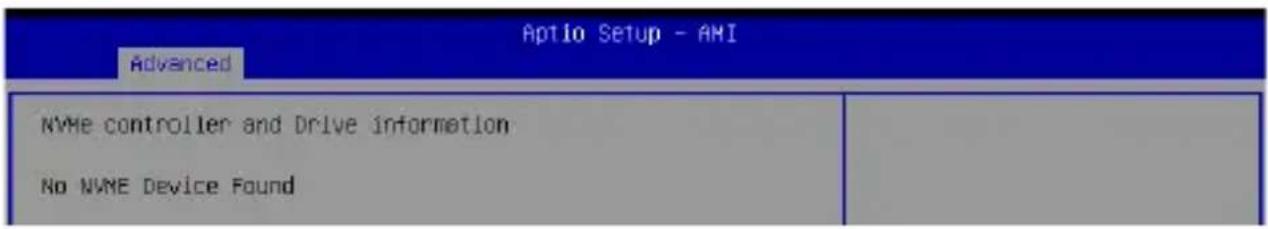
4.4.11 NVMe Configuration
This menu displays the controller and drive information for NVMe devices connected and allows you to configure NVMe device options.
text_image
Aptio Setup - AMI Advanced NVMe controller and Drive information No NVME Device Found4.4.12 Onboard Devices Configuration
| Onboard Devices Configuration | Control Detection of the HD-Audio device. | |
| HD Audio LAN1(I226IT) LAN2(I210IT) | [Enabled] [Enabled] [Enabled] | Disabled = HDA will be unconditionally disabled Enabled = HDA will be unconditionally enabled. |
| M.2_E Key M.2_E(PCIE) M.2_E(USB) | [Enabled] [Enabled] | |
| M.2_B Key M.2_B(PCIE) M.2_B(USB) | [Enabled] [Enabled] | |
| M.2_N Key M.2_N(PCIE) I2C1 Controller | [Enabled] [Enabled] | +: Select Screen ↑↓: Select Item Enter: Select +/-: Change Opt. F1: General Help |
HD Audio
Allows you to enable or disable HD audio support.
Configuration options: [Disabled] [Enabled]
LAN1(I226IT)
Allows you to enable or disable LAN1.
Configuration options: [Enabled] [Disabled]
LAN2(I210IT)
Allows you to enable or disable LAN 2.
Configuration options: [Disabled] [Enabled]
M.2\_E Key
M.2\_E(PCIE) Port
Allows you to enable or disable the M.2 E-Key (PCIe) controller.
Configuration options: [Disabled] [Enabled]
M.2\_E(USB) Port
Allows you to enable or disable the M.2 E-Key (USB) controller.
Configuration options: [Disabled] [Enabled]
M.2\_M(PCIE) Port
Allows you to enable or disable the M.2 M-Key (PCIe) controller. Configuration options: [Disabled] [Enabled]
I2C1 Controller
Allows you to enable or disable I2C controller support. Configuration options: [Disabled] [Enabled]
4.4.13 APM Configuration
Allows you to configure the Advance Power Management (APM) settings.
| Aptio Setup - AMI | |
| APM Configuration | Allow BIOS to switch off some power at S4/S5 to get the system ready for ErF requirement. When set to Enabled, all other PME options will be switched off. |
| ErP Ready [Disabled] | |
| Restore AC Power Loss [S5 State] | |
| Power On By PCIE [Disabled] | |
| Power On By Ring [Disabled] | |
| Power On By RTC [Disabled] | |
ErP Ready
Allows the BIOS to switch off some power at S4/S5 to get the system ready for ErP requirement.
Configuration options: [Disabled] [Enabled]
NOTE: When set to [Enabled], all other PME options will be switched off.
Restore AC Power Loss
[S5] The system goes into OFF state after an AC power loss.
[S0] The system goes into ON state after an AC power loss.
Power On By PCIE
Allows you to enable or disable the wake-on-LAN function for the onboard LAN controller or other installed PCIe/PCI LAN cards.
Configuration options: [Disabled] [Enabled]
Power On By Ring
[Disabled] Disables the Ring devices to generate a wake event.
[Enabled] Enables the Ring devices to generate a wake event.
Power On By RTC
Allows you to disable the real-time clock (RTC) or enable it to schedule a wake event.
Configuration options: [Disabled] [Single event] [Daily event] [Weekly event] [Monthly event]
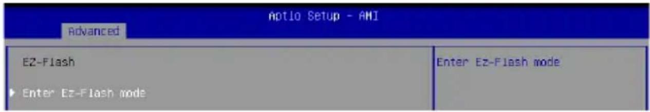
4.4.14 EZ-Flash
text_image
Aptio Setup - AMI Advanced EZ-Flash Enter Ez-Flash mode Enter Ez-Flash modeEnter Ez-Flash mode
Allows you to enter Ez-Flash mode to run the ASUS Ez-Flash BIOS ROM utility.
WARNING! Make sure to back up your Bitlocker recovery key and suspend Bitlocker encryption in the operating system before updating your BIOS.
4.4.15 Watchdog Timer
The items in this menu allow you to configure settings related to Watchdog Timer.

text_image
Aptio Setup - AMI Advanced Hatchdog Timer Hatchdog Support [Enabled] Hatchdog Count Mode [Second Mode] Hatchdog Timer 120 Enable/Disable Hatchdog SupportWatchdog Support
Allows you to enable or disable Watchdog Support.
Configuration options: [Disabled] [Enabled]
NOTE: The following items appear only when Watchdog Support is set to [Enabled].
Watchdog Count Mode
Allows you to select the Watchdog Timer count mode.
Configuration options: [Second Mode] [Minute Mode]
Watchdog Timer
Allows you to input the Watchdog time-out interval.
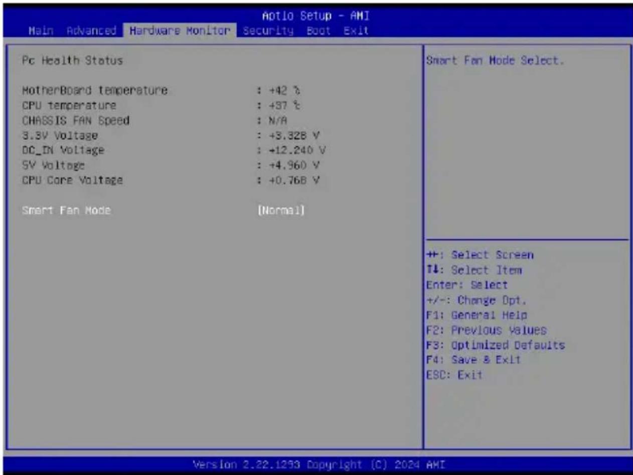
4.5 Hardware Monitor menu
The Hardware Monitor menu displays the system temperature/power status, and allows you to change the fan mode.
text_image
Aotio Setup - AMI Main Advanced Hardware Monitor Security Boot Exit Pc Health Status MotherBoard temperature : +42 °C CPU temperature : +37 °C CHASSIS FAN Speed : N/A 3.3V Voltage : +3.328 V DC_IN Voltage : +12.240 V 5V Voltage : +4.960 V CPU Core Voltage : +0.768 V Smart Fan Mode [Normal] Smart Fan Mode Select. ++: Select Screen T↓: Select Item Enter: Select +/-: Change Opt. F1: General Help F2: Previous Values F3: Optimized Defaults F4: Save & Exit ESC: Exit Version 2.22.1253 Copyright (C) 2024 AMISmart Fan Mode
Allows you to select a smart fan mode.
Configuration options: [Disabled] [Normal] [Manual Mode]
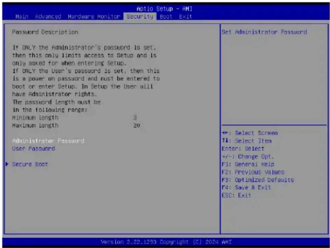
4.6 Security menu
This menu allows a new password to be created or a current password to be changed. The menu also enables or disables the Secure Boot state and lets the user configure the System Mode state.
text_image
Password Description If ONLY the Administrator's password is set, then this only limits access to Setup and is only asked for when entering Setup. If ONLY the User's password is set, then this is a power on password and must be entered to boot or enter Setup. In Setup the User will have Administrator rights. The password length must be in the following range: Minimum Length 3 Maximum Length 20 Administrator Password User Password Secure Boot Set Administrator Password +: Select Screen T↓: Select Item Enter: Select +/-: Change Opt. F1: General Help F2: Previous Values F3: Optimized Defaults F4: Save & Exit ESC: Exit Version 2.22.1293 Copyright (C) 2024 AMIAdministrator Password
To set an administrator password:
- Select the Administrator Password item and press
. - From the Create New Password box, key in a password, then press
. - Confirm the password when prompted.
To change an administrator password:
- Select the Administrator Password item and press
. -
From the Enter Current Password box, key in the current password, then press
. -
From the Create New Password box, key in a new password, then press
. -
Confirm the password when prompted.
NOTE: To clear the administrator password, follow the same steps as in changing an administrator password, but press
User Password
To set a user password:
- Select the User Password item and press
. - From the Create New Password box, key in a password, then press
. - Confirm the password when prompted.
To change a user password:
- Select the User Password item and press
. - From the Enter Current Password box, key in the current password, then press
. - From the Create New Password box, key in a new password, then press
. - Confirm the password when prompted.
To clear a user password:
- Follow the same steps as in changing a user password, but press
when prompted to create a new password. - Select Yes from the Warning message window, then press
.
Secure Boot
Secure Boot can be enabled if the system is running in User mode with enrolled platform Key (EPK) or if the CSM function is disabled.
Configuration options: [Disabled] [Enabled]
Secure Boot Mode
In Custom Mode, the secure boot policy variables can be configured by a physically present user without full authentication.
Configuration options: [Standard] [Custom]
Key Management
The Key Management item allows you to modify Secure Boot variables and set Key Management page.
Platform Key (PK)
Configuration options: [Details] [Export] [Update] [Delete]
Key Exchange Keys / Authorized Signatures / Forbidden Signatures
Configuration options: [Details] [Export] [Update] [Append] [Delete]
HDD Security Configuration
The HDD Security Configuration item allows you to set up passwords to protect your HDD.
NOTE: This item is only available when you have a SATA HDD connected.
To set a password for your HDD:
- Select the HDD Security Configuration item and press
. - Select the Set Master Password item and press
. - From the Create New Password box, key in a password, then press
. - Confirm the password when prompted.
- Select the User Password item and press
. - From the Create New Password box, key in a password, then press
. - Confirm the password when prompted.
To change the password for your HDD:
- Select the HDD Security Configuration item and press
. - Select the Set User Password item and press
. - From the Enter Current Password box, key in a password, then press
. - From the Create New Password box, key in a password, then press
. - Confirm the password when prompted.
NOTE: To clear the user password, follow the same steps as in changing a user password, but press
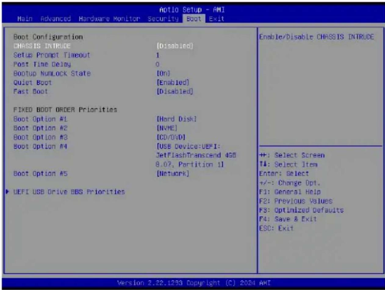
4.7 Boot menu
The Boot menu items allow you to change the system boot options.
text_image
Aptio Setup - AMI Main Advanced Hardware Monitor Security Boot Exit Boot Configuration CHASSIS INTRUDE [Disabled] Setup Prompt Timeout 1 Post Time Delay 0 Bootup NumLock State [On] Quiet Boot [Enabled] Fast Boot [Disabled] FIXED BOOT ORDER Priorities Boot Option #1 [Hard Disk] Boot Option #2 [NVME] Boot Option #3 [CD/DVD] Boot Option #4 [USB Device:UEFI: JetFlashTranscend 4GB 8.07, Partition 1] Boot Option #5 [Network] ▶ UEFI USB Drive BBS Priorities Enable/Disable CHASSIS INTRUDE +: Select Screen T↓: Select Item Enter: Select +/-: Change Opt. F1: General Help F2: Previous Values F3: Optimized Defaults F4: Save & Exit ESC: Exit Version 2.22.1293 Copyright (C) 2024 AMIBoot Configuration
CHASSIS INTRUDE
Allows you to enable or disable the chassis intrusion detection function. Configuration options: [Disabled] [Enabled]
Setup Prompt Timeout
Allows you to set the number of seconds that the firmware waits before initiating the original default boot selection. 65535(OxFFFF) means indefinite waiting. Use <+> or <-> to adjust the value.
Bootup NumLock State
Allows you to select the power-on state for the NumLock. Configuration options: [On] [Off]
Quiet Boot
Allows you to enable or disable the Quiet Boot option. Configuration options: [Disabled] [Enabled]
Fast Boot
[Disabled] Allows your system to go back to its normal boot speed. [Enabled] Allows your system to accelerate the boot speed.
FIXED BOOT ORDER Priorities
These items specify the boot device priority sequence from the available devices. The number of device items that appears on the screen depends on the number of devices installed in the system.
NOTE:
- To access Windows® OS in Safe Mode, press
after POST (Windows® 8 not supported). - To select the boot device during system startup, press
when the ASUS Logo appears.
UEFI Hard Disk Drive BBS Priorities
Allows you to specify the Boot Device Priority sequence from available UEFI Hard Disk Drives.
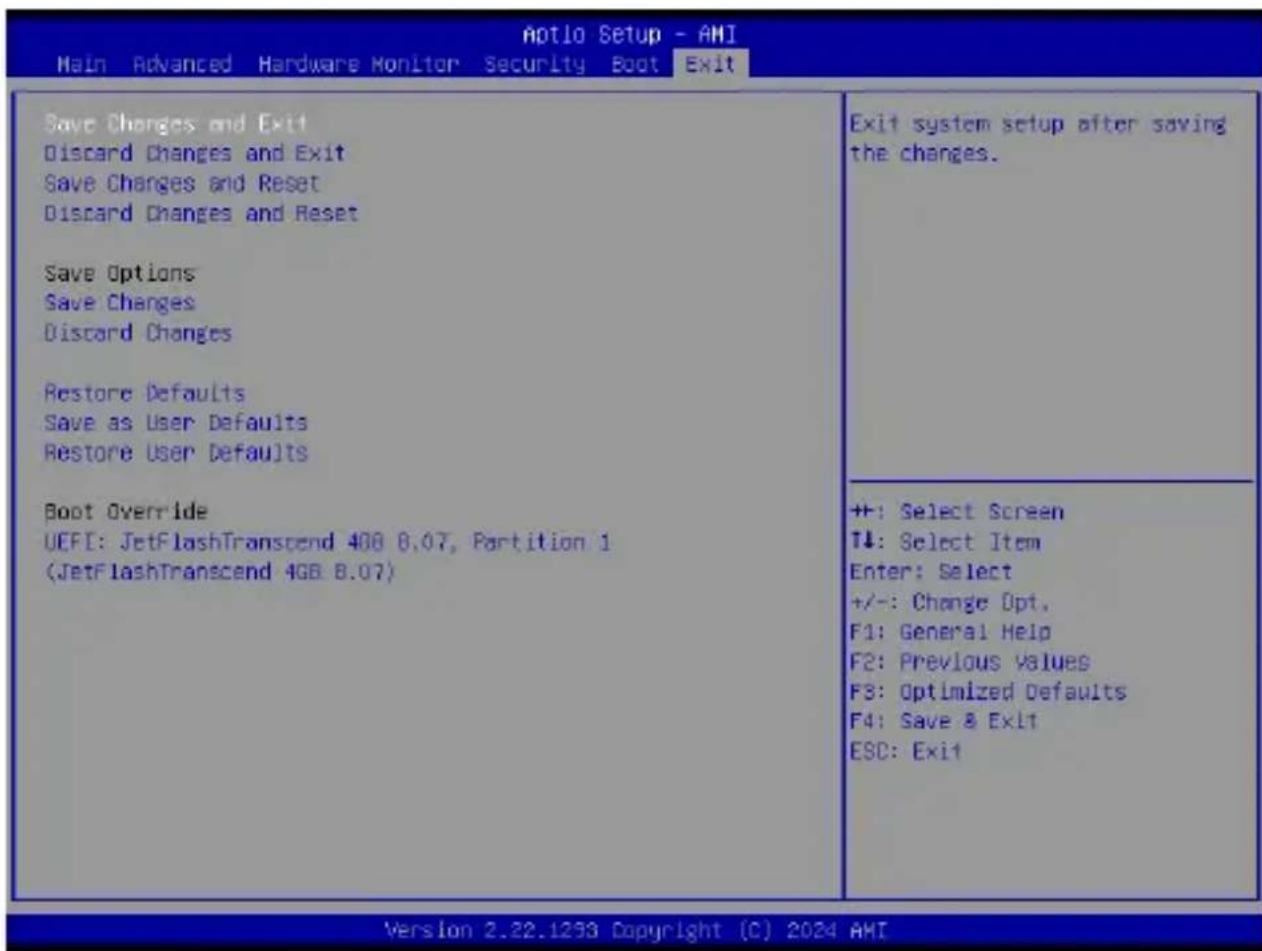
4.8 Exit menu
The Save & Exit menu items allow you to save or discard your changes to the BIOS items.
text_image
Aptio Setup - AMI Main Advanced Hardware Monitor Security Boot Exit Save Changes and Exit Discard Changes and Exit Save Changes and Reset Discard Changes and Reset Save Options Save Changes Discard Changes Restore Defaults Save as User Defaults Restore User Defaults Boot Override UEFI: JetFlashTranscend 408 8.07, Partition 1 (JetFlashTranscend 4GB 8.07) Exit system setup after saving the changes. ++: Select Screen T↓: Select Item Enter: Select +/-: Change Opt. F1: General Help F2: Previous Values F3: Optimized Defaults F4: Save & Exit ESC: Exit Version 2.22.1253 Copyright (C) 2024 AMINOTE: Pressing
Save Changes and Exit
Exit system setup after saving changes.
Discard Changes and Exit
Exit system setup without saving changes.
Save Changes and Reset
Exit system setup after saving changes.
Discard Changes and Reset
Reset the system without saving any changes.
Save Option
Save Changes
Save changes done so far to any of the setup options.
Discard Changes
Discard changes done so far to any of the setup options.
Restore Defaults
Restore/load default values for all the setup options.
Save as User Defaults
Save the changes done so far as User Defaults.
These item displays the available devices. The number of device items that appear on the screen depends on the number of devices installed in the system. Click an item to start booting from the selected device.
4.9 Updating your BIOS
The following utilities allow you to manage and update the Single Board Computer Basic Input/Output System (BIOS) setup:
1. ASUS CrashFree BIOS
To recover the BIOS using a bootable USB flash disk drive when the BIOS file fails or is corrupt.
2. ASUS EZ-Flash
Updates the BIOS using a USB flash disk.
Refer to the corresponding sections for details on these utilities.
4.9.1 ASUS CrashFree BIOS utility
The ASUS CrashFree BIOS is an auto recovery tool that allows you to restore the BIOS file when it fails or gets corrupted during the updating process. You can update a corrupted BIOS file using a USB flash drive that contains the updated BIOS file.
IMPORTANT! Prepare a USB flash drive containing the updated Single Board Computer BIOS before using this utility.
Recovering the BIOS from a USB flash drive
To recover the BIOS from a USB flash drive:
-
Insert the USB flash drive with the original or updated BIOS file to one of the USB ports on the system.
-
The utility will automatically recover the BIOS. It resets the system when the BIOS recovery finished.
WARNING! DO NOT shut down or reset the system while recovering the BIOS! Doing so will cause system boot failure!
NOTE: The recovered BIOS may not be the latest BIOS version for this Single Board Computer. Visit the ASUS website at www.asus.com to download the latest BIOS file.
4.9.2 ASUS EZ-Flash Utility
The ASUS EZ-Flash Utility feature allows you to update the BIOS using a USB flash disk without having to use a DOS-based utility.
IMPORTANT! Download the latest BIOS from the ASUS website at www.asus.com before using this utility.
NOTE: The succeeding BIOS screens are for reference only. The actual BIOS screen displayed may not be the same as shown.
To update the BIOS using EzFlash Utility:
- Insert the USB flash disk that contains the latest BIOS file to a USB port.
- Enter the BIOS setup program. Go to the Advanced menu > EZ-Flash > Enter Ez-Flash mode. Select Yes and then OK to auto reboot and enter EZ-Flash mode.
WARNING! Make sure to back up your Bitlocker recovery key and suspend Bitlocker encryption in the operating system before updating your BIOS.
-
Use the Up/Down arrow keys to find the USB flash disk that contains the latest BIOS, and then press
. -
Use the Up/Down arrow keys to find the BIOS file then press
.
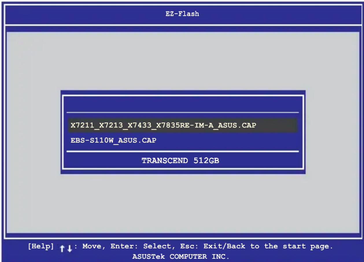
text_image
EZ-Flash X7211_X7213_X7433_X7835RE-IM-A_ASUS.CAP EBS-S110W_ASUS.CAP TRANSCEND 512GB [Help] ↑↓ : Move, Enter: Select, Esc: Exit/Back to the start page. ASUSTek COMPUTER INC.- Reboot the system when the update process is done.
WARNING!
- This function can support devices such as a USB flash disk with FAT 32/16 format and single partition only.
- DO NOT shut down or reset the system while updating the BIOS to prevent system boot failure!
IMPORTANT! Make sure to load the BIOS default settings to ensure system compatibility and stability. Press
Appendix
Safety information
Your Single Board Computer is designed and tested to meet the latest standards of safety for information technology equipment. However, to ensure your safety, it is important that you read the following safety instructions.
Setting up your system
- Read and follow all instructions in the documentation before you operate your system.
- Do not use this product near water or a heated source.
- Set up the system on a stable surface.
- Peripherals with extended temperature tolerance (such as industrial grade DRAM, SSD) will allow this product to be used in environments with ambient temperatures between -20^ and 70^ , with a 0.1m/s airflow.
- The product should be used in environments with an ambient temperature of 40^ when using the 90 W adapter.
- If you use an extension cord, make sure that the total ampere rating of the devices plugged into the extension cord does not exceed its ampere rating.
- This equipment should be installed and operated with a minimum distance of 20 cm between the radiator and your body.
- Restricted Access Area:
The equipment should only be installed in a Restricted Access Area where both these conditions apply:
- access can only be gained by skilled persons who have been instructed about the reasons for the restrictions applied to the area and about any precautions that shall be taken; and
- access is through the use of a TOOL or lock and key, or other means of security, and is controlled by the authority responsible for the area.
- This device shall not be connected to an Ethernet network with outside plant routing.
Care during use
- Do not walk on the power cord or allow anything to rest on it.
- Do not spill water or any other liquids on your system.
- When the system is turned off, a small amount of electrical current still flows. Always unplug the power cord from the power outlets before cleaning the system.
- If you encounter the following technical problems with the product, unplug the power cord and contact a qualified service technician or your retailer.
- The power cord or plug is damaged.
– Liquid has been spilled into the system.
- The system does not function properly even if you follow the operating instructions.
- The system was dropped or the cabinet is damaged.
- The system performance changes.
Safety Precautions
Accessories that came with this product have been designed and verified for the use in connection with this product. Never use accessories for other products to prevent the risk of electric shock or fire."
Lithium-Metal Battery Warning
CAUTION: Danger of explosion if battery is incorrectly replaced. Replace only with the same or equivalent type recommended by the manufacturer. Dispose of used batteries according to the manufacturer's instructions.
NO DISASSEMBLY
The warranty does not apply to the products that have been disassembled by users

DO NOT throw the Single Board Computer in municipal waste. This product has been designed to enable proper reuse of parts and recycling. This symbol of the crossed out wheeled bin indicates that the product (electrical, electronic equipment, and mercury-containing button cell battery) should not be placed in municipal waste. Check local technical support services for product recycling.
Regulatory notices
COATING NOTICE
IMPORTANT! To provide electrical insulation and maintain electrical safety, a coating is applied to insulate the device except on the areas where the I/O ports are located.
FCC RF Exposure Information
This device meets the government's requirements for exposure to radio waves. This device is designed and manufactured not to exceed the emission limits for exposure to radio frequency (RF) energy set by the Federal Communications Commission of the U.S. Government. The exposure standard employs a unit of measurement known as the Specific Absorption Rate, or SAR. The SAR limit set by the FCC is 1.6 W/kg. Tests for SAR are conducted using standard operating positions accepted by the FCC with the EUT transmitting at the specified power level in different channels. The FCC has granted an Equipment Authorization for this device with all reported SAR levels evaluated as in compliance with the FCC RF exposure guidelines. SAR information on this device is on file with the FCC and can be found under the Display Grant section of www.fcc.gov/oet/ea/fccid.
Federal Communications Commission Statement
This device complies with Part 15 of the FCC Rules. Operation is subject to the following two conditions:
- This device may not cause harmful interference, and
- This device must accept any interference received including interference that may cause undesired operation.
This equipment has been tested and found to comply with the limits for a Class A digital device, pursuant to part 15 of the FCC Rules. These limits are designed to provide reasonable protection against harmful interference when the equipment is operated in a commercial environment.
This equipment generates, uses, and can radiate radio frequency energy and, if not installed and used in accordance with the instruction manual, may cause harmful interference to radio communications. Operation of this equipment in a residential area is likely to cause harmful interference in which case the user will be required to correct the interference at his own expense.
IMPORTANT! Outdoor operations in the 5.15\~5.25 GHz band is prohibited. This device has no Ad-hoc capability for 5250\~5350 and 5470\~5725 MHz.
CAUTION! Any changes or modifications not expressly approved by the party responsible for compliance could void the user's authority to operate the equipment.
ISED Radiation Exposure Statement for Canada
This equipment complies with ISED radiation exposure limits set forth for an uncontrolled environment. To maintain compliance with ISED RF exposure compliance requirements, please avoid direct contact to the transmitting antenna during transmitting. End users must follow the specific operating instructions for satisfying RF exposure compliance.
Operation is subject to the following two conditions:
• This device may not cause interference and
- This device must accept any interference, including interference that may cause undesired operation of the device.
Compliance Statement of Innovation, Science and Economic Development Canada (ISED)
This device complies with Innovation, Science and Economic Development Canada licence exempt RSS standard(s). Operation is subject to the following two conditions: (1) this device may not cause interference, and (2) this device must accept any interference, including interference that may cause undesired operation of the device.
CAN ICES-003(A)/NMB-003(A)
Wireless Operation Channel for Different Domains
N. America 2.412-2.462 GHz Ch01 through CH11
Japan 2.412-2.484 GHz Ch01 through Ch14
Europe ETSI 2.412-2.472 GHz Ch01 through Ch13
Regional notice for Singapore
Complies with IMDA Standards DB103778
This ASUS product complies with IMDA Standards.
Regional notice for Malaysia

text_image
MCMC CIDF15000026HDMI Trademark Notice
The terms HDMI, HDMI High-Definition Multimedia Interface, HDMI Trade Dress, and the HDMI Logos are trademarks or registered trademarks of HDMI Licensing Administrator, Inc.
Declaration of compliance for product environmental regulation
ASUS follows the green design concept to design and manufacture our products, and makes sure that each stage of the product life cycle of ASUS product is in line with global environmental regulations. In addition, ASUS disclose the relevant information based on regulation requirements.
Please refer to https://esg.asus.com/Compliance.htm for information disclosure based on regulation requirements ASUS is complied with.
EU REACH and Article 33
Complying with the REACH (Registration, Evaluation, Authorization, and Restriction of Chemicals) regulatory framework, we publish the chemical substances in our products at ASUS REACH website at https://esg.asus.com/Compliance.htm
EU RoHS
This product complies with the EU RoHS Directive. For more details, see https://esg.asus.com/Compliance.htm
Japan JIS-C-0950 Material Declarations
Information on Japan RoHS (JIS-C-0950) chemical disclosures is available on https://esg.asus.com/Compliance.htm
India RoHS
This product complies with the “India E-Waste (Management) Rules, 2016” and prohibits use of lead, mercury, hexavalent chromium, polybrominated biphenyls (PBBs) and polybrominated diphenyl ethers (PBDEs) in concentrations exceeding 0.1% by weight in homogenous materials and 0.01% by weight in homogenous materials for cadmium, except for the exemptions listed in Schedule II of the Rule.
Vietnam RoHS
ASUS products sold in Vietnam, on or after September 23, 2011, meet the requirements of the Vietnam Circular 30/2011/TT-BCT.
ASUS recycling and takeback programs come from our commitment to the highest standards for protecting our environment. We believe in providing solutions for you to be able to responsibly recycle our products, batteries, other components as well as the packaging materials. Please go to https://esg.asus.com/en/Takeback.htm for detailed recycling information in different regions.
Ecodesign Directive
The European Union announced a framework for the setting of ecodesign requirements for energy-related products (2009/125/EC). Specific implementing measures are aimed at improving environmental performance of specific products or across multiple product types. ASUS provides product information at https://esg.asus.com/Compliance.htm.

DO NOT throw the device in municipal waste. This product has been designed to enable proper reuse of parts and recycling. This symbol of the crossed out wheeled bin indicates that the product (electrical, electronic equipment, and mercury-containing button cell battery) should not be placed in municipal waste. Check local technical support services for product recycling.
EPEAT (Electronic Product Environmental Assessment Tool) registered products
The public disclosure of key environmental information for ASUS EPEAT registered products is available at https://esg.asus.com/en/Ecolabel.htm. More information about EPEAT program and purchaser guidance can be found on the EPEAT website www.epeat.net.
ENERGY STAR® Qualified Product
ENERGY STAR® is a joint program of the U.S. Environmental Protection

text_image
ENERGY ENERGY STARAgency and the U.S. Department of Energy helping us all save money and protect the environment through energy efficient products and practices.
All ASUS products with the ENERGY STAR® logo comply with the ENERGY STAR® standard, and the power management feature is enabled by default. The monitor is automatically set to sleep within 10 minutes of user inactivity; the computer is
automatically set to sleep within 30 minutes of user inactivity. To wake your computer, click the mouse, press any key on the keyboard, or press the power button.
Please visit https://www.energystar.gov for detailed information on the ENERGY STAR® joint program, power management, and the benefits to the environment.
NOTE: ENERGY STAR® is NOT supported on FreeDOS and Linux-based products.
Service and Support
Visit our multi-language website at https://www.asus.com/support.
