RANGER 48 PUSH - Lawn mower Hayter - Free user manual and instructions
Find the device manual for free RANGER 48 PUSH Hayter in PDF.

User questions about RANGER 48 PUSH Hayter
0 question about this device. Answer the ones you know or ask your own.
Ask a new question about this device
Download the instructions for your Lawn mower in PDF format for free! Find your manual RANGER 48 PUSH - Hayter and take your electronic device back in hand. On this page are published all the documents necessary for the use of your device. RANGER 48 PUSH by Hayter.
USER MANUAL RANGER 48 PUSH Hayter
I, the undersigned M.A. Wright, of:
HAYTER LIMITED, Spellbrook, Bishop's Stortford Herts CM23 4BU ENGLAND
certify that the lawnmowers:
- Machine Type No. 397S 398S 399S
- Category. Combustion Engine Combustion Engine Combustion Engine
- Make. Hayter Hayter Hayter
- Type. Rotary Rotary Rotary
- Engine - Manufacturer.
- Type.
- Speed of rotation during test.
Briggs & Stratton
127802-1592-21
2830rpm
Briggs & Stratton
127802-1592-21
2830rpm
Briggs & Stratton
127802-1592-21
3000rpm
Conforms to the specifications of Directive 84/538/EEC as adapted to technical progress by Directive 87/252/EEC and amended by Directive 88/180/EEC.
Guaranteed maximum sound power level. 96dB(A) 96dB(A) 100dB(A)
| - Type of cutting device | Cutterbar | Cutterbar | Cutterbar |
| - Width of cutting device | 48cm | 48cm 53cm | |
| - Speed of rotation of the cutting device | 2830 rpm | 2830 rpm | 3000 rpm |
TESTED AT SUDBURY, 26/01/99 26/01/99 26/01/99 SUFFOLK, ENGLAND
Signed

M.A. Wright (Technical Director)
EC DECLARATION OF CONFORMITY
Company Name
HAYTER LIMITED
Company Address
Spellbrook Bishop's Stortford Herts. CM23 4BU ENGLAND

Machine Type No.. Models
Code 397S
Code 398S
Code 399S
Directives complied with: 98/37/EC.
Essential Health & Safety Requirements Relating to the Design & Construction of Machinery
and Safety Components.
84/538/EEC amended by 87/252/EEC and 88/180EEC Permissible Sound Power Levels of Lawn Mowers
89/336/EEC amended by 92/31/EEC Electromagnetic Compatibility
Standards Used: EN292, EN836, and ENISO 14982.
I declare on behalf of Hayter Limited that these machines conform to the EC Essential Health & Safety Requirements.
Signed

Date: 6.07.99
M.A. Wright (Technical Director)
VIBRATION INFORMATION
Lawnmower vibration information. RMS acceleration measured in 3 - axes at operators contact position on the handlebars. CODE 397S, 398S = 6.8ms ^-2 CODE 399s = 7.3 ^-2
CONTENTS
1.11.1
| CONTENTS | Page No. |
| INTRODUCTION. | 1.3 |
| WARRANTY. | 1.4 |
| SAFETY PRECAUTIONS. | 1.5 - 1.8 |
| Decals | 1.8 |
| SPECIFICATIONS. | 1.9 |
| ASSEMBLY INSTRUCTIONS. | 1.10 - 1.12 |
| General Assembly. | 1.10 |
| Assembling the Mower for the First Time. | 1.11 - 1.12 |
| STARTING THE ENGINE. | 1.13 - 1.14 |
| Before Starting the Engine. | 1.13 - 1.14 |
| To Start the Engine. | 1.14 |
| STOPPING THE ENGINE. | 1.15 |
| OPERATING THE MOWER. | 1.16 - 1.21 |
| Height of Cut. | 1.16 |
| Travel. | 1.17 |
| Turning the Mower. | 1.17 |
| Mowing with Grass Collection. | 1.18 |
| Mowing without Grass Collection. | 1.19 |
| Heavy Growth. | 1.19 |
| Moving the Mower Across Non-Grassed Areas. | 1.19 |
| Cutterbar Operation. | 1.20 |
| Mowing and Grass Care Tips. | 1.20 - 1.21 |
| MAINTENANCE. | 1.22 - 1.29 |
| Engine. | 1.22 |
| Oil Service | 1.23 |
| Air Cleaner Service | 1.24 |
| Grassbag | 1.24 |
| Deck Housing | 1.24 |
| Securing Nuts and Bolts | 1.25 |
| Lubrication | 1.25 |
| Speed Change Cable | 1.25 |
| Clutch Cable Adjustment | 1.26 |
| Cutterbar | 1.26 - 1.27 |
| Maintenance Schedule | 1.28 - 1.29 |
| - After First 5 Hours | 1.28 |
| - Every 5 Hours or Daily | 1.28 |
| - Every 25 Hours or Every Season | 1.28 |
| - Every 50 Hours or Every Season | 1.29 |
| - Every 100 Hours or Every Season | 1.29 |
CONTENTS
1.21.2
| CONTENTS | Page No. |
| PREPARING THE MOWER FOR STORAGE. | 1.30 |
| FAULT FINDING. | 1.31 - 1.33 |
| 397S, 398S, 399S PARTS LIST. | 2.1 - 2.3 |
| 397S PARTS LIST DIAGRAM. | 2.4 |
| 398S PARTS LIST DIAGRAM. | 2.5 |
| 399S PARTS LIST DIAGRAM. | 2.6 |
| ENGINE ANCILLARY PARTS | 2.7 |
| ENGINE WARRANTY | 2.8 |
| NOTES | 2.9 |
| CUSTOMER INFORMATION | 2.10 |
INTRODUCTION
Thank you for purchasing a Hayter mower. The following pages are designed to help you gain safe and efficient service from your machine.
IMPORTANT: This ‘Owners Handbook’ should be regarded as part of the machine as it gives essential information regarding machine safety, operation, maintenance and specifications. Read and understand this handbook prior to operating your machine for the first time. Make sure you are familiar with all the controls and points of regular maintenance. If you have any doubts, consult your Hayter authorised dealer who will be pleased to give you assistance.
IMPORTANT: This machine is designed solely for use in a domestic grass cutting environment. Use in any other way is considered as contrary to the intended use. Compliance with and strict adherence to the conditions of operation, service and repair as specified in this handbook also constitute essential elements of the intended use.
This machine should be operated, serviced and repaired only by persons who are familiar with its particular characteristics and who are acquainted with the relevant safety procedures.
The safety precautions listed here in and all other generally recognised regulations on safety must be observed at all times.
Any arbitrary modifications carried out to this machine may relieve Hayter Limited of liability for any resulting damage or injury.
All Hayter mowers are robustly constructed and designed for efficient economical performance under normal mowing conditions. Correct operation and maintenance will ensure a long and satisfactory service life. Prior to despatch from our factory every effort is made to ensure your machine arrives in perfect condition. Your dealer will carry out a pre-delivery inspection to ensure that there has been no transit damage prior to installation.
Please allow your dealer to familiarise you with the controls and safety features of the machine during installation.
Throughout this handbook all references to left hand and right hand are as viewed from behind the handlebar, facing in the direction of forward travel.
This owners handbook is based on information available at the time of publication.
HAYTER LIMITED reserve the right to make changes at any time without notice.
LIMITED WARRANTY
Hayter Limited warrants to the original user/purchaser that this unit shall be free from defects in material and workmanship under normal use and service for a period of three years from the date of purchase. The manufacturers of the engine and battery pack system (where applicable) furnish their own warranty and services are provided through their authorised network (Refer to "Engine/Battery Pack Warranty Statement"). To qualify for the full benefit of the warranty, the warranty registration card must be returned within 60 days of purchase. Subject to the conditions and exclusions noted in this limited warranty, we shall at our option, repair or replace any warranted part during the applicable period. If you are in doubt or experience any difficulty, please consult a Hayter Authorised Service Dealer for clarification.
To qualify for the extended warranty (second and third year) of the three year limited warranty the machine must have annual services carried out by an Authorised Hayter Service Dealer. These chargeable services should be carried out within 12 and 24 months of the date of purchase.
Excluded from the extended warranty period are those items which are subject to normal wear and tear e.g. tyres, wheels, cutterbars, cables, batteries and other consumable wearing parts.
All consumer machines which are fitted with a genuine Hayter friction disc as original equipment before use, are covered by a Lifetime Warranty against the engine crankshaft bending. Note: friction washers, blade brake units and other such devices are not applicable. Only machines fitted with a genuine Hayter friction disc, which are used in accordance with the recommended operating and maintenance procedures, are covered.
This warranty does not apply to any unit that has been tampered with, altered, misused, abused or used for hire, and will become invalid if non genuine Hayter parts are fitted. This warranty does not cover minor mechanical adjustments unless they are due to defective material or workmanship. Consult the Owner's Handbook or a Hayter Authorised Service Dealer for assistance when making these adjustments.
A warranty period of 90 days applies to machines used for commercial purposes.
To make a warranty claim, return the unit to a Hayter authorised dealer along with proof of purchase stating the machine serial number and date of purchase. The service receipt(s) or this Owners Handbook with the 1st/2nd year service boxes fully completed, must be produced as proof of entitlement to the extended warranty period. Subject to the conditions and exclusions in this limited warranty, the authorised dealer will, at our option, repair or replace any warranted part within the duration of the warranty period.
This limited warranty gives you specific legal rights and is in addition to any statutory rights to which you may be entitled and your statutory rights are not affected by this warranty. If you need additional information concerning this written warranty, or assistance in obtaining services, please write to : HAYTER LIMITED, Service Department, Spellbrook, Bishop's Stortford, Hertfordshire CM23 4BU
UK ONLY: Details of your local Hayter authorised dealer are contained in Yellow Pages or contact:- Freephone 0800 616298.

text_image
1st Year Service Record DEALER STAMP 2nd Year Service Record DEALER STAMP Date..... Signed..... Date..... Signed.....SAFETY PRECAUTIONS

THIS SYMBOL MEANS BE ALERT! YOUR SAFETY IS INVOLVED. WHEN YOU SEE THIS SYMBOL BE ALERT TO THE POSSIBILITY OF INJURY. CAREFULLY READ THE MESSAGE THAT FOLLOWS AND INFORM OTHERS. EXERCISE GREAT CARE AND FOLLOW THE ADVICE GIVEN TO AVOID POTENTIALLY HAZARDOUS SITUATIONS.
The Ranger is perfectly safe if used correctly. Failure to observe the following simple precautions may result in serious injury.
Training:

Read the instructions carefully. Ensure that you are familiar with the controls and the proper use of the equipment. Learn how to stop the mower quickly in an emergency.

Never allow children or people unfamiliar with these instructions to use the mower.

Never mow while people, especially children, or pets are nearby.

Keep in mind that the user is responsible for accidents or hazards occurring to other people or their property.
Preparation:

While mowing, always wear substantial footwear and long trousers. Do not operate the equipment when barefoot or wearing sandals.

Thoroughly inspect the area where the mower is to be used and remove all objects which may be thrown by the machine.

WARNING: Petrol is highly flammable.
- Store fuel in containers specifically designed for this purpose.
- Refuel outdoors only and do not smoke while refuelling.
- Add fuel before starting the engine. Never remove the cap from the fuel tank or add petrol while the engine is running or when the engine is hot. Allow the engine to cool for at least 2 minutes before refuelling.
- If petrol is spilled, do not attempt to start the engine but move the mower away from the area of spillage. Avoid creating any source of ignition until petrol vapours have dissipated.
- Always use fresh fuel. Stale fuel can block the carburettor.
- Replace fuel tank caps and fuel container caps securely.

Replace faulty exhaust mufflers.
SAFETY PRECAUTIONS
1.61.6
SAFETY PRECAUTIONS
Continued.

Always ensure that the mower is in a safe operating condition. Frequently check all nuts, bolts and screws for tightness. Use only genuine Hayter replacement parts.

A damaged cutterbar or loose fixing bolt are major hazards. Before use, visually inspect the cutting mechanism to ensure that it is in good condition. A damaged cutterbar must be replaced immediately with a genuine Hayter replacement part. Cutterbars which are slightly worn can be resharpened. Ensure that both cutting edges are resharpened equally to maintain balance. An unbalanced cutterbar may cause serious damage to your machine. Refer to "Maintenance."
Operation:

Do not operate the engine in a confined space where dangerous carbon monoxide fumes can collect.

Always pull starter cord slowly until resistance is felt. Then pull the cord rapidly to avoid kickback and prevent hand or arm injury.

Mow only in daylight or good artificial light.

Avoid using the mower on wet grass, where feasible.

Always be sure of your footing on slopes.

Walk, never run.

Mow across the face of slopes, never up and down.

Exercise extreme caution when changing direction on slopes.

Do not mow excessively steep slopes.

Use extreme caution when reversing or pulling the mower towards you.

Stop the engine if the mower has to be tilted for transportation when crossing surfaces other than grass and when transporting the mower to and from the area to be mowed.

Never operate the mower unless the guards are securely in position and in good condition.

Do not change the engine governor settings or overspeed the engine.

Disengage the drive clutch before starting the engine. (Auto drive models only).
SAFETY PRECAUTIONS
Continued.
Operation continued:

Start the engine carefully, with feet well away from the cutterbar.

Do not tilt the mower when starting the engine.

Do not put hands or feet near or under rotating parts.

Never pick up or carry a mower while the engine is running.

Stop the engine and disconnect the spark plug lead:
- Before clearing blockages or unclogging the discharge chute.
- Before cleaning/checking or working on the mower.
- After striking a foreign object. Inspect the mower for damage and make repairs before restarting and operating the mower.
- If the mower starts to vibrate abnormally (check immediately).

Stop the engine:
- Whenever you leave the mower.
- Before refuelling.

Never lift the deflector plate whilst the mower is in operation.
Maintenance and Storage:

Keep all nuts, bolts and screws tight to ensure that the equipment is in safe operating condition.

Frequently check fuel lines and fittings for cracks or leaks and replace if necessary.

Never check for a spark with the spark plug removed. (Use an approved tester).

WARNING: THE CUTTERBAR CAN CONTINUE TO ROTATE AFTER THE ENGINE IS SWITCHED OFF.
SAFETY PRECAUTIONS
1.81.8
SAFETY PRECAUTIONS
Continued.

Never crank the engine with the spark plug removed. If the engine is flooded, move the throttle to the 'fast' position and crank the engine until it starts.

Never strike the flywheel with a hammer or hard object as this may cause the flywheel to shatter in operation. Always use the correct tools to service the engine.

Never operate the engine without a muffler guard. Inspect the muffler periodically and replace if worn or leaking.

Never start the engine with the air-cleaner or air-cleaner cover removed.

Never store the mower with petrol in the tank within an enclosed area where fumes may reach an open flame or spark.

Allow the engine to cool before storing in any enclosure.

To reduce the fire hazard, keep the engine, muffler, cooling fins and petrol storage area free of grass, leaves, or excessive grease.

Replace worn or damaged parts for safety.

If the fuel tank has to be drained, it is essential that this be done outdoors.
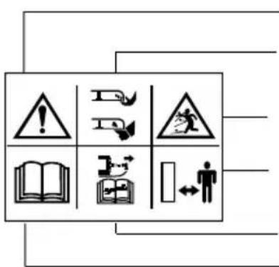
DECALS
WARNING DECAL: Part No. 219189
text_image
Warning sign with warning symbols and icons for education, reading, and safetyWARNING - CAUTION RISK OF DANGER - SAFETY ALERT.
DANGER OF SEVERING TOES OR FINGERS IN CUTTING MECHANISM.
DANGER OF BEING HIT BY THROWN OBJECTS.
KEEP BYSTANDERS AT A SAFE DISTANCE FROM THE MACHINE.
STOP ENGINE AND REMOVE SPARK PLUG LEAD BEFORE PERFORMING MAINTENANCE OR REPAIR WORK.
CAREFULLY READ THE OPERATORS MANUAL BEFORE USING THE MACHINE.
DECAL : HEIGHT OF CUTADJUSTMENT Part No. 320006

DECAL: ENGINE STOP Part No. 331046

THROTTLE CONTROL

SPECIFICATIONS
1.91.9
SPECIFICATIONS
| MODELS | CODE 397S(Push) | CODE 398S(Auto-Drive) | CODE 399S(Auto Drive 4 - Speed) |
| Engine | Briggs & Stratton Quantum XTL 45 | ||
| Engine type | 127802-1592-21 | ||
| Engine / cutterbar speed | 2830rpm 3000rpm | ||
| Fuel type | Unleaded petrol. | ||
| Fuel capacity | 1.5 litres | ||
| Oil type | SAE 30 engine oil | ||
| Oil sump capacity | 0.6 litres | ||
| Cutting width | 480mm 530mm | ||
| Cutting height | 20 - 70mm 30 - 80mm | ||
| Overall dimensions | 1070 x 530 x 1400mm 1080 x 570 x 1560mm | ||
| Dry Weight | 33kg | 33.5kg | 37.5kg |
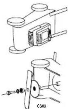
ASSEMBLY INSTRUCTIONS
SAFETY NOTICE

Before using the mower, read this owners handbook carefully. Pay particular attention to the safety precautions.
GENERALASSEMBLY
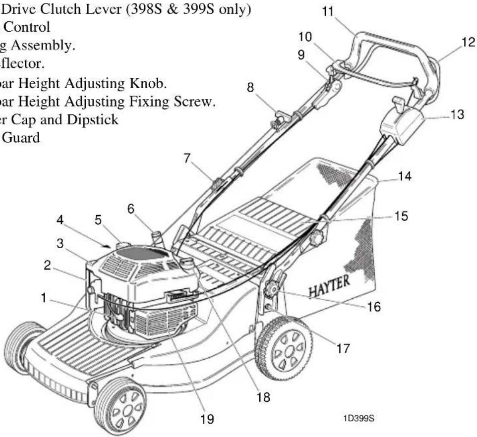
1 Spark Plug lead
2 Air Cleaner
3 Engine Cowl
4 Serial No.Label
5 Fuel Cap.
6 Height of Cut Adjuster.
7 Handlebar Securing Knob.
8 Engine Start-Grip.
9 Variable Speed Control (399S only)
10 Engine Stop lever.
11 Handlebar.
12 Ground Drive Clutch Lever (398S & 399S only)
13 Throttle Control
14 Grassbag Assembly.
15 Rear Deflector.
16 Handlebar Height Adjusting Knob.
17 Handlebar Height Adjusting Fixing Screw.
18 Oil Filler Cap and Dipstick
19 Muffler Guard
text_image
Drive Clutch Lever (398S & 399S only) Control g Assembly. flector. ear Height Adjusting Knob. ear Height Adjusting Fixing Screw. ar Cap and Dipstick Guard HAYTER 1D399SASSEMBLY INSTRUCTIONS
1.111.1
ASSEMBLING THE MOWER FOR THE FIRST TIME
DELIVERY CHECKLIST
Check that parts are delivered correctly: Remove the mower from the packaging and check that all loose items have been supplied correctly. Refer to the delivery checklist opposite and the general assembly. If any items are missing, contact your local authorised Hayter Dealer.
| Description | Quantity |
| Grassbag | 1 |
| Owner's Handbook | 1 |
| Engine Handbook | 1 |
| Warranty Reg. Card | 1 |
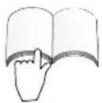
Assemble the handlebar: Unscrew the knobs securing the handlebar sufficiently to allow it to be pivoted. Move the engine stop lever away from the engine to avoid damage and unfold the handlebar to its operating position. Tighten the two knobs to secure the handlebar, ensure that the knobs are assembled to the outside of the handlebars.

natural_image
Diagram of a car with an open trunk and curved arrow indicating motion (no text or symbols)CAUTION - PREVENT DAMAGE : When unfolding the handlebar, take care to ensure that the controls and cables do not become damaged. Always replace damaged controls and cables before using the mower.
Adjust height of handlebars: Using a suitable spanner or socket. Loosen the 2 fixings at the base of the handlebars. Unscrew the 2 lower knobs sufficiently to allow handlebars to pivot. Set the required position and re-tighten the 2 lower knobs, check position and re-tighten the fixing screws at the base of the handlebar.

text_image
HA C0275Assemble the grassbag: Identify the grassbag and remove the long ribbon label by cutting it off close to the grassbag. Discard the ribbon label.

WARNING - AVOID ENTANGLEMENT : Completely remove this ribbon before using the mower.
Raise the rear deflector and lower the grassbag through the handlebar aperture to connect onto the upper mounting points. Lower the grassbag to rest against the rear of the mower. Finally lower the rear deflector to rest against the top of the grassbag.
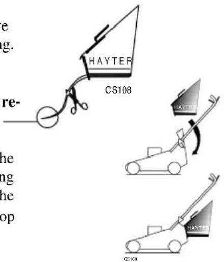
text_image
e g. re- he ng he op HAYTER CS108 HAYTER HAYTER CS108ASSEMBLY INSTRUCTIONS
1.121.12
ASSEMBLING THE MOWER FOR THE FIRST TIME
Continued.
Check that all fasteners are secure.
Check engine stop lever operation: Operate the engine stop lever several times. Ensure that the cable moves freely and that the lever returns automatically to the engine stop position when released.

natural_image
Diagram of a mechanical device with curved blades and a handle, labeled CS011 (no text or symbols on the diagram itself)Check throttle lever operation: Operate the throttle lever several times and ensure that the cable moves freely whilst operating the engine throttle mechanism. Slight resistance should be felt when the lever moves to the 'choke' position.
natural_image
Pure electrical circuit lines without any symbolsAuto Drive Models Only
Check clutch lever operation: Operate the clutch lever several times and ensure that the cable moves freely.
natural_image
Diagram of a mechanical device with curved arrows indicating motion or rotation (no text or symbols)BEFORE STARTING THE ENGINE
IMPORTANT - PREVENT ENGINE DAMAGE: The engine is shipped without oil or petrol. The engine must be filled with the correct grade of oil and petrol before starting the engine.
natural_image
Diagram of a car engine with a lever and valve, showing engine components without any text or symbolsOil recommendations: Always use high quality detergent oil classified "For service SE, SF, SG" SAE 30 oil. Never use additives with recommended oils.
SAE 10W-30 multigrade oil may be used, but this will result in higher engine operating temperatures with consequential high oil consumption. It is imperative that the oil level is checked more frequently if this grade of oil is used in order to guard against serious engine damage.
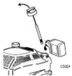
Check oil level: Clean around the oil filler cap before removing. With the mower on a level surface, unscrew and remove the oil filler - dipstick. Wipe oil from it with a clean cloth. Screw the oil filler - dipstick back in place, then unscrew and remove it to check the oil level.
The oil level is correct when it is at the full mark on the dipstick. DO NOT OVERFILL.
Slowly fill with engine oil as necessary and replace the oil filler - dipstick.
IMPORTANT: The oil filler dipstick must be secured to prevent oil leakage during operation.

text_image
0.15 Litres FULL ADD CS028Fuel Recommendations: Always use clean, fresh unleaded petrol. Purchase fuel in quantities which can be used within 30 days. Never mix oil with petrol. For added engine protection Briggs & Stratton recommend the use of their fuel additive which is available from an authorised Briggs & Stratton service dealer.
Check fuel level: Clean around the fuel filler cap before removing and fill the fuel tank with clean unleaded petrol.
Do not overfill the fuel tank. Allow 6mm minimum of tank space for fuel expansion.
IMPORTANT: The fuel filler cap must be secured to prevent fuel leakage during operation.

text_image
6mm minimum CS036BEFORE STARTING THE ENGINE
Continued.

WARNING - PREVENT ACCIDENTS: The cutterbar rotates when the engine is operating.
ALWAYS operate the engine stop lever several times and ensure the engine stop cable moves freely before starting the engine.
ALWAYS position the mower on a level stone free grass surface before starting the engine. Ensure that the cutterbar is set above grass height to prevent the engine being started under load.
natural_image
Two black cross symbols crossed over a wavy surface, no text or labels presentTO START THE ENGINE
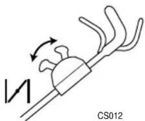
Operate the throttle control lever: Push the lever to 'choke' position before starting a cold engine. It should only be necessary to push the lever to the 'fast' position before starting a warm engine.

natural_image
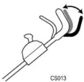
Pure electrical circuit lines without any symbolsOperate the engine stop lever: Use one hand to hold the engine stop lever in the operating position firmly against the handlebar. To start and operate the engine the engine stop lever must be held in the operating position. If the engine stop lever is released the engine will stop.

natural_image
Diagram of a hand holding a curved object with motion arrows, labeled CS032 (no text or symbols on the diagram itself)Operate the engine start - grip: Stand behind the mower and maintain a firm hold on the handlebar and the engine stop lever to prevent the mower moving towards you. Use your right hand to hold the engine start - grip and pull slowly until resistance is felt, then pull rapidly to crank the engine. When the engine starts carefully return the engine start - grip to the storage position. If the engine does not start after 5 attempts - refer to "Fault Finding".

natural_image
Illustration of a hand holding a curved tool with an arrow indicating motion, labeled CS033 (no text or symbols on the diagram itself)Allow the engine to warm up and return the throttle lever to the 'fast' position after starting a cold engine.
IMPORTANT - PREVENT ENGINE DAMAGE: Never pull the engine start - grip when the engine is running.
STOPPING THE ENGINE
1.151.1\$
STOPPING THE ENGINE
Stopping the engine: Reduce the throttle setting and disengage the engine stop lever by releasing the lever.
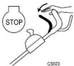
text_image
STOP CS023Emergency stop: If the engine stop lever fails, move the throttle lever to the 'slow' position and disconnect the spark plug lead to stop the engine.
- Engine
- Spark Plug Lead
- Spark plug
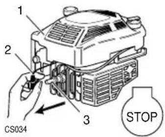
text_image
1 2 CS034 3 STOPSAFETY NOTICE

WARNING - PREVENT ACCIDENTAL STARTING : Always stop the engine and disconnect the spark plug lead before cleaning, inspecting or working on the machine.
- Engine
- Spark Plug Lead
- Spark plug
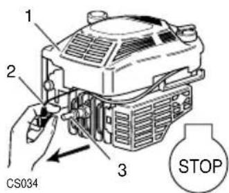
text_image
1 2 CS034 3 STOPSAFETY NOTICE

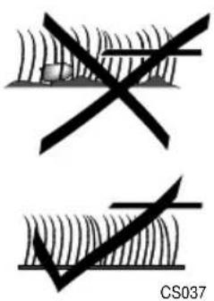
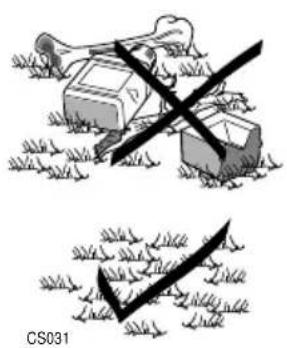
WARNING - PREVENT ACCIDENTS: Before mowing, thoroughly inspect the area where the mower is to be used and remove all objects which when contacted by the mower cutterbar could become dangerous projectiles.
Inspect the area for hidden obstructions which when contacted by the cutterbar could risk health and safety. Remember the location of these obstructions and ensure that you mow around them.
text_image
CS031
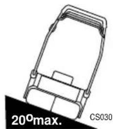
IMPORTANT - PREVENT ENGINE DAMAGE : DO NOT use the mower on a slope greater than 20 degrees.
natural_image
Technical line drawing of a mechanical device with a 20° max. label (no other text or symbols)HEIGHT OF CUT
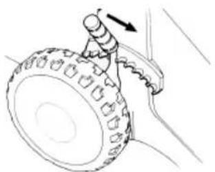
To adjust the height of cut: Grip the lever and pull sideways to disengage it from the locking notch, then push forwards to lower or pull backwards to raise the height of cut. Finally release the lever at the required position and ensure it locks firmly into one of the nine notch settings.
Always select a height of cut to suit operating conditions. Aim to prevent engine overloading and blockages by avoiding low cuts in long grass conditions. Be prepared to make two cuts when the grass is long.
natural_image
Line drawing of a car tire being pulled with a rope, showing motion direction (no text or symbols)TRAVEL
Forward travel:
Push model - Hold and push against the handlebar with both hands to move the mower forwards.
Auto drive models - Hold the handlebar and operate the clutch lever to achieve forward travel.
Release the clutch lever to stop forward travel. When the clutch lever is disengaged the mower can be operated as a push model. This feature is useful when mowing in confined areas.
Reverse travel:
Push models - Hold and pull against the handlebar with both hands to reverse the mower towards you.
Auto drive model - Disengage the clutch lever. Hold and pull against the handlebar with both hands to reverse the mower towards you.

WARNING: PREVENT ACCIDENTS - Always reverse the mower carefully towards you. Always switch off the engine before walking backwards with the mower.
SPEED CHANGE (Code 399S only)
Travel Speed can be altered by selecting one of the four positions.
IMPORTANT: ONLY operate the speed control when the engine is running to avoid damage to the mechanism.

natural_image
Diagram of a hand holding a curved tool with a knob, labeled CS018 (no text or symbols on the diagram itself)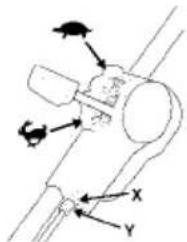
text_image
Diagram showing mechanical or electrical component with labeled arrows and X/Y axesTURNING THE MOWER
To make a wide turn: Steer the mower with the handlebar whilst travelling forward.
To make a tight turn: Stop forward travel. Apply downward pressure on the handlebar to raise the front wheels of the mower just above ground level and steer the mower using the handlebar in the required direction.

WARNING: PREVENT ACCIDENTS - DO NOT raise the front of the mower excessively when making a turn. NEVER raise the rear of the mower when the engine is running.
MOWING WITH GRASS COLLECTION
The grassbag is designed to collect grass clippings.
To achieve best grass collection performance, mow in dry operating conditions.
Recognise that when the grassbag is full the airflow stops and the grassbag deflates.

WARNING: PREVENT ACCIDENTS - ALWAYS check the condition of the grassbag for signs of damage. Replace a damaged grassbag immediately. DO NOT operate the mower with a damaged grassbag. ALWAYS stop the engine and disconnect the spark plug lead before attempting to remove a grass blockage.
Grassbag attachment: Raise the rear deflector and lower the grassbag through the handlebar aperture to connect onto the upper mounting points. Lower the grassbag to rest against the rear of the mower. Finally lower the rear deflector to rest against the top of the grassbag.

text_image
HAYTER CS180Grassbag removal: Raise the rear deflector and lift the grassbag through the handlebar aperture and away from the mower. Finally lower the rear deflector to rest against the rear of the mower.

text_image
HAYTEE CSMBBGrassbag emptying: To empty the grassbag, pour out the grass clippings and shake the grassbag vigorously to clean the airways. Good grass collection depends on good air flow through the grassbag. When collecting grass clippings it is important that the grassbag is emptied regularly to prevent blockages and engine overloading.
OPERATING THE MOWER
1.191.19
MOWING WITHOUT GRASS COLLECTION
To mow without collecting the grass clippings, remove the grassbag and operate the mower with the rear deflector in its lowest position.


WARNING - PREVENT ACCIDENTS: ALWAYS check the condition of the rear deflector for signs of damage and ensure it is positioned correctly on the rear of the mainframe. Replace a damaged rear deflector immediately, never operate the mower with a damaged rear deflector.
HEAVY GROWTH
Areas of heavy growth should be mown without grass collection. If grass collection is required first mow the area without grass collection at the maximum height of cut setting. Allow the grass clippings to dry out and then mow the area at the maximum height of cut setting with the grassbag fitted. Reduce the height of cut and mow the area again as necessary until the required finish is obtained.
MOVING THE MOWER ACROSS NON-GRASSED AREAS
Set the mower to its maximum height of cut to protect the cutting mechanism when moving the mower over surfaces other than grass.

WARNING - PREVENT ACCIDENTS : ALWAYS stop the engine and push the mower carefully at slow walking speed.
CUTTERBAR OPERATION
The cutterbar rotates at the same speed as the engine. The cutterbar will stop within three seconds of the engine being switched off.

WARNING - PREVENTACCIDENTS : DO NOT operate the mower if the cutterbar fails to stop within three seconds. Return the mower to your Hayter dealer for examination and repair.
The cutterbar is driven by the engine via a friction device to help prevent damage occurring to the cutting mechanism when a hidden obstruction or overload is encountered. When the obstruction or overload is removed the friction device will automatically reset.

natural_image
Diagram of a person operating a circular mechanical component with a rotating arrow, surrounded by grass (no text or symbols)
WARNING - PREVENT ACCIDENTS: ALWAYS stop the engine when a hidden obstruction or excessive vibration is encountered. Disconnect the spark plug lead and examine the cutting mechanism. ALWAYS replace a damaged cutterbar - refer to "Maintenance".
MOWING AND GRASS CARE TIPS
In dry weather conditions leave the grass long to help retain ground moisture.
Aerate the lawn to stimulate soil organisms and root growth. In spring and late summer remove dead grass and aerate the lawn by raking or similar means.
Keep the cutterbar sharp. A blunt cutterbar will tear the grass and cause the tips to turn brown.
OPERATING THE MOWER
1.211.2
MOWING AND GRASS CARE TIPS
Continued.
Prevent scalping. Plan your direction of travel to mow across hollows and humps.
Prevent grass damage. Stop forward travel when making a turn.
Prevent grass damage. DO NOT mow in wet conditions.
Brush the lawn surface to disperse worm casts before mowing.
Spike compacted lawn areas with a fork. Fill the holes with sand to improve aeration and drainage.
Mow lawns in a different direction to the previous cut.
As a general rule the grass clippings should be removed each time you mow. If weather conditions are dry and hot and the grass is weed free, leave the clippings on the lawn to help maintain ground moisture.
Mow lawns twice a week when the grass is growing vigorously in the summer.
Mow lawns once a week in spring, autumn and during prolonged dry weather in the summer.
Prevent grass damage - DO NOT remove more than one third of the grass height in one cut.
Recommended grass heights for lawns:-

bar
| Category | Value (mm) | |---|---| | DANGER Grass strength is reduced. | 6 | | Luxury lawn in summer. | 12 | | Luxury lawn in spring, autumn or prolonged dry period. | 19 | | General lawn in summer. | 25 | | General lawn in spring, autumn or prolonged dry period. | 32 | | DANGER Coarse grasses dominate fine grasses. | 38 |MAINTENANCE

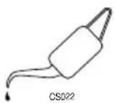
WARNING - PREVENT ACCIDENTS: Stop the engine and disconnect the spark plug lead before attempting to carry out maintenance procedures on the mower.
ENGINE
- Engine Cowl
- Carburettor
- Spark Plug / Lead
- Muffler Guard
- Muffler
- Oil filler Cap/ Dipstick
- Start Grip
- Fuel Cap
- Finger Guard
- Air Cleaner
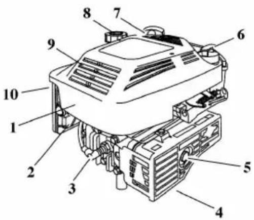
text_image
Labeled diagram of a mechanical device with numbered parts for identificationEngine handbook: For details of engine maintenance refer to the engine operating and maintenance instructions handbook supplied with your mower.
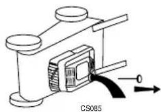
IMPORTANT - Draining engine oil: To drain the engine oil, first drain fuel by operating the engine until the fuel tank is empty and the engine stops. Remove the spark plug lead and allow the engine to cool. Position the mower on its left hand side and ensure that the air cleaner side of the engine is kept uppermost. Remove the oil filler-dipstick to drain the oil.
natural_image
Technical line drawing of a mechanical device labeled CS085, showing components and directional arrows (no readable text or symbols)OIL SERVICE
Refer to the Maintenance Schedule at the end of this section and ensure that the recommendations are followed. More frequent service is required when operating in adverse conditions.
- Check the oil level every 5 hours or daily and ensure that the correct oil level is maintained. Refer to - 'Before Starting the Engine Oil Recommendations' for oil checking procedure and filling instructions.
- Drain the engine oil after the first 5 hours of operation and thereafter at the end of every grass cutting season.
- Change the oil while the engine is warm. Refill with fresh clean oil of the recommended SAE viscosity grade. Refer to - 'Before Starting the Engine: Oil Recommendations'.

WARNING - PREVENT ACCIDENTS: Drain fuel by running the engine until the fuel tank is empty and the engine stops before attempting to tip the mower for oil draining purposes.
- Remove the spark plug lead and allow the engine to cool. Tip the mower over on to its left hand side thus ensuring that the air cleaner is kept uppermost to prevent engine damage. Remove the oil filler dipstick and drain the oil into a suitable container.

text_image
1 2 CS034 3 STOP- Engine
- Spark Plug Lead
- Spark plug
AIR CLEANER SERVICE
Refer to the Maintenance Schedule at the end of this section and ensure that the recommendations are followed. More frequent service is required when operating in adverse conditions.
- Gain access to the cartridge (3) by loosening screw (1) and tilting cover (2).
- Replace the cartridge if very dirty or damaged.
- Clean the cartridge by tapping gently on a flat surface. Do not use petroleum solvents during cleaning as this will cause the cartridge to deteriorate. Do not use pressurised air as this may damage the cartridge. Do not oil the cartridge.
- After servicing the cartridge re-install it in the cover. Insert the tabs on the bottom of the cover into the slots in the bottom of the base (4). Tilt the cover upwards and securely tighten the screw to the base.
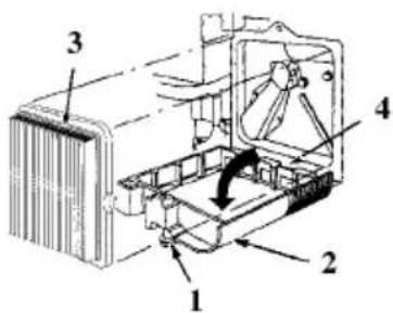
text_image
Technical diagram of an internal combustion engine assembly with numbered components-
Screw
-
Cover
-
Cartridge
-
Base.
GRASSBAG
Remove grass debris from the grassbag immediately after use and check its condition for signs of damage.

WARNING - PREVENT ACCIDENTS: Replace a damaged grassbag immediately.
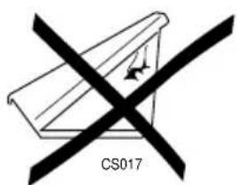
text_image
CS017DECK HOUSING
Remove grass debris from the top and underside of the deck housing immediately after use.
IMPORTANT - PREVENT DAMAGE: Fertilisers and top dressings are particularly corrosive. Thoroughly clean the mower deck immediately after use on treated grass and store well away from corrosive materials.
MAINTENANCE
1.251.2\$
SECURING NUTS AND BOLTS
Regularly check that all securing nuts and bolts are tight. Replace missing or damaged items immediately.

LUBRICATION
Lubricate the wheels, pivot points and linkages with engine oil every 25 operating hours.
Apply a good quality medium grease to the inner control cables at the point of entry and exit from their outer casings.
SPEED CHANGE CABLE
(Code 399S only)
If the speed difference between the settings on the speed change control are judged to be too little or do not exist at all it may be necessary to adjust the cable.
- Run the mower in the 🔍 position for a few minutes.
- If there is any play in the cable by nipple Y the cable must be adjusted. Loosen the locking nut X and adjust the cable by screwing out the nipple Y until the play on the cable is taken up.
- Tighten the locking nut X.
Note! Do not tension the cable more than necessary, it should just sit in the nipple Y without play. Too much cable tension will cause the drive belt to break or result in damage to other parts of the transmission. When adjusting after maintenance (e.g. fitting a new belt) always start with the nipple Y screwed in fully.
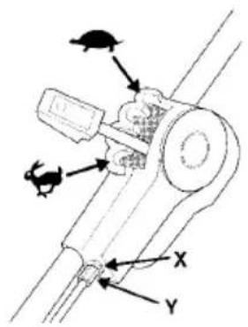
text_image
Diagram of a mechanical device with labeled components X and Y, showing directional arrows and component layout.CLUTCH CABLE ADJUSTMENT
Check the clutch cable operation every 25 operating hours and adjust if necessary. The clutch cable is adjusted correctly when the belt drive just engages with the clutch lever positioned 32-38mm from the handlebar.
Unscrew the lock nuts (1) and screw the adjuster (2) in or out as necessary. Tighten the locknuts (1) when correctly adjusted.
IMPORTANT - PREVENT DAMAGE: ALWAYS operate the mower with the clutch cable correctly adjusted. ALWAYS replace damaged cables.

text_image
32-38mm 1 2 CS019CUTTERBAR

WARNING: PREVENT ACCIDENTS - Never work on the cutterbar unless the spark plug lead has been removed. The cutterbar has sharp edges. ALWAYS wear strong gloves to protect your hands when working on the cutterbar. DO NOT operate tools towards the cutting edges to avoid the risk of injury should the tool slip. ALWAYS use genuine Hayter replacement parts.
The condition of the cutterbar and its mounting arrangement should be checked regularly for signs of wear or damage. Ensure that the cutterbar is not bent or cracked.
A damaged cutterbar that is out of balance will vibrate excessively and may break. DO NOT use an unbalanced cutterbar.
Regularly check that the bolt securing the cutterbar is tightened to the specified torque of 54Nm.
Replace the cutterbar every 2 years or sooner if excessively worn or damaged.
How to remove the cutterbar:
Drain the fuel by operating the engine until the fuel tank is empty and the engine stops. Remove the spark plug lead and allow the engine to cool Turn the mower on its left hand side and ensure that the air cleaner side of the engine is uppermost.
Firmly grip the end of the cutterbar with the gloved hand and remove the bolt and washer securing the cutterbar with a 9/16" A/F spanner.
natural_image
Technical line drawing of a mechanical device with two views (top: cylindrical, bottom: circular), no visible text or symbolsCUTTERBAR
Continued.
How to sharpen and balance the cutterbar: A slightly worn cutterbar may be re-sharpened. Both cutting edges must be sharpened equally to ensure balance. Sharpen the cutterbar every 25 mowing hours or more frequently if conditions require. Remove the cutterbar from the mower and clean using a brush and water. Inspect the cutterbar for signs of damage.
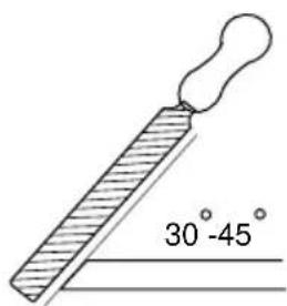
text_image
30°-45°CS040

WARNING - PREVENT ACCIDENTS : DO NOT use a damaged or excessively worn cutterbar.
text_image
CS025Sharpen both cutting edges with a flat file to restore the original cutting edge.
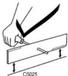
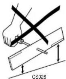
Ensure that the cutterbar is balanced. Use a screw driver with a round shaft to support the cutterbar through its centre hole. Hold the cutterbar horizontal and then release. A balanced cutterbar will remain horizontal. If the cutterbar is not balanced the heavy end will rotate downwards. Sharpen the heavy end until the cutterbar is correctly balanced.
text_image
CS026MAINTENANCE
1.281.28
MAINTENANCE SCHEDULE
Follow the hourly or calendar intervals, whichever occurs first. More frequent service will be required if working for prolonged periods under dusty, dry conditions, or when airborne debris is present or after extensive operation cutting tall, dry grass.
AFTER FIRST 5 HOURS
- Change engine oil
EVERY 5 HOURS OR DAILY
- Check oil level
- Remove grass debris from around engine, muffler/muffler guard and air ways in the top cowl.
- Remove grass debris from top and underside of deck housing.
- Remove grass debris from the grassbag and check for signs of damage.
- Check condition of guards and safety devices.
- Check condition of cutterbar.
EVERY 25 HOURS OR EVERY SEASON
- Change engine oil if continuously operating under heavy load or high ambient temperature.
• Service the air cleaning cartridge.
• Lubricate wheels, pivot points and linkages. - Grease inner control cables at point of entry and exit from their outer casings.
- Check clutch cable adjustment.
- Sharpen cutterbar.
MAINTENANCE
1.291.2
MAINTENANCE SCHEDULE Continued
EVERY 50 HOURS OR EVERY SEASON
- Change engine oil.
EVERY 100 HOURS OR EVERY SEASON
- Clean engine cooling system. Clean more often under dusty conditions or when airborne debris is present or after prolonged operation whilst cutting tall, dry grass.
• Service the air cleaner cartridge. - Replace spark plug.
PREPARING THE MOWER FOR STORAGE
Handlebar storage: To lower the handlebar unscrew the 2 small securing knobs sufficiently to allow it to be pivoted forwards to rest against the mower. Take care to ensure that the control cables do not become snagged at the pivot point and depress the engine stop lever to prevent it being damaged through contact with the engine spark plug.
Storage for periods in excess of 30 days: Engines stored in excess of 30 days need to be protected with Briggs & Stratton fuel additive or drained of fuel to prevent gum from forming in the fuel system or on essential carburettor parts. To ensure your mower is maintained in good working order it is important that the following procedure is adopted. Refer to the Maintenance section as necessary.
Drain fuel from the engine by operating the engine until it stops.
Disconnect the spark plug lead.
Change the engine oil.
natural_image
Diagram of a car with an open trunk and curved arrow indicating motion (no text or symbols)Remove the engine spark plug and pour 15ml of engine oil into the engine cylinder and replace the spark plug. Do not exceed the stated volume of oil as engine damage may occur on re-starting. Do not replace the spark plug lead. Slowly pull the engine start - grip once to crank the engine. This will distribute the oil and help prevent engine corrosion.
Clean grass and debris from the engine cylinder, cylinder head cooling fins, under top cowl, and around and behind muffler/muffler guard.
Clean all other areas of the mower and ensure that the grassbag is clean.
Lubricate the mower.
Treat metal parts with a water repellent anti-corrosion product.
Lower the handlebar, if desired.
Rest the mower deck on wooden blocks to remove the weight of the mower from its wheels/roller.
Cover the mower with a protective sheet and store it in a dry, ventilated area.
FAULT FINDING
1.311.3
FAULT FINDING
| PROBLEM POSSIBLE FAULT REMEDY | ||
| Engine will not turn over Engine stop lever released Operate engine stop leverIncorrect oil level Check oil levelObstruction under deck Remove obstruction | ||
| Engine smokes Excess oil level Check oil levelAir cleaner cartridge oil Service air cleaner soaked or plugged | ||
| Engine runs then stops Fuel | starvation Fill fuel tankFuel cap vent blocked Clean fuel cap vent | |
FAULT FINDING
1.321.32
FAULT FINDING
| REMEDYPROBLEM POSSIB | ||
| Engine will not start. | Engine under load. | Raise height of cut. |
| Fuel starvation. | Fill fuel tank. | |
| Incorrect / contaminated fuel. | Drain fuel tank and fill with correct fuel. | |
| Spark plug lead disconnected. | Connect spark plug lead. | |
| Engine brake not released. | Operate engine stop lever. | |
| Faulty spark plug. | Clean and adjust gap or replace. | |
| Engine runs rough. | Spark plug lead becoming disconnected in use. | Connect spark plug lead. |
| Faulty spark plug. | Clean and adjust gap or replace. | |
| Air cleaner element blocked. | Replace air cleaner element. | |
| Incorrect / contaminated fuel. | Drain fuel tank and fill with correct fuel. | |
| Engine vibrates excessively. | Mounting bolts loose. | Tighten bolts. |
| Cutterbar bolt loose. | Tighten bolt. | |
| Cutterbar out of balance. | Balance cutterbar. | |
| Uneven cut. | Undulating ground contours. | Change direction of travel. |
| Cutterbar worn. | Sharpen the cutterbar. | |
| Cutterbar out of balance. | Balance cutterbar. | |
| Wheels damaged. | Inspect and replace as necessary. |
FAULT FINDING
1.331.3\$
FAULT FINDING
Continued.
| POSSIBLE FAULT | REMEDYPROBLEM | |
| Discharge chute blocks. | Grass is wet.Cut height too low.Grassbag full.No airflow through the grassbag. | Mow dry grass.Increase cut height.Empty grassbag.Clean the grassbag. |
| Mower is hard to push. | Height of cut too low.Wheels damaged. | Increase height of cut.Inspect and lubricate or replace as necessary. |
| Mower will not self propel.(Auto drive model only). | Clutch out of adjustment.Drive belt damaged. | Adjust clutch lever.Replace drive belt. |
| Poor grass collection. | No airflow through the grassbag.Discharge chute blocked.Wet grass.Grassbag full. | Clean the grassbag.Remove blockage.Mow dry grass.Empty grassbag. |
PARTS LIST
| ITEM NO. | DESCRIPTION | PART NO. | QTY. | ||
| 397S | 398S | 399S | |||
| 1 Mainframe - 48 397039V 1 1 0Mainframe - 53 399020V 0 0 12 Height Adjust Quadrant 397028 1 1 13 Cover - Black 397037 1 1 0Cover - Black 399019 0 0 14 Engine-B+S Quantum XTL45 397007 1 1 15 Decal - Engine 397008 1 1 0Decal - Engine 399008 0 0 16 Key Woodruff 1662 1 1 17 Nut-UNC 1/4" Plain 09197 2 2 28 Knob 397046 2 2 2 | |||||
| 9 Washer | 09475 | 2 | |||
| 10 | Screw - Plastite | 09765 | 10 | 10 | 11 |
| 11 | Screw - Taptite | 09596 | 16 | 16 | 18 |
| 12 | Wheel Assembly | 397021 2 2 0 | |||
| Wheel Assembly | 399009 0 0 2 | ||||
| 13 | Handlebar - Lower RH | 397004W | 1 1 1 | ||
| 14 | Handlebar - Lower LH | 307003W | 1 1 1 | ||
| 15 | Knob - M8 Handlebar | 480088 2 2 2 | |||
| 16 | Guide Rope | 305127 1 1 1 | |||
| 17 | Bolt - Handlebar | 226024 2 2 2 | |||
| 18 | Plug - Tube | 300160 2 2 2 | |||
| 19 | Cable Tie | 3966 3 3 3 | |||
| 20 | Nut | 09544 | 1 | ||
| 21 | Washer - Plain | 09472 | 1 1 1 | ||
| 22 | Guide Rope | 305093 1 1 1 | |||
| 23 | Throttle Control & OPC Assemble | 397010 1 1 0 | |||
| Throttle Control & OPC Assemble | 480093 0 0 1 | ||||
| 24 | Screw - Detite Posi Pan | 09600 | 2 | 2 | 2 |
| 25 | Pin Pivot | 340182 2 2 2 | |||
| 26 | Lever Engine | 340179 1 1 1 | |||
| 27 | Washer - Nylon | 09688 | 6 2 2 | ||
| 28 | Screw - PT Pan Flange | 09687 | 2 | 2 | 2 |
| 29 | Upper Handlebar | 340183W | 1 1 0 | ||
| Upper Handlebar | 399026W | 0 0 1 | |||
| 30 | Frame - Grassbag W/A | 397007W | 1 1 0 | ||
| Frame - Grassbag W/A | 399005W | 0 0 1 | |||
| 31 | Fabric Grassbag | 397006 1 1 0 | |||
| Fabric Grassbag | 399006 0 0 1 | ||||
| 32 | Flap - Black | 397024 1 1 1 | |||
| 33 | Spring | 397025 1 1 1 | |||
PARTS LIST Continued.
| ITEM NO. | DESCRIPTION | PART NO. | QTY. | ||
| 397S | 398S | 399S | |||
| 34 Flap Attachment - Black 397026 1 1 1 | |||||
| 35 Attachment - RH 397036 1 1 1 | |||||
| 36 Attachment - LH 397035 1 1 1 | |||||
| 37 Battery Holder 397034 1 1 1 | |||||
| 38 Grip Fix 09773 2 0 0 | |||||
| 39 Rear Attachment 397027 1 1 1 | |||||
| 40 Bolt - Coach 09766 2 2 2 | |||||
| 41 Attachment Plate 397018 2 2 2 | |||||
| 42 Spring 397033 1 1 1 | |||||
| 43 Handlebar Attachment | 397017 2 2 2 | ||||
| 44 Screw -Taptite | 09546 2 2 2 | ||||
| 45 Wheel Cover | 397023 2 0 0 | ||||
| Cover Plate | 398003 0 2 2 | ||||
| 46 Screw - M8 x 20 | 09368 2 2 2 | ||||
| 47 Height Adjustment Lever | 397031 1 1 1 | ||||
| 48 Bushing | 397016 2 2 2 | ||||
| 49 Seal Shaft | 397041 2 2 2 | ||||
| 50 Screw - Taptite | 09349 3 3 3 | ||||
| 51 Friction Disc W/A | 397042W | 1 1 1 | |||
| 52 Cutterbar 19" | 480149 1 1 0 | ||||
| Cutterbar 21" | 330032 0 0 1 | ||||
| 53 Piece Cutterbar Distance | 216008 1 1 0 | ||||
| Piece Cutterbar Distance | 4014 | 0 0 1 | |||
| 54 Washer - Spring | 09273 1 1 1 | ||||
| 55 Screw | 09116 | 1 | |||
| 56 Front Axle | 397029 1 1 1 | ||||
| 57 Height Adjustment Rod | 397038 1 1 0 | ||||
| Height Adjustment Rod | 399021 0 0 1 | ||||
| 58 Rear Axle | 397030 1 1 1 | ||||
| 59 Grip Fix | 09772 2 2 2 | ||||
| 60 Retainer | 397013 2 2 2 | ||||
| 61 Lever Knob | 397032 1 1 1 | ||||
| 62 Spring 397012 2 2 2 | |||||
| 63 Wheel Cover | 397015 2 2 2 | ||||
| 64 Bearing Kit | 397045 4 4 2 | ||||
| 65 Wheel Assembly - (Incl. item 64) | 397014 2 2 2 | ||||
| 66 Washer | 09263 | 10 | 10 | 12 | |
| 67 Spring 397019 2 2 2 | |||||
| 68 Hub Cap - Black | 397020 2 2 2 | ||||
| 69 Hub Cap - Black | 397022 2 2 0 | ||||
| Hub Cap - Black | 399010 0 0 2 | ||||
PARTS LIST Continued.
| ITEM NO. | DESCRIPTION | PART | NO.397S 398S 399S | |
| 70 Shaft 397040 1 0 0 | ||||
| 71 Transmission 398001 0 1 1 | ||||
| 72 Washer 02575 0 4 4 | ||||
| 73 Drive Key 398004 0 2 2 | ||||
| 74 Pin | 398002 | 0 | 2 | |
| 75 Lock Washer | 398005 0 2 2 | |||
| 76 Gear Wheel | 398007 0 2 2 | |||
| 77 Support Washer | 398006 0 2 2 | |||
| 78 Lever Clutch | 306094 0 1 1 | |||
| 79 Clip E | 09767 0 2 2 | |||
| 80 Tension Spring | 398008 | 0 | 1 | |
| Bracket | 399022 0 0 1 | |||
| 81 V Belt | 398011 | 0 1 0 | ||
| V Belt | 399024 0 0 1 | |||
| 82 Belt Pulley | 398010 0 1 0 | |||
| Variator Assy | 399018 0 0 1 | |||
| 83 Pin Roll | 09770 0 1 0 | |||
| Pin Roll | 09771 0 0 1 | |||
| 84 Grubscrew | 09769 0 1 1 | |||
| 85 Bush | 398012 0 1 0 | |||
| Engine Spacer | 399025W | 0 0 1 | ||
| 86 Engine Belt Pulley | 398009 0 1 0 | |||
| Engine Belt Pulley | 399012 0 0 1 | |||
| 87 Bracket Cable Clutch | 306108 0 1 1 | |||
| 88 Cable Clutch | 397009 0 1 1 | |||
| 89 Ball Bearing | 399027 0 0 2 | |||
| 90 Knob | 399016 0 0 1 | |||
| 91 Screw Plastite | 09768 0 0 2 | |||
| 92 Variator Control | 399017 0 0 1 | |||
| 93 Attachment | 399013 0 0 1 | |||
| 94 Screw Taptite | 09764 0 0 1 | |||
| 95 Spacer | 399011 | 0 0 1 | ||
| 96 Tension Roller | 399015 0 0 1 | |||
| 97 Tension Arm | 399023 0 0 1 | |||
| 98 Belt Pulley | 399014 0 0 1 | |||
| 99 Bolt | 09547 0 0 1 | |||
| 100 Decal - Hayter | 533005 1 1 1 | |||
| 101 Decal - Engine Stop | 331046 1 1 1 | |||
| 102 Decal - Height of Cut | 320006 1 1 1 | |||
| 103 Decal - Caution | 219189 1 1 1 | |||
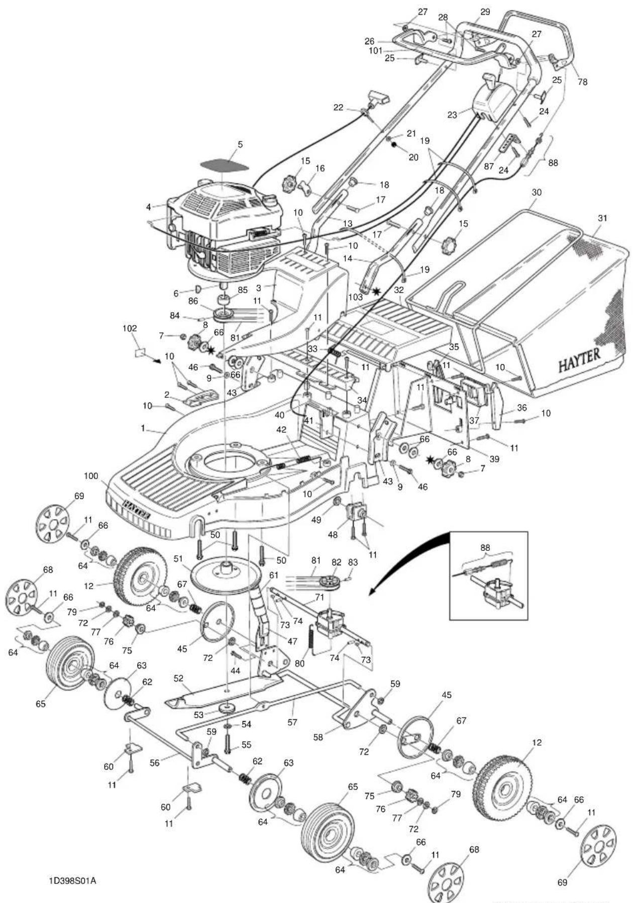
397S PARTS LIST

text_image
Technical diagram of a HAYTER robotic lawn mower with numbered components and labeled parts398S PARTS LIST
2.52.5
text_image
Technical diagram of a HAYTER robotic lawn system with numbered components and labeled parts397011MA260599A

text_image
Technical diagram of a HAYTER robotic arm with numbered components and labeled parts, including a detailed inset view.ENGINE ANCILLARY PARTS
2.72.7
These parts are available through an authorised Briggs & Stratton dealer.
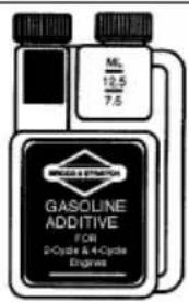
text_image
ML 12.5 7.5 BRINJES & STRUMENTS GASOLINE ADDITIVE F/CR 2-Cycle & 4-Cycle EngineP/N 5041
999005E
FUEL ADDITIVE

992030
AIR CLEANER CARTRIDGE

text_image
Air Cleaner Cartridge 491588SPARK PLUG

802592E
SPARK PLUG WRENCH

natural_image
Line drawing of a mechanical tool or bracket with a handle and base (no text or symbols)\$98.38
SPARK PLUG TESTER

natural_image
Mechanical component diagram with no visible text or symbolsAbout Your Engine Warranty
Briggs & Stratton welcomes warranty repair and apologizes to you for being inconvenienced. Any Authorized Service Dealer may perform warranty repairs. Most warranty repairs are handled routinely, but sometimes requests for warranty service may not be appropriate. For example, warranty would not apply if engine damage occurred because of misuse, lack of routine maintenance, shipping, handling, warehousing or improper installation. Similarly, warranty is void if the serial number of the engine has been removed or the engine has been altered or modified.
If a customer differs with the decision of the Service Dealer, an investigation will be made to determine whether the warranty applies. Ask the Service Dealer to submit all supporting facts to his Distributor or the Factory for review. If the Distributor or the Factory decides that the claim is justified, the customer will be fully reimbursed for those items that are defective. To avoid misunderstanding which might occur between the customer and the Dealer, listed below are some of the causes of engine failure that the warranty does not cover.
Improper maintenance:
The life of an engine depends upon the conditions under which it operates, and the care it receives. Some applications, such as tillers, pumps and rotary mowers, are very often used in dusty or dirty conditions, which can cause what appears to be premature wear. Such wear, when caused by dirt, dust, spark plug cleaning grit, or other abrasive material that has entered the engine because of improper maintenance, is not covered by warranty.
This warranty covers engine related defective material and/or workmanship only, and not replacement or refund of the equipment to which the engine may be mounted. Nor does the warranty extend to repairs required because of:
-
PROBLEMS CAUSED BY PARTS THAT ARE NOT ORIGINAL BRIGGS & STRATTON PARTS.
-
Equipment controls or installations that prevent starting cause unsatisfactory engine performance, or shorten engine life. (Contact equipment manufacturer.)
-
Leaking carburetors, clogged fuel pipes, sticking valves, or other damage, caused by using contaminated or stale fuel. (Use clean, fresh, lead-free gasoline and Briggs & Stratton gasoline stabilizer, Part No. 5041.)
-
Parts which are scored or broken because an engine was operated with insufficient or contaminated lubricating oil, or an incorrect grade of lubricating oil (check oil level daily or after every 8 hours of operation. Refill when necessary and change at recommended intervals.) Read "Owner's Manual."
-
Repair or adjustment of associated parts or assemblies such as clutches, transmissions, remote controls, etc., which are not manufactured by Briggs & Stratton.
-
Damage or wear to parts caused by dirt, which entered the engine because of improper air cleaner maintenance, re-assembly, or use of a non-original air cleaner element or cartridge. (At recommended intervals, clean and re-oil the Oil
Foam® element or the foam pre-cleaner, and replace the cartridge.) Read "Owner's Manual."
7. Parts damaged by over-speeding, or overheating caused by grass, debris, or dirt, which plugs or clogs the cooling fins, or flywheel area, or damage caused by operating the engine in a confined area without sufficient ventilation. (Clean fins on the cylinder, cylinder head and flywheel at recommended intervals.) Read "Owner's Manual."
8. Engine or equipment parts broken by excessive vibration caused by a loose engine mounting, loose cutter blades, unbalanced blades or loose or unbalanced impellers, improper attachment of equipment to engine crankshaft, over-speeding or other abuse in operation.
9. A bent or broken crankshaft, caused by striking a solid object with the cutter blade of a rotary lawn mower, or excessive v-belt tightness.
10. Routine tune-up or adjustment of the engine.
11. Engine or engine-component failure, i.e., combustion chamber, valves, valve seats, valve guides, or burned starter motor windings, caused by the use of alternate fuels such as, liquified petroleum, natural gas, altered gasolines, etc.
Warranty is available only through service dealers which have been authorized by Briggs & Stratton Corporation, your nearest Authorized Service Dealer is listed in the "Yellow Pages™" of your telephone directory under "Engines, Gasoline" or "Gasoline Engines," "Lawn Mowers," or similar category.
Briggs & Stratton Engine Owner Warranty Policy
Effective February 1, 1994, replaces all undated Warranties and all Warranties dated before February 1, 1994
LIMITED WARRANTY
Briggs & Stratton Corporation will repair or replace, free of charge, any part, or parts of the engine that are defective in material or workmanship or both. Transportation charges on parts submitted for repair or replacement under this Warranty must be borne by purchaser. This warranty is effective for the time periods and subject to the conditions provided for in this policy. For warranty service contact your nearest Authorized Service Dealer as listed in the "Yellow Pages™ under Engines, Gasoline," Gasoline Engines, Lawn Mowers' or similar category. THERE IS NO OTHER EXPRESS WARRANTY. IMPLIED WARRANTIES, INCLUDING THOSE OF MERCHANTABILITY AND FITNESS FOR A PARTICULAR PURPOSE ARE LIMITED TO ONE YEAR FROM PURCHASE OR TO THE EXTENT PERMITTED BY LAW ANY AND ALL IMPLIED WARRANTIES ARE EXCLUDED. LIABILITY FOR CONSEQUENTIAL DAMAGES UNDER ANY AND ALL WARRANTIES ARE EXCLUDED TO THE EXTENT EXCLUSION IS PERMITTED BY LAW. Some states do not allow limitations on how long an implied warranty lasts, and some states do not allow the exclusion or limitation of incidental or consequential damages, so the above limitation and exclusion may not apply to you. This warranty gives you specific legal rights and you may also have other rights which vary from state to state."
Bridgs & Stratton Corporation

Chairman and Chief Executive Officer
WARRANTY PERIOD
| ENGINES | WITHIN U.S.A. AND CANADA | OUTSIDE U.S.A. AND CANADA | ||
| CONSUMER USE* | COMMERCIAL USE* | CONSUMER USE* | COMMERCIAL USE* | |
| All VanguardTM engines. | 2 year - engine / Lifetime** - Magnetron® ignition | |||
| All Diamond Plus®, EuropaTM, Industrial PlusTM and all I/C®. | 2 year | 1 year | 2 year | 1 year |
| Quantum® and Diamond Power®. | 2 year | 90 days | 2 year † | 90 days |
| All standard 2 through 18 HP engines installed on lawn mowers, riders,edgers, chippers, shredders, tillers, and all Sno/Gard engines. | 2 year | 90 days | 1 year | 90 days |
| All other standard 2 through 18 HP engines. | 1 year | 90 days | 1 year | 90 days |
For purposes of this warranty policy, "consumer use" means personal residential household use by the original retail consumer. "Commercial use" means all other uses, including use for commercial, income producing or rental purposes. Once an engine has experienced commercial use, it shall thereafter be considered as a commercial use engine for purposes of this warranty. Engines used in competitive racing or on commercial or rental tracks are not warranted.
Lifetime limited warranty of the Magnetron® ignition covers parts and labor for the first five (5) years from the date of purchase; thereafter only parts. "Lifetime" means lifetime of the engine in the hands of the original purchaser.
† One (1) year in Australia, New Zealand, Middle East and Africa.
NO WARRANTY REGISTRATION CARD IS NECESSARY TO OBTAIN WARRANTY ON BRIGGS & STRATTON ENGINES.
YOU MUST SAVE THE PURCHASE RECEIPT. A PROOF OF PURCHASE DATE WILL BE REQUIRED TO OBTAIN WARRANTY.
| Briggs & Stratton Engines Are Made Under One Or More Of The Following Patents: Design D-247,177 (Other Patents Pending) | |||||||||
| 5.320.796 | 5.285.700 | 5.197.422 | 5.105.331 | 5.040.503 | 4.995.357 | 4.895.119 | 4.520.288 | 4.355.253 | 4.168.288 DES. 308.872 |
| 5.271.383 | 5.243.878 | 5.191.864 | 5.086.890 | 5.016.588 | 4.977.879 | 4.819.593 | 4.453.507 | 4.270.509 | DES. 309.458 DES. 308.871 |
| 5.269.713 | 5.197.425 | 5.150.674 | 5.040.644 | 4.996.956 | 4.971.219 | 4.694.792 | 4.430.984 | 4.233.534 | DES. 309.457 |
2.9
NOTES
2.9
CUSTOMER INFORMATION
2.102.10
Machine Serial No.:
Engine Serial No.: