FEX-SN-M02202021 - Security Camera Bolin Technology - Free user manual and instructions
Find the device manual for free FEX-SN-M02202021 Bolin Technology in PDF.

User questions about FEX-SN-M02202021 Bolin Technology
0 question about this device. Answer the ones you know or ask your own.
Ask a new question about this device
Download the instructions for your Security Camera in PDF format for free! Find your manual FEX-SN-M02202021 - Bolin Technology and take your electronic device back in hand. On this page are published all the documents necessary for the use of your device. FEX-SN-M02202021 by Bolin Technology.
USER MANUAL FEX-SN-M02202021 Bolin Technology
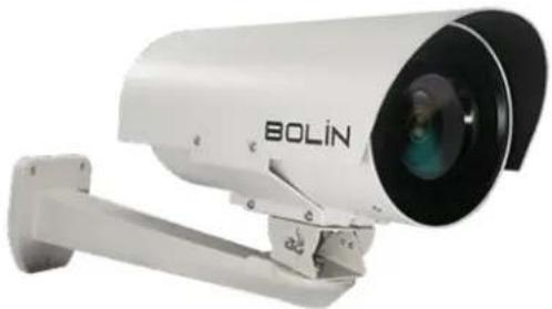
FEX SERIES FIXED FHD SDI + IP ZOOM CAMERA
USER MANUAL PART ONE
VERSION: FEX-SN-M02202021
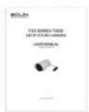
natural_image
Exterior view of a white BOLiN security camera with mounted sensor and camera lens (no text or symbols visible on body)Contents
IMPORTANT INFORMATION .... 3
OVERVIEW 6
KEY FEATURES(B-CLASS)......6
WHAT'S IN THE BOX....7
ACCESSORIES (OPTIONAL) 7
CAMERA DIAGRAMS......8
INSTALLING YOUR CAMERA....9
RJ45 WATER-RESISTANT CONNECTOR INSTALLATION GUIDE....9
MAKE THE RJ45 CONNECTOR 10
MAKE THE RS422 CONTROL CONNECTOR....11
MAKE THE BNC SDI VIDEO CONNECTOR 11
MAKE THE 12VDC POWER CONNECTOR .... 12
CABLE REQUIREMENTS 12
INSTALL THE TAIL CABLE....13
MOUNTING THE CAMERA....13
POWER CONNECTION 13
CONTROL CONNECTION....14
RS422 (VISCA) CONNECTION 14
PELCO P/D KEYBOARD RS485 CONNECTION 18
VISCA OVER IP CONTROL 21
VISCA OVER IP NETWORK CONFIGURATION 21
SETUP CAMERA ID, BAUD RATE AND CONTROL PROTOCOL....23
ADJUSTING AND SETTING WITH MENUS 24
EXPOSURE MENU 25
WHITE BALANCE MENU....26
PICTURE MENU 27
LENS PARAMETERS MENU....28
SYSTEM SETUP MENU 29
VIDEO FORMAT: SDI + IP TRUE DUAL OUTPUT: 30
USE IP VIDEO OUTPUT 34
SETTING CAMERA OVER THE LAN 34
ACCESSING YOUR CAMERA....34
Operating Instructions
Thank you for purchasing our product. If there are any questions, please contact the authorized dealer.
Before operating the unit, please read this manual thoroughly and retain it for future reference.
Copyright
Copyright 2015-2021 Bolin Technology all rights reserved. No part of this manual may be copied, reproduced, translated, or distributed in any form or by any means without prior consent in writing from our company.
Trademark Acknowledgement
BOLIN TECHNOLOGY
BOLIN TECHNOLOGY and other Bolin's trademarks and logos are the property of Bolin Technology. Other trademarks, company names and product names contained in this manual are the property of their respective owners.
Trademarks and Registered Trademarks Acknowledgement
- Microsoft, Windows, ActiveX, and Internet Explorer are registered trademarks of Microsoft Corporation in the U.S. and/or other countries.
- HDMI, the HDMI logo and High-Definition Multimedia Interface are the trademarks or registered trademarks of HDMI Licensing, LLC in the United States and other countries.
- The Software may contain h.264/AVC video technology, the use of which requires the following notice from MPEG-LA, L.L.C.:
THIS SOFTWARE IS LICENSED UNDER THE AVC PATENT PORTFOLIO LICENSE FOR THE PERSONAL AND NON-COMMERCIAL USE OF A CONSUMER TO (I) ENCODE VIDEO IN COMPLIANCE WITH THE AVC STANDARD ("AVC VIDEO") AND/OR (II) DECODE AVC VIDEO THAT WAS ENCODED BY A CONSUMER ENGAGED IN A PERSONAL AND NON-COMMERCIAL ACTIVITY AND/OR WAS OBTAINED FROM A VIDEO PROVIDER LICENSED TO PROVIDE AVC VIDEO. NO LICENSE IS GRANTED OR SHALL BE IMPLIED FOR ANY OTHER USE. ADDITIONAL INFORMATION MAY BE OBTAINED FROM MPEG LA, L.L.C. SEE http://www.mpegla.com.
• HEVC/h.265 Covered by one or more claims of patents listed at patentlist.hevcadvance.com
- HDBaseT is a trademark of the HDBaseT Alliance.
- ONVIF trademarks and logos are to be used per the guidelines established in this and other ONVIF policies and documents including the ONVIF Rules of Membership and the ONVIF Logo Guidelines1.
- Other trademarks, company names and product names contained in this manual are the property of their respective owners.
IMPORTANT INFORMATION
Legal Notice
Attention:
To ensure account security, please change the password after your first login. You are recommended to set a strong password (no less than eight characters).
The contents of this document are subject to change without prior notice. Updates will be added to the new version of this manual. We will readily improve or update the products or procedures described in the manual.
Best effort has been made to verify the integrity and correctness of the contents in this document, but no statement, information, or recommendation in this manual shall constitute formal guarantee of any kind, expressed or implied. We shall not be held responsible for any technical or typographical errors in this manual.
The product appearance shown in this manual is for reference only and may be different from the actual appearance of your device. This manual is a guide for multiple product models and so it is not intended for any specific product.
In this manual, the illustrations of displayed interface, parameters displayed, drawings and value ranges may vary with models.
Please see the actual product for details.
Due to uncertainties such as physical environment, discrepancy may exist between the actual values and reference values provided in this manual.
Use of this document and the subsequent results shall be entirely on the user's own responsibility.
Disclaimer
CAUTION!
The default password is used for your first login. To ensure account security, please change the password after your first login. You are recommended to set a strong password (no less than eight characters).
- To the maximum extent permitted by applicable law, the product described, with its hardware, software, firmware and documents, is provided on an “as is” basis.
- Best effort has been made to verify the integrity and correctness of the contents in this manual, but no statement, information, or recommendation in this manual shall constitute formal guarantee of any kind, expressed or implied. We shall not be held responsible for any technical or typographical errors in this manual. The contents of this manual are subject to change without prior notice. Update will be added to the new version of this manual.
- Use of this manual and the subsequent result shall be entirely on the user's own responsibility. In no event shall we be liable to you for any special, consequential, incidental, or indirect damages, including, among others, damages for loss of business profits, business interruption, or loss of data or documentation in connection with the use of this product.
- Video and audio surveillance can be regulated by laws that vary from country to country. Check the law in your local region before using this product for surveillance purposes. We shall not be held responsible for any consequences resulting from illegal operations of the device.
- The illustrations in this manual are for reference only and may vary depending on the version or model. The screenshots in this manual may have been customized to meet specific requirements and user preferences. As a result, some of the examples and functions featured may differ from those displayed on your monitor.
• This manual is a guide for multiple product models and so it is not intended for any specific product. - Due to uncertainties such as physical environment, discrepancy may exist between the actual values and reference values provided in this manual. The ultimate right to interpretation resides in our company.
Environmental Protection
This product has been designed to comply with the requirements on environmental protection. For the proper storage, use and disposal of this product, national laws and regulations must be observed.
Symbols
The symbols in the following table may be found in this manual. Carefully follow the instructions indicated by the symbols to avoid hazardous situations and use the product properly.
WARNING! : Indicates a hazardous situation which, if not avoided, could result in bodily injury or death.
CAUTION!: Indicates a situation which, if not avoided, could result in damage, data loss or malfunction to product.
NOTE: Indicates useful or supplemental information about the use of product.
Safety Information
WARNING!
Installation and removal of the unit and its accessories must be carried out by qualified personnel. You must read all of the Safety Instructions supplied with your equipment before installation and operation.
Warnings:
- If the product does not work properly, please contact your dealer. Never attempt to disassemble the camera yourself. (We will not assume any responsibility for problems caused by unauthorized repair or maintenance.)
• This installation should be made by a qualified service person and should conform to all the local codes. - When shipping, the camera should be packed in its original packaging.
• Make sure the power supply voltage is correct before using the camera. - Do not drop the camera or subject it to physical shock.
- Do not touch sensor modules with fingers. If cleaning is necessary, use a clean cloth with a bit of ethanol and wipe it gently. If the camera will not be used for an extended period of time, put on the lens cap to protect the sensor from dirt.
Maintenance Precautions:
- If there is dust on the front glass surface, remove the dust gently using an oil-free brush or a rubber dust blowing ball.
- If there is grease or a dust stain on the front glass surface, clean the glass surface gently from the center outward using anti-static gloves or an oil-free cloth. If the grease or the stain still cannot be removed, use anti-static gloves or an oil-free cloth dipped with detergent and clean the glass surface gently until it is removed.
- Do not use organic solvents, such as benzene or ethanol when cleaning the front glass surface.
Regulatory Compliance
FCC Part 15
This equipment has been tested and found to comply with the limits for digital device, pursuant to part 15 of the FCC Rules. These limits are designed to provide reasonable protection against harmful interference when the equipment is operated in a commercial environment. This equipment generates, uses, and can radiate radio frequency energy and, if not installed and used in accordance with the instruction manual, may cause harmful interference to radio communications. Operation of this equipment in a residential area is likely to cause harmful interference in which case the user will be required to correct the interference at his own expense.
This product complies with Part 15 of the FCC Rules. Operation is subject to the following two conditions:
This device may not cause harmful interference.
This device must accept any interference received, including interference that may cause undesired operation.

LVD/EMC Directive
This product complies with the European Low Voltage Directive 2006/95/EC and EMC Directive 2004/108/EC.

WEEE Directive-2002/96/EC
The product this manual refers to is covered by the Waste Electrical & Electronic Equipment (WEEE) Directive and must be disposed of in a responsible manner.
Overview
This user guide is suitable for the following models:
If the model numbers that have following letter included in the end, means some extra features included:
○ B Class – Use for broadcasting, SDI video format 1080P and 1080I supported, frame rate up to 60/59.94. It supports not only PELCO D/P, IP ONVIF but also VISCA and VISCA OVER IP control.
- S Class – Use for video surveillance or other applications, SDI video format 1080P and 720P supported, frame rate up to 60. It supports PELCO D/P and IP ONVIF control.
• FEX30SHD-B-RSNP2 (FHD, SDI+IP, B-Class)
• FEX30SHD-S-RSNP2 (FHD, SDI+IP, S-Class) (Special Order Only)
Key Features(B-Class)
- Video Output: SDI+IP, True Dual-Output SDI+IP Simultaneously, It outputs IP 1080p60/30 when SDI is set to either 1080p60/30 or 1080i59.94/29.97.
• Supports Various Resolutions:
○ IP: Up to 1080P60
o SDI: Up to 1080p60 and 1080i59.94
- Zoom: 30X
• Video Compression: H.264/H.265/MJPEG
• RS485/RS422 Communication, Auto compatible with PELCO D and VISCA Protocol
- Store image parameter (zoom, iris, white balance, exposure, picture setting) to a specified preset
- 120dB true WDR
- Image Stabilizer
- Various Image Functionalities: WDR, Defog, Day/Night
• Outdoor Environmental Rating: IP68, water-resistant Connector, Faceplate heater
- Nitrogen Pressurized Housing, Corrosion Resistant Treatment Housing, Sunshield equipped.
- Wide operating temperature range, -40°C to 65°C continuous, up to 70°C for 12 hours.
- Operating Humidity: 100% suitable for use
- Input Power: POE (IEEE802.3at), 12VDC
• IP supports ONVIF Profile 2.4 compliant and VISCA OVER IP control
• Infrared LED, Illumination up to 50 meters (Optional)
• Supports 255 Presets
• Built-in electrical transient/surge protection
• MS connector on housing with detachable 5ft long Tail-cable water resistant RJ45/Power/RS422/BNC connector
- Mounting plate for standard bracket use.
WHAT'S IN THE BOX
Camera X 1
Pigtail cable with connectors and RJ45 waterproof couplers

Hex Key Wrench 0.9 X 1
A set of screws X 1
User Manual X 1
Accessories (Optional)
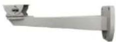
FEX-WM-A
Aluminum alloy wall mount bracket
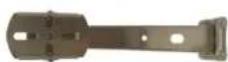
FEX-WM-S
Stainless steel wall mount bracket
Camera Diagrams
Camera
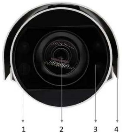
natural_image
Cross-sectional view of a camera lens with numbered parts (1–4), showing internal structure and no text or symbols beyond labels.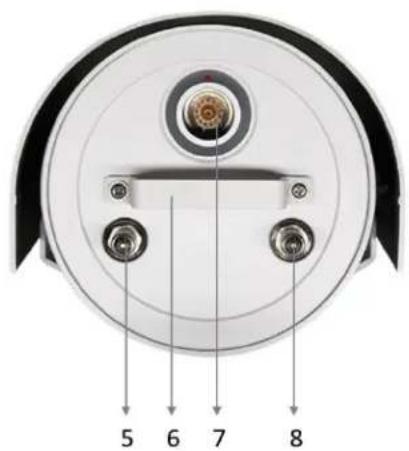
text_image
5 6 7 8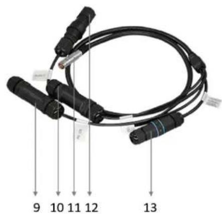
text_image
9 10 11 12 13- Infrared LED Lights
- Camera Lens, 30X zoom
- Infrared LED Lights
- Sunshield
- Nitrogen Pressurization Schrader Valve (For Factory Use Only)
- Handle
- MS Connector (Male), SDI+IP+12VDC+POE+RS422 connection.
- Nitrogen Pressurization Schrader Valve (For Factory Use Only)
- Pigtail cable: SDI BNC connector with water-resistant Coupler
- Pigtail cable: 12VDC power connector (5.5x2.1mm Jack) with water-resistant Coupler
- Pigtail cable: MS Connector (Female) connect to the camera.
- Pigtail cable: RJ45 connector (POE IEEE802.3at) with water-resistant Coupler
- Pigtail cable: RS422 connector with water-resistant Coupler
Installing Your Camera
NOTE:
- The camera is completely sealed with pressurized nitrogen inside.
- Do not open your camera nor release the Nitrogen air from the Schrader Valves without authorization from a BOLIN Technology Support representative
- Opening the camera and / or releasing the nitrogen from inside the it may damage the camera. This will void the warranty.
• The diagrams included in this user guide are for reference only. See the actual product to install and mount your camera.
The pigtail cable is detachable. It includes:
- RJ45 connector for IP video streaming and POE power
- RS422/RS485 connector for serial control
- 12VDC injector for power
- BNC connector for SDI video signal output
- Four sets of water-resistant couplers for the connectors
Please follow the instruction below to install the connectors and water-resistant couplers correctly.
RJ45 Water-resistant Connector Installation Guide
The RJ45 connector is IP67 water-resistant rated. Please follow the illustration bellow to install the connector.
- POE-ready Ethernet Port (Built with water Resistant Coupler)
- RJ45 Head
- Ethernet Cable (CAT5e/ CAT6)
- Silicone Ring
- Paw
- Silica Gel Pad
-
Cap
-
Insert the Ethernet cable through the water-resistant head kit (parts 4, 5, 6 and 7)
- Terminate the cable to an RJ45 head
- Insert the RJ45 head into the Ethernet port
- Tighten the head kits (parts 4, 5, 6 and 7)

text_image
1 2 3 4 5 6 7NOTE:
Please install the connector properly as the following picture:
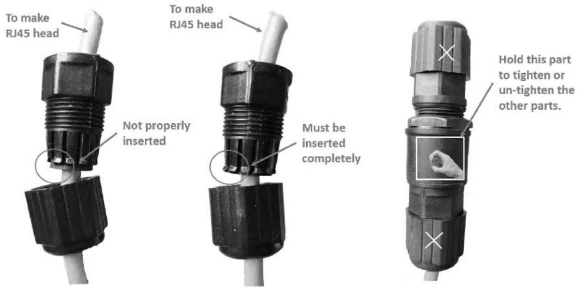
text_image
To make RJ45 head Not properly inserted To make RJ45 head Must be inserted completely Hold this part to tighten or un-tighten the other parts.NOTE:
The connector that has been installed properly should be like the picture below:
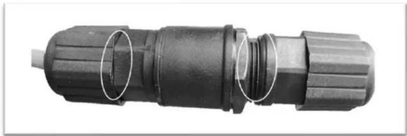
natural_image
Close-up of a black plastic electrical connector with two white oval highlights (no text or symbols visible)Make the RJ45 connector

flowchart
graph TD
    A["Internal Connector"] --> B["Insert Properly & Strongly Tighten"]
    B --> C["Internal Connector"]
    C --> D["Internal Connector"]
    D --> E["Internal Connector"]
    E --> F["Internal Connector"]
    style A fill:#f9f,stroke:#333
    style B fill:#ccf,stroke:#333
    style C fill:#cfc,stroke:#333
    style D fill:#fcc,stroke:#333
    style E fill:#cff,stroke:#333
RJ45 Connector + Waterproof Coupler Installation
Make the RS422 control connector

text_image
1 TX+ 2 TX- 3 RX+ 4 RX- 5 GND 1 2 3 4 5 Open Side for Wiring Pre-Wired inside of the coupler 1 TX+ Red 2 TX- Purple 3 RX+ Green 4 RX- Grey 5 GND Yellow Insert properly and Strongly TightenRS422 Connector + Waterproof Coupler Installation
Make the BNC SDI video connector

text_image
Insert properly and Strongly TightenBNC Video Connector + Waterproof Coupler Installation
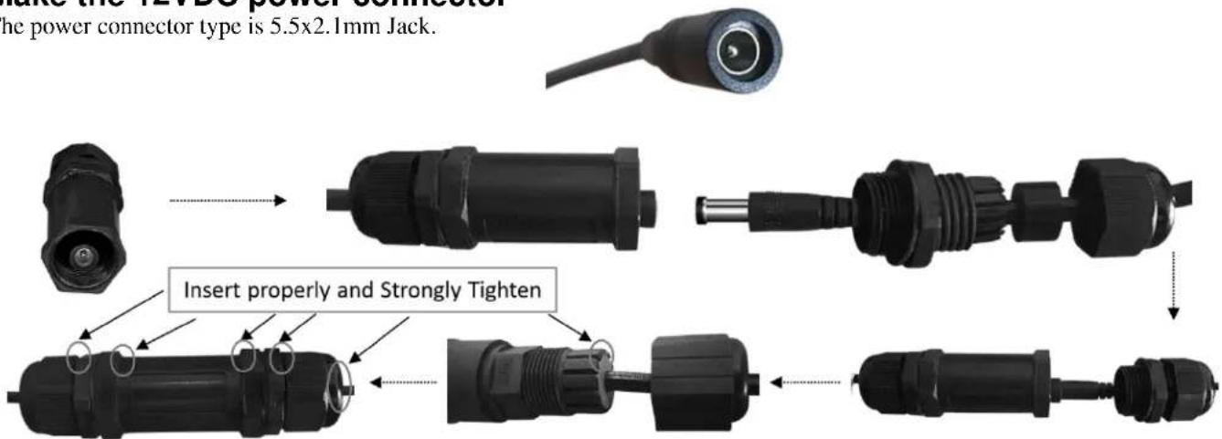
Make the 12VDC power connector
The power connector type is 5.5x2.1mm Jack.
text_image
Make the 12VDC power connector the power connector type is 5.5x2.1mm Jack. Insert properly and Strongly Tighten12VDC Power Connector + Waterproof Coupler Installation
Cable Requirements
- Network Cable: 10/100 Mbps Ethernet CAT 5/5E/6 UTP cables are applicable to the ANSI/EIA/TIA-568A/B and ISO/D. Eight wires in the network cable need to be inserted in parallel into the top of the cable connector. The cable connector needs to be crimped in position. When the cable connector is in position, ensure that the metal pieces of the cable connector are parallel to each other and the clamp of the cable connector is intact.
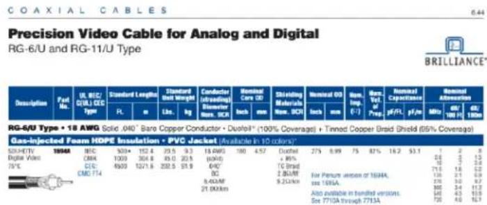
- SDI Cable: For broadcast use, Belden1694A/5CFB is a suitable cable to transmit broadcast-quality video:
1694A
text_image
Precision Video Cable for Analog and Digital RG-6/U and RG-11/U Type Description Past No. UL MEC/ C/UL CEC Type FL m Standard Unit Weight Lbs. kg Conductor (stranding) Biometer Nom. SCK Nominal Core OD inch mm Shrilling Materials Nom. SCK Nominal OD inch mm Nom. Exp. (F-T) Max Vol. of Prep pF/Ft pF/m Nominal Capacitance MHz dN 100 Ω dN 100m RG-5/U Type • 18 AWG Solid .040" Bare Copper Conductor • Durol® (100% Coverage) • Tinned Copper Braid Shield (65% Coverage) Gas-injected Foam HDPE Insulation • PVC Jacket [Available In 10 colors] 520x14V 1994 MFC 530* 152.4 25.5 9.3 18.6W0 180 4.57 Durol CMR 1300 364.8 85.0 22.9 (600) CIG: 4509 1221.6 232.5 51.9 0/4" CMO F14 CIG: BC 8.4Ω/MF 21.0Ω/km Ductel + 80% TG Band 2.8Ω/MF 9.2Ω/km For Figure version of 1994A, see 1995A. See available in tendered versions. See 77/0A through 77/0A. 725 3.0 9.7 800 3.4 11.7 700 4.0 16.7Conductor:
| AWG | Stranding | Material | Nominal Diameter |
| 18 | Solid | Bare Copper | 0.04 in. |
Shield Material
| Type | Layer | Material | Coverage |
| Tape | 1 | Aluminum / Polyester / Aluminum | 100% |
| Braid | 2 | Tinned Copper | 95% |
| Nom. Capacitance Conductor to shield | Nom. Inductance | Nom. Char. Impedance |
| 16.2 pF/ft | 0.106 μ H/ft | 75 Ohm |
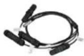
Install the Tail Cable
Install and detach the Tail Cable included with the product as following:
-
Hold the MS female connector head and pull back the ring of the connector.
-
Insert the MS female connector head into the MS male connector on the camera completely until you hear the lock sound when the connection is in place and release the ring.

natural_image
Three-panel image showing a white cylindrical device with internal components and connected cables, one labeled 'BOLiN' (no readable text or symbols beyond branding)Mounting the Camera
Check Camera Components and Installation Conditions Before mounting your camera, check the device model number and included contents against the packing list to ensure components are complete.
Important:
- Verify the bearing capacity of the surface where the camera will be mounted
- Verify that the mounted position meets the bearing requirements. Otherwise, you are advised to reinforce the mounted position to support the device weight. For more information, see the product datasheet.
- Verify lightning protection and grounding requirements
- Ground the terminal properly.

natural_image
Exterior view of a white BOLIN security camera mounted on a wall (no visible text or symbols)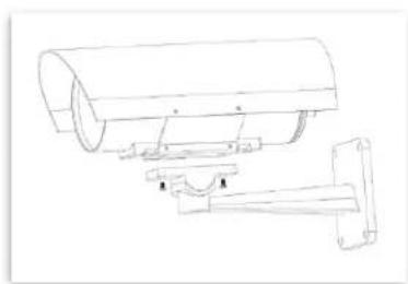
natural_image
Technical line drawing of a cylindrical mechanical component with attached bracket (no text or symbols)NOTE:
- When mounting the camera, please install the bracket adapter to the bracket first and then mount the camera to the bracket.
- Tighten all the screws to hold the camera securely.
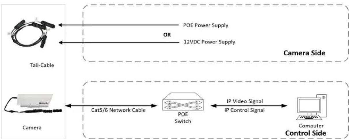
Power Connection
The camera provides two methods of power inputs, either POE (IEEE802.3at) or 12VDC.
flowchart
graph LR
    A["Tail-Cable"] -->|POE Power Supply| B["Camera"]
    A -->|OR| B
    B -->|IP Video Signal| C["Computer"]
    B -->|IP Control Signal| C
    C --> D["POE Switch"]
    D --> E["Cat5/6 Network Cable"]
    style A fill:#f9f,stroke:#333
    style B fill:#ccf,stroke:#333
    style C fill:#cfc,stroke:#333
    style D fill:#fcc,stroke:#333
    style E fill:#ffc,stroke:#333
Power up the camera
NOTE:
- Do not turn on the power nor connect the power/POE to the camera Tail Cable until the camera Tail Cable has been connected completely to the camera.
Use 12VDC or IEEE802.3at standard POE power adaptor or POE switch to power the camera. It takes about 2 minutes for the camera to be completely powered on.
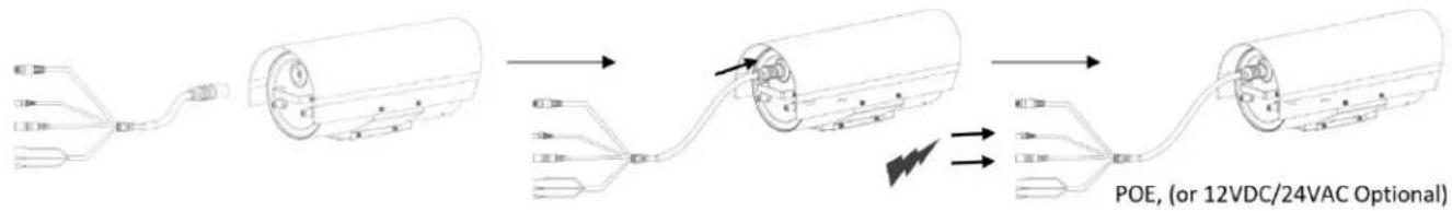
flowchart
graph LR
    A["Wireless Cable"] --> B["Switch"]
    B --> C["Coiled Cable"]
    C --> D["Terminal"]
    D --> E["POE (or 12VDC/24VAC Optional)"]
    style A fill:#f9f,stroke:#333
    style B fill:#ccf,stroke:#333
    style C fill:#cfc,stroke:#333
    style D fill:#fcc,stroke:#333
    style E fill:#cff,stroke:#333
NOTE:
• Use water proof/IP67 rated junction box/connection box to protect the RJ45 and other connections.
Control Connection
RS422 (VISCA) connection
- Only B class supports VISCA control., S class does not support VISCA control
- Follow the connection below to make the RS422 control connection for the keyboard controller.
- The camera default address is set to 1, default Baud Rate is set to 9600.
- Set the keyboard controller Baud Rate to 9600. The Baud Rate of the camera and the controller must be the same. The controller must be VISCA compatible.
- Use the keyboard controller to change the camera address using the camera's OSD menu.
- If you want the camera address to be automatically assigned by the VISCA controller, keep the camera address as the default address (set the camera address to 0 using the DIP switches).
- Reboot the camera by turning it Off/On after the camera address has been set up correctly.
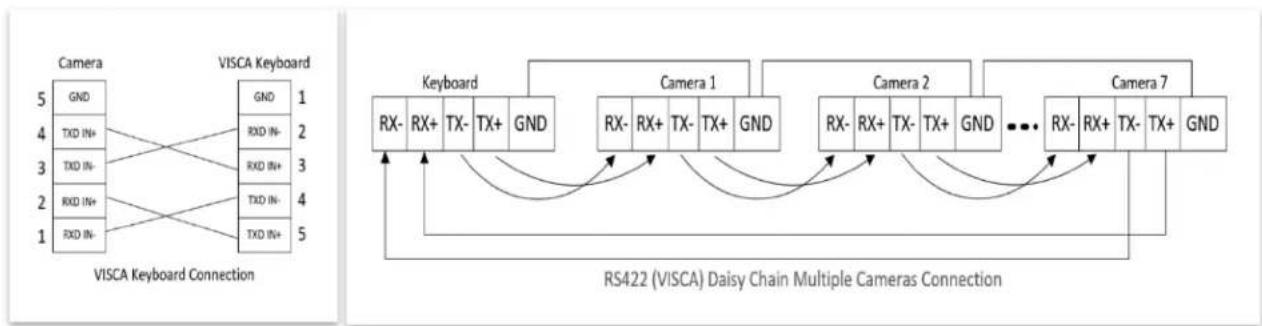
- Camera RS422 control supports Daisy Chain connection up to 7 cameras.
NOTE: The connection of SONY keyboard is different than other VISCA (Non-Sony) keyboard. The Chart below shows how to make RS422 (1 to 1) connection, as well as an RS422 Daisy Chain (multiple camera connection) using a SONY controller:
SONY Keyboard RS422 Connection
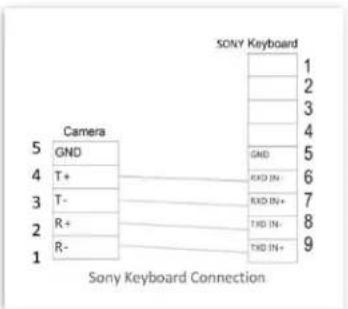
text_image
SONY Keyboard 1 2 3 4 5 Camera GND T+ R+ R- GND RXD IN- RXD IN+ THD IN- THD IN+ 9 Sony Keyboard Connection
flowchart
graph TD
    subgraph Camera 1
        RX- -->|RX-| RX+
        RX+ -->|TX-| TX-
        TX+ -->|GND| GND
    end
    subgraph Camera 2
        RX- -->|RX-| RX+
        RX+ -->|TX-| TX-
        TX+ -->|GND| GND
    end
    subgraph Camera 3
        RX- -->|RX-| RX+
        RX+ -->|TX-| TX-
        TX+ -->|GND| GND
    end
    subgraph Camera 4
        RX- -->|RX-| RX+
        RX+ -->|TX-| TX-
        TX+ -->|GND| GND
    end
    subgraph Camera 5
        RX- -->|RX-| RX+
        RX+ -->|TX-| TX-
        TX+ -->|GND| GND
    end
    subgraph Camera 6
        RX- -->|RX-| RX+
        RX+ -->|TX-| TX-
        TX+ -->|GND| GND
    end
    RS422["RS422 (VISCA) Daisy Chain Multiple Cameras Connection (Sony Keyboard)"]
- How to make RS422 connection (1 to 1) and RS422 Daisy Chain (multiple camera connection) using a Non-Sony controller:
VISCA (Non-Sony) Keyboard RS422 Connection
flowchart
graph TD
    subgraph VISCA Keyboard Connection
        A["Camera"] --> B["GND"]
        C["TXD IN+"] --> D["RXD IN-"]
        E["TXD IN-"] --> F["RXD IN+"]
        G["RXD IN+"] --> H["TXD IN-"]
        I["RXD IN-"] --> J["TXD IN+"]
        K["VISCA Keyboard"] --> L["GND"]
        M["TXD IN+"] --> N["RXD IN-"]
        O["TXD IN-"] --> P["RXD IN+"]
        Q["TXD IN-"] --> R["TXD IN-"]
        S["TXD IN+"]
    end
    subgraph RS422 (VISCA) Daisy Chain Multiple Cameras Connection
        T["Keyboard"] --> U["RX-"]
        V["RS422 (VISCA) Daisy Chain Multiple Cameras Connection"] --> W["RX+"]
        X["RS422 (VISCA) Daisy Chain Multiple Cameras Connection"] --> Y["TX-"]
        Z["RS422 (VISCA) Daisy Chain Multiple Cameras Connection"] --> AA["TX+"]
        AB["RS422 (VISCA) Daisy Chain Multiple Cameras Connection"] --> AC["GND"]
        AD["Camera 1"] --> AE["RX-"]
        AF["Camera 1"] --> AG["RX+"]
        AH["Camera 1"] --> AI["TX-"]
        AJ["Camera 1"] --> AK["TX+"]
        AL["Camera 1"] --> AM["GND"]
        AN["Camera 2"] --> AO["RX-"]
        AP["Camera 2"] --> AQ["RX+"]
        AR["Camera 2"] --> AS["TX-"]
        AT["Camera 2"] --> AU["TX+"]
        AV["Camera 2"] --> AW["GND"]
        AX["Camera 7"] --> AY["RX-"]
        AZ["RS422 (VISCA) Daisy Chain Multiple Cameras Connection"] --> BA["RX-"]
        BB["RS422 (VISCA) Daisy Chain Multiple Cameras Connection"] --> BC["RX+"]
        BD["RS422 (VISCA) Daisy Chain Multiple Cameras Connection"] --> BE["TX-"]
        BF["RS422 (VISCA) Daisy Chain Multiple Cameras Connection"] --> BG["TX+"]
        BH["RS422 (VISCA) Daisy Chain Multiple Cameras Connection"] --> BI["GND"]
    end
RS422 VISCA connection with RS422 serial port controller
- 1 to 1 RS422 connection. For how to make the connection on the controller, please refer to the controller user guide.

flowchart
graph TD
    A["Device with cable"] --> B["5 GND"]
    A --> C["4 RX-"]
    A --> D["3 RX+"]
    A --> E["2 TX-"]
    A --> F["1 TX+"]
    B --> G["GND"]
    C --> H["RX+"]
    D --> I["RX-"]
    E --> J["TX+"]
    F --> K["TX-"]
    G --> L["RS422 Serial port connection on controller side."]
    H --> L
    I --> L
    J --> L
    K --> L
    L --> M["RS422 Connection Icon"]
    N["NOTE: How to make RS422 connection, please refer to controller user guide."] --> L
RS422 Connection – Controller with RS422 serial connector
- RS422 Daisy Chain multiple camera connection. For how to make the connection on the controller, please refer to the controller user guide.

flowchart
graph TD
    A["Control Cables"] --> B["RS422 Serial port connection on controller side"]
    B --> C["RS422 (VISCA) Daisy Chain Multiple Cameras Connection"]
    C --> D["RS422 Serial port connection on controller side"]
    D --> E["RS422 Serial port connection on controller side"]
    E --> F["RS422 Serial port connection on controller side"]
    F --> G["RS422 Serial port connection on controller side"]
    G --> H["RS422 Serial port connection on controller side"]
    H --> I["RS422 Serial port connection on controller side"]
    I --> J["RS422 Serial port connection on controller side"]
    J --> K["RS422 Serial port connection on controller side"]
    K --> L["RS422 Serial port connection on controller side"]
    L --> M["RS422 Serial port connection on controller side"]
    M --> N["RS422 Serial port connection on controller side"]
    N --> O["RS422 Serial port connection on controller side"]
    O --> P["RS422 Serial port connection on controller side"]
    P --> Q["RS422 Serial port connection on controller side"]
    Q --> R["RS422 Serial port connection on controller side"]
    R --> S["RS422 Serial port connection on controller side"]
    S --> T["RS422 Serial port connection on controller side"]
    T --> U["RS422 Serial port connection on controller side"]
    U --> V["RS422 Serial port connection on controller side"]
    V --> W["RS422 Serial port connection on controller side"]
    W --> X["RS422 Serial port connection on controller side"]
    X --> Y["RS422 Serial port connection on controller side"]
    Y --> Z["RS422 Serial port connection on controller side"]
    Z --> AA["RS422 Serial port connection on controller side"]
    AA --> AB["RS422 Serial port connection on controller side"]
    AB --> AC["RS422 Serial port connection on controller side"]
    AC --> AD["RS422 Serial port connection on controller side"]
    AD --> AE["RS422 Serial port connection on controller side"]
    AE --> AF["RS422 Serial port connection on controller side"]
    AF --> AG["RS422 Serial port connection on controller side"]
    AG --> AH["RS422 Serial port connection on controller side"]
    AH --> AI["RS422 Serial port connection on controller side"]
    AI --> AJ["RS422 Serial port connection on controller side"]
    AJ --> AK["RS422 Serial port connection on controller side"]
    AK --> AL["RS422 Serial port connection on controller side"]
    AL --> AM["RS422 Serial port connection on controller side"]
    AM --> AN["RS422 Serial port connection on controller side"]
    AN --> AO["RS422 Serial port connection on controller side"]
    AO --> AP["RS422 Serial port connection on controller side"]
    AP --> AQ["RS422 Serial port connection on controller side"]
    AQ --> AR["RS422 Serial port connection on controller side"]
    AR --> AS["RS422 Serial port connection on controller side"]
    AS --> AT["RS422 Serial port connection on controller side"]
    AT --> AU["RS422 Serial port connection on controller side"]
    AU --> AV["RS422 Serial port connection on controller side"]
    AV --> AW["RS422 Serial port connection on controller side"]
    AW --> AX["RS422 Serial port connection on controller side"]
    AX --> AY["RS422 Serial port connection on controller side"]
    AY --> AZ["RS422 Serial port connection on controller side"]
    AZ --> BA["RS422 Serial port connection on controller side"]
    BA --> BB["RS422 Serial port connection on controller side"]
    BB --> BC["RS422 Serial port connection on controller side"]
    BC --> BD["RS422 Serial port connection on controller side"]
    BD --> BE["RS422 Serial port connection on controller side"]
    BE --> BF["RS422 Serial port connection on controller side"]
    BF --> BG["RS422 Serial port connection on controller side"]
    BG --> BH["RS422 Serial port connection on controller side"]
    BH --> BI["RS422 Serial port connection on controller side"]
    BI --> BJ["RS422 Serial port connection on controller side"]
    BJ --> BK["RS422 Serial port connection on controller side"]
    BK --> BL["RS422 Serial port connection on controller side"]
    BL --> BM["RS422 Serial port connection on controller side"]
    BM --> BN["RS422 Serial port connection on controller side"]
    BN --> BO["RS422 Serial port connection on controller side"]
    BO --> BP["RS422 Serial port connection on controller side"]
    BP --> BQ["RS422 Serial port connection on controller side"]
    BQ --> BR["RS422 Serial port connection on controller side"]
    BR --> BS["RS422 Serial port connection on controller side"]
    BS --> BT["RS422 Serial port connection on controller side"]
    BT --> BU["RS422 Serial port connection on controller side"]
    BU --> BV["RS422 Serial port connection on controller side"]
    BV --> BW["RS422 Serial port connection on controller side"]
    BW --> BX["GND"]
    BX --> BY["GND"]
    BY --> BZ["GND"]
    BZ --> CA["GND"]
    CA --> CB["GND"]
    CB --> CC["GND"]
    CC --> CD["GND"]
    CD --> CE["GND"]
RS422 Daisy Chain Connection – Controller with RS422 serial connector
RS422 VISCA connection with Bolin KBD-1010 controller
- How to make 1 to 1 RS422 connection with Bolin KBD-1010 controller as below or refer to Bolin KBD-1010 user guide. a. 1 to 1 RS422 connection, use Junction Box connection.
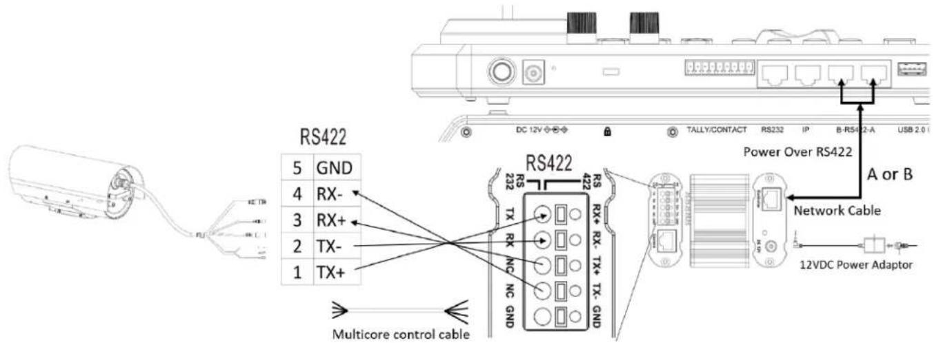
text_image
RS422 5 GND 4 RX- 3 RX+ 2 TX- 1 TX+ RS422 RS TX RX NC NC GND RS422 422 RS TX TX+ Network Cable Power Over RS422 A or B 12VDC Power Adaptor Multicore control cableRS422 Connection – Bolin Controller
b. 1 to 1 RS422 connection using RJ45 to Phoenix connector adaptor (Not Included, sold separately)
flowchart
graph LR
    A["Device"] --> B["Wireless Cable"]
    B --> C["RS422 Sensor"]
    C --> D["12VDC Power Adaptor"]
    D --> E["RS422 Interface"]
    E --> F["Keyboard RJ45 to RS422/232 Adaptor (Not Included)"]
    C --> G["GND"]
    C --> H["RX-"]
    C --> I["RX+"]
    C --> J["TX-"]
    C --> K["TX+"]
    C --> L["GND"]
    style A fill:#f9f,stroke:#333
    style E fill:#ccf,stroke:#333
    style F fill:#cfc,stroke:#333
    style G fill:#fcc,stroke:#333
    style H fill:#fcc,stroke:#333
    style I fill:#fcc,stroke:#333
    style J fill:#fcc,stroke:#333
    style K fill:#fcc,stroke:#333
    style L fill:#fcc,stroke:#333
RS422 connection with BOLIN KBD1010 Controller
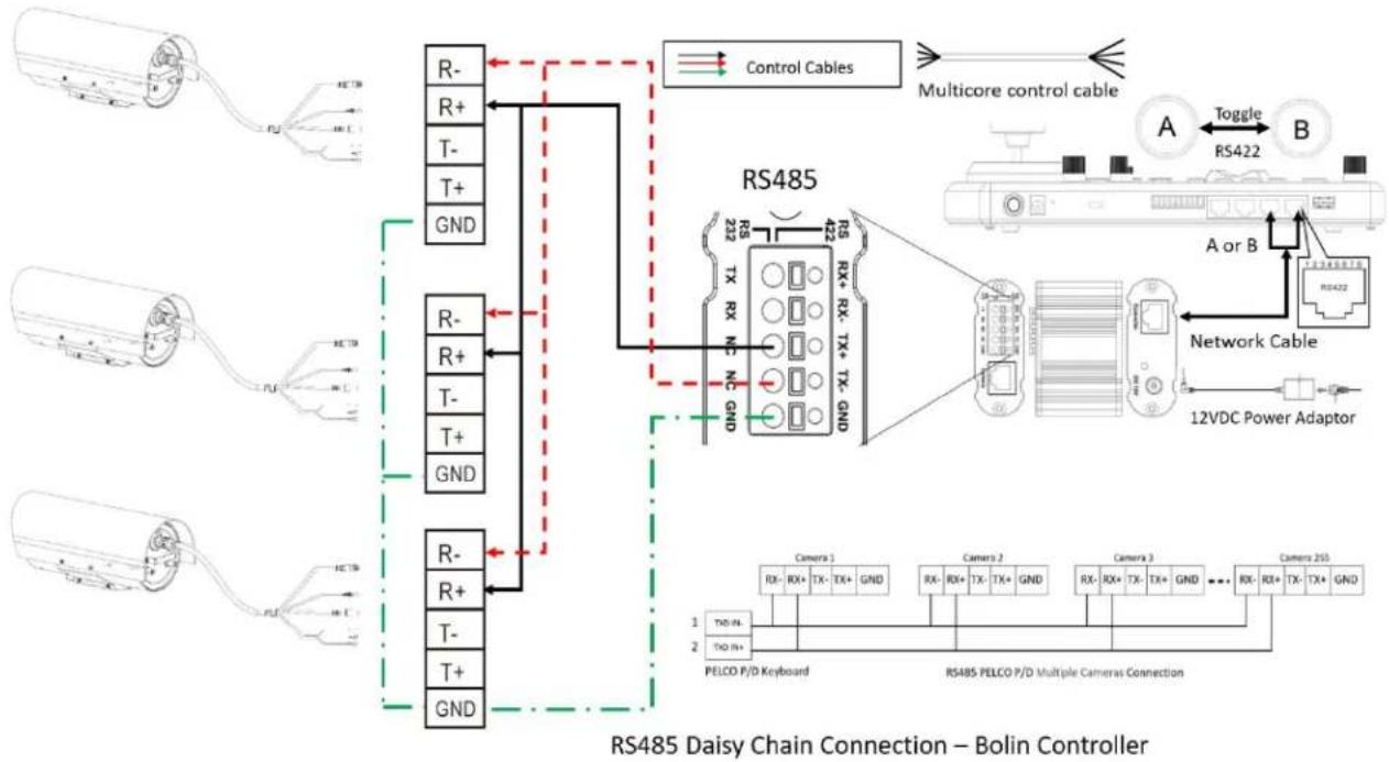
- How to make RS422 Daisy Chain multiple camera connection with Bolin KBD-1010 controller as below or refer to Bolin KBD-1010 user guide
a. RS422 Daisy Chain connection, use Junction Box connection
flowchart
graph TD
    subgraph_Control_Cables["Control Cables"]
        R- --> R+ --> T- --> T+ --> GND
        R+ --> R- --> T- --> T+ --> GND
    end
    subgraph_RS422["RS422"]
        R- --> R+ --> T- --> T+ --> GND
    end
    R- --> RS422
    RS422 --> Rx_1["RX- RX+ TX- TX+ GND"]
    RS422 --> Rx_2["RX- RX+ TX- TX+ GND"]
    RS422 --> Rx_3["RX- RX+ TX- TX+ GND"]
    RS422 --> Rx_4["RX- RX+ TX- TX+ GND"]
    RS422 --> Rx_5["RX- RX+ TX- TX+ GND"]
    RS422 --> Rx_6["RX- RX+ TX- TX+ GND"]
    RS422 --> Rx_7["RX- RX+ TX- TX+ GND"]
    RS422 --> Rx_8["RX- RX+ TX- TX+ GND"]
    RS422 --> Rx_9["RX- RX+ TX- TX+ GND"]
    RS422 --> Rx_10["RX- RX+ TX- TX+ GND"]
    RS422 --> Rx_11["RX- RX+ TX- TX+ GND"]
    RS422 --> Rx_12["RX- RX+ TX- TX+ GND"]
    RS422 --> Rx_13["RX- RX+ TX- TX+ GND"]
    RS422 --> Rx_14["RX- RX+ TX- TX+ GND"]
    RS422 --> Rx_15["RX- RX+ TX- TX+ GND"]
    RS422 --> Rx_16["RX- RX+ TX- TX+ GND"]
    RS422 --> Rx_17["RX- RX+ TX- TX+ GND"]
    RS422 --> Rx_18["RX- RX+ TX- TX+ GND"]
    RS422 --> Rx_19["RX- RX+ TX- TX+ GND"]
    RS422 --> Rx_20["RX- RX+ TX- TX+ GND"]
    RS422 --> Rx_21["RX- RX+ TX- TX+ GND"]
    RS422 --> Rx_22["RX- RX+ TX- TX+ GND"]
    RS422 --> Rx_23["RX- RX+ TX- TX+ GND"]
    RS422 --> Rx_24["RX- RX+ TX- TX+ GND"]
    RS422 --> Rx_25["RX- RX+ TX- TX+ GND"]
    RS422 --> Rx_26["RX- RX+ TX- TX+ GND"]
    RS422 --> Rx_27["RX- RX+ TX- TX+ GND"]
    RS422 --> Rx_28["RX- RX+ TX- TX+ GND"]
    RS422 --> Rx_29["RX- RX+ TX- TX+ GND"]
    RS422 --> Rx_30["RX- RX+ TX- TX+ GND"]
    RS422 --> Rx_31["RX- RX+ TX- TX+ GND"]
    RS422 --> Rx_32["RX- RX+ TX- TX+ GND"]
    RS422 --> Rx_33["RX- RX+ TX- TX+ GND"]
    RS422 --> Rx_34["RX- RX+ TX- TX+ GND"]
    RS422 --> Rx_35["RX- RX+ TX- TX+ GND"]
    RS422 --> Rx_36["RX- RX+ TX- TX+ GND"]
    RS422 --> Rx_37["RX- RX+ TX- TX+ GND"]
    RS422 --> Rx_38["RX- RX+ TX- TX+ GND"]
    RS422 --> Rx_39["RX- RX+ TX- TX+ GND"]
    RS422 --> Rx_40["RX- RX+ TX- TX+ GND"]
    RS422 --> Rx_41["RX- RX+ TX- TX+ GND"]
    RS422 --> Rx_42["RX- RX+ TX- TX+ GND"]
    RS422 --> Rx_43["RX- RX+ TX- TX+ GND"]
    RS422 --> Rx_44["RX- RX+ TX- TX+ GND"]
    RS422 --> Rx_45["RX- RX+ TX- TX+ GND"]
    RS422 --> Rx_46["RX- RX+ TX- TX+ GND"]
    RS422 --> Rx_47["RX- RX+ TX- TX+ GND"]
    RS422 --> Rx_48["RX- RX+ TX- TX+ GND"]
    RS422 --> Rx_49["RX- RX+ TX- TX+ GND"]
    RS422 --> Rx_50["RX- RX+ TX- TX+ GND"]
    RS422 --> Rx_51["RX- RX+ TX- TX+ GND"]
    RS422 --> Rx_52["RX- RX+ TX- TX+ GND"]
    RS422 --> Rx_53["RX- RX+ TX- TX+ GND"]
    RS422 --> Rx_54["RX- RX+ TX- TX+ GND"]
    RS422 --> Rx_55["RX- RX+ TX- TX+ GND"]
    RS422 --> Rx_56["RX- RX+ TX- TX+ GND"]
    RS422 --> Rx_57["RX- RX+ TX- TX+ GND"]
    RS422 --> Rx_58["RX- RX+ TX- TX+ GND"]
    RS422 --> Rx_59["RX- RX+ TX- TX+ GND"]
    RS422 --> Rx_60["RX- RX+ TX- TX+ GND"]
    RS422 --> Rx_61["RX- RX+ TX- TX+ GND"]
    RS422 --> Rx_62["RX- RX+ TX- TX+ GND"]
    RS422 --> Rx_63["RX- RX+ TX- TX+ GND"]
    RS422 --> Rx_64["RX- RX+ TX- TX+ GND"]
    RS422 --> Rx_65["RX- RX+ TX- TX+ GND"]
    RS422 --> Rx_66["RX- RX+ TX- TX+ GND"]
    RS422 --> Rx_67["RX- RX+ TX- TX+ GND"]
    RS422 --> Rx_68["RX- RX+ TX- TX+ GND"]
    RS422 --> Rx_69["RX- RX+ TX- TX+ GND"]
    RS422 --> Rx_70["RX- RX+ TX- TX+ GND"]
    RS422 --> Rx_71["RX- RX+ TX- TX+ GND"]
    RS422 --> Rx_72["RX- RX+ TX- TX+ GND"]
    RS422 --> Rx_73["RX- RX+ TX- TX+ GND"]
    RS422 --> Rx_74["RX- RX+ TX- TX+ GND"]
    RS422 --> Rx_75["RX- RX+ TX- TX+ GND"]
    RS422 --> Rx_76["RX- RX+ TX- TX+ GND"]
    RS422 --> Rx_77["RX- RX+ TX- TX+ GND"]
    RS422 --> Rx_78["RX- RX+ TX- TX+ GND"]
    RS422 --> Rx_79["RX- RX+ TX- TX+ GND"]
    RS422 --> Rx_80["RX- RX+ TX- TX+ GND"]
RS422 Daisy Chain Connection – Bolin Controller
b. RS422 Daisy Chain connection using RJ45 to Phoenix connector adaptor (Not Included, sold separately)

flowchart
graph TD
    A["Control Cables"] --> B["RS422"]
    B --> C["RS422 (ViSCA) Daisy Chain Multiple Cameras Connection"]
    C --> D["RS422 / RS422/232 Adaptor (Not Included)"]
    D --> E["Keyboard"]
    E --> F["RS422"]
    style A fill:#f9f,stroke:#333
    style B fill:#ccf,stroke:#333
    style C fill:#cfc,stroke:#333
    style D fill:#fcc,stroke:#333
    style E fill:#ffc,stroke:#333
    style F fill:#fcc,stroke:#333
RS422 Daisy Chain Connection – Bolin Controller
PELCO P/D Keyboard RS485 Connection
- Follow the connection below to make the RS485 control connection for the keyboard controller.
- The camera default address is set to 1, default Baud Rate is set to 9600.
- Set the keyboard controller Baud Rate to 9600. The Baud Rate of the camera and the controller must be the same.
- Use the keyboard controller to change the camera address.
- The controller must be PELCO D/P compatible. Use preset 95# on the keyboard to bring up/exit camera OSD menu. To operate keyboard, please refer to the user manual of the keyboard you are using.
- Reboot the camera by turning it Off/On after the camera address has been set up correctly.
- Camera RS485 multi camera control supports connection up to 255 cameras.

flowchart
graph LR
    A["Camera"] -->|6| B["RS485+"]
    A -->|7| C["RS485-"]
    D["PELCO P/D Keyboard"] -->|1| E["TXD IN-"]
    D -->|2| F["TXD IN+"]
    B <--> C

flowchart
graph LR
    subgraph "PELCO P/D Keyboard"
        A["1 TXD IN-"] --> B["2 TXD IN+"]
    end
    subgraph "RS485 PELCO P/D Multiple Cameras Connection"
        C["1 RX-"] --> D["2 RX+"]
        E["2 RX-"] --> F["3 RX+"]
        G["3 RX-"] --> H["4 RX+"]
        I["4 RX-"] --> J["5 RX+"]
        K["5 RX-"] --> L["6 RX+"]
        M["6 RX-"] --> N["7 RX+"]
        O["7 RX-"] --> P["8 RX+"]
        Q["8 RX-"] --> R["9 RX+"]
        S["9 RX-"] --> T["10 RX+"]
        U["10 RX-"] --> V["11 RX+"]
        W["11 RX-"] --> X["12 RX+"]
        Y["12 RX-"] --> Z["13 RX+"]
        AA["13 RX-"] --> AB["14 RX+"]
        AC["14 RX-"] --> AD["15 RX+"]
        AE["15 RX-"] --> AF["16 RX+"]
        AG["16 RX-"] --> AH["17 RX+"]
        AI["17 RX-"] --> AJ["18 RX+"]
        AK["18 RX-"] --> AL["19 RX+"]
        AM["19 RX-"] --> AN["20 RX+"]
        AO["20 RX-"] --> AP["21 RX+"]
        AQ["21 RX-"] --> AR["22 RX+"]
        AS["22 RX-"] --> AT["23 RX+"]
        AU["23 RX-"] --> AV["24 RX+"]
        AW["24 RX-"] --> AX["25 RX+"]
    end
    style A fill:#f9f,stroke:#333
    style B fill:#ccf,stroke:#333
    style C fill:#cfc,stroke:#333
    style D fill:#fcc,stroke:#333
    style E fill:#cff,stroke:#333
    style F fill:#ffc,stroke:#333
    style G fill:#fcc,stroke:#333
    style H fill:#fcc,stroke:#333
    style I fill:#fcc,stroke:#333
    style J fill:#fcc,stroke:#333
    style K fill:#fcc,stroke:#333
    style L fill:#fcc,stroke:#333
    style M fill:#fcc,stroke:#333
    style N fill:#fcc,stroke:#333
    style O fill:#fcc,stroke:#333
    style P fill:#fcc,stroke:#333
    style Q fill:#fcc,stroke:#333
    style R fill:#fcc,stroke:#333
    style S fill:#fcc,stroke:#333
    style T fill:#fcc,stroke:#333
    style U fill:#fcc,stroke:#333
    style V fill:#fcc,stroke:#333
    style W fill:#fcc,stroke:#333
    style X fill:#fcc,stroke:#333
    style Y fill:#fcc,stroke:#333
RS485 PELCO connection with RS485 serial port controller
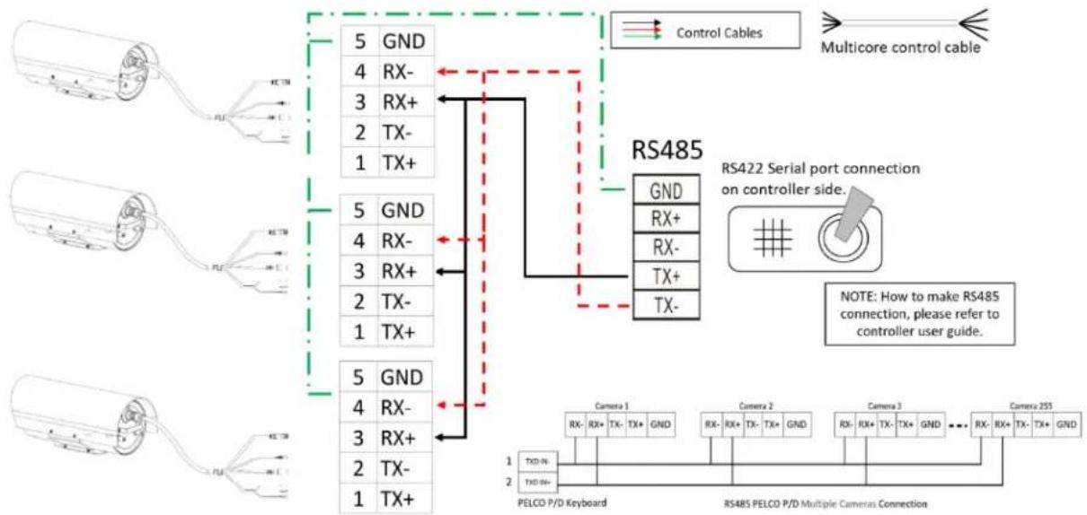
- 1 to 1 RS485 connection. For how to make the connection on the controller, please refer to the controller user guide.

flowchart
graph TD
    A["Motor Cable"] --> B["5 GND"]
    A --> C["4 RX-"]
    A --> D["3 RX+"]
    A --> E["2 TX-"]
    A --> F["1 TX+"]
    B --> G["GND"]
    C --> H["RX+"]
    D --> I["RX-"]
    E --> J["TX+"]
    F --> K["TX-"]
    G --> L["RS485 Serial Port Connection on Controller Side"]
    H --> L
    I --> L
    J --> L
    K --> L
    L --> M["RS422 Serial Port Connection on Controller Side"]
    N["Multicore control cable"] --> O["↔"]
    P["NOTE: How to make RS485 connection, please refer to controller user guide."]
RS485 Connection – Controller with RS485 serial connector
- RS485 Daisy Chain multiple camera connection. To make the connection on the controller, please refer to controller user guide.
flowchart
graph TD
    A["Control Cables"] --> B["RS485 Serial Port Connection"]
    B --> C["RS422 Serial Port Connection on Controller Side"]
    C --> D["RS485 PELCD P/D Multiple Cameras Connection"]
    D --> E["PELOD P/D Keyboard"]
    D --> F["RS485 PELCD P/D Multiple Cameras Connection"]
    style A fill:#f9f,stroke:#333
    style B fill:#ccf,stroke:#333
    style C fill:#cfc,stroke:#333
    style D fill:#fcc,stroke:#333
RS485 Daisy Chain Connection – Controller with RS485 serial connector
RS485 PELCO connection with Bolin KBD-1010 controller
- How to make 1 to 1 RS485 connection with Bolin KBD-1010 controller as below or refer to Bolin KBD-1010 user guide. a. 1 to 1 RS485 connection, use Junction Box connection.
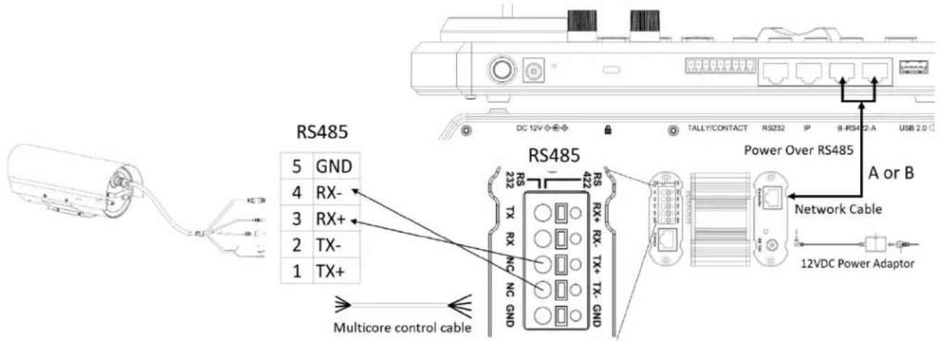
text_image
RS485 5 GND 4 RX- 3 RX+ 2 TX- 1 TX+ RS485 232 TX RX NC NC GND RS TX RX+ RX- TX+ TX-GND Power Over RS485 A or B Network Cable 12VDC Power Adaptor Multicore control cableRS485 Connection – Bolin Controller
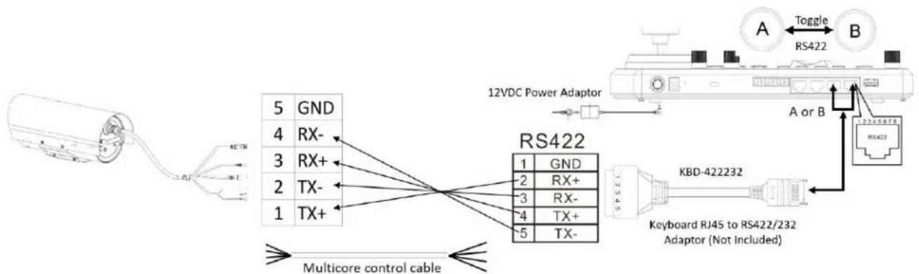
b. 1 to 1 RS485 connection using RJ45 to Phoenix connector adaptor (Not Included, sold separately)

text_image
5 GND 4 RX- 3 RX+ 2 TX- 1 TX+ Multicore control cable 1 GND 2 RX+ 3 RX- 4 TX+ 5 TX- 12VDC Power Adaptor A Toggle RS485 B A or B KBD-422232 Keyboard RJ45 to RS422/232 Adaptor (Not Included)RS485 connection with BOLIN KBD1010 Controller
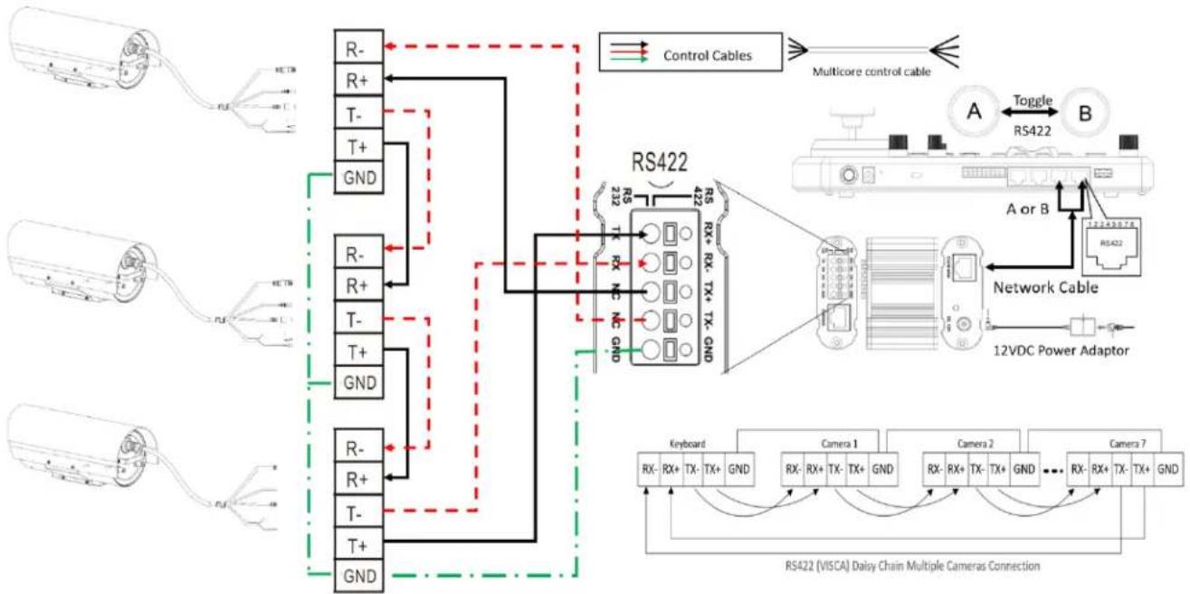
- How to make RS485 Daisy Chain multiple camera connection with Bolin KBD-1010 controller as below or refer to Bolin KBD-1010 user guide
a. RS485 Daisy Chain connection, use Junction Box connection
flowchart
graph TD
    A["RS485 Daisy Chain Connection – Bolin Controller"] --> B["RS485"]
    B --> C["RS485 PELCO Multiple Cameras Connection"]
    C --> D["12VDC Power Adaptor"]
    D --> E["Network Cable"]
    E --> F["RS422"]
    F --> G["Toggle"]
    G --> H["A or B"]
    H --> I["RS422"]
    I --> J["12VDC Power Adaptor"]
    J --> K["RS485"]
    K --> L["Control Cables"]
    L --> M["RS485"]
    M --> N["12VDC Power Adaptor"]
    N --> O["RS485 PELCO Multiple Cameras Connection"]
    O --> P["12VDC Power Adaptor"]
    P --> Q["RS485 PELCO Multiple Cameras Connection"]
    Q --> R["12VDC Power Adaptor"]
    R --> S["RS485 PELCO Multiple Cameras Connection"]
    S --> T["12VDC Power Adaptor"]
    T --> U["RS485 PELCO Multiple Cameras Connection"]
    U --> V["12VDC Power Adaptor"]
    V --> W["RS485 PELCO Multiple Cameras Connection"]
    W --> X["12VDC Power Adaptor"]
    X --> Y["RS485 PELCO Multiple Cameras Connection"]
    Y --> Z["12VDC Power Adaptor"]
    Z --> AA["RS485 PELCO Multiple Cameras Connection"]
    AA --> AB["12VDC Power Adaptor"]
    AB --> AC["RS485 PELCO Multiple Cameras Connection"]
    AC --> AD["12VDC Power Adaptor"]
    AD --> AE["RS485 PELCO Multiple Cameras Connection"]
    AE --> AF["12VDC Power Adaptor"]
    AF --> AG["RS485 PELCO Multiple Cameras Connection"]
    AG --> AH["12VDC Power Adaptor"]
    AH --> AI["RS485 PELCO Multiple Cameras Connection"]
    AI --> AJ["12VDC Power Adaptor"]
    AJ --> AK["RS485 PELCO Multiple Cameras Connection"]
    AK --> AL["12VDC Power Adaptor"]
    AL --> AM["RS485 PELCO Multiple Cameras Connection"]
    AM --> AN["12VDC Power Adaptor"]
    AN --> AO["RS485 PELCO Multiple Cameras Connection"]
    AO --> AP["12VDC Power Adaptor"]
    AP --> AQ["RS485 PELCO Multiple Cameras Connection"]
    AQ --> AR["12VDC Power Adaptor"]
    AR --> AS["RS485 PELCO Multiple Cameras Connection"]
    AS --> AT["12VDC Power Adaptor"]
    AT --> AU["RS485 PELCO Multiple Cameras Connection"]
    AU --> AV["12VDC Power Adaptor"]
    AV --> AW["RS485 PELCO Multiple Cameras Connection"]
    AW --> AX["12VDC Power Adaptor"]
    AX --> AY["RS485 PELCO Multiple Cameras Connection"]
    AY --> AZ["12VDC Power Adaptor"]
    AZ --> BA["RS485 PELCO Multiple Cameras Connection"]
    BA --> BB["12VDC Power Adaptor"]
    BB --> BC["RS485 PELCO Multiple Cameras Connection"]
    BC --> BD["12VDC Power Adaptor"]
    BD --> BE["RS485 PELCO Multiple Cameras Connection"]
    BE --> BF["12VDC Power Adaptor"]
    BF --> BG["RS485 PELCO Multiple Cameras Connection"]
    BG --> BH["12VDC Power Adaptor"]
b. RS485 Daisy Chain connection using RJ45 to Phoenix connector adaptor (Not Included, sold separately)

flowchart
graph TD
    A["Control Cables"] --> B["RS485"]
    B --> C["RS485 Daisy Chain Connection – Bolin Controller"]
    C --> D["PELCO P/D Keyboard"]
    C --> E["RS485 PELCO P/D Multiple Cameras Connection"]
    D --> F["RS485"]
    E --> G["RS485"]
    style A fill:#f9f,stroke:#333
    style B fill:#ccf,stroke:#333
    style C fill:#cfc,stroke:#333
    style D fill:#fcc,stroke:#333
    style E fill:#cff,stroke:#333
Note
For VISCA / PELCO control, this unit supports daisy chain connection for using multiple cameras.
For control details, refer to Operating Instructions of control keyboard/station software.
- You need to match the communication speed (Baud Rate) between the camera and the joystick controller.
Operating Multiple Cameras Using RS422/485
• Using RS-422 (VISCA), you can connect to 7 cameras.
• Using RS-485 (PELCO), you can connect to 255 cameras.
- Using RS-485 (PELCO), all camera addresses must be set up before the connection. You can set the camera address by operating OSD menu. In this case, you can use multiple control keyboards.
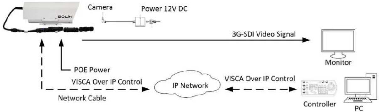
VISCA over IP Control
With VISCA over IP function, you can control the camera using VISCA protocol on a controller equipped with IP communication capabilities via LAN.
flowchart
graph LR
    A["BOLIN"] -->|POE Power| B["IP Network"]
    B -->|VISCA Over IP Control| C["Controller"]
    C -->|VISCA Over IP Control| D["PC"]
    D --> E["Monitor"]
    A --> F["Camera"]
    F --> G["Power 12V DC"]
    G --> H["3G-SDI Video Signal"]
    H --> I["Network Cable"]
    I --> B
The communication specifications of VISCA over IP are follows:
- Interface
RJ-45 10/100M
- Interface protocol
IPv4
- Transport protocol
UDP
-
IP address (Default:192.168.0.13)
-
Port: 52381
VISCA over IP Network Configuration Re-assign the camera
The default information of the IP camera is following:
• Static IP: 192.168.0.13
- Subnet mask: 255.255.255.0
• Gateway: 192.168.0.1
• VISCA over IP control port: 52381.
The camera IP address needs to be assigned to the IP address that works with your local network.
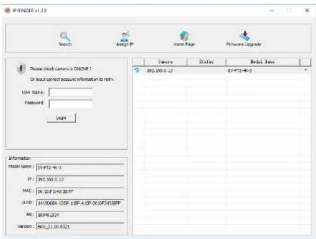
text_image
IP-FINDER v1.29 Search Assign IP Home Page Firmware Upgrade Please check camera is ONLINE? Or input correct account information to retn. User Name: Password: Login Camera Status Model Bars EPL-305.0.13 EY-PTZ-4K-3 Model Name: EY-PTZ-4K-3 IP: 192.358.0.13 MAC: 00.00F 204300.07 UUID: 141066A-10DF 18F-4 0F-00 0F3438PF SN: 10940.1224 Version: 801_01.00.0021Controlling via VISCA over IP
• Physically connect the network port on the camera to the network switch
- Set the IP address and other network information appropriately to communicate on your network
- Connect the VISCA over IP-compatible controller to the network
- Configure the controller to access the camera's IP address and VISCA over IP port
• The IP port within on your control must be set to 52381 to communicate with the camera.
- Select VISCA protocol on your IP control device.
Recommended way to re-assign the IP address:
- Create a local network within which the camera and your PC/Laptop are connected.
- Install and run the IP-FINDER tool (You can contact Bolin Technical support team for tool requirements)
- The IP-FINDER can find the camera IP address, which is the default :192.168.0.13
- Click the search button, select the camera you want to Assign IP address, edit the IP address to the one that matches your local network credential.
- Once the IP address has been changed successfully, you can access the IP camera via your local network.
Note
How to re-assign the IP address to the camera, please refer to user manual Part Two-IP Camera user guide.
Setup Camera ID, Baud Rate and Control Protocol
- For you to control a camera, the camera ID, baud rate and control protocol must be set up in advance. The baud rate and the camera ID setting within the Camera must match the baud rate and camera ID setting on the system/control keyboard.
- The camera can auto detect the protocol being used based on the cables that are connected to its tail cable contacts (RS422/ VISCA and RS485/PELCO-D). Please be sure to set up the camera address and baud rate within the camera.
- Connect the camera to a monitor before powering on. Once powered, there is an initial setting page that will be displayed on the screen for 5 seconds. On the page, it shows the factory default setting of the camera ID, baud rate and other information. Some users find it helpful to take a picture of this default setting information, so it can be referenced when setting up a keyboard controller.
-
Set the keyboard or control system to match the camera protocol, camera ID, and baud rate setting with the camera.
-
Camera supports VISCA and PELCO-D protocols. When connecting a controller to the camera's contacts, the protocol being used is detected automatically by the camera.
• Factory Default Setting: For both SDI and IP video, Baud Rate: 9600, Camera ID: 001, PELCO Protocol.
• RS485 PELCO-D can control up to 255 cameras. Camera ID from 001 to 255 must be set.
• RS422 VISCA protocol can control up to 7 cameras. Camera ID from 1 to 7 must be set.
• Supports baud rate of 2400bps, 4800bps, 9600bps and 38400bps. - How to set up the address and baud rate of the camera for SDI.
- If using a BOLIN KBD-1010 keyboard controller to control the camera, please follow these steps to set up RS485 control, Enter the Setup menu, and go into the Camera Setting menu, select the camera address/ID you want to set up for, set the baud rate to match the same as the one has been set on camera side, select protocol PELCO-D for RS485 control.
- If using a BOLIN KBD-1010 to control this camera using VISCA control, select RS232/RS422 control method, set the baud rate to match the same as the one has been set on camera side.
- NOTE: If you are using a keyboard other than the BOLIN KBD-1010, please refer to the user manual for your
keyboard controller for further instructions
- On the camera's IP control side, go into the camera IP web interface setting page by using browser to login camera IP address (Default set to 192.168.0.13), PTZ - Basic Settings page, to set the Baud Rate, camera ID, Protocol to the same as the ones that have been set on the camera's SDI side. (For further details, please refer to Part Two: Network Camera User Manual)
- SDI and IP video setting must be matching with each other, if you change any one of the settings on any sides of the SDI or IP.

text_image
Basic Settings Basic Settings Address Code 1 (1~255) Baud rate 9600 Save
NOTE!
- Regarding the camera ID and Baud Rate setting, for the first communication setting, you must match the control system (or keyboard) camera ID and Baud Rate setting to the cameras.
- After communicating successfully in between the camera and the control, you can modify the ID and baud rate of the camera using the keyboard.
- By default, the camera Baud Rate
Adjusting and Setting with Menus
About On-Screen Menus
You can change various settings, such as shooting conditions and system setup of the camera, while observing menus displayed on a connected computer screen.
This section explains how to read the on-screen menus before starting menu operations.
The menu parameters may vary according to the different product model numbers.
For a complete configurations menu, see "Menu Configuration".

NOTE!
You cannot perform pan/tilt/zoom operations while the menu is displayed.
Using the OSD Menu using a Keyboard Controller
Call preset 95 using the keyboard controller to call/display the On-Screen Menu, the main menu will display on the screen.
How to run presets of cameras, please refer to the manual of the keyboard/control system that you are using.
How to adjust settings using a joystick on a keyboard controller
- Push the joystick of the keyboard up or down: To select the menu item
- Push the joystick of the keyboard to the right: To select/ confirm
- Push the joystick of the keyboard to the right: To confirm the value that you want to set to.

When the camera runs with PELCO-D protocol, Call preset 95 to enter the On-Screen Menu by using control keyboard, the main menu will display on the screen.
When the camera runs with VISCA protocol, press the Menu button on the VISCA-compatible control keyboard to enter the OSD Menu.
EXPOSURE Menu
The EXPOSURE menu is used to set the items related to exposure.
FULL AUTO: The exposure is adjusted automatically using the sensitivity, electronic shutter speed, and iris.
MANUAL: Adjust the sensitivity (GAIN), electronic shutter speed (SPEED) and iris (IRIS) manually.
When you select one from various exposure modes, some of the following setting items that are required for the selected mode appear.
IRIS PRIOR: Iris Priority mode. The exposure is adjusted automatically using the sensitivity and electronic shutter speed. Adjust the iris (IRIS) manually.
SHUTTER: Shutter mode. The exposure is adjusted automatically using the sensitivity and iris. Adjust the electronic shutter speed (SPEED) manually.
BRIGHT: Adjust the brightness level (LEVEL) manually. Select the brightness level from 0 to 31.
When you select one from various exposure modes, some of the following setting items that are required for the selected mode will appear.
GAIN: Select the gain from the following: 0dB, 3.6dB, 7.1dB, 10.7dB, 14.3dB, 17.8dB, 21.4dB, 25dB, 28.6dB, 32.1dB, 35.7dB, 39.3dB, 42.8dB, 46.4dB and 50dB.
SHUTTER: Select the electronic shutter speed from the following: 1/1, 1/2, 1/4, 1/8, 1/15, 1/30, 1/60, 1/90, 1/100, 1/125, 1/180, 1/250, 1/350, 1/500, 1/725, 1/1k, 1/1.5k, 1/2k, 1/3k, 1/4k, 1/6k, 1/10k.
IRIS: Select the iris from the following: CLOSE, F1.6, F2.0, F2.4, F2.8, F3.4, F4, F4.8, F5.6, F6.8, F8, F9.6, F11, F14, CLOSE
BACKLIGHT MODE:
When the background of the subject is too bright, or when the subject is too dark due to shooting in the AE mode, back light compensation will make the subject appear clearer.
This can be set to ON/OFF.
DEFOG:
Defog: ON, OFF. If the shooting scene has fog, you can open the defog function to improve the penetration of the image.
EX-COMP (Exposure Compensation):
When MODE is set to one of FULL AUTO, SHUTTER, IRIS PRIOR or BRIGHT, set this item to ON to enable exposure compensation. When you set EX-COMP to ON, EX-COMP LEVEL can be configured.
EX-COMP LEVEL: Level can be selected from the following: -10.5dB, -9dB, -7.5dB, -6dB, -4.5dB, -3dB, -1.5dB, 0dB, +1.5dB, +3dB, +4.5dB, +6dB, +7.5dB, +9dB, +10.5dB
If you set the level to 0, exposure compensation will be disabled. Level +10.5 is the brightest and -10.5 is the darkest compensation value.
OSD
| >EXPOSUREWHITE BALANCEPICTURELENS PARAMETERSSYATEM SETUPFUNCTION SETTINGEXIT |
EXPOSURE
| AE MODE: FULL AUTO |
| IRIS: N/A |
| GAIN: N/A |
| SHUTTER: N/A |
| BRIGHT: N/A |
| BACKLIGHT MODE: OFF |
| DEFOG: OFF |
| EX-COMP MODE: ON |
| EX-COMPLEVEL: ODB |
| NEXT PAGE |
| EXIT |
OSD
| >EXPOSURE |
| WHITE BALANCE |
| PICTURE |
| LENS PARAMETERS |
| SYATEM SETUP |
| FUNCTION SETTING |
| SAVE AND EXIT |
| EXIT |
EXPOSURE
| HIGH SENSITIVITY OFF |
| SLOW AE I |
| SLOW SHUTTER OFF |
| GAIN LIMIT 50dB |
| MIN.SHUTTER MODE OFF |
| MIN.SHUTTER LIMIT 1/125 |
| EXIT |
When EX-COMP is set to OFF, exposure compensation does not function.
HIGH SENSITIVITY:
In this mode, the maximum gain increases, enabling to obtain a brighter output even in a darker environment. However, if the gain reaches high level, the image will have a large amount of noise.
SLOW AE (AUTO EXPOSURE)
The slow AE Response function allows you to reduce the exposure response speed. Usually the camera is set up so that the optimum exposure can be obtained automatically within about 1 second. However, using the slow AE response function allows you to lengthen the auto exposure response speed from the initial setup speed (01h) to approx. 10 minutes (30h) (at normal shutter speed).
SLOW SHUTTER:
Slow shutter: ON, OFF. When AUTO SLOW SHUTTER is set to on, it can auto adjust the electronic shutter speed.
GAIN LIMIT: The gain limit can be set at Full Auto, Manual, IRIS PRIOR, Shutter and Bright mode. Use this setting when you want to obtain image in which signal-to noise ratio is particularly important.
Select the gain limit from the following: 10.7dB, 14.3dB, 17.8dB, 21.4dB, 25dB, 28.6dB, 32.1dB, 35.7dB, 39.3dB,
42.8dB, 46.4dB and 50dB
Min. SHUTTER LIMIT (Minimum Shutter Limit)
When the subject becomes dark, the shutter speed becomes slow and the gain is increased. This is a function to put a limit on the shutter speed. It prevents the camera shake when you shoot a moving subject in a dark place.
EXIT: Push the joystick to the right to exit this level menu.
WHITE BALANCE Menu
The WHITE BALANCE menu is used to select the white balance mode.
MODE (white balance mode)
Select the white balance mode from the following:
AUTO: This mode computes the white balance value output using color information from the entire screen. It outputs the proper value using the color temperature radiating from a black subject based on a range of values from 2500K to 7500K. This mode is the initial setting.
INDOOR: 3200K Base Mode
OUTDOOR: 5800K Base Mode
EXPOSURE
WHITE BALANCE
PICTURE
LENS PARAMETERS
SYSTEM SETUP
FUNCTION SETTING
SAVE AND EXIT
EXIT
MODE: AUTO
USER DEFINED R: 203
USER DEFINED B: 213
EXIT
OPW (One Push White Balance): The One Push White Balance mode is a fixed white balance mode that may be automatically readjusted only at the
request of the user (One Push Trigger), assuming that a white subject, in correct lighting conditions, and occupying more than 1/2 of the image, is submitted to the camera. One Push White Balance data is lost when the power is turned off. If the power is turned off, reset One Push White Balance.
NOTE: When you select the OPW (One Push White Balance)
Perform the following operations:
- Place an image of white subject (For example: A piece of white paper) in the center of the screen.
- Press the HOME button of the infrared remote controller.
The one-push white balance adjustment is activated.
ATW (Auto Tracing White Balance): Auto Tracing White balance (2000K to 10000K)
USER: This is a mode that enables you to manually set the control of R and B gain up to 256 steps.
NOTE: When you select USER, R. GAIN (red gain) and B. GAIN (blue gain) appear. You can select each item in the range from 0 to 255.
OUTDOOR AUTO: This is an auto white balance mode specifically for outdoors. It allows you to capture images with natural white balance in the morning and evening.
SODIUM VAPOR LAMP (AUTO/OUTDOOR AUTO): This is an auto white balance mode specifically for outdoors, which is compatible with sodium vapor lamps.
SL AUTO: Sodium Vapor Lamp Auto: This is an auto white balance mode that is compatible with sodium vapor lamps.
SL: Sodium Vapor Lamp: This is a fixed white balance mode specifically for sodium vapor lamps.
SLO AUTO: Sodium Vapor Lamp Outdoor Auto: This is an auto white balance mode specifically for outdoors, which is compatible with sodium vapor lamps.
PICTURE Menu
The PICTURE menu is used to set the items related to the picture.
SHARPNESS: Picture sharpness value ranges from 0 to 15. You can enjoy emphasized edge and high-resolution images.
EFFECT: (Picture Effect)
It consists of the following functions:
- Neg. Art: Negative/Positive Reversal
- Black & White: Monochrome Image
• Image effect from Off, B&W, NEG.ART
COLOR GAIN:
You can configure the color gain from 0 to 14. Use this setting when bright color is particularly important.
COLOR HUE:
You can adjust color phase from 0 to 14.
FLIP:
Image E-Flipper-Used when ceiling mounting or upright mounting. Set to OFF is upright mode, set to ON is for ceiling mount.
MIRROR:
| OSD | PICTURE |
| EXPOSUREWHITE BALANCE>PICTURELENS PARAMETERSYATEM SETUPFUNCTION SETTINGSAVE AND EXITEXIT | SHATPNESS 8EFFECT OFFCOLOR GAIN 5COLOR HUE 6FLIP OFFMIRROR OFFNOISE REDUCTION OFFSTABILIZER OFFGAMMA 0GAMMA OFFSET 0LOW-ILLUM. CHROMA OFFDE-FLICKER OFFWOR OFFEXIT |
You can have the image as seen in a mirror, with the right side as though it were the left.
NOISE REDUCTION:
The NR function removes noise (both random and non-random) to provide clearer images. This function has six steps: levels 1 to 5, plus off. The NR effect is applied in levels based on the gain, and this setting value determines the limit of the effect. In bright conditions, changing the NR level will not have an effect. When it is set to level 7Fh, you can set NR of 2D/3D individually.
2D:
2D Noise Reduction is a method of reducing noise within an image by comparing frame-to-frame, removing the variations that do not appear in each frame.
3D:
3D Noise Reduction is a method of reducing noise by comparing variances within the same frame, as well as comparing frame-to-frame. This will reduce noise without leaving trails behind a moving object.
STABILIZER:
When the image stabilizer function is set to ON, you can obtain the image with less screen blur caused by shaking. The correction effect can be achieved at the vibration frequency around 10 Hz. The image stabilizer function uses the digital zoom method. Although there are changes in the angle of view and resolution, the sensitivity is maintained.
GAMMA:
You can adjust the gamma value as 0 or 1.
GAMMA OFFSET:
You can choose the offset of the output level of gamma curves. Choose a value from -49 to -64, and 0 to +64.
LOW-ILLUM. CHROMA:
You can configure a Chroma suppress mode for low illumination conditions. This can be useful when color noise is particularly noticeable in such conditions. Four levels (disabled and three levels) are available for the low-illumination Chroma suppress mode.
You can set the brightness from OFF, 3, 2, 1
WDR (Wide dynamic range mode):
Wide Dynamic: ON, OFF. The camera distinguishes light and dark areas within the same scene, adjusts the brightness for dark areas, and also controls the blown-out highlights.
You can select the wide dynamic range mode between ON and OFF.
EXIT: Push the joystick to the right to exit this level menu.
LENS PARAMETERS Menu
The LENS PARAMETERS menu is used to set the items related to the lens.
ZOOM:
Digital zoom:
ON, OFF. When DIGITAL ZOOM is set to on, it can use the digital zoom.
NOTE:
Digital Zoom feature will be disabled when Low Latency Mode is set to ON.
ZOOM OSD DISPLAY:
Zooming number of times will be displayed on the screen.
AUTO FOCUS:
AF SENSITIVITY:
- Normal
Reaches the highest focus speed quickly, this is the most appropriate mode.
- Low
Improves the stability of the focus. When the lighting level is low, the AF function does not take effect, even though the brightness varies, contributing to a stable image.
AF MODE:
- Normal AF Mode
This is the normal mode for AF operations.
- Interval AF Mode
The mode used for AF movements carried out at particular intervals. The initial setting for both is set to 5 seconds.
- Zoom Trigger Mode
When zoom position is changed, it becomes AF mode during the pre-set value (initial setting is set to 5 seconds). Then it stops.
MANUAL FOCUS
MF SPEED:
Fixed Speed: Speed of Manual Focusing is set to a fixed speed.
Variable Speed: Speed of Manual Focusing can be set to 1-8
JOYSTICK RECOVER:
NONE: No effect.
A/F: After operating the camera, the mode of focus be changed to auto form manual.
A/I: After operate the camera, the mode of IRIS be changed to auto form manual.
AF-AI: After operate the camera, the mode of focus be changed to auto form manual, and, the mode of IRIS be changed to auto form manual.
A/F RECOVER TIME:
When the camera is not in operation, if in the manual focus mode, after the A/F RECOVER TIME, it will automatically transfer to the automatic focus.
If the time is 0, then the function is closed.
A/I RECOVER TIME:
When the camera is not in operation, if in the manual Iris mode, after the A/I RECOVER TIME, it will automatically transfer to the automatic Iris.
If the time is 0, then the function is closed.
NEAR LIMIT:
The near limit from the following: 11cm, 30cm, 0.8m, 1.2m, 1.4m, 1.65m, 2m, 2.5m, 3.1m, 4.2m, 6m, 10m, 20m, OVER.
DAY/NITE MODE:
You can select the mode from AUTO, DAY and NIGHT.
When the camera is set to AUTO mode, the camera will automatically turn from Day mode (Color) to Night mode (Black & White) when the lighting condition is low enough, the camera illuminator will be turned on automatically at Night mode.
When the camera is set to Day mode, the camera will stay in Day mode (Color) no matter how low the lighting condition is, the camera illuminator will not be turned on at Night. The image may be too dark to be seen in a low light condition.
| OSD | LENS PARAMETERS | |
| EXPOSUREWHITE BALANCEPICTURE>LENS PARAMETERSSYATEM SETUPFUNCTION SETTINGSAVE AND EXITEXIT | ZOOM: AUTO FOCUSMANUAL FOCUSNEAR LIMIT JOYSTICK RECOVER:A/F RECOVER TIME:A/I RECOVER TIME: DAY/NITE MODE: LASER SETUP: ZOOMING SPEED: PRESET SPEED: EXIT | OFFNONE---DAYON8255 |
When the camera is set to Night mode, the camera will stay in Night mode (Black & White) no matter how bright the lighting condition is, the camera illuminator will be turned on all the time. The image will be stay in Black & White.
LASER SETUP:
You can turn on/off IR Laser illuminator
ZOOMING SPEED:
The speed of zooming can be set to value from 1 to 8.
PRESET SPEED:
The speed of preset operating can be set to value from 1 to 255.
EXIT: Push the joystick to the right to exit this level menu.
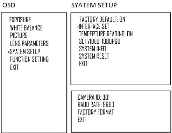
SYSTEM SETUP Menu
The SYSTEM SETUP menu is used to set the items related to the camera system.
FACTORY DEFAULT:
The menu is used to restore the factory settings.
INTERFACE SET:
This menu is used to set the following parameters:
CAMERA ID:
Factory Default Setting: 001
Use RS485 PELCO-D can control up to 255
cameras, camera ID from 001 to 255 has to be set.
Use RS422 VISCA protocol can control up to 7 cameras, camera ID from 1 to 7 has to be set.
BAUD RATE:
Factory Default Setting: 9600,
Select the baud rate from the following: 2400, 4800, 9600, 38400bps.
FACTORY FORMAT:
CAMERA ID: 001
BAUD RATE: 9600
text_image
OSD SYATEM SETUP EXPOSURE WHITE BALANCE PICTURE LENS PARAMETERS >SYATEM SETUP FUNCTION SETTING EXIT FACTORY DEFAULT: ON >INTERFACE SET TEMPERTURE READING: ON SDI VIDEO: 1080PGO SYSTEM INFO SYSTEM RESET EXIT CAMERA ID: 001 BAUD RATE: 9600 FACTORY FORMAT EXITNOTE:
- After the camera ID and Baud rate is set, to activate the new set camera ID and Baud rate, the camera has to be rebooted by powering the camera OFF and ON.
- For Dual-Output camera, the camera ID and Baud rate on IP web interface is auto-adjusted with the camera ID and Baud rate setting on the SDI side.
- Once you modified and saved the camera ID and baud rate setting on camera side, please modify the corresponding parameters on the keyboard side, otherwise the camera and keyboard will be unable to communicate.
SDI VIDEO:
SDI + IP True Dual Output: You can have parallel SDI and IP video output. Either SDI or IP video format can be set up independently for having dual output simultaneously.
- SDI output: Select the SDI video output format from the following:
B Class models: 1080P: 60/59.94/50/30/29.97/25; 1080I:60/59.94/50; 720P: 60/59.94/50/30/25.
S Class models: 1080P: 60/50/30/25; 720P: 60/50/30/25.
- IP output: For IP video output, please refer to User manual part two.
VIDEO FORMAT: SDI + IP True Dual Output:
The SDI video output and the IP video output can be configured independently. Each can be set to its own resolution. The IP and SDI can output separate video resolutions simultaneously.

flowchart
graph TD
    A["Network"] --> B["SDI 1080i59.94 1080p60*"]
    B --> C["Output to SDI"]
    style A fill:#f9f,stroke:#333
    style B fill:#ccf,stroke:#333
    style C fill:#cfc,stroke:#333
    note bottom of C: *Examples of independent / simultaneous resolution output for SDI and IP
SDI output options:
B-Class models:
• 1080P: 60/59.94/50/30/29.97/25
• 1080I:60/59.94/50; 720P: 60/50/30/25
S-Class models:
Follow these steps to change the video format:
SDI Video format:
- Set SDI video resolution by accessing the SDI OSD menu, and selecting SYSTEM SETUP
- Select the SDI VIDEO format you want to have from 1080P: 60/59.94/50/30/29.97/25; 1080I:60/59.94/50; 720P: 60/50/30/25.
- Wait for a while for camera new set video format being taken. It is normal that you cannot take the control of the interface while the video format is being changed. Once control has been recovered, reboot the camera by disconnecting the power, and then reconnecting the power.
IP Video format:
- Go to IP camera Web Interface
-
Select the Video/Audio tab
-
IP video resolution can be set to one of the following: 1080P60, 1080P30, 1080P25, 720P60, 720P30, 720P25
NOTE: For more information regarding setting the IP video format, please refer to PART TWO-Network Cameras User Manual
SYSTEM INFO:
CAMERA ID: Modify in the menu of "INTERFACE SET" BAUD RATE: Modify in the menu of "INTERFACE SET" SDI VIDEO: Modify in the menu of "INTERFACE SET" IP VIDEO: Modify in the menu of "INTERFACE SET" VERSION: The software version running on the camera
CAMERA ID: 01 BAUD RATE: 9600 SOI VIDEO: 1080P/30 SV: SON080B10020CA06
SYSTEM RESET:
Soft reboot to save the changes have been made and make the changes activated
EXIT: Push the joystick to the right to exit this level menu.
FUNCTION SETTING Menu
The FUNCTION SETTING menu is used to set the items related to the camera functionalities.
Note: The number of available presets may be limited by the head-ins, controllers, and DVRs that are connected to your dome system.
PRESETS SETUP:
Preset is to store the PTZ information (such as: Pan and Tilt positions, focal length etc.) under the specific condition, and call the camera PTZ quickly to shoot to the specified location that you want the camera to move to.
Note: Presets not only save desired image positions, various picture settings such as brightness, exposure values and other variables are also saved and stored.
EXPOSURE
WHITE BALANCE
PICTURE
LENS PARAMETERS
SYSTEM SETUP
FUNCTION SETTING
EXIT
Note: Pan and Tilt are not available on the FEX model.
The menu is used to manage the presets. Total of 220 presets can be managed.
PRESETS NUMBER:
The current preset number that you are managing.
SET NEW PRESET:
To set up (or overwrite) the preset of the preset shown under PRESET NUMBER
- Enter this setting menu, you will see "call preset 1 to end" flashing on the screen.
- Adjust the camera to the position that you want the preset to be
- Call the preset 1 using the keyboard to save the preset as the current position
DELETE PRESET:
With this option selected, push the joystick to the right to delete the preset shown under PRESET NUMBER preset.
EXIT: Push the joystick to the right to exit this level menu.
PRESETS SETUP
TOUR SETUP
PATTERN SETUP
IDLETIMER:003
IDLE ACTION : OFF
EXIT
PRESET NUMBER: DOI
PRESET MEMORY: ON
SET NEW PRESET
DELETE PRESET
EXIT
CALL PRESET I TO END
PRESET NUMBER: DOI
PRESET MEMORY: ON
SET NEW PRESET
DELETE PRESET
EXIT
There are pre-programmed functionalities of the camera have been setup with presets, means that these functionalities can be activated or triggered by running certain presets or setting certain presets. For example, run preset 95 is to turn on the OSD menu displayed on the screen, etc.
In order to use the special functions of the camera, the following presets are predefined for specific functions (You can find the default predefined preset at Web interface, Setup -> PTZ -> Advanced Settings):
| Preset number | Set / call | Function description |
| 54 | Set | Lens Reset |
| 55 | Call | Activate Backlight |
| Set | Deactivate Backlight | |
| 56 | Call | Activate auto shutter |
| Set | Deactivate auto shutter | |
| 57 | Call | Activate screen display |
| Set | Deactivate screen display | |
| 58 | Call | Activate Digital Zoom |
| Set | Deactivate Digital Zoom | |
| 59 | Call | Disable WDR |
| Set | Enable WDR | |
| 60 | Call | Auto Iris |
| Set | Manual Iris | |
| 61 | Call | Auto white balance |
| Set | Manual white balance | |
| 63 | Call | Image normal |
| Set | Image Flip | |
| 64 | Call | Color mode |
| Set | Black and white mode | |
| 65 | Call | Auto Day/Night Mode |
| 95 | Set | Open menu |
| 97 | Call | Start Patrol |
| Set | Set Patrol Route | |
| 99 | Call | Auto focus |
| Set | Manual focus |
TOUR SETUP:
The menu is used to manage the tours. Total of 4 tours can be managed
SEQUENCE NUMBER:
The current tour number that you are managing
DEFAULT DWELL:
Set the interval time between each of presets in the above tour, the value can be selected from 3 to 255 sec
| PRESETS SETUP>TOUR SETUPPATTERN SETUPIDLE TIMER : 003IDLE ACTION : OFFEXIT |
| SEQUENCE NUMBER: 00IDEFAULT DWELL: 255EDIT SEQUENCERUN CONTINUOUSLYEXIT |
EDIT SEQUENCE:
Set up the above tour.
- In the order of ① ② ③ ... ⑥, add each of preset and default dwell time to the tour.
- The tour path will be set based on the presets and default dwell have been set in step one.
| Preset Number | DEFAULT DWELL | Preset Number | DEFAULT DWELL | Preset Number | DEFAULT DWELL |
| 1 000 | 000 | 2 000 | 000 | 3 000 | 000 |
| 4 000 | 000 | 5 000 | 000 | 6 000 | 000 |
| 000 | 000 | 000 | 000 | 000 | 000 |
| 000 | 000 | 000 | 000 | 000 | 000 |
| ... | ... | ... | ... | ... | ... |
RUN CONTINOUSELY: start the tour that has been set.
EXIT: Push the joystick to the right to exit this level menu.
PATTERN SETUP:
A pattern is a memorized, repeating series of pan, tilt, zoom, and preset functions that can be recalled with a command from a controller or automatically by a programmed function (alarm, park, event, or power-up).
The menu is used to manage the patterns. Total of 4 patterns can be managed
PATTERN NUMBER:
The current pattern number that you are managing
PATTERN NUMBER: 001
RECORD NEW PATTERN
RUN CONTINUOUSLY
EXIT
RECORD NEW PATTERN:
Set up the above pattern
- Push the joystick to the right to enter this setting menu
- Move the camera to the start position you want, and then call the preset 1 to save
- Move the camera to each position you want to record the pattern, and then call the preset 1 to end
- Finished
RUN CONTINIUSELY: start the above pattern.
EXIT: Push the joystick to the right to exit this level menu.
IDLE TIMER:
If the camera stays in No-operation for certain amount of IDLE Time, the camera would take action automatically.
The menu is used to set the IDLE time, and value can be selected from 0 to 255 sec.
PRESETS SETUP
TOUR SETUP
PATTERN SETUP
IDLETIMER:003
IDLE ACTION : OFF
EXIT
IDLE ACTION:
After the IDLE time, the camera starts the IDLE action automatically.
Even if the idle time's value is set to 0, or during the IDLE time, manual operation will always have the priority to the response.
The menu is used to select the IDLE action.
The IDLE action can be selected from the following:
EXIT: Push the joystick to the right to exit this level menu.
EXIT
Push the joystick to the right to exit the menu. All setting modifications will be discarded, and will not be applied
Use IP Video Output
To use IP video output, please refer to PART TWO - NETWORK CAMERA USER MANUAL
Setting Camera over the LAN
To view and configure your camera via the local area network (LAN), you need to install the Controls (VideoPlugin) for the first time to login the camera IP interface.
- Connect your camera and your PC as shown in the figure below to ensure the routing is available.
- Modify the camera settings if necessary, including its IP address and subnet mask.
NOTE
- Default IP address is "192.168.0.13", default username is "admin", and default password is "admin".
Accessing your camera
Before you begin, please check:
- Make sure the self-test is completed.
- Your camera is operating properly and connected to the network.
- The IP camera/encoder only supports IE11, ensure that the PC client you are using is installed with Internet Explorer 11.
- Open Internet Explorer on your PC.
- In the address bar, input the IP address plus the port number of your camera (default IP is 192.168.0.13, so the login URL should be http://192.168.0.13), then press Enter to open the login page.
- Enter the username (default is "admin") and password (default is "admin")
- Click Login button to access to IP video interface.
To use IP video output, please refer to PART TWO - NETWORK CAMERA USER MANUAL
Menu Configuration
The menus of camera are configured as described below. OSD Menu Configuration
| Menu | EXPOSURE | MODE | FULL AUTO | IRIS | Null |
| GAIN | Null | ||||
| SHUTTER | Null | ||||
| BRIGHT | Null | ||||
| BACKLIGHT MODE | OFF, ON | ||||
| DEFOG | OFF, ON | ||||
| EX-COMP MODE | ON, OFF | ||||
| EX-COMP LEVEL | -10.5dB, -9dB, -7.5dB, -6dB, -4.5dB, -3dB, -1.5dB, 0dB, 1.5dB, 3dB, 4.5dB, 6dB, 7.5dB, 9dB, 10.5dB | ||||
| HIGH SENSITIVITY | OFF, ON | ||||
| SLOW AE | 1 to 48 | ||||
| SLOW SHUTTER | OFF, ON | ||||
| GAIN LIMIT | 10.7dB, 14.3dB, 17.8dB, 21.4dB, 25.0dB, 28.6dB, 32.1dB, 35.7dB, 39.3dB, 42.8dB, 46.4dB, 50dB | ||||
| MIN. SHUTTER MODE | OFF, ON | ||||
| MIN. SHUTTER LIMIT | 1/1, 1/2, 1/4, 1/8, 1/15, 1/30, 1/60, 1/90, 1/100, 1/125, 1/180, 1/250, 1/350, 1/500, 1/725, 1/1K, 1/1.5K, 1/2K, 1/3K, 1/4K, 1/6K, 1/10K | ||||
| EXIT | |||||
| MANUAL | IRIS | CLOSE, F1.6, F2.0, F2.4, F2.8, F3.4, F4, F4.8, F5.6, F6.8, F8, F9.6, F11, F14 | |||
| GAIN | 0dB, 3.6dB, 7.1dB, 10.7dB, 14.3dB, 17.8dB, 21.4dB, 25dB, 28.6dB, 32.1dB, 35.7dB, 39.3dB, 42.8dB, 46.4dB, 50dB | ||||
| SHUTTER | 1/1, 1/2, 1/4, 1/8, 1/15, 1/30, 1/60, 1/90, 1/100, 1/125, 1/180, 1/250, 1/350, 1/500, 1/725, 1/1K,1/1.5K, 1/2K, 1/3K, 1/4K, 1/6K, 1/10K | ||||
| BRIGHT | Null | ||||
| BACKLIGHT MODE | Null | ||||
| DEFOG | Null | ||||
| EX-COMP MODE | ON, OFF | ||||
| EX-COMP LEVEL | -10.5dB, -9dB, -7.5dB, -6dB, -4.5dB, -3dB, -1.5dB, 0dB, 1.5dB, 3dB, 4.5dB, 6dB, 7.5dB, 9dB, 0.10dB | ||||
| HIGH SENSITIVITY | OFF, ON | ||||
| SLOW AE | Null | ||||
| SLOW SHUTTER | OFF, ON | ||||
| GAIN LIMIT | 10.7dB, 14.3dB, 17.8dB, 21.4dB, 25.0dB, 28.6dB, 32.1dB, 35.7dB, 39.3dB, 42.8dB, 46,4dB, 50dB | ||||
| MIN. SHUTTER MODE | OFF | ||||
| MIN. SHUTTER LIMIT | 1/1, 1/2, 1/4, 1/8, 1/15, 1/30, 1/60, 1/90, 1/100, 1/125, 1/180, 1/250, 1/350, 1/500,1/725, 1/1K, 1/1.5K, 1/2K, 1/3K, 1/4K, 1/6K, 1/10K | ||||
| EXIT | |||||
| IRIS PRIOR | IRIS | CLOSE, F1.6, F2.0, F2.4, F2.8, F3.4, F4, F4.8, F5.6, F6.8, F8, F9.6, F11, F14 | |||
| GAIN | Null | ||||
| SHUTTER | Null | ||||
| BRIGHT | Null | ||||
| BACKLIGHT MODE | Null | ||||
| DEFOG | Null | ||||
| EX-COMP MODE | ON, OFF | ||||
| EX-COMP LEVEL | -10.5dB, -9dB, -7.5dB, -6dB, -4.5dB, -3dB, -1.5dB,0dB, 1.5dB, 3dB, 4.5dB, 6dB, 7.5dB, 9dB, 10.5dB | ||||
| HIGH SENSITIVITY | OFF, ON | ||||
| SLOW AE | Null | ||||
| SLOW SHUTTER | OFF, ON | ||||
| GAIN LIMIT | 10.7dB, 14.3dB, 17.8dB, 21.4dB, 25.0dB, 28.6dB, 3.2.1dB, 35.7dB, 39.3dB, 42.8dB, 46.4dB, 50dB | ||||
| MIN. SHUTTER MODE | OFF | ||||
| MIN. SHUTTER LIMIT | 1/1, 1/2, 1/4, 1/8, 1/15, 1/30, 1/60, 1/90, 1/100, 1/125, 1/180. 1/250, 1/350, 1/500, 1/725, 1/1K, 1/1.5K, 1/2K, 1/3K, 1/4K, 1/6K, 1/10K | ||||
| EXIT | |||||
| SHUTTER | IRIS | Null | ||
| GAIN | Null | |||
| SHUTTER | 1/1, 1/2, 1/4, 1/8, 1/15, 1/30, 1/60, 1/90, 1/100, 1/125, 1/180, 1/250, 1/350, 1/500, 1/725, 1/1K, 1/1.5K, 1/2K, 1/3K, 1/4K, 1/6K, 1/10K | |||
| BRIGHT | Null | |||
| BACKLIGHT MODE | Null | |||
| DEFOG | Null | |||
| EX-COMP MODE | ON, OFF | |||
| EX-COMP LEVEL | -10.5dB, -9dB, -7.5dB, -6dB, -4.5dB, -3dB, -1.5dB, 0dB, 1.5dB, 3dB, 4.5dB, 6dB, 7.5dB, 9dB, 10.5dB | |||
| HIGH SENSITIVITY | OFF, ON | |||
| SLOW AE | Null | |||
| SLOW SHUTTER | OFF, ON | |||
| GAIN LIMIT | 10.7dB, 14.3dB, 17.8dB, 21.4dB, 25.0dB, 28.6dB, 32.1dB, 35.7dB, 39.3dB, 42.8dB, 46.4dB, 50dB | |||
| MIN. SHUTTER MODE | OFF | |||
| MIN. SHUTTER LIMIT | 1/1, 1/2, 1/4, 1/8, 1/15, 1/30, 1/60, 1/90, 1/100, 1/125, 1/180, 1/250, 1/350, 1/500, 1/725, 1/1K,1/1.5K, 1/2K, 1/3K, 1/4K, 1/6K, 1/10K | |||
| EXIT | ||||
| BRIGHT | IRIS | Null | ||
| GAIN | Null | |||
| SHUTTER | Null | |||
| BRIGHT | 0 to 31 | |||
| BACKLIGHT MODE | Null | |||
| DEFOG | Null | |||
| EX-COMP MODE | ON, OFF | |||
| EX-COMP LEVEL | -10.5dB, -9dB, -7.5dB, -6dB, -4.5dB, -3dB, -1.5dB, 0dB, 1.5dB, 3dB, 3.5dB, 4.5dB, 6dB, 7.5dB, 9dB, 10.5dB | |||
| HIGH SENSITIVITY | OFF, ON | |||
| SLOW AE | Null | |||
| SLOW SHUTTER | OFF, ON | |||
| GAIN LIMIT | 10.7dB, 14.3dB, 17.8dB,21.4dB, 25.0dB, 28.6dB, 32.1dB, 35.7dB, 39.3dB, 42.8dB, 46.4dB, 50dB | |||
| MIN. SHUTTER MODE | OFF | |||
| MIN. SHUTTER LIMIT | 1/1, 1/2, 1/4 , 1/8 , 1/15 , 1/30 , 1/60 , 1/90 , 1/100 , 1/125 , 1/180 , 1/250 , 1/350 , 1/500 , 1/725 , 1/1K , 1/1.5K , 1/2K , 1/3K , 1/4K , 1/6K , 1/10K | |||
| EXIT | ||||
| WHITE BALANCE | MODE | ATW | USER DEFINED | R: Null |
| USER DEFINED | B: Null | |||
| EXIT | ||||
| OUTDOOR | USER DEFINED | R: Null | ||
| USER DEFINED | B: Null | |||
| EXIT | ||||
| INDOOR | USER DEFINED | R: Null | ||
| USER DEFINED | B: Null | |||
| EXIT | ||||
| AUTO | USER DEFINED | R: Null | ||
| USER DEFINED | B: Null | |||
| EXIT | ||||
| SVL OUTDOOR AUTO | USER DEFINED | R: Null | ||
| USER DEFINED | B: Null | |||
| EXIT | ||||
| SVL | USER DEFINED | R: Null | ||
| USER DEFINED | B: Null | |||
| EXIT | ||||
| SVL AUTO | USER DEFINED | R: Null | ||
| USER DEFINED | B: Null | |||
| EXIT | ||||
| OUTDOOR AUTO | USER DEFINED | R: Null | ||
| USER DEFINED | B: Null | |||
| EXIT | ||||
| USER | USER DEFINED | R: 0 to 255 | ||
| USER DEFINED | B: 0 to 255 | |||
| EXIT | ||||
| OPW | USER DEFINED | R: Null | ||
| USER DEFINED | B: Null | |||
| EXIT | ||||
| PICTURE | SHARPNESS | 0 to 15 |
| EFFECT | OFF, B&W, NEG.ART | |
| COLOR GAIN | 1 to 15 | |
| COLOR HUE | 1 to 15 | |
| FLIP | OFF, ON | |
| MIRROR | OFF, ON | |
| NOISE REDUCTION | ||
| Mode | OFF, 2D/3D, 5, 4, 3, 2, 1 | |
| 2D | OFF, 5, 4, 3, 2, 1 | |
| 3D | OFF, 5, 4, 3, 2, 1 | |
| EXIT | ||
| STABILIZER | OFF, ON | |
| STABLE ZOOM | OFF, ON | |
| GAMMA | 0, 1 | |
| GAMMA OFFSET | -49 to -64, 0 to 64 | |
| LOW-ILLUM. CHROMA | OFF, 3, 2, 1 | |
| DE-FLICKER | OFF, ON | |
| WDR | OFF, ON, VE ON | |
| EXIT | ||
| LENS PARAMETERS | ZOOM | |
| DIGITAL ZOOM | OFF, ON | |
| ZOOM OSD DISPLAY | OFF, ON | |
| EXIT | ||
| AUTO FOCUS | ||
| AF SENSITIVITY | NORMAL, LOW | |
| AF MODE | NORMAL AF, ZOOM TRIGGER, INTERVAL AF | |
| EXIT | ||
| MANUAL FOCUS | ||
| MF SPEED | FIXED SPEED, VARIABLE SPEED, | |
| VARIABLE SPEED | (Adjustable when MF SPEED set to VARIABLE SPEED MODE) | |
| EXIT | ||
| NEAR LIMIT | 11cm, 30cm, 0.8m, 1.2m, 1.4m, 1.65m, 2m, 2.5m, 3.1m, 4.2m, 6m, 10m, 20m, OVER | |
| JOYSTICK RECOVER | NONE, AF-AI, A/I, A/F | |
| A/F RECOVER TIME | 0 to 255 | |
| A/I RECOVER TIME | 0 to 255 | |
| DAY/NITE MODE | AUTO, DAY, NITE | |
| LASER SETUP | ON, OFF | |
| ZOOMING SPEED | 1 to 8 | |
| EXIT | ||
| SYSTEM SETUP | FACTORYDEFAULT | Succeed |
| INTERFACE SET | ||
| CAMERA ID | 001 to 255 | |
| BAUD RATE | 2400, 4800, 9600, 19200 | |
| FACTORY FORMAT | Succeed | |
| LOW LATENCY | ON, OFF | |
| EXIT | ||
| TEMPERATURE READING | OFF, ON | |
| SDI VIDEO | 1080p @60@59.94@50@30@29.97@251080i @60@59.94@50, 720p @60@59.94@50@30@25 | |
| SYSTEM INFO | ||
| CAMERA ID | 001 | |
| BAUD RATE | 9600 | |
| SDI VIDEO | 1080p60 | |
| SV | SVB0H080310020AA003T9 | |
| SYSTEM RESET | ||
| EXIT | ||
| FUNCTION SETTING | PRESETS SETUP | |
| PRESET NUMBER | 001 to 220 | |
| PRESET MEMORY | ON, OFF | |
| SET NEW PRESET | CALL PRESET 1 TO END | |
| DELETE PRESET | ||
| EXIT | ||
| TOUR SETUP | ||
| SEQUENCE NUMBER | 001 to 004 | |
| DEFAULT DWELL | 003 to 255 | |
| EDIT SEQUENCE | 000-000, SAVE & EXIT, CANCEL | |
| RUN CONTINUOUSLY | ||
| EXIT | ||
| PATTERN SETUP | ||
| PATTERN NUMBER | 001 to 004 | |
| RECORD NEW PATTERN | MOVE TO START POINT CALL PRESET 1 TO END | |
| RUN CONTINUOUSLY | ||
| EXIT | ||
| IDLE TIMER | 000 to 255 | |
| IDLE ACTION | OFF, PAIT-4, PAIT-3, PAIT-2, PAIT-1, TOUR-4, TOUR-3, TOUR-2, TOUR-1, PRE001 to PRE220, | |
| EXIT | ||
| EXIT | ||
Dimensions
Unit: mm
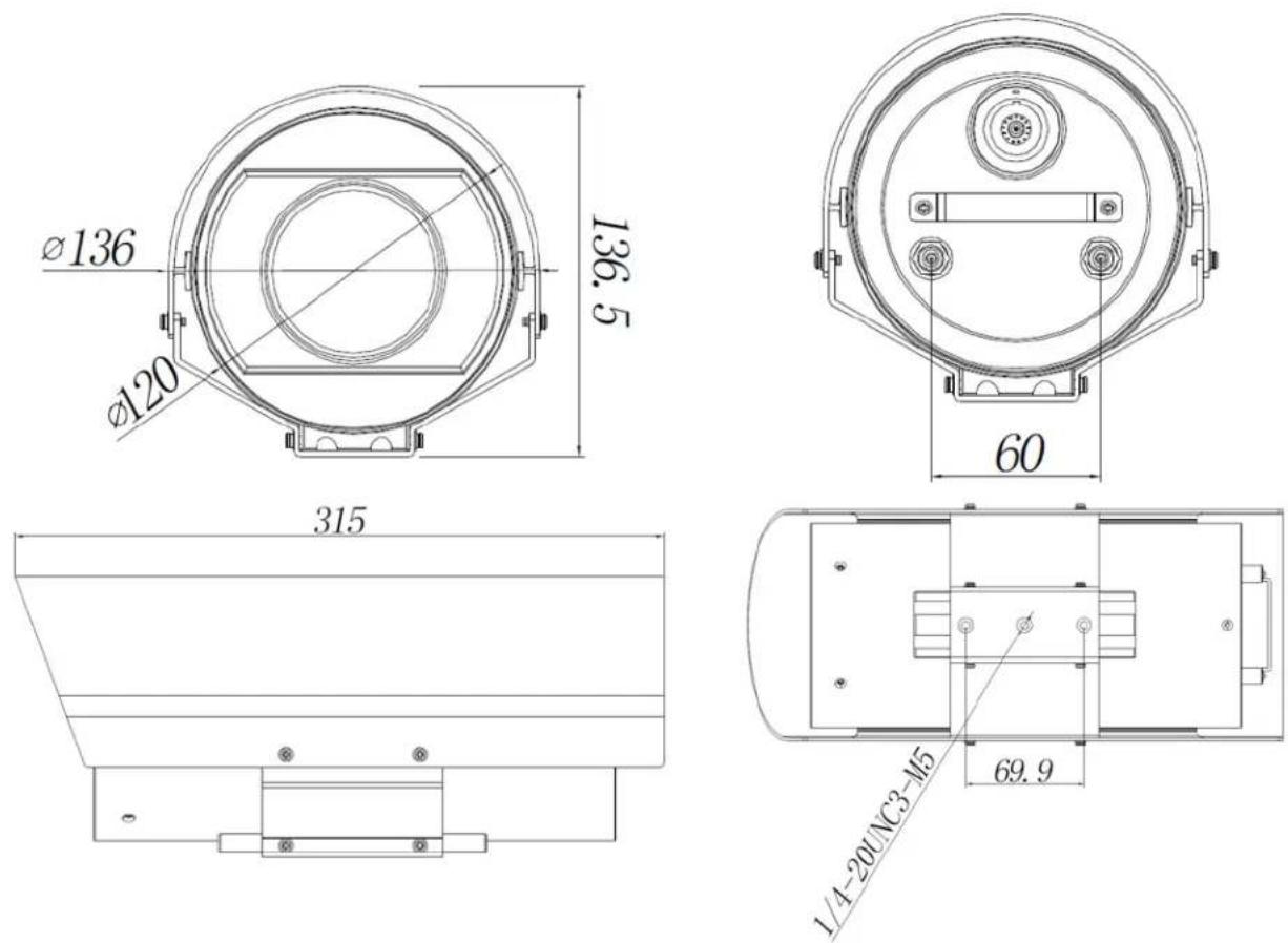
BOLiN
TECHNOLOGY
www.bolintechnology.com
2082 TECHNOLOGY LLC dba
BOLIN TECHNOLOGY