
AD-TVAC-CM-B - TV Stand Atdec - Free user manual and instructions
Find the device manual for free AD-TVAC-CM-B Atdec in PDF.

| Product Type | AV Cart Camera Mount |
| Brand | Atdec |
| Model | AD-TVAC-CM-B |
| Weight Capacity | 0–5 kg (0–11 lbs) |
| Compatible Carts | AD-TVC-20, AD-TVC-45, AD-TVC-70A, AD-TVC-75 |
| Material | Metal |
| Mounting Type | Clamp (AD-TVC-70A) or screw attachment to cart column |
| Included Components | Upright Bracket, Camera Shelf, M5x8 Screws (x2), M5x10 Screws (x2), M6x10 Screws (x2), M6 Flange Nut, Washers (x2), 5mm Hex Key, 4mm Hex Key, Spanner |
| Required Tools | Phillips Head Screwdriver |
| Installation | Professional installation recommended; two-person suggested |
| Maintenance | Tighten fasteners and check security every 3 months |
| Cleaning | Wipe with a dry cloth; avoid abrasive cleaners |
| Safety Warning | Risk of serious injury if children climb on cart; secure devices properly |
| Outdoor Use | Not suitable for outdoor use |
| Spare Parts & Repairability | Contact distributor for spare parts; no user-serviceable parts |
Frequently Asked Questions - AD-TVAC-CM-B Atdec
User questions about AD-TVAC-CM-B Atdec
0 question about this device. Answer the ones you know or ask your own.
Ask a new question about this device
Download the instructions for your TV Stand in PDF format for free! Find your manual AD-TVAC-CM-B - Atdec and take your electronic device back in hand. On this page are published all the documents necessary for the use of your device. AD-TVAC-CM-B by Atdec.
USER MANUAL AD-TVAC-CM-B Atdec
AV Cart Camera Mount
natural_image
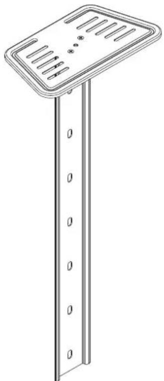
Technical line drawing of a vertical support structure with slots and mounting holes (no text or symbols)COMPONENT CHECKLIST

natural_image
Line drawing of a rectangular object with circular holes, no text or symbols presentA
Upright Bracket

B
Camera
Shelf

C
M5x8 Screw (x2)

D
5mm
Hex Key

E
4mm
Hex Key

F
Spanner

G
M5x10
Screw
(x2)

H
M6x10
Screw
(x2)

1
M6
Flange
Nut

J
Washer (×2)

REQUIRED TOOLS
• Phillips Head Screwdriver
WEIGHT RANGE
0 - 5kg (0 - 11lbs)
IMPORTANT INFORMATION
! Please ensure this product is installed as per these installation instructions.
! Please ensure your preferred device is securely fastened to the mount prior to use or movement.
! The manufacturer accepts no responsibility for incorrect installation.
! Failure to assemble this product correctly may cause serious injury/death during or following installation.
! This product should only be installed by professional installers of good mechanical aptitude, who fully understand these
instructions and the consequences of incorrect installation.
! Do not over tighten screws.
! Two person installation is recommended.
! Product not suitable for use outdoors
! After installation is complete check to verify that AV Cart is secure and safe for use.
! Curved monitors, deep devices (such as all-in-one PCs), VESA mounted accessories (such as mini PC brackets and mounts), and offset VESA locations exert additional leverage that can exceed the capacity of the mount even though the monitor weight may be within the stated range. Please contact Atdec if you would like further information.
! WARNING! Death or serious injury may occur when children climb on audio and/or video equipment furniture. A remote control or toys placed on the cart may encourage a child to climb on the cart and as a result the cart may tip over on to the child.

1. Construct the Camera Mount Assembly
Attach Camera Shelf B to Upright Bracket A with M5 Screws C.
For AD-TVC-70A, loosen the screws on the pre-installed silver clamp plate using Hex Key D.
Leave a 4mm gap between the clamp plate and upright bracket.
For AD-TVC-20, AD-TVC-45 and AD-TVC-75, remove the silver clamp plate completely.
Attach Camera Shelf B to Upright Bracket A with M5 Screws C.
For AD-TVC-70A, loosen the screws on the pre-installed silver clamp plate using Hex Key D.
Leave a 4mm gap between the clamp plate and upright bracket.
For AD-TVC-20, AD-TVC-45 and AD-TVC-75, remove the silver clamp plate completely.

A - FOR AD-TVC-20 CART
A2. Attach the Camera Mount Assembly to the cart
A2.1. Remove the rubber cable management grommet from the slot on the cart.
A2.2. Determine the two holes needed on Upright Bracket A to hold the Camera Mount Assembly at the desired height.
A2.3. With assistance, hold the Camera Mount Assembly sideways (as illustrated) and align the lower of the two holes with the hole directly above the cable management slot on the cart.
A2.4. Insert M6 Screw H with Washer J through Upright Bracket A and into the hole on the cart.
A2.5. Attach M6 Flange Nut I to M6 Screw H inside the cart column through the cable management slot. Tighten using 5mm Hex Key D.
TIP: Use Spanner F to support M6 Flange Nut I whilst tightening M6 Screw H.

natural_image
Technical line drawing of a mechanical assembly with mounting bracket and vertical supports (no text or symbols)A3. Secure the Camera Mount Assembly to the cart
A3.1. Rotate the camera mount assembly to its final position and secure it to the top hole on the cart using M6 Screw H, Washer J and 5mm Hex Key D.
A3.2. Install your preferred device. Ensure it is secured using the screw hole on Camera Shelf B or straps.

natural_image
Technical line drawing of a mechanical assembly with spring-loaded components and a rotating arrow indicating motion (no text or symbols)B - FOR AD-TVC-45 CART
B2. Attach the Camera Mount Assembly to the cart
B2.1. Fasten the Camera Mount Assembly to the Cart at the desired height using M5 Screws G, Washers J and 4mm Hex Key E.
B2.2. Install your preferred device. Ensure it is secured using the screw hole on Camera Shelf B or straps.

C - FOR AD-TVC-70A CART
C2. Remove Top Cap from the cart

natural_image
Technical line drawing of a mechanical assembly with mounting brackets and a central component (no text or symbols)C3. Attach Camera Mount
C3.1. Insert the silver clamp plate (attached to Upright Bracket A) into the top of the rear mounting channel of the upper column of the cart.
C3.2. Move the Camera Mount Assembly to the desired height and secure it by tightening the screws using 5mm Hex Key D.
C3.3. Install your preferred device. Ensure it is secured using the screw hole on Camera Shelf B or straps.

C4. Replace Top Cap

natural_image
Technical line drawing of a mechanical assembly with mounting brackets and a central component (no text or symbols)D - FOR AD-TVC-75 CART
D2. Attach camera mount assembly to cart
D2.1. Fasten the Camera Mount Assembly to the Cart at the desired height using M5 Screws G, Washers J and 4mm Hex Key E.
D2.2. Install your preferred device. Ensure it is secured using the screw hole on Camera Shelf B or straps.

MAINTENANCE
- Tighten fasteners and check if the cart is secure and safe to use at regular intervals (at least every three months.)
- Please contact your distributor if you have any questions.


- AV Cart Camera Mount
- REQUIRED TOOLS
- WEIGHT RANGE
- IMPORTANT INFORMATION
- Construct the Camera Mount Assembly
- A - FOR AD-TVC-20 CART
- A2. Attach the Camera Mount Assembly to the cart
- A3. Secure the Camera Mount Assembly to the cart
- B - FOR AD-TVC-45 CART
- B2. Attach the Camera Mount Assembly to the cart
- C - FOR AD-TVC-70A CART
- C2. Remove Top Cap from the cart
- C3. Attach Camera Mount
- C4. Replace Top Cap
- D - FOR AD-TVC-75 CART
- D2. Attach camera mount assembly to cart
- MAINTENANCE
Brand : Atdec
Model : AD-TVAC-CM-B
Category : TV Stand