
TH-TVCH - TV Stand Atdec - Free user manual and instructions
Find the device manual for free TH-TVCH Atdec in PDF.

| Product Type | Mobile TV Cart / Stand |
| Brand | Atdec |
| Model | TH-TVCH |
| Maximum Load Capacity | 125 kg (275 lbs) |
| VESA Mounting Hole Pattern | 200x200 mm to 450x450 mm (up to 800x800 mm with extensions) |
| Orientation Support | Landscape and portrait |
| Height Adjustment | Yes (manual adjustment via column) |
| Tilt Adjustment | Yes (requires spanners) |
| Castors | 4 locking castors (included) |
| Cable Management | Yes (integrated cable management) |
| Material | Steel |
| Color | Black |
| Assembly Required | Yes (detailed instructions included) |
| Upright Extensions Included | Yes (for wider VESA patterns) |
| Bracket Type | Adjustable brackets with slide mechanism |
| Compatible Screen Sizes | Most flat screens up to 125 kg |
| Maintenance | Wipe with damp cloth; check fasteners regularly |
| Safety Note | Maximum load must not be exceeded; install per instructions |
| Warranty | Not specified; contact Atdec for details |
Frequently Asked Questions - TH-TVCH Atdec
User questions about TH-TVCH Atdec
0 question about this device. Answer the ones you know or ask your own.
Ask a new question about this device
Download the instructions for your TV Stand in PDF format for free! Find your manual TH-TVCH - Atdec and take your electronic device back in hand. On this page are published all the documents necessary for the use of your device. TH-TVCH by Atdec.
USER MANUAL TH-TVCH Atdec
HARDWARE

IMPORTANT INFORMATION:
! IMPORTANT - Install Telehook TV Cart as per installation instruction.
! This product supports a maximum load of 125kg (275lbs.).
This product supports VESA Mounting Hole Configurations: From 200mm to 450mm wide (800mm with extensions) and from 200mm to 450mm high (800mm high with extensions).
! The manufacturer accepts no responsibility for incorrect installation.
Step 1. Check Components
Check you have received against the component checklist and hardware above.
Step 2. Assemble Base

2.1 Mount all castors and tighten with caster spanner.
Step 3. Mount Column to Base

Step 4. Adjust Height Step 5. Attach Uprights

Step 6. Choose Screen Orientation
6.1 The TV Cart supports both Landscape and Portrait orientations. The method of attaching the screen will depend on the screen's VESA hole configuration.
Before moving to the next step, measure dimensions X & Y as shown below.

Step 7. Attach Fixings to Screen

If dimension X is 200mm
Insert Socket Head Bolt straight into the screen ensuring that there is a 3-5mm gap.
If dimension X is from 300mm to 450mm
Mount the Brackets onto the back taking note to leave the bottom bracket loose so that it can slide.
If dimension X is from 450mm to 800mm
Mount the Brackets with extensions onto the back taking note to leave the bottom bracket loose so that it can slide.
If dimension Y is from 200mm to 450mm skip Step 8 and go straight to Step 9
If dimension Y is from 450mm to 800mm mount the Upright extensions.
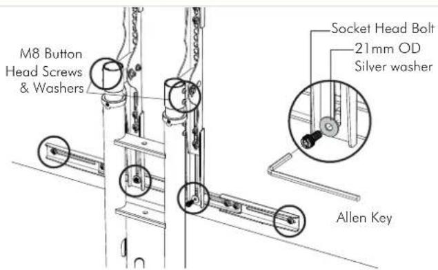
Step 8. Mount Upright Extensions

natural_image
Technical diagram of a mechanical assembly with two views, showing components and a magnified inset (no text or labels)
Step 9. Mount Screen


natural_image
Pure mechanical diagram showing a lever and pivot mechanism without any text or symbols9.2 Insert bolts through key holes and lower to secure.
9.3 Insert the remaining socket head bolts and washers on to the bottom bracket before fastening all of the screws.
Step 10. Adjust Tilt Step 11. Cable management

10.1 Using the provided spanners to adjust tilt, hold down the nut on the inside of the upright whilst turning the bolt on the outside.

natural_image
Technical line drawing of a mechanical assembly with mounting bracket and vertical panel (no text or symbols)
Installation Complete


Brand : Atdec
Model : TH-TVCH
Category : TV Stand