CN-R50mm T1.3 L F - Lens CANON - Free user manual and instructions
Find the device manual for free CN-R50mm T1.3 L F CANON in PDF.

User questions about CN-R50mm T1.3 L F CANON
0 question about this device. Answer the ones you know or ask your own.
Ask a new question about this device
Download the instructions for your Lens in PDF format for free! Find your manual CN-R50mm T1.3 L F - CANON and take your electronic device back in hand. On this page are published all the documents necessary for the use of your device. CN-R50mm T1.3 L F by CANON.
USER MANUAL CN-R50mm T1.3 L F CANON
Read this operation manual before using the product.
ENG
NOTE
This lens is a full manual lens for shooting movies.
Depending on the camera attached or the function used, the lens may not operate properly or the indications may not be correct.
In addition, do not operate the lens during initialization of the camera settings.
For other latest product information, please check our website.
CONTENTS
GENERAL SAFETY INFORMATION ......E4
PRODUCT LIST.....E8
NAMES OF PARTS ......E9
ATTACHING AND DETACHING THE LENS ....E10
AVAILABLE ACCESSORIES.....E12
DIMENSIONS OF PARTS ......E13
SPECIFICATIONS ......E14
EXTERNAL VIEW.....E19
GENERAL SAFETY INFORMATION
The safety warnings and cautions provided on the product or in this operation manual must be observed. Failure to observe these warnings and cautions may result in injury or accident.
Read this operation manual carefully to familiarize yourself with its contents and ensure that you can operate the product properly. Also, store this manual in a safe place where it can easily be referenced whenever necessary.
This operation manual uses the following symbols and terms to identify hazards in order to prevent accidents.

WARNING
This indicates a potentially hazardous situation which, if not heeded, may result in death or serious injury to you or others. Be sure to heed all warning notices to ensure safe operation at all times.

CAUTION
This indicates a potentially hazardous situation which, if not heeded, may result in a minor injury to you or others, or damage to property. Be sure to heed all caution notices to ensure safe operation at all times.
NOTE
This indicates cautions and recommendations for operation. It contains information which, if not heeded, may result in this product failing to function properly.
These notices also contain useful information for operation.
HANDLING THE PRODUCT

WARNING
Do not stare at the sun or other bright objects through the lens. It may injure your eyes.

CAUTION
- Ensure that all mountings are securely tightened. If a mounting becomes loose, parts may fall off and cause injury.
- Inspect mountings regularly (about every six months to one year) to ensure they are securely tightened. If a mounting becomes loose, parts may fall off and cause injury.
NOTE
- Do not expose the lens to strong impact. Striking or dropping the lens may cause the malfunction of the product.
- Take measures to avoid sudden changes in temperature where the lens is used, which may prevent operation temporarily if condensation forms in the lens.
DEALING WITH ABNORMALITIES

WARNING
If any of the following situations occurs, immediately dismount the lens from the camera and contact your Canon sales representative or dealer.
- Smoke, fumes, or unusual noises
- Entry of foreign objects (such as liquid or metal objects) inside the product
MAINTENANCE AND INSPECTION
NOTE
- Clean off any dust on the lens surface using a lens blower or a soft lens brush. In case of getting fingerprints or stains on the lens, use a clean cotton cloth moistened with commercial lens cleaning fluid, or use lens cleaning paper. Gently wipe in a spiral pattern from the center of the lens. Be careful not to rub dust across the lens, which may scratch the lens surface.
- Routine inspection about once a year is recommended, depending on the conditions and environment of use. Request overhaul, if needed.
STORAGE

WARNING
Always attach the lens cap, hood cap, dust cap or covers before storage. Storing the lens without the caps or covers attached poses a risk of fire if the lens concentrate light in direct sunlight.
NOTE
Immediately wipe off any moisture on the lens from misty or foggy environments, using a dry cloth. Seal the lens in a plastic bag with a desiccant (preferably new) to prevent moisture inside. Otherwise it may cause the mold or the malfunction of the product.
TO THE CUSTOMER
- Canon shall bear no responsibility for damage resulting from improper operation of this product by the customer.
- Canon shall make no guarantees about the product quality, functions, or operation manual and its marketability and suitability for the customer's purpose. Moreover, Canon shall bear no responsibility for any damage, direct or incidental, that results from usage for the customer's purpose.
- The product specifications, configuration, and appearance are subject to change without prior notice.
- For further information on repairs, maintenance, or adjustments not mentioned in this operation manual, contact your Canon sales representative or dealer.
- Note that Canon may be unable to undertake servicing or repair of a product if it is modified without consulting Canon or your Canon sales representative.
All rights reserved.
No part of this operation manual may be reproduced or copied in any form or by any means without the written permission of Canon Inc.
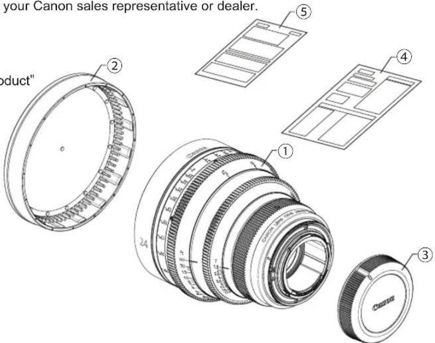
PRODUCT LIST
Make sure all of the following items are included in the packing box.
If you find any item missing, please contact your Canon sales representative or dealer.
① Lens body
② Lens cap
③ Rear lens cap
④ Operation Manual "Before Using The Product"
⑤ Operation Manual "Regulations"
text_image
your Canon sales representative or dealer. ① ② ③ ④ ⑤ ⑥ 24 6.5 x 5.5 x 4.5 x 3.5 x 2.5 x 1.5 x 0.5 x 0.2 x 0.1 x 0.05 x 0.02 x 0.01 x 0.005 x 0.002 x 0.001 x 0.0005 x 0.0002 x 0.0001 x 0.00005 x 0.00002 x 0.00001 x 0.000005 x 0.000002 x 0.000001 x 0.0000005 x 0.0000002 x 0.0000001 x 0.00000005 x 0.00000002 x 0.00000001 x 0.000000005 x 0.000000002 x 0.000000001 x 0.000000001 x 0.00The illustrations in this manual show CN-R24mm T1.5 L F unless otherwise specified.
The shapes of product may vary depending on models and specifications.
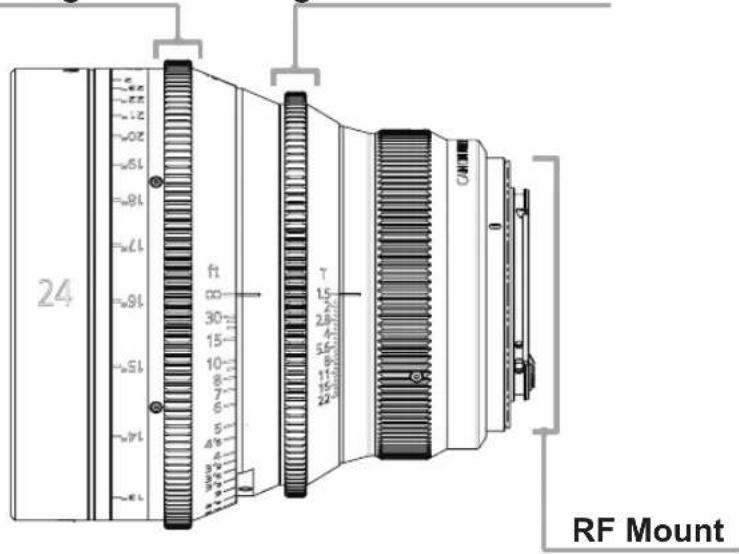
NAMES OF PARTS
Focus drive gear Iris drive gear
text_image
24 ft 30 15 10 8 7 6 5 4 3 2 1 RF MountATTACHING AND DETACHING THE LENS
Set the camera's power switch to OFF when attaching or detaching the lens. Refer to your camera's instructions for details on attaching and detaching the lens.
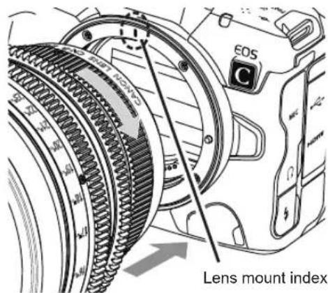
Attaching the Lens
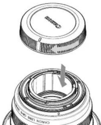
1 Detach the rear lens cap
Detach the rear lens cap by turning it as shown by the arrows.

text_image
CANON LENS DES VOLT Lens mount index2 Attach the lens
Align the lens mount indexes of the lens and camera, and turn the lens as shown by the arrows until you hear a click.
text_image
€05 C Lens mount indexDetaching the Lens
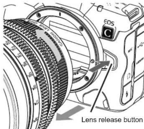
1 Detach the lens
Turn the lens as shown by the arrows while pressing the camera's lens release button. Detach the lens once it has stopped turning.
text_image
EOS C Lens release button2 Attach the rear lens cap
Attach the rear lens cap by turning it as shown by the arrows.
natural_image
Technical illustration of a camera lens assembly showing top and side views (no text or symbols)NOTE
- Attach the lens cap before detaching the lens from the camera.
• After detaching the lens, place the lens with the rear end up to prevent the lens surface and contacts from getting scratched. - If the contacts get soiled, scratched, or have fingerprints on them, corrosion or faulty connections can result. The camera and lens may not operate properly.
- If the contacts get soiled or have fingerprints on them, clean them with a soft cloth.
AVAILABLE ACCESSORIES
A variety of professional camera accessories compatible with the 15 mm and 19 mm rod system can be used with this lens. Be sure to check the mounted condition before use.

text_image
Attach the lens to the camera tightly so that both mounting surfaces are in complete contact. Refer to the operation manual for the respective camera for the detailed information.DIMENSIONS OF PARTS
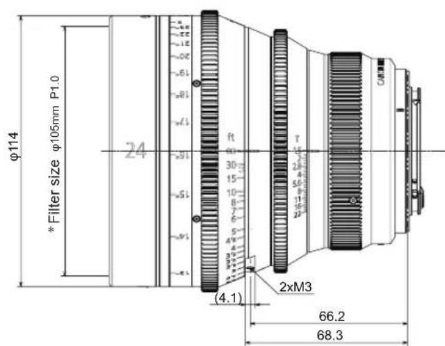
text_image
φ114 * Filter size φ105mm P1.0 24 ft 30 15 10 8 7 6 5 4" 4 3" 2" (4.1) 2xM3 66.2 68.3(Unit : mm)
text_image
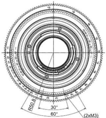
R50.8 30° 60° (2xM3)Spur gear specifications
| Focus drive gear Iris drive gear | |
| Number of teeth 146 126 | |
| Module 0.8 0.8 | |
| P.C. D. 116.8 mm 100.8 mm | |
| Angular rotation 300° 36° |
* CN-R14mm T3.1 L F cannot be used with a filter.
SPECIFICATIONS
| CN-R14mm T3.1 L F CN-R20mm T1.5 L F | ||||||
| Lens Mount RF RF | ||||||
| Focal Length 14mm 20mm | ||||||
| Maximum Relative Aperture(Tno) 1 : 3.1 1 : 1.5 | ||||||
| Iris Blade 11 11 | ||||||
| Image Circle φ43.3mm φ43.3mm | ||||||
| Aspect Ratio | 1.5 : 1 1.78 | 1 1.9 : 1 1.5 : 1 | 1.78 : 1 1.9 : 1 | |||
| Dimensions (H x V) | 36 x 24mm 24 | 6 x 13.8mm 26.2 | x 13.8mm 36 x 24 | mm 24.6 x 13.8mm | 26.2 x 13.8mm | |
| Angle of View (H / V) | 104.3° / 81.2° 8 | 2.6° / 52.5° 86.2° | / 52.5° 84.0° / 61 | 9° 63.2° / 38 | 1° 66.4° / 38.1° | |
| Minimum Object Distance(M.O.D.) [from the image sensor] | 0.2m (8") | 0.3m (12") | ||||
| Object Dimensions at M.O.D. (H x V) | 24.8 x 16.5cm | 16.9 x 9.5cm | 18.0 x 9.5cm | 33.8 x 22.5cm | 23.1 x 13.0cm | 24.6 x 13.0cm |
| Front Diameter | φ114mm | φ114mm | ||||
| Thread for filters | —* | φ105mm P1.0 | ||||
| Size (W x H x L) | Approx. 118.4 x 118.4 x 118.0mm | Approx. 118.4 x 118.4 x 125.5mm | ||||
| Weight | Approx. 1.3kg | Approx. 1.4kg | ||||
- A variety of professional camera accessories compatible with the 15 mm and 19 mm rod system can be used with this lens.
- Lenses compatible with Full-frame, Super 35mm, APS-H and APS-C Sensor cameras. When mounted on a camera with a different image size, the angle of view changes.
* CN-R14mm T3.1 LF cannot be used with a filter.
| CN-R24mm T1.5 L F CN-R35mm T1.5 L F | ||||||
| Lens Mount RF RF | ||||||
| Focal Length 24mm 35mm | ||||||
| Maximum Relative Aperture(Tno) 1 : 1.5 1 : 1.5 | ||||||
| Iris Blade 11 11 | ||||||
| Image Circle φ43.3mm φ43.3mm | ||||||
| Aspect Ratio | 1.5 : 1 1.78 | 1 1.9 : 1 1.5 : 1 | 1.78 : 1 1.9 : 1 | |||
| Dimensions (H x V) | 36 x 24mm 24 | 6 x 13.8mm 26.2 | x 13.8mm 36 x 24 | mm 24.6 x 13.8mm | 26.2 x 13.8mm | |
| Angle of View (H / V) | 73.7° / 53.1° | 54.3° / 32.1° | 57.3° / 32.1° | 54.4° / 37.8° | 38.7° / 22.3° | 41.0° / 22.3° |
| Minimum Object Distance(M.O.D.) [from the image sensor] | 0.3m (12") | 0.3m (12") | ||||
| Object Dimensions at M.O.D. (H x V) | 28.8 x 19.2cm | 19.7 x 11.0cm | 21.0 x 11.0cm | 20.1 x 13.4cm | 13.7 x 7.7cm | 14.6 x 7.7cm |
| Front Diameter | φ114mm | φ114mm | ||||
| Thread for filters | φ105mm P1.0 | φ105mm P1.0 | ||||
| Size (W x H x L) | Approx. 118.4 x 118.4 x 125.5mm | Approx. 118.4 x 118.4 x 125.5mm | ||||
| Weight | Approx. 1.3kg | Approx. 1.3kg | ||||
- A variety of professional camera accessories compatible with the 15 mm and 19 mm rod system can be used with this lens.
- Lenses compatible with Full-frame, Super 35mm, APS-H and APS-C Sensor cameras. When mounted on a camera with a different image size, the angle of view changes.
| CN-R50mm T1.3 L F CN-R85mm T1.3 L F | ||||||
| Lens Mount RF RF | ||||||
| Focal Length 50mm 85mm | ||||||
| Maximum Relative Aperture(Tno) 1 : 1.3 1 : 1.3 | ||||||
| Iris Blade 11 11 | ||||||
| Image Circle φ43.3mm φ43.3mm | ||||||
| Aspect Ratio | 1.5 : 1 1.78 | 1 1.9 : 1 1.5 : 1 | 1.78 : 1 1.9 : 1 | |||
| Dimensions (H x V) | 36 x 24mm 24 | 6 x 13.8mm 26.2 | x 13.8mm 36 x 24 | mm 24.6 x 13.8mm | 26.2 x 13.8mm | |
| Angle of View (H / V) | 39.6° / 27.0° | 27.6° / 15.7° | 29.4° / 15.7° | 23.9° / 16.1° | 16.5° / 9.3° | 17.5° / 9.3° |
| Minimum Object Distance(M.O.D.) [from the image sensor] | 0.45m (18") | 0.95m (3'2") | ||||
| Object Dimensions at M.O.D. (H x V) | 24.9 x 16.6cm | 17.0 x 9.5cm | 18.1 x 9.5cm | 34.3 x 22.9cm | 23.4 x 13.1cm | 25.0 x 13.1cm |
| Front Diameter | φ114mm | φ114mm | ||||
| Thread for filters | φ105mm P1.0 | φ105mm P1.0 | ||||
| Size (W x H x L) | Approx. 118.4 x 118.4 x 125.5mm | Approx. 118.4 x 118.4 x 125.5mm | ||||
| Weight | Approx. 1.2kg | Approx. 1.5kg | ||||
- A variety of professional camera accessories compatible with the 15 mm and 19 mm rod system can be used with this lens.
- Lenses compatible with Full-frame, Super 35mm, APS-H and APS-C Sensor cameras. When mounted on a camera with a different image size, the angle of view changes.
| CN-R135mm T2.2 L F | |||
| Lens Mount RF | |||
| Focal Length | 135mm | ||
| Maximum Relative Aperture(Tno) 1 : 2.2 | |||
| Iris Blade 11 | |||
| Image Circle φ43.3mm | |||
| Aspect Ratio | 1.5 : 1 1.78 | 1 1.9 : 1 | |
| Dimensions (H x V) | 36 x 24mm 24 | 6 x 13.8mm 26.2 | x 13.8mm |
| Angle of View (H / V) | 15.2° / 10.2° | 10.4° / 5.9° | 11.1° / 5.9° |
| Minimum Object Distance(M.O.D.) [from the image sensor] | 1m (3'4") | ||
| Object Dimensions at M.O.D. (H x V) | 21.1 x 14.1cm | 14.4 x 8.1cm | 15.4 x 8.1cm |
| Front Diameter | φ114mm | ||
| Thread for filters | φ105mm P1.0 | ||
| Size (W x H x L) | Approx. 118.4 x 118.4 x 139.6mm | ||
| Weight | Approx. 1.5kg | ||
- A variety of professional camera accessories compatible with the 15 mm and 19 mm rod system can be used with this lens.
- Lenses compatible with Full-frame, Super 35mm, APS-H and APS-C Sensor cameras. When mounted on a camera with a different image size, the angle of view changes.
Reference Information
This lens is a full manual lens for shooting movies.
- RF Cinema lenses were developed primarily for movie production, and have a color balance typical for movies. When using this lens together with EF/RF lenses which are basically used to shoot still images, adjust the color balance (redo the white balance etc.) as necessary.
- In general, the depth of field becomes shallow and the focusing range becomes extremely narrow near the widest aperture and when shooting a subject at close range. In addition, this tendency increases for lenses with longer focal lengths. When shooting images, carefully check the focusing condition using the zoom mode of the finder or other means, and shoot a sufficient number of test images before performing focus operations.
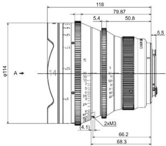
EXTERNAL VIEW
CN-R14mm T3.1 L F E20
CN-R20mm T1.5 L F..... E22
CN-R24mm T1.5 L F....E24
CN-R35mm T1.5 L F..... E26
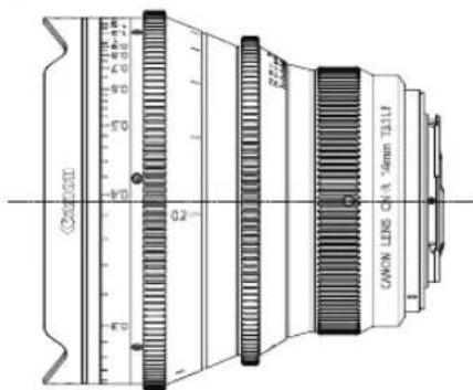
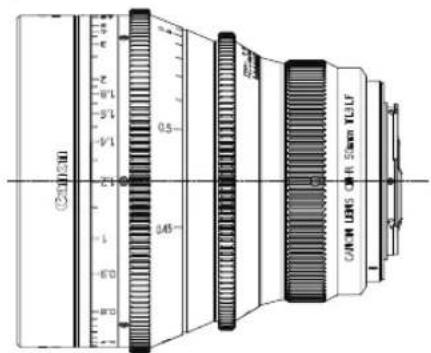
CN-R50mm T1.3 L F..... E28
CN-R85mm T1.3 L F..... E30
CN-R135mm T2.2 L F....E32
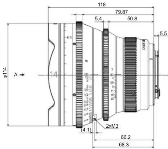
CN-R14mm T3.1 L F
Feet
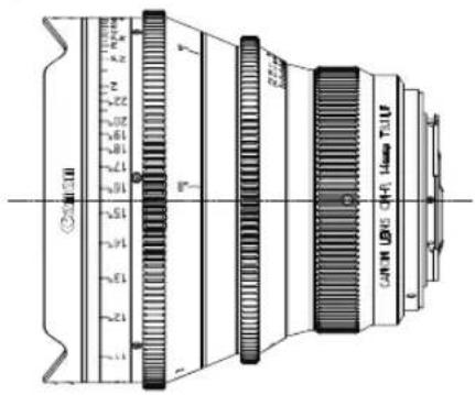
text_image
2000 1.5 2.5 3.5 4.5 5.5 6.5 7.5 8.5 9.5 10.5 11.5 12.5 13.5 14.5 15.5 16.5 17.5 18.5 19.5 20.5 21.5 22.5 23.5 24.5 25.5 26.5 27.5 28.5 29.5 30.5 31.5 32.5 33.5 34.5 35.5 36.5 37.5 38.5 39.5 40.5 41.5 42.5 43.5 44.5 45.5 46.5 47.5 48.5 49.5 50.5 51.5 52.5 53.5 54.5 55.5 56.5 57.5 58.5 59.5 60.5 61.5 62.5 63.5 64.5 65.5 66.5 67.5 68.5 69.5 70.5 71.5 72.5 73.5 74.5 75.5 76.5 77.5 78.5 79.5 80.5 81.5 82.5 83.5 84.5 85.5 86.5 87.5 88.5 89.5 90.5 91.5 92.5 93.5 94.5 95.5 96.5 97.5 98.5 99.5 100.0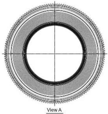
natural_image
Cross-sectional diagram of a mechanical gear or cam mechanism with concentric rings and central bore (no text or symbols)(Unit : mm)
text_image
φ114 A → 118 79.87 5.4 50.8 5.5 2xM3 (4.1) 66.2 68.3
text_image
R50.8 30° 60° (2xM3)E20
CN-R14mm T3.1 L F
Meter
text_image
ON/OFF 0.2 0.4 0.6 0.8 1.0 1.2 1.4 1.6 1.8 2.0 2.2 2.4 2.6 2.8 3.0 3.2 3.4 3.6 3.8 4.0 4.2 4.4 4.6 4.8 5.0 5.2 5.4 5.6 5.8 6.0 6.2 6.4 6.6 6.8 7.0 7.2 7.4 7.6 7.8 8.0 8.2 8.4 8.6 8.8 9.0 9.2 9.4 9.6 9.8 10.0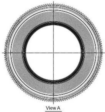
natural_image
Cross-sectional diagram of a mechanical gear or cam mechanism with concentric rings and central bore (no text or symbols)(Unit : mm)
text_image
φ114 A → 118 79.87 5.4 50.8 5.5 66.2 68.3 2xM3 (4.1) m 1 2 3 4 5 6 7 8 9 10 11 12 13 14 15 16 17 18 19 20 21 22 23 24 25 26 27 28 29 30 31 32 33 34 35 36 37 38 39 40 41 42 43 44 45 46 47 48 49 50 51 52 53 54 55 56 57 58 59 60 61 62 63 64 65 66 67 68.3
text_image
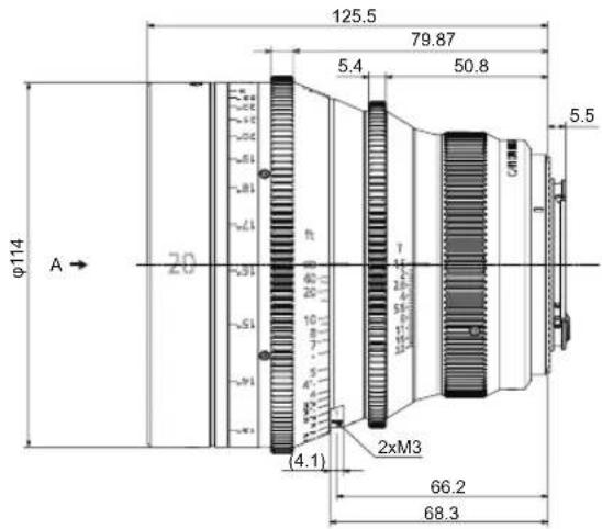
R50.8 30° 60° (2xM3)CN-R20mm T1.5 L F
Feet

text_image
Ø20mm 12" 13" 14" 20" LTR GAIN LTR5 OF R.2mm TSLF
natural_image
Cross-sectional diagram of a circular mechanical component with concentric rings and centerlines, labeled 'View A' at bottom (no other text or symbols)(Unit : mm)
text_image
φ114 A → 20 125.5 79.87 5.4 50.8 5.5 (4.1) 2xM3 66.2 68.3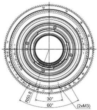
text_image
R50.8 30° 60° (2xM3)E22
CN-R20mm T1.5 L F
Meter

text_image
C200/10 0.3 CATN 105 CH-4 2mm TULF
natural_image
Cross-sectional diagram of a mechanical ring or gear assembly with concentric rings and central axis (no text or symbols)(Unit : mm)

text_image
φ114 A → 20 50 70 125.5 79.87 5.4 50.8 5.5 2xM3 (4.1) 66.2 68.3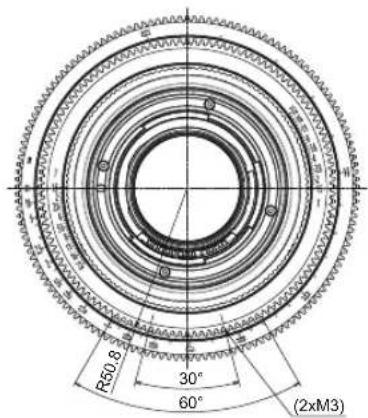
text_image
R50.8 30° 60° (2xM3)CN-R24mm T1.5 L F
Feet

text_image
C2015/19 1.2 2.7 3.4 4.8 6.3 7.8 9.2 10.7 12.2 13.7 15.2 16.7 18.2 19.7 21.2 22.7 24.2 25.7 27.2 28.7 30.2 31.7 33.2 34.7 36.2 37.7 39.2 40.7 42.2 43.7 45.2 46.7 48.2 49.7 51.2 52.7 54.2 55.7 57.2 58.7 59.2 60.7 62.2 63.2 64.2 65.2 66.2 67.2 68.2 69.2 70.2 71.2 72.2 73.2 74.2 75.2 76.2 77.2 78.2 79.2 80.2 81.2 82.2 83.2 84.2 85.2 86.2 87.2 88.2 89.2 90.2 91.2 92.2 93.2 94.2 95.2 96.2 97.2 98.2 99.2 100.2
natural_image
Cross-sectional diagram of a mechanical gear or cam mechanism with concentric rings and central bore (no text or symbols)(Unit : mm)

text_image
φ114 A → 24 125.5 79.87 5.4 50.8 5.5 2xM3 (4.1) 66.2 68.3
text_image
R50.8 30° 60° (2xM3)E24
CN-R24mm T1.5 L F
Meter

text_image
(CAN1022) 0.3 0.5 0.7 0.9 1.1 1.3 1.5 1.7 1.9 2.1 2.3 2.5 2.7 2.9 3.1 3.3 3.5 3.7 3.9 4.1 4.3 4.5 4.7 4.9 5.1 5.3 5.5 5.7 5.9 6.1 6.3 6.5 6.7 6.9 7.1 7.3 7.5 7.7 7.9 8.1 8.3 8.5 8.7 8.9 9.1 9.3 9.5 9.7 9.9 10.1
natural_image
Cross-sectional diagram of a mechanical gear or cam mechanism with concentric rings and central bore (no text or symbols)(Unit : mm)
text_image
φ114 A → 24 50 125.5 79.87 5.4 50.8 5.5 m 10 5 3 2.5 1.5 1.5 1.3 (4.1) 2xM3 66.2 68.3
text_image
R50.8 30° 60° (2xM3)CN-R35mm T1.5 L F
Feet
text_image
C2005H 13° 12° 11° 10° 9° 8° 7° 6° 5° 4° 3° 2° 1° 0.5 0.4 0.3 0.2 0.1 0.05 0.04 0.03 0.02 0.01 0.005 0.004 0.003 0.002 0.001 0.0005 0.0004 0.0003 0.0002 0.0001 0.00005 0.00004 0.00003 0.00002 0.00001 0.000005 0.000004 0.000003 0.000002 0.000001 0.0000005 - 35mm T25V
natural_image
Circular mechanical component with concentric rings and central hole, labeled 'View A' at bottom (no other text or symbols)(Unit : mm)
text_image
φ114 A → 125.5 79.87 5.4 50.8 5.5 2xM3 (4.1) 66.2 68.3
text_image
R50.8 30° 60° (2xM3)CN-R35mm T1.5 L F
Meter

text_image
CANAGON 0.3" CANON LENS CFA 35mm TULF
natural_image
Circular mechanical component with concentric rings and central hole, labeled 'View A' at bottom (no other text or symbols)(Unit : mm)
text_image
φ114 A → 125.5 79.87 5.4 50.8 5.5 66.2 68.3 (4.1) 2xM3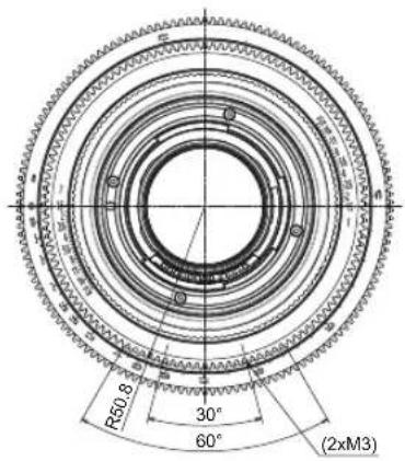
text_image
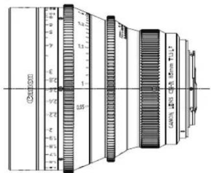
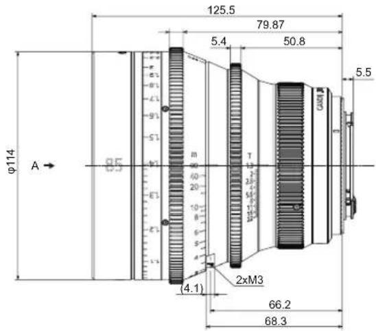
R50.8 30° 60° (2xM3)CN-R50mm T1.3 L F
Feet

natural_image
Cross-sectional diagram of a mechanical component with concentric rings and central bore (no text or symbols)(Unit : mm)

text_image
φ114 A → 125.5 79.87 5.4 50.8 5.5 66.2 68.3 (4.1) 2xM3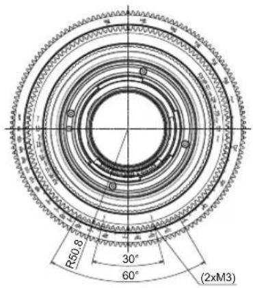
text_image
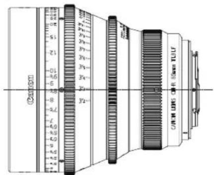
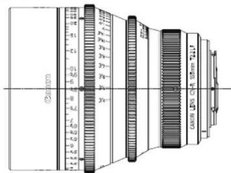
R50.8 30° 60° (2xM3)CN-R50mm T1.3 L F
Meter
text_image
200/150 0.5 245 GAIN LENS OF 5mm TGLF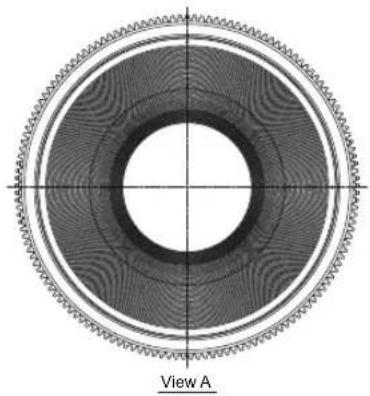
natural_image
Cross-sectional diagram of a mechanical component with concentric rings and central axis (no text or symbols)(Unit : mm)

text_image
φ114 A → 125.5 79.87 5.4 50.8 5.5 m 20 10 5 4 3 2 (4.1) 2xM3 66.2 68.3
text_image
R50.8 30° 60° (2xM3)CN-R85mm T1.3 L F
Feet
text_image
Cavon CAVM LENS OF R. 52mm TULF
natural_image
Cross-sectional diagram of a mechanical ring or gear assembly with concentric rings and central axis lines (no text or symbols)(Unit : mm)

text_image
φ114 A → 125.5 79.87 5.4 50.8 5.5 (4.1) 2xM3 66.2 68.3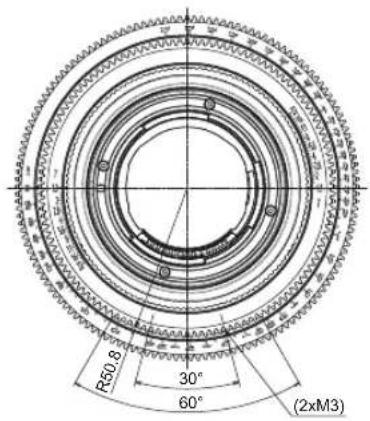
text_image
R50.8 30° 60° (2xM3)E30
CN-R85mm T1.3 L F
Meter
text_image
Chamom 1.0 2.0 3.0 4.0 5.0 6.0 7.0 8.0 9.0 10.0 11.0 12.0 13.0 14.0 15.0 16.0 17.0 18.0 19.0 20.0 21.0 22.0 23.0 24.0 25.0 26.0 27.0 28.0 29.0 30.0 31.0 32.0 33.0 34.0 35.0 36.0 37.0 38.0 39.0 40.0 41.0 42.0 43.0 44.0 45.0 46.0 47.0 48.0 49.0 50.0 51.0 52.0 53.0 54.0 55.0 56.0 57.0 58.0 59.0 60.0 61.0 62.0 63.0 64.0 65.0 66.0 67.0 68.0 69.0 70.0 71.0 72.0 73.0 74.0 75.0 76.0 77.0 78.0 79.0 80.0 81.0 82.0 83.0 84.0 85.0 86.0 87.0 88.0 89.0 90.0 91.0 92.0 93.0 94.0 95.0 96.0 97.0 98.0 99.0 100.0
natural_image
Cross-sectional diagram of a mechanical ring or gear assembly with concentric rings and central axis (no text or symbols)(Unit : mm)
text_image
φ114 A → 125.5 79.87 5.4 50.8 5.5 2xM3 (4.1) 66.2 68.3
text_image
R50.8 30° 60° (2xM3)CN-R135mm T2.2 L F
Feet
text_image
24mm CANOIL LENS CV-A 50mm 724.1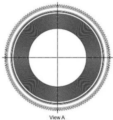
natural_image
Cross-sectional diagram of a mechanical ring or gear assembly with concentric rings and central axis (no text or symbols)(Unit : mm)
text_image
φ114 A 139.6 79.87 5.4 50.8 5.5 2xM3 (4.1) 66.2 68.3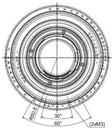
text_image
R50.8 30° 60° (2xM3)E32
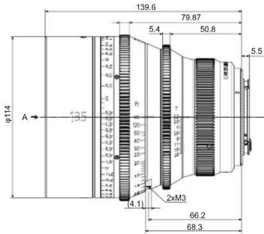
CN-R135mm T2.2 L F
Meter

text_image
(240mm)
natural_image
Cross-sectional diagram of a mechanical ring or gear assembly with concentric rings and central axis (no text or symbols)(Unit : mm)

text_image
φ114 A → 139.6 79.87 5.4 50.8 5.5 2xM3 (4.1) 66.2 68.3
text_image
R50.8 30° 60° (2xM3)Canon
CANON INC.
30-2, Shimomaruko 3-chome, Ohta-ku, Tokyo 146-8501, Japan
BT1-D033-A-ENG ©2023.07 CANON INC.