
ALF-20X-HD-TC - Security Camera Alfatron - Free user manual and instructions
Find the device manual for free ALF-20X-HD-TC Alfatron in PDF.

| Product Type | Security PTZ Tracking Camera |
| Brand & Model | Alfatron ALF-20X-HD-TC |
| Image Sensor | 1/2.8-inch High-Quality CMOS, 2.07 MP (16:9) |
| Optical Zoom | 20X (f=4.7 mm ~ 94 mm) |
| Digital Zoom | 10X |
| Horizontal Rotation | -170° to +170° |
| Vertical Rotation | -30° to +90° |
| Video Output | HDMI, USB3.0, SDI (depending on model), up to 1080p60 |
| Video Compression | H.265, H.264 |
| Audio Input | Dual 3.5 mm linear, supports AAC, MP3, G.711A |
| Network | 10/100BASE-TX Ethernet, optional 5G WiFi |
| Supported Protocols | ONVIF, GB/T28181, RTSP, RTMP, VISCA, PELCO-D/P |
| Power Supply | DC12V ±10%, 1.5A max (18W max) |
| Dimensions (WxHxD) | 254 mm x 144 mm x 174 mm |
| Weight | Approx. 1.50 kg |
| Operating Temperature | -10°C to +50°C |
| Storage Temperature | -10°C to +60°C |
| Maintenance | Wipe lens with soft dry cloth; use neutral cleaner if needed |
| Safety Warnings | Do not disassemble; use only specified power adapter; avoid corrosive liquids |
| Warranty | 7-year limited warranty on materials and workmanship |
| Repairability | No user-serviceable parts; contact authorized service for repairs |
| Accessories Included | Power adapter, RS232 control cable, remote control, manual, warranty card |
Frequently Asked Questions - ALF-20X-HD-TC Alfatron
User questions about ALF-20X-HD-TC Alfatron
0 question about this device. Answer the ones you know or ask your own.
Ask a new question about this device
Download the instructions for your Security Camera in PDF format for free! Find your manual ALF-20X-HD-TC - Alfatron and take your electronic device back in hand. On this page are published all the documents necessary for the use of your device. ALF-20X-HD-TC by Alfatron.
USER MANUAL ALF-20X-HD-TC Alfatron
natural_image
Exterior view of a modern automated camera with a circular lens and a labeled 'ALFATRON' button (no other text or symbols visible)FCC Statement
CE F© EAC CAN ICES-3 (B)/NMB-3(B)
NOTE: This equipment has been tested and found to comply with the limits for a Class B digital device, pursuant to Part 15 of the FCC Rules. These limits are designed to provide reasonable protection against harmful interference in a residential installation. This equipment generates, uses and can radiate radio frequency energy and, if not installed and used in accordance with the instructions, may cause harmful interference to radio communications. However, there is no guarantee that interference will not occur in a particular installation. If this equipment does cause harmful interference to radio or television reception, which can be determined by turning the equipment off and on, the user is encouraged to try to correct the interference by one or more of the following measures:
---Reorient or relocate the receiving antenna.
---Increase the separation between the equipment and receiver.
---Connect the equipment into an outlet on a circuit different from that to which the receiver is connected.
---Consult the dealer or an experienced radio/TV technician for help.
WARNING: Changes or modifications not expressly approved by the party responsible for compliance could void the user's authority to operate the equipment.
Radiation Exposure
This equipment complies with FCC radiation exposure limits set forth for an uncontrolled environment.
This device complies with Industry Canada licence-exempt RSS standard(s). Operation is subject to the following two conditions:
(1) this device may not cause interference, and
(2) this device must accept any interference, including interference that may cause undesired operation of the device.
Radiation Exposure:
This equipment complies with IC radiation exposure limits set forth for an uncontrolled environment.
Do not dispose of this product with the normal household waste at the end of its life cycle. Return it to a collection point for the recycling of electrical and electronic devices. This is indicated by the symbol on the product, user manual or packaging. The materials are reusable according to their markings. By reusing, recycling or other forms of utilisation of old devices you make an important contribution to the protection of our environment. Please contact your local authorities for details about collection points.
Preface
This manual describes the functions, installation and operation principles and methods of the product in detail. Before installing and using this product, please read it carefully.
1. Safety precautions
- During transportation, storage, installation, and use, it is necessary to prevent heavy pressure, severe vibration, and immersion to avoid damage to the product.
- The product shell is made of organic material. Ensure product does not encounter corrosive liquid, gas, or solid substances.
- Do not let the product get wet or rained on. Do not use it beyond the limit of temperature and humidity.
- When cleaning the lens, please use a soft dry cloth to wipe. When there is a lot of dust, please use a neutral cleaner and wipe gently.
- Do not use a strong or corrosive detergent to avoid scratching the lens and affecting the image.
- This product has no parts that users can repair by themselves, and the damage caused by users 'self-disassembly does not fall within the scope of warranty.
2. Electrical safety
- The installation and use of products must strictly comply with the national and local electrical safety standards.
- Do not use power adapters beyond the specifications of the power supply, otherwise the equipment components will burn out and will not work properly.
- In the process of using the product, we should keep enough distance from the high-power equipment, and do a good job of lightning protection, surge protection and other protective measures when necessary.
- When the product is not in use, please disconnect the power switch and disconnect the power adapter from the power socket.
- The product uses a DC 12V power supply, and the polarity of the power plug is as shown in the picture.
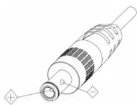
natural_image
Technical line drawing of a mechanical component with no visible text or symbols3. Installation Safety
- Do not rotate the cylinder of the product by hand, otherwise it will destroy the rotating shaft of the structure.
- Installation and placement of equipment should be horizontal and stable, and the product should not be tilted, otherwise the picture may be skewed.
- Installation ensures that there are no obstacles in the rotating range of the platform to prevent damage to the rotating shaft of the structure.
- Do not turn on the power until all installation work is completed.
4. Magnetic Interference
- The electromagnetic field at a specific frequency may affect the local image. The product is Class A product. Radio interference may occur in the home environment, and users need to take appropriate measures.


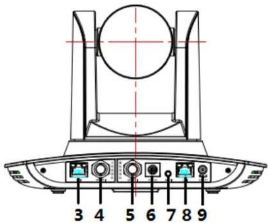
natural_image
Line drawing of an electronic device with two labeled connectors (1 and 2), no text or symbols present.If it is needed to extend the power line of the camera, extend it from terminal 1 (220V/110V) rather than terminal 2 (DC12V), otherwise, it will prevent the device from functioning!
Table of Contents
- System overview ....4
1.1 System introduction ....4
1.2 Product advantages....4
1.3 Product features....5
- Port introduction - ALF-XX-HD-TC....6
2.1 Port introduction – ALF-XX-SD-TC ....7
-
Dimensions....9
-
System connection....10
4.1 Installation layout....10
4.2 System wiring....11
- Configuration tools....12
5.1 Set IP address of the tracking machine .... 12
5.2 Configure tracking parameters....13
5.3 Network update ....19
- Description of recording and broadcasting host 20
6.1 Auto tracking control....20
6.2 Action code docking....21
- Description of remote control....23
7.1.Description of keys....23
7.2 Use remote control....24
8 Set menu 27
8.1 Main menu....27
8.2 System parameter settings....27
8.3 Camera parameter settings....28
8.4 P/T/Z 32
8.5 Video format.... 33
8.6 Version....33
8.7 Restore default....34
-
Technical parameters ....34
-
VISCA protocol command list....36
-
Pelco-D protocol command list ....45
-
Pelco-P protocol command list....46
13 Maintenance and troubleshooting ....48
13.1 Maintenance ....48
13.2 Troubleshooting 48
After-sales Service....50
Warranty 51
1. System overview
1.1 System introduction
The ALF-XX-HD-TC / ALF-XX-SD-TC is a dedicated smart camera solution leading in the international education information industry.
The tracking camera features a built-in high-speed processor and advanced image processing and analytical algorithm, which allows it to track and detect teachers, students and blackboard-writing accurately and quickly. It fully satisfies all scenario demands by recorded broadcasting of teaching and remote interactive teaching.
The tracking camera adopts an advanced ISP processing technique and algorithm, producing vivid images which feature balanced brightness, distinct layering, high definition and colour reducibility.
The ALF-XX-HD-TC range are characterized by improved function, high performance, reliable operation, simple use and easy maintenance.
1.2 Product advantages
● Full-scene solution: Different product combinations satisfy different scenario demands.
- Networked control interface: Control information of all products will be transmitted via a network, and it is suitable for product layout for all scenarios.
- Recognition algorithm unrelated to the location: Status detection and recognition of teachers and students adopt a unique smart partitioning algorithm to ensure that the result of detection and recognition is unrelated to location.
Ease of installation: Supports both standing installation and upside-down installation.
- All-in-one design: The built-in panoramic lens allows the perfect combination of panoramic lens and tracking camera.
- Sophisticated tracking algorithm: It applies sophisticated human detection, locking and tracking image processing and analytical algorithm (smart image recognition library, scene adaptive algorithm), and achieves stable, fast and accurate target tracking.
- High immunity from interference: More diversified and flexible recognition shield settings ensure that once the tracking target is locked, it will not be affected by another moving object or projector.
- Stable tracking: Movement sensitivity is adjustable. When tracking a slight movement of target or hand movement, it will not cause the wrong operation of the camera.
- Self-adaptive image: The tracking camera zooms depending on the distance to target so that the visual image maintains proper size and scale.
- High environmental suitability: Tracking result will not be affected by classroom size, shape or seat arrangement.
- Super wide dynamic exposure: Solves the issue that tracking object dims in strong light such as a projector.
1.3 Product features
● Full HD image: With a 1/2.8-inch-high quality image sensor, the maximum resolution ratio is 1920x1080.
- Multiple optical zoom lens: 12X and 20X optical zoom lens are available. The lens features a 72.5irc distortionless wide viewing angle.
- Advanced focusing technique: The advanced automatic focusing algorithm allows automatic focusing to be done quickly, accurately and steadily.
- Low noise high signal to noise ratio: Low noise CMOS ensures super high signal to noise ratio of video taken by the camera. With advanced 2D and 3D noise reduction technology, noise is reduced, and image resolution is guaranteed.
● Audio input port: It supports 16000, 32000, 44100, 48000 Hz sampling frequency and AAC, MP3 and G.711A audio coding.
- Super quiet mechanism: High precision stepping motor and precision motor-driven controller ensure the PTZ mechanism operates at low and stable speed without noise.
● Multiple video compression standards: It supports H.265 / H.264 video compression.
- Multiple networking protocols: It supports ONVIF, GB/T28181, RTSP, protocol and RTMP push mode.
- Sleep mode: It supports low-power consumption sleep / wake up mode. Power consumption in sleep mode is lower than 400mW.
- Multiple control protocol: Supports VISCA, PELCO-D, PELCO-P protocol, automatic recognition protocol and all command VISCA control protocol.
2. Port introduction – ALF-XX-HD-TC

- Close-up lens
- Panorama (Wide) lens
- USB3.0 output 1 (panorama lens output)
- HDMI output 1 (panorama lens output)
- LAN network port for panorama lens
- USB3.0 output 2 (close-up lens output)
- HDMI output 2 (close-up lens output)
- RS-232 control port
- Audio input port
- LAN network port for close-up lens
- Power supply port (DC12V)
2.1 Port introduction – ALF-XX-SD-TC
- Close-up lens
- Panorama lens
- LAN network port for panorama lens
- SDI output 1 (panorama lens output)
- SDI output 2 (close-up lens output)
- RS-232 control port
- Audio input port
- LAN network port for close-up lens
- Power supply port (DC12V)
Pin definition:
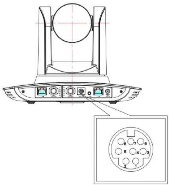
| No. | Port | Definition |
| 1 | DTR | Data Terminal Ready |
| 2 | DSR | Data Set Ready |
| 3 | TXD | Transmit Data |
| 4 | GND | Signal ground |
| 5 | RXD | Receive Data |
| 6 | GND | Signal ground |
| 7 | IR OUT | IR Commander Signal IR |
| 8 | NC | No Connection |
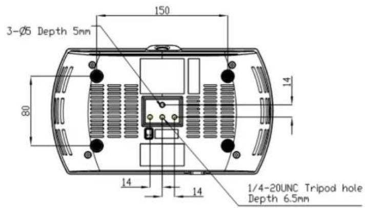
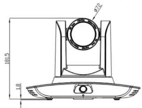
3. Dimensions
4. System connection
4.1 Installation layout
Space for blackboard-writing detection and camera installation
Space for installation of student-tracking camera, student status detection camera and student binocular camera

natural_image
Technical line drawing of a mechanical component with two views (top and side), no text or symbols present.Blackboard

Student area

natural_image
Three empty rectangular boxes arranged horizontally (no text or symbols)
natural_image
Three empty rectangular boxes arranged horizontally (no text or symbols)
natural_image
Three empty rectangular boxes arranged horizontally (no text or symbols)
natural_image
Three empty rectangular boxes arranged horizontally (no text or symbols)
natural_image
Technical line drawing of a mechanical component with cross-sectional and top views (no text or symbols)Space for installation of teacher tracking camera teacher status detection camera and teacher binocular camera
The tracking camera is installed about 1.8 - 2.5m from the ground (distance from the panoramic lens to the floor), 5 - 15m from the blackboard (when the distance is 5 - 9m, 4mm panoramic lens is recommended; when distance is 9 - 15m, 6mm panoramic lens is recommended). Teacher tracking camera should be installed near the central axis of the classroom as much as possible to get the best result of tracking camera shooting.
4.2 System wiring
The tracking camera provides a smart camera solution for the education information field. Different combinations of products meet the demand of customers' application scenarios.

flowchart
graph TD
    A["Teacher tracking camera, teacher status detection camera, teacher binocular camera"] --> B["SDI"]
    C["Student-tracking camera, student status detection camera, student binocular camera"] --> D["SDI"]
    B --> E["Computer"]
    D --> E
    E --> F["Laptop"]
    style A fill:#f9f,stroke:#333
    style C fill:#f9f,stroke:#333
    style B fill:#ccf,stroke:#333
    style D fill:#ccf,stroke:#333
    style E fill:#cfc,stroke:#333
If the recording and broadcasting host supports the LAN network control port, the network hub can be replaced by a LAN network switch.
5. Configuration tools
5.1 Set IP address of the tracking machine
Open Alfatron tracking software, click Settings -> IP address -> Search successively (refer to Figure 5.1-1 for details), the configuration interface will display all valid devices in the LAN, check the type of device to be configured and click Confirm. Note: The computer for operating the Alfatron tracking software tool should be in the same LAN with the camera to be configured.

Figure 5.1-1 Operation interface
5.2 Configure tracking parameters.
To configure, follow the below process:
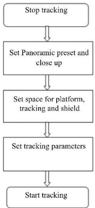
flowchart
graph TD
    A["Stop tracking"] --> B["Set Panoramic preset and close up"]
    B --> C["Set space for platform, tracking and shield"]
    C --> D["Set tracking parameters"]
    D --> E["Start tracking"]
The following is a depiction of the configuration for the above process:
The main interface of the configuration tool is shown in Figure 5.2-1.

Figure 5.2-1 Operation interface
1. Set the preset position for close up
The operation interface for setting preset position for close up is shown in Figure 5.2-2.
The framed area indicated by the arrow has the PTZ control buttons. By controlling the Pan / Tilt position and Zoom value, it will adjust the camera angle and position to the desired preset position. Settings of panoramic preset position and platform preset position are as follows:
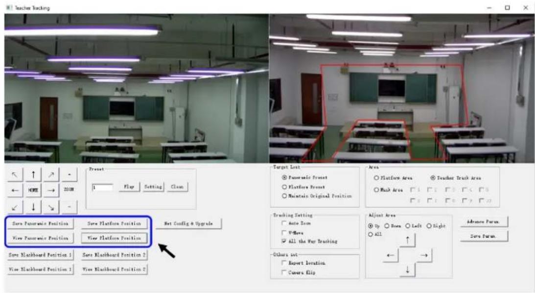
Figure 5.2-2 Operation interface
Platform preset: Control the tracking camera (close up camera) to create a platform area and get the desired visual result in-camera image, then click and save Platform preset. During normal tracking, the size of the persons image in the picture uses a Platform preset as a reference. When the tracking target disappears, it can select a close-up lens to go back to the Platform preset.
Panoramic preset: Control tracking camera to allow it to have a panoramic view of the classroom (or any position). When the tracking target disappears, it can select the close-up lens to go back to the panoramic position.
2. Set panoramic lens area
Platform area: This is the area that is tracked once the close-up lens starts tracking. There is a blackboard within the platform area generally to ensure that when the teacher is on the platform their upper body is displayed within the set area, and it will not exceed the lower margin of the platform area when students in the first row sit down. See Figure 5.2-3.
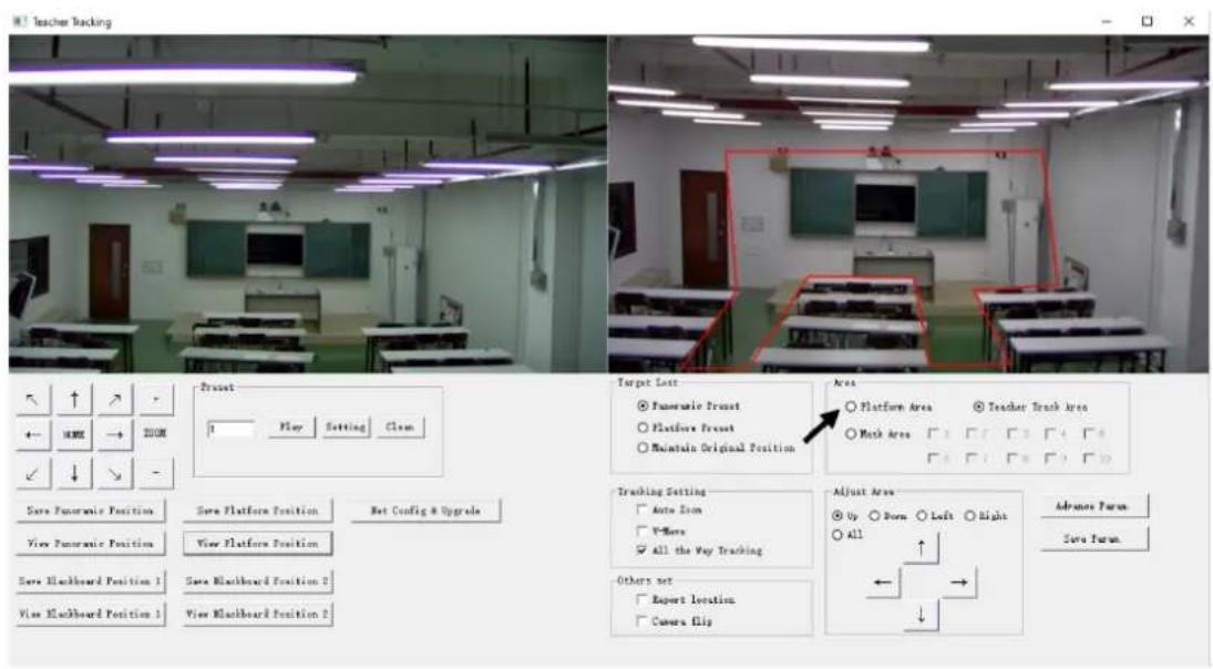
Figure 5.2-3 Operation interface
Tracking area: Tracking area means the scope of area tracking the teacher. When the tracking target goes out of the tracking area, it will be considered as tracking target lost. The tracking area can be set into a polygon shape according to certain environmental conditions or set student area outside of tracking area. See Figure 5.2-4:
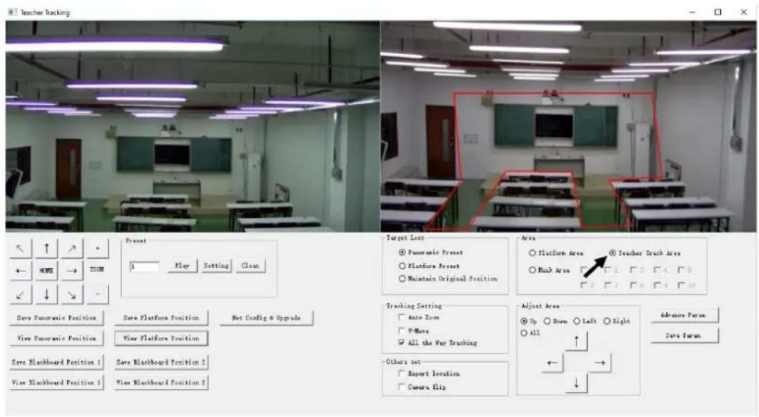
Figure 5.2-4 Operation interface
Mask area: The mask area is an area that may impact the effectiveness of target tracking, these are places that may have dynamic changes such as monitors, projector, doors, and windows. See Figure 5.2-5:
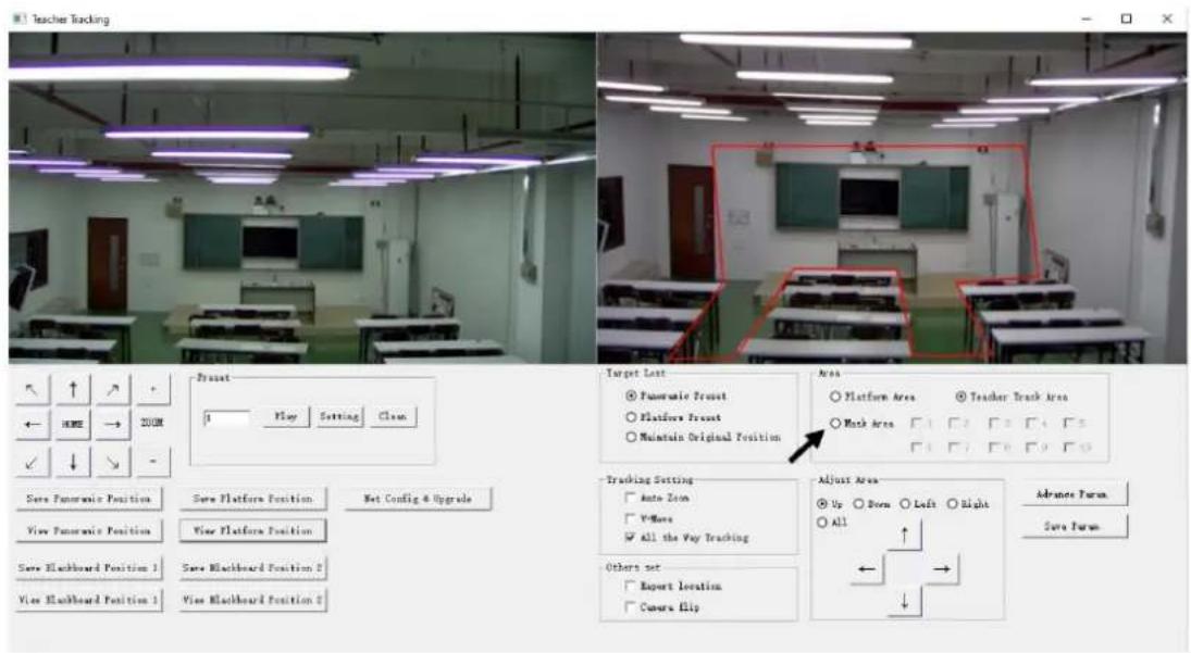
Figure 5.2-5 Operation interface
3. Set tracking parameters
Target lost: When the target is lost, the close-up lens will return to a designated preset position. This preset position can be the Panoramic Preset, Platform Preset or Maintain Original Position.

Figure 5.2-6 Operation interface
Tracking settings:
Auto-zoom: In open mode (checked), during tracking, the camera will zoom automatically according to target distance; in off mode (unchecked), during tracking, zoom remains to the value set during platform preset.
V-move: In open mode (checked) and during tracking, the camera will adjust its angle of elevation according to the height of the tracking target; in off mode (unchecked) and during tracking, the angle of elevation remains to the value set during platform preset. If a teacher does not step down from the platform in class, we suggest turning off the auto-zoom and v-move.
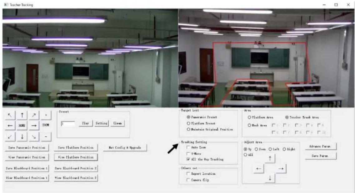
Figure 5.2-7 Operation interface
Advanced parameters:
Action sensitivity: In tracking mode, it is the action range required to trigger the tracking camera when the tracking target changes from a stationary state to a motion state. The higher the action sensitivity, the smaller the movement of the tracking target that will trigger the camera's tracking motion.
H-speed: It means the speed of the camera for horizontal tracking.
V-speed: It means the speed of the camera for vertical tracking.
Zoom range: The bigger the range, the higher zoom extent required for the camera when the tracking target steps down from the platform.
Lost timeout: This means the time required (5s by default) for the camera to perform the target lost action when the target is lost (options: return to panorama preset, platform preset, or remain original position).
Down platform sensitivity: This is used for determining if a teacher steps down from the platform. The lower the sensitivity, the longer the teacher's distance to the blackboard is required to trigger the down platform action.

Figure 5.2-5 Operation interface
For settings of action code, refer to "6.2 Description of connecting recording and broadcasting host".
After setting, click Save Parameter. This allows entering the advance parameter settings column to change configuration value to obtain the best result subject to specific scenes and requirements.
5.3 Network update
When updating the camera firmware, please use the Alfatron tracking software application. Click Configuration -> Network configuration & update, to enter update interface, as shown below:

Figure 5.2-8 Operation interface
When upgrading, note whether the camera to be upgraded is the close-up camera or panorama camera, then click Select file -> upgrade, the following interface appears:

After upgrading is completed, the camera will perform self-inspection.
Note: After grading, you can restore factory settings by combination key [*] [#] [6] on the remote control or by remote control menu.
6. Description of recording and broadcasting host
6.1 Auto tracking control
The recording and broadcasting host sends commands via the LAN network port or network hub RS232 serial port and controls automatic tracking motion of teacher tracking camera. In auto-tracking mode, it does not allow control of the camera rotation or zoom by Alfatron tracking software tool or remote control; in stop auto-tracking mode, it allows control of the camera rotation or zoom by Alfatron tracking software tool or remote control.
1. Network receiving address
Address for teacher tracking camera to receive commands can be searched in Alfatron tracking software, click Setting -> IP address -> search, as follows:
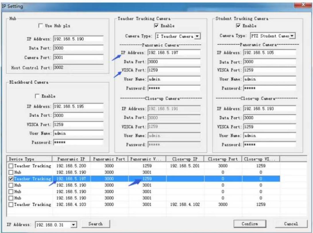
Figure 6.1-1 Operation interface
2. Command
| Type | Command |
| Start teacher tracking 0x810x0A 0x08 0x01 0x020xFF | |
| Stop teacher tracking 0x81 0x0A 0x08 0x01 0x03 0xFF | |
6.2 Action code docking
The tracking status of the teacher tracking camera will give feedback to the recording and broadcasting host via the network (UDP transmission mode) or network hub (RS232 serial port) in the form of an action code.
1. Configure recording and broadcasting host address
If the recording and the broadcasting host use LAN to receive the activation code, then it needs to configure the host address via the Alfatron tracking software tool. Click Configuration -> Network configuration & update, as shown below:
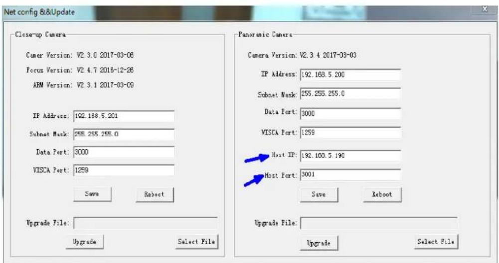
Figure 6.2-1 Operation interface
2. Configure action code
Edit action code as needed via the Alfatron tracking software tool. Click Configuration -> advance parameters.
After modification, click Confirm -> save parameters, as shown below:

Figure 6.2-2 Operation interface
7. Description of remote control
7.1. Description of keys
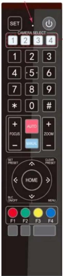
1. Standby key
Long press standby key for 3s, the camera enters standby mode, long press this key again for 3s, the camera will perform self-inspection and return to the HOME position. When setting #0 as preset, and there is no action within 12s, the camera will return to #0 preset.
2. Select camera
Select the address number of cameras to be controlled.
3. Number key
Set or call #0-9 preset.
4. \*key and #key
5. Focusing control key: adjust focusing.
[Auto focusing]: Enter autofocusing mode.
[Manual focusing]: shift camera focusing mode to manual; adjust focusing via [Focusing +] or [Focusing -]
6. Zoom key
[Zoom] +: zoom out lens; [Zoom -]: zoom-in lens.
7. Set and clear preset key
Set preset: Save a preset, set preset + number key (0-9), that is set preset of the corresponding number key.
Cancel preset: Cancel a preset, cancel preset +
number key (0-9), that will
cancel preset of
corresponding number key.
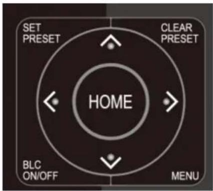
8. Camera control key
UDLR (Up, Down, Left, Right) arrow controls the UDLR movement of the camera.
[HOME] key: Camera returns to centre position or enters the next level menu.
9. Backlight compensation control key
The backlight on/off: Turn on or off the backlight.
- Menu key: Enter/exit OSD menu or return to the previous level menu.
11. Set infrared remote-control address of camera
[*] + [#] + [F1]: # 1 address [*] + [#] + [F2]: # 2 address
[*] + [#] + [F3]: #3 address [*] + [#] + [F4]: #4 address
12. Combination key functions
1) [#] + [#] + [#]: Cancel all presets
2) [*] + [#] + [6]: Restore factory settings
3) [*] + [#] + [9]: Shift between front and upside-down installation
4) [*] + [#] +auto: Enter aging mode
5) [*] + [#] + [3]: Set menu into Chinese
6) [*] + [#] + [4]: Set menu into English
7) [*] + [#] + manual: Restore default IP, username, password
8) [#] + [#] + [0]: Shift video format 1080P60
9) [#] + [#] + [1]: Shift video format 1080P50
10) [#] + [#] + [2]: Shift video format 1080I60
11) [#] + [#] + [3]: Shift video format 1080I50
12) [#] + [#] + [4]: Shift video format 720P60
13) [#] + [#] + [5]: Shift video format 720P50
14) [#] + [#] + [6]: Shift video format 1080P30
15) [#] + [#] + [7]: Shift video format 1080P25
16) [#] + [#] + [8]: Shift video format 720P30
17) [#] + [#] + [9]: Shift video format 720P25
7.2 Use remote control.
Once the camera has powered on and run its self inspection, it will be capable of receiving infrared commands. Press down the remote-control key, the receiving indicator of remote-control flashes, release the key, the indicator stops flashing. Users can set presets, read position, and control horizontal and vertical motion by infrared remote control.
Description of keys:
- The keypress mentioned in this manual means press and release the key on the remote control. For example, "press [HOME] key" means press down [HOME] key and release. If a long press is needed, it will be specified.
- Operation of combination keys mentioned in this manual means operating such keys in order. For example, "press [*] + [#] + [F1]" means press [*] first, then [#], and [F1] at last.
1) Select camera

Select the address number of cameras to be controlled.
2) Camera Control
3) Set, cancel, call preset.

4) Zoom control

Move upwards: Press [▲]; move downwards: Press [▼]
Rotate left: Press [ ] rotate right: Press [ ]
Center position: Press [HOME]
Long press the UDLR key, it will move from low speed to high speed continuously, until it reaches the destination; release in the middle of the movement, the camera will stop moving.
- Save preset: Press [Set preset], then press any number key from 0 to 9, it will reset a preset corresponding to the number key.
Note: with remote control, it can set 10 presets at most.
- Call preset: Press number key 0\~9 directly, it will move to the preset which has been saved.
Note: If this key has not been preset, this operation is invalid.
- Cancel preset: Press [cancel preset], then press any number from 0 to 9, it will cancel the preset corresponding to the number.
Note: Press [#] three times in a row, this will cancel all presets.
Zoom in: Press [zoom +]
Zoom out: Press [zoom -]
Long press these keys will enable continuous zoom to in/zoom out; release midway will stop zoom.
5) Focusing control

Focusing in: Press [focusing +] key (only valid in manual focusing mode)
Focusing out: Press [focusing -] key (only valid in manual focusing mode)
Long press these keys will enable continuous focusing in/ focusing out, release midway will stop focusing.
Autofocusing: Support Manual focusing: Support
7) Set the infrared remote-control address of the camera.

[F1]stop tracking, (whenever use remote control, please stop tracking first)
[F2] Start tracking.
[*] + [#] + [F1]: Set up #1 address.
[*] + [#] + [F2]: Set up #2 address.
[*] + [#] + [F3]: Set #3 address.
[*] + [#] + [F4]: Set up #4 address
8 Set menu
8.1 Main menu
In a normal image, press the [MENU] key, the screen displays the menu content, use the arrow to point to the desired item.
| MENU | |
| Language | English |
| (Setup) | |
| (Camera) | |
| (P/T/Z) | |
| (Video Format) | |
| (Version) | |
Language settings / Language: Select menu language, Chinese/English
Settings: Enter submenu of system parameter settings
Camera parameters: Enter submenu of camera parameter settings
P/T/Z: Enter submenu item of camera parameter settings
Version: Enter submenu of Version
Restore default: Enter restore to default, select "yes" or "no" restore the default
[↑↓] Select: Press [↑↓] to select the menu item
[←→] Change value: Press [←→] to change the value
[Menu] return: Press menu key to return
[Home] OK: Press [Home] key to confirm
8.2 System parameter settings
On the main menu, move the cursor to (Settings), press the [HOME] key to enter the Settings page, as shown below.
SETUP
| Visca Address Fix | OFF |
| PELCO-P Address | 1 |
| PELCO-D Address | 1 |
Protocol: Protocol type VISCA/PELCO-P/PELCO-D/auto Communication address: VISCA=1\~7; PELCO-P = 1\~64; PELCO-D =1\~64
Baud rate: Set item: 2400/4800/9600/115200
VISCA address fix: Set item: On/off
8.3 Camera parameter settings
On the main menu, move the cursor to (CAMERA), press the [HOME] key to enter the CAMERA page, as shown below.
CAMERA
(Exposure)
(Color)
(Image)
(Focus)
(Noise Reduction)
Exposure: Enter exposure submenu item
Image: Enter image submenu item
Colour: Enter colour submenu item
Focus: Enter focus submenu item
Noise reduction: Enter noise
Style: Default, standard, clear, bright,
reduction submenu item
gentle
1) Exposure
On the CAMERA menu, move the cursor to (EXPOSURE), press the [HOME] key to enter the exposure page, as shown below:
| EXPOSURE | |
| Mode | Auto |
| EV | OFF |
| BLC | OFF |
| Flicker | 50Hz |
| G. Limit | |
Mode: Options: Auto, manual, shutter priority, aperture priority, brightness priority
EV: Options: On/off (only valid in auto mode)
Compensation Grade: Options: -7\~7 (only valid in auto mode when "EV" is on.)
BLC: Options: On/off (only valid in auto mode) DRC: Options: 1\~8, off
Flicker: Options: Off, 50Hz, 60Hz (valid in auto, shutter priority and brightness priority modes)
G. Limit: Options: 0\~15(valid in auto, shutter priority and brightness priority modes)
Shutter priority: Options: 1/25, 1/30, 1/50, 1/60, 1/90, 1/100, 1/120, 1/180, 1/250, 1/350, 1/500, 1/1,000, 1/2000, 1/3000, 1/4000, 1/6000, 1/10000 (valid in manual and shutter priority modes)
Aperture priority: Options: Off, F11.0, F9.6, F8.0, F6.8, F5.6, F4.8, F4.0, F3.4, F2.8, F2.4, F2.0, F1.8 (valid in manual and aperture priority modes) Brightness: Options: 0\~23 (only valid in brightness priority mode.)
2) Color
On the CAMERA menu, move the cursor to (COLOR), press the [HOME] key to enter the COLOR page, as shown below:
| COLOR | |
| WB Mode | Auto |
| RG Tuning | 0 |
| BG Tuning | 0 |
| Saturation | 100% |
| Hue 7 | |
WB Mode: Options: auto, 3000K, 4000K, 5000K, 6500K, manual, one-key white balance.
RG Tuning: Options: -10\~10 (only valid in auto mode)
BG Tuning: Options: -10\~10 (only valid in auto mode)
Red gain: Options: 0\~255 (only valid in manual mode)
Blue gain: Options: 0\~255 (only valid in manual mode)
Saturation: Options: 60%, 70%, 80%, 90%, 100%, 110%, 120%, 130%, 140%, 150%, 160%, 170%, 180%, 190%, 200%
Hue: Options: 0\~14
AWB Sensitivity: Options: high, medium, low (only valid in auto mode)
3) Image
On the CAMERA menu, move the cursor to (IMAGE), press [HOME] to enter the IMAGE page, as shown below:
| IMAGE | |
| Brightness | 7 |
| Contrast | 7 |
| Sharpness | 4 |
| Flip-H | OFF |
| Flip-V | OFF |
| B&W-Mode | Color |
| Gamma | Default |
| DZoom | OFF |
| D CI | OFF |
Brightness: Options: 0\~14
Contrast: Options: 0\~14
Sharpness: Options: 0\~15
Flip-H: Options: on/off
Flip-V: Options: on/off
B&W-Mode: Options: color, black &white
Gamma: Options: default, 0.45, 0.50, 0.55, 0.63
DZoom: Options : on/off
DCI: Dynamic contrast: options, off, 1\~8
4) Focus
On the CAMERA menu, move the cursor to (FOCUS), press the [HOME] key to enter the FOCUS page, as shown below:
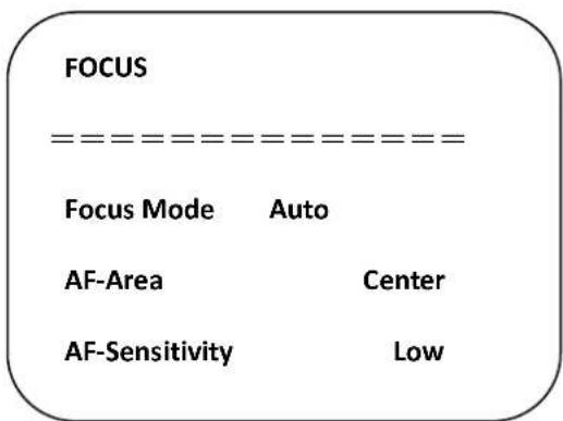
Focus mode: Options: auto/manual
AF-Area: Options: up/center/low
AF-Sensitivity: Options: high/medium/low
5) Noise reduction
On the CAMERA menu, move the cursor to (Noise reduction), press [HOME] key to enter the Noise reduction page, as shown below:

NR-2D: Options: auto, off, 1\~7
NR-3D: Options: off, 1\~8
Dynamic hot pixel: Options: off, 1\~5
8.4 P/T/Z
On the main menu, move the cursor to (P/T/Z), press the [HOME] key to enter the P/T/Z page, as shown below:

Speed by zoom: It only works on the remote control, on, off; when the camera zooms in, the remote control will make the camera rotate at the lower speed.
Zoom speed: Set speed for remote control camera Image freezing: Options: On/off zoom, 1\~8
Acc Curve: Options: Quick/slow
8.5 Video format
On the main menu, move the cursor to (VIDEO FORMAT), press the [HOME] key to enter the VIDEO FORMAT page, as shown below:
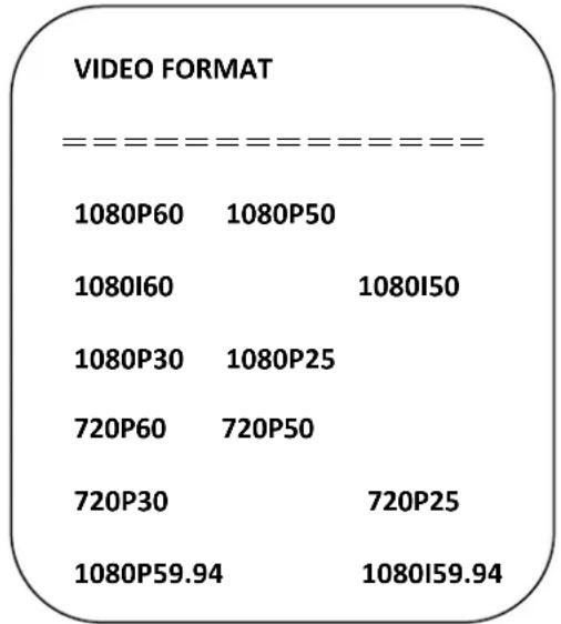
Change parameter value in the menu. To save value when power off, exit menu.
8.6 Version
On the main menu, move the cursor to (Version), press the [HOME] key to enter the Version page. Version information varies from product model and date of production. Version information contains the version number and version upgrade time.
MCU version: It displays MCU version information.
Camera version: It displays camera version information.
Focus version: It displays focus version information.
8.7 Restore default
On the main menu, move the cursor to (restore), press the [HOME] key to enter the Restore page, as shown below.
RESTORE DEFAULT
Restore
Default?
NO
Restore default: Options: Yes/no (Color style and video format can't be restored default).
Note: If the address of former remoter is not 1 but another one from 2, 3, or 4, the corresponding camera address will restore back to 1 when all parameters or system parameters are restored. User should change the remoter address to be 1 (press No.1 according to the camera so to get normal operation)
9. Technical parameters
| Parameter/model | Model-12 X | Model-20 X |
| Tracking camera, lens parameters | ||
| Image sensor | 1/2.8inch high-quality CMOS sensor | |
| Effective pixels | 2,070,000 16: 9 | |
| Video signal | 1080P60/50/30/25/59.94/29.971080I60/50/59.94720P60/50/30/25 /59.94/29.97 | |
| Lens optics zoom | 12X optical zoom f=3.9~46.1mm | 20X optical zoom f=4.7~94mm |
| Visual angle | 6.3° (narrow angle) ~72.5° (wide angle) | 2.9° (narrow angle) ~55.4° (wide angle) |
| Aperture coefficient | F1.8~F2.4 | F1.6 ~ F3.5 |
| Digit zoom | X10 | |
| Minimum illumination | 0.5Lux (F1.8, AGC ON) | |
| Digit noise reduction | 2D & 3D digit noise reduction | |
| White balance | Manual/auto/one-key white balance /3000K/ 4000K/5000K/6500K | |
| Focus | Auto/manual | |
| Aperture | Auto/manual | |
| Electronic shutter | Auto/manual | |
| Backlight compensation | On/off | |
| Wide dynamic | Off/dynamic grade adjustment | |
| Video regulation | Brightness, hue, saturation, contrast ratio, sharpness, Gamma | |
| Signal to noise ratio | >55dB | |
| Panoramic lens | |
| Image sensor | 1/2.8inch high-quality CMOS sensor |
| Effective pixels | 2,100,000 |
| Lens | Manual focus |
| Output port | SDI Model: SDI, LAN,HDMI/ USB Model: HDMI, USB3.0, LAN |
| Field angle (D/H/V) | 112°/82°/57.6° |
| Input/output port and support protocol | |
| Ports | SDI Model: SDI, LAN, 2-channel 3.5mm linear audio input, RS232 (input)HDMI/USB Model: HDMI (support video and audio output), USB3.0, LAN, 2-channel3.5mm linear audio input, RS232 (input) |
| Network port | 100M internet access (10/100BASE-TX) 5GWiFi(optional), support network VISCA control protocol |
| Network protocol | RTSP, RTMP, ONVIF, GB/T28181 |
| Compression image code stream | Dual-stream output |
| Video compression format | H.265, H.264 |
| Control signal port | RS-232/485 |
| Control protocol | VISCA/Pleco-D/Pelco-P; Baud rate: 115,200/9,600/4,800/2,400bps |
| Audio input port | Dual track 3.5mm linear input |
| Audio compression format | AAC, MP3, PCM |
| Power port | HEC3800 power socket (DC12V) |
| Pan/tilt parameters | |
| Horizontal rotation | -170°~+170° |
| Vertical rotation | -30°~+90° |
| Horizontal control speed | 0.1 ~100°/s |
| Vertical control speed | 0.1~45°/s |
| Preset speed | Horizontal: 100°/s, vertical:45°/s |
| Preset quantity | User can set 255 presets at most. |
| Other parameters | |
| Power adapter | Input AC110V-AC220V output DC12V/2.5A |
| Input voltage | DC12V±10% |
| Input current | 1.5A (maximum) |
| Power consumption | 18W (maximum) |
| Storage temperature | -10°C~+60°C |
| Storage humidity | 20%~95% |
| Operating temperature | -10°C~+50°C |
| Operating humidity | 20%~80% |
| Dimension (WxHxD) | 254mm X 144mm X 174mm |
| Weight (approx.) | 1.50kg |
| Operating environment | Indoor |
| Remote maintenance (network port) | Remote upgrade, restart and reset |
| Standard accessories | 12V/2.5A power, RS232 control line, remote control, operation manual, warranty card |
| Optional accessories | Installation support |
10. VISCA protocol command list
When the camera is in normal operation, it can be controlled via RS232C / RS485 port (VISCA IN). Parameters of RS232C serial port are as follows:
Baud rate: 2,400/4,800/9,600/115,200 bit/s; start bit: 1 bit; digit bit: 8 bits; stop bit: 1 bit; verification bit: none.
After powering on, the camera rotates to the left bottom first and then returns to the middle. Zoom lens zooms out to its furthest point and zooms in to the nearest point and finishes self-inspection. If the camera saves #0 preset, after initialization, the camera will go to #0 preset. Now user can use a serial port command to control the camera.
Return command.
| Ack/Completion Message | ||
| Command package | Notes | |
| ACK | z0 41 FF | Returned when the command is accepted. |
| Completion | z0 51 FF Returned when the command has been executed. | |
z = camera address + 8
| Error Messages | ||
| Command package | Notes | |
| Syntax Error z0 60 02 FF | Returned when the command format is different or when a command with illegal command parameters is accepted | |
| Command Not Executable z0 61 41 FF | Returned when a command cannot be executed due to current conditions. For example, when commands controlling the focus manually are received during autofocus. | |
Control command
| Command | Function | Command package | Notes |
| AddressSet | Broadcast | 88 30 01 FF | Address setting |
| IF_Clear | Broadcast | 88 01 00 01 FF | I/F Clear |
| CommandCancel | 8x 21 FF | ||
| CAM_Power | On | 8x 01 04 00 02 FF | Power ON/OFF |
| Off | 8x 01 04 00 03 FF | ||
| CAM_Zoom | Stop | 8x 01 04 07 00 FF | |
| Tele (Standard) | 8x 01 04 07 02 FF | ||
| Wide (Standard) | 8x 01 04 07 03 FF | ||
| Tele (Variable) | 8x 01 04 07 2p FF | p = 0(low) - 7(high) | |
| Wide (Variable) | 8x 01 04 07 3p FF | ||
| Direct | 8x 01 04 47 0p 0q 0r 0s FF | pqrs: Zoom Position | |
| CAM_Focus | Stop | 8x 01 04 08 00 FF | |
| Far(Standard) | 8x 01 04 08 02 FF | ||
| Near(Standard) | 8x 01 04 08 03 FF | ||
| Far(Variable) | 8x 01 04 08 2p FF | p = 0(low) - 7(high) | |
| Near (Variable) | 8x 01 04 08 3p FF | ||
| Direct | 8x 01 04 48 0p 0q 0r 0s FF | pqrs: Focus Position | |
| Auto Focus | 8x 01 04 38 02 FF | ||
| Manual Focus | 8x 01 04 38 03 FF | ||
| CAM_Zoom Focus Direct | 8x 01 04 47 0p 0q 0r 0s0t 0u 0v 0w FF | pqrs: Zoom Position tuvw: Focus Position | |
| CAM_WB | Auto | 8x 01 04 35 00 FF | |
| 3000K | 8x 01 04 35 01 FF | ||
| 4000k | 8x 01 04 35 02 FF | ||
| One Push mode | 8x 01 04 35 03 FF | ||
| 5000k | 8x 01 04 35 04 FF | ||
| Manual | 8x 01 04 35 05 FF | ||
| 6500k | 8x 01 04 35 06 FF | ||
| CAM_RGain | Reset | 8x 01 04 03 00 FF | Manual Control of R Gain |
| Up | 8x 01 04 03 02 FF | ||
| Down | 8x 01 04 03 03 FF | ||
| Direct | 8x 01 04 43 00 00 0p 0q FF | pq: R Gain | |
| CAM_Bgain | Reset | 8x 01 04 04 00 FF | Manual Control of B Gain |
| Up | 8x 01 04 04 02 FF | ||
| Down | 8x 01 04 04 03 FF | ||
| Direct | 8x 01 04 44 00 00 0p 0q FF | pq: B Gain | |
| CAM_AE | Full Auto 8x 01 04 39 | 00 FF | Automatic Exposure mode |
| Manual | 8x 01 04 39 03 FF | Manual Control mode | |
| Shutter priority 8x 01 04 39 0A FF | Shutter Priority Automatic Exposure mode | ||
| Iris priority 8x 01 04 39 0B FF | Iris Priority Automatic Exposure mode | ||
| Bright | 8x 01 04 39 0D FF | Bright mode | |
| CAM_Shutter | Reset | 8x 01 04 0A 00 FF | Shutter Setting |
| Up | 8x 01 04 0A 02 FF | ||
| Down | 8x 01 04 0A 03 FF | ||
| Direct | 8x 01 04 4A 00 00 0p 0q FF | pq: Shutter Position | |
| CAM_Iris | Reset | 8x 01 04 0B 00 FF | Iris Setting |
| Up | 8x 01 04 0B 02 FF | ||
| Down | 8x 01 04 0B 03 FF | ||
| Direct | 8x 01 04 4B 00 00 0p 0q FF | pq: Iris Position | |
| CAM_Gain | Reset | 8x 01 040C 00 FF | Gain Setting |
| Up | 8x 01 04 0C 02 FF | ||
| Down | 8x 01 04 0C 03 FF | ||
| Direct | 8x 01 04 0C 00 00 0p 0q FF | pq: Gain Position | |
| CAM_Bright | Reset | 8x 01 04 0D 00 FF | Bright Setting |
| Up | 8x 01 04 0D 02 FF | ||
| Down | 8x 01 04 0D 03 FF | ||
| Direct | 8x 01 04 4D 00 00 0p 0q FF | pq: Bright Position | |
| CAM_ExpComp | On | 8x 01 04 3E 02 FF | Exposure Compensation ON/OFF |
| Off 8x 01 04 3E 03 FF | |||
| Reset | 8x 01 04 0E 00 FF | Exposure Compensation Amount Setting | |
| Up | 8x 01 04 0E 02 FF | ||
| Down | 8x 01 04 0E 03 FF | ||
| Direct | 8x 01 04 4E 00 00 0p 0q FF | pq: ExpComp Position | |
| CAM_Back Light | On | 8x 01 04 33 02 FF | Back Light Compensation |
| Off | 8x 01 04 33 03 FF | ||
| CAM_NR (2D) | 8x 01 04 53 0p FF | P=0-7 0:OFF | |
| CAM_NR (3D) | 8x 01 04 54 0p FF | P=0-8 0:OFF | |
| CAM_Gamma 8x 01 04 | 5B 0p FF | p = 0 - 4 0: Default1: 0.45 2: 0.503: 0.55 4: 0.63 | |
| CAM_Flicker | OFF | 8x 01 04 23 00 FF | OFF |
| 50HZ | 8x 01 04 23 01 FF | 50HZ | |
| 60HZ | 8x 01 04 23 02 FF | 60HZ | |
| CAM_Aperture | Reset | 8x 01 04 02 00 FF | Aperture Control |
| Up | 8x 01 04 02 02 FF | ||
| Down | 8x 01 04 02 03 FF | ||
| Direct | 8x 01 04 42 00 00 0p 0q FF | pq: Aperture Gain | |
| CAM_Memory | Reset | 8x 01 04 3F 00 pq FF | pq: Memory Number(=0 to 254)Corresponds to 0 to 9 on the Remote Commander |
| Set | 8x 01 04 3F 01 pq FF | ||
| Recall 8x 01 04 3F 02 | pq FF | ||
| CAM_LR_Reverse | On | 8x 01 04 61 02 FF | Image Flip Horizontal ON/OFF |
| Off | 8x 01 04 61 03 FF | ||
| CAM_PictureFlip | On | 8x 01 04 66 02 FF | Image Flip Vertical ON/OFF |
| Off | 8x 01 04 66 03 FF | ||
| CAM_ColorSaturation | Direct | 8x 01 04 4900 00 00 0p FF | P=0-E0:60% 1:70%2:80% 3:90%4:100%5:110% 6:120%7:130% 8:140%9:150% 10:160%11:160% 12:180%13:190% 14:200% |
| CAM_IDWrite | 8x 01 04 22 0p 0q 0r 0s FF | pqrs: Camera ID (=0000 to FFFF) | |
| SYS_Menu | ON 8x 01 04 06 06 02 | FF | Turn on the menu screen |
| OFF 8x 01 04 06 06 03 | FF | Turn off the menu screen | |
| IR_Receive | ON | 8x 01 0608 02 FF | IR(remote commander)receive On/Off |
| OFF 8x 01 0608 03 FF | |||
| IR_ReceiveReturn | On 8x 01 7D 01 03 00 | 00 FF | IR(remote commander)receive the message via the VISCA communication ON/OFF |
| Off 8x 01 7D 01 13 00 | 00 FF | ||
| CAM_SettingReset | Reset | 8x 01 04 A0 10 FF | Reset Factory Setting |
| CAM_Brightness | Direct | 8x 01 04 A1 00 00 0p 0q FF | pq: Brightness Position |
| CAM_Contrast | Direct | 8x 01 04 A2 00 00 0p 0q FF | pq: Contrast Position |
| CAM_Flip | OFF | 8x 01 04 A4 00 FF | Single Command For Video Flip |
| Flip-H | 8x 01 04 A4 01 FF | ||
| Flip-V | 8x 01 04 A4 02 FF | ||
| Flip-HV | 8x 01 04 A4 03 FF | ||
| CAM_VideoSystem | Set camera video system | 8x 01 06 35 00 0p FF | P: 0~E Video format0:1080P608:720P301:1080P509:720P252:1080i60A: 1080P59.943:1080i50B: 1080i59.944:720P60C: 720P59.945:720P50D: 1080P29.976:1080P30E: 720P29.977:1080P25 |
| Pan_tiltDrive | Up | 8x 01 06 01 VV WW 03 01 FF | VV: Pan speed 0x01(low speed) to 0x18(high speed)WW: Tilt speed 0x01(low speed) to 0x14(high speed)YYYY: Pan PositionZZZZ: Tilt Position |
| Down | 8x 01 06 01 VV WW 03 02 FF | ||
| Left | 8x 01 06 01 VV WW 01 03 FF | ||
| Right | 8x 01 06 01 VV WW 02 03 FF | ||
| Upleft | 8x 01 06 01 VV WW 01 01 FF | ||
| Upright | 8x 01 06 01 VV WW 02 01 FF | ||
| DownLeft | 8x 01 06 01 VV WW 01 02 FF | ||
| DownRight | 8x 01 06 01 VV WW 02 02 FF | ||
| Stop | 8x 01 06 01 VV WW 03 03 FF | ||
| AbsolutePosition | 8x 01 06 02 VV WW0Y 0Y 0Y 0Y 0Z 0Z 0Z FF | ||
| RelativePosition | 8x 01 06 03 VV WW0Y 0Y 0Y 0Y 0Z 0Z 0Z FF | ||
| Home | 8x 01 06 04 FF | ||
| Reset | 8x 01 06 05 FF | ||
| Pan-tiltLimitSet | Set | 8x 01 06 07000W0Y 0Y 0Y 0Y 0Z 0Z 0Z FF | W:1 UpRight0:DownLeftYYYY: Pan Limit Position(TBD)ZZZZ: Tilt Limit Position(TBD) |
| Clear | 8x 01 06 07010W07 0F 0F 0F 07 0F 0F 0F FF | ||
Search command
| Command | Command package | Return package | Notes |
| CAM_PowerInq 8x 09 04 00 FF | y0 50 02 FF | On | |
| y0 50 03 FF | Off(Standby) | ||
| CAM_ZoomPosInq | 8x 09 04 47 FF | y0 50 0p 0q 0r 0s FF | pqrs: Zoom Position |
| CAM_FocusAFModelInq 8x 09 04 | 38 FF | y0 50 02 FF | Auto Focus |
| y0 50 03 FF | Manual Focus | ||
| CAM_FocusPosInq | 8x 09 04 48 FF | y0 50 0p 0q 0r 0s FF | pqrs: Focus Position |
| CAM_WBModelInq 8x 09 04 35 FF | y0 50 00 FF | Auto | |
| y0 50 01 FF | 3000K | ||
| y0 50 02 FF | 4000K | ||
| y0 50 03 FF | One Push Mode | ||
| y0 50 04 FF | 5000K | ||
| y0 50 05 FF | Manual | ||
| y0 50 00 FF | 6500K | ||
| CAM_RGainInq | 8x 09 04 43 FF | y0 50 00 00 0p 0q FF | pq: R Gain |
| CAM_BGainInq | 8x 09 04 44 FF | y0 50 00 00 0p 0q FF | pq: B Gain |
| CAM_AEModelInq 8x 09 04 39 FF | y0 50 00 FF | Full Auto | |
| y0 50 03 FF | Manual | ||
| y0 50 0A FF | Shutter priority | ||
| y0 50 0B FF | Iris priority | ||
| y0 50 0D FF | Bright | ||
| CAM_ShutterPosInq | 8x 09 04 4A FF | y0 50 00 00 0p 0q FF | pq: Shutter Position |
| CAM_IrisPosInq | 8x 09 04 4B FF | y0 50 00 00 0p 0q FF | pq: Iris Position |
| CAM_BrightPosInq | 8x 09 04 4D FF | y0 50 00 00 0p 0q FF | pq: Bright Position |
| CAM_ExpCompModelInq 8x 09 04 | 3E FF | y0 50 02 FF | On |
| y0 50 03 FF | Off | ||
| CAM_ExpCompPosInq | 8x 09 04 4E FF | y0 50 00 00 0p 0q FF | pq: ExpComp Position |
| CAM_BacklightModelInq 8x 09 04 | 33 FF | y0 50 02 FF | On |
| y0 50 03 FF | Off | ||
| CAM_NRLevel(2D) Inq | 8x 09 04 53 FF | y0 50 0p FF | P: 2DNRLevel |
| CAM_NRLevel(3D) Inq | 8x 09 04 54 FF | y0 50 0p FF | P:3D NRLevel |
| CAM_FlickerModelInq | 8x 09 04 55 FF | y0 50 0p FF | p: Flicker Settings(0: OFF, 1: 50Hz,2:60Hz) |
| CAM_ApertureInq | 8x 09 04 42 FF | y0 50 00 00 0p 0q FF | pq: Aperture Gain |
| CAM_PictureEffectModelInq 8x 09 04 63 FF | y0 50 00 FF | Off | |
| y0 50 04 FF | B&W | ||
| CAM_MemoryInq | 8x 09 04 3F FF | y0 50 0p FF | p: Memory number last operated. |
| SYS_MenuModelInq 8x 09 0606 FF | y0 50 02 FF | On | |
| y0 50 03 FF | Off | ||
| CAM_LR_Reverselnq 8x 09 04 61 FF | y0 50 02 FF | On | |
| y0 50 03 FF | Off | ||
| CAM_PictureFlipInq 8x 09 04 66 FF | y0 50 02 FF | On | |
| y0 50 03 FF | Off | ||
| CAM_ColorSaturationInq | 8x 09 04 49 FF | y0 50 00 00 00 0p FF | p: Color Gain setting 0h (60%) to Eh (200%) |
| CAM_IDInq | 8x 09 04 22 FF | y0 50 0p FF | p: Gamma ID |
| IR_ReceiveInq 8x 09 0608 FF | y0 50 02 FF | On | |
| y0 50 03 FF | Off | ||
| IR_ReceiveReturn | y0 077D 01 04 00 FF | Power ON/OFF | |
| y0 077D 01 04 07 FF | Zoom Tele/Wide | ||
| y0 077D 01 04 38 FF | AF ON/OFF | ||
| y0 077D 01 04 33 FF | Camera_Backlight | ||
| y0 077D 01 04 3F FF | Camera_Memory | ||
| y0 077D 01 06 01 FF | Pan_titleDriver | ||
| CAM_BrightnessInq | 8x 09 04A1 FF | y0 50 00 00 0p 0q FF | pq: Brightness Position |
| CAM_ContrastInq | 8x 09 04A2 FF | y0 50 00 00 0p 0q FF | pq: Contrast Position |
| CAM_FlipInq 8x 09 04A4 FF | y0 50 00 FF | Off | |
| y0 50 01 FF | Flip-H | ||
| y0 50 02 FF | Flip-V | ||
| y0 50 03 FF | Flip-HV | ||
| CAM_GammaInq | 8x 09 04 5B FF | y0 50 0p FF | p: Gamma setting |
| CAM_VersionInq | 8x 09 00 02 FF | y0 50 ab cd mn pq rs tu vw FF | ab cd: vender ID (0220)mn pq : model ID ST (0951)U3(3950)rs tu : ARM Version vw: reserve |
| VideoSystemInq | 8x 09 06 23 FF | y0 50 0p FF | P: 0~E Video format0:1080P608:720P301:1080P509:720P252:1080i60A: 1080P59.943:1080i50B: 1080i59.944:720P60C: 720P59.945:720P50D: 1080P29.976:1080P30E: 720P29.977:1080P25 |
| Pan-tiltMaxSpeedInq | 8x 09 06 11 FF | y0 50 ww zz FF | ww: Pan Max Speedzz:Tilt Max Speed |
| Pan-tiltPosInq 8x 09 06 12 FF | y0 50 0w 0w 0w 0w0z Oz Oz Oz FF | www:PanPositionzzzz: Tilt Position |
Note: [x] on table above means address of camera to be operated, [y] = [x+8].
- Pelco-D protocol command list
| Function Byte1 Byte2 Byte3 Byte4 Byte5 Byte6 Byte7 | |||||||
| Up | 0xFF | Address | 0x00 | 0x08 | Pan Speed | Tilt Speed | SUM |
| Down | 0xFF | Address | 0x00 | 0x10 | Pan Speed | Tilt Speed | SUM |
| Left | 0xFF | Address | 0x00 | 0x04 | Pan Speed | Tilt Speed | SUM |
| Right | 0xFF | Address | 0x00 | 0x02 | Pan Speed | Tilt Speed | SUM |
| Upleft | 0xFF | Address | 0x00 | 0x0C | Pan Speed | Tilt Speed | SUM |
| Upright | 0xFF | Address | 0x00 | 0x0A | Pan Speed | Tilt Speed | SUM |
| Down Left | 0xFF | Address | 0x00 | 0x14 | Pan Speed | Tilt Speed | SUM |
| Down Right | 0xFF | Address | 0x00 | 0x12 | Pan Speed | Tilt Speed | SUM |
| Zoom In | 0xFF | Address | 0x00 | 0x20 | 0x00 | 0x00 | SUM |
| Zoom Out | 0xFF | Address | 0x00 | 0x40 | 0x00 | 0x00 | SUM |
| Focus Far | 0xFF | Address | 0x00 | 0x80 | 0x00 | 0x00 | SUM |
| Focus Near | 0xFF | Address | 0x01 | 0x00 | 0x00 | 0x00 | SUM |
| Stop | 0xFF | Address | 0x00 | 0x00 | 0x00 | 0x00 | SUM |
| Set Preset | 0xFF | Address | 0x00 | 0x03 | 0x00 | Preset ID | SUM |
| Clear Preset | 0xFF | Address | 0x00 | 0x05 | 0x00 | Preset ID | SUM |
| Call Preset | 0xFF | Address | 0x00 | 0x07 | 0x00 | Preset ID | SUM |
| Query Pan Position | 0xFF | Address | 0x00 | 0x51 | 0x00 | 0x00 | SUM |
| Query Pan Position Response | 0xFF Address | 0x00 0x59 | Value High Byte | Value Low Byte | SUM | ||
| Query Tilt Position | 0xFF | Address | 0x00 | 0x53 | 0x00 | 0x00 | SUM |
| Query Tilt Position Response | 0xFF Address | 0x00 0x5B | Value High Byte | Value Low Byte | SUM | ||
| Query Zoom Position | 0xFF | Address | 0x00 | 0x55 | 0x00 | 0x00 | SUM |
| Query Zoom Position Response | 0xFF Address | 0x00 0x5D | Value High Byte | Value Low Byte | SUM | ||
12. Pelco-P protocol command list
| Function | Byte1 | Byte2 | Byte3 | Byte4 | Byte5 | Byte6 | Byte7 | Byte8 |
| Up | 0xA0 | Address | 0x00 | 0x08 | Pan Speed | Tilt Speed | 0xAF | XOR |
| Down | 0xA0 | Address | 0x00 | 0x10 | Pan Speed | Tilt Speed | 0xAF | XOR |
| Left | 0xA0 | Address | 0x00 | 0x04 | Pan Speed | Tilt Speed | 0xAF | XOR |
| Right | 0xA0 | Address | 0x00 | 0x02 | Pan Speed | Tilt Speed | 0xAF | XOR |
| Upleft | 0xA0 | Address | 0x00 | 0x0C | Pan Speed | Tilt Speed | 0xAF | XOR |
| Upright | 0xA0 | Address | 0x00 | 0x0A | Pan Speed | Tilt Speed | 0xAF | XOR |
| DownLeft | 0xA0 | Address | 0x00 | 0x14 | Pan Speed | Tilt Speed | 0xAF | XOR |
| Down Right | 0xA0 | Address | 0x00 | 0x12 | Pan Speed | Tilt Speed | 0xAF | XOR |
| Zoom In | 0xA0 | Address | 0x00 | 0x20 | 0x00 | 0x00 | 0xAF | XOR |
| Zoom Out | 0xA0 | Address | 0x00 | 0x40 | 0x00 | 0x00 | 0xAF | XOR |
| Stop | 0xA0 | Address | 0x00 | 0x00 | 0x00 | 0x00 | 0xAF | XOR |
| Focus Far | 0xA0 | Address | 0x01 | 0x00 | 0x00 | 0x00 | 0xAF | XOR |
| Focus Near | 0xA0 | Address | 0x02 | 0x00 | 0x00 | 0x00 | 0xAF | XOR |
| Set Preset | 0xA0 | Address | 0x00 | 0x03 | 0x00 | Preset ID | 0xAF | XOR |
| Clear Preset | 0xA0 | Address | 0x00 | 0x05 | 0x00 | Preset ID | 0xAF | XOR |
| Call Preset | 0xA0 | Address | 0x00 | 0x07 | 0x00 | Preset ID | 0xAF | XOR |
| Query Pan Position | 0xA0 | Address | 0x00 | 0x51 | 0x00 | 0x00 | 0xAF | XOR |
| Query Pan Position Response | 0xA0 Address 0x00 0x59 | Value High Byte | Value Low Byte | 0xAF XOR | ||||
| Query Tilt Position | 0xA0 | Address | 0x00 | 0x53 | 0x00 | 0x00 | 0xAF | XOR |
| Query Tilt Position Response | 0xA0 Address 0x00 0x5B | Value High Byte | Value Low Byte | 0xAF XOR | ||||
| Query Zoom Position | 0xA0 | Address | 0x00 | 0x55 | 0x00 | 0x00 | 0xAF | XOR |
| Query Zoom Position Response | 0xA0 Address 0x00 0x5D | Value High Byte | Value Low Byte | 0xAF XOR | ||||
13. Maintenance and troubleshooting
13.1 Maintenance
1) Please disconnect the power of the camera if it is not in long-term use. Disconnect the AC power adapter from the AC socket.
2) To avoid scratches, use a soft cloth or cotton to wipe off the dust on the camera case.
3) Clean the camera lens with a dry soft cloth. If the blemish persists, use a mild detergent to wipe gently.
Do not use strong or corrosive detergent which may scratch the lens and affect image result.
13.2 Troubleshooting
1) No image displayed by the video output:
Solution: a. Check camera power for connection, and check if the power indicator is lit.
b. Power off, restart the device and check if it performs self-inspection as per usual.
c. Check if the dial switch at the bottom is in the normal operating mode
d. Check if the connection line of video output and video display functions.
2) Image is unstable:
Solution: a. Check if the connection line of video output and video display functions.
3) Lens zoom image dithering:
Solution: a. Check if the camera is installed securely.
b. Check if there is a vibrating machine or object nearby the camera.
4) Remote control is out of service:
Solution: a. Set remote control address to be 1, and check if it works (if the device restores to default, remote control address will be restored to 1).
b. Check if remote control battery is installed or battery is low
c. Check if the camera is in the normal operating mode
d. Check if the menu exits. It only works when the menu exits; if the webpage outputs an image, it will not display the menu or perform any operation. Menu exits in the 30s automatically. The remote control works.
5) Serial port is not controllable:
Solution: a. Check if it is a standard control cable provided.
b. Check if the serial port protocol, baud rate and address are consistent with the camera.
c. Check if the control cable is correctly connected.
d. Check if the camera is in the normal operating mode
6) Failure to log in webpage:
Solution: a. Use the display to check if the camera outputs image normally.
b. Check if the network cable connects correctly (flicker of the yellow indicator at internet access means network cable connection is correct).
c. Check if the computer adds a network segment and if the network segment is consistent with a camera IP address.
d. Click "start" in computer, select "operate", and enter cmd; click "confirm", DOS command window appears; input ping 192.168.5.163, press Enter, the information below means network connection functions well.
C:\Users\qq214>ping 192.168.5.163
Pinging 192.168.5.163 with 32 bytes of data:
Reply from 192.168.5.163: bytes=32 time=2ms TTL=64
Reply from 192.168.5.163: bytes=32 time=1ms TTL=64
Reply from 192.168.5.163: bytes=32 time<1ms TTL=64
Reply from 192.168.5.163: bytes=32 time=4ms TTL=64
Ping statistics for 192.168.5.163:
    Packets: Sent = 4, Received = 4, Lost = 0 (0% loss),
Approximate round trip times in milli-seconds:
    Minimum = 0ms, Maximum = 4ms, Average = 1ms
C:\Users\qq214>
After-sales Service
Should you experience problems using the Alfatron ALF-12/20X-HD-TC, ALF-12/20X-SD-TC please refer to the manual and troubleshooting and maintenance section (6). Should the error persist, note that any transport costs of the equipment to the distributor are borne by the user during the warranty.
1) Product Limited Warranty: Alfatron warrants that its products will be free from defects in materials and workmanship for seven years, which starts from the first day of purchase.
Proof of purchase in the form of a bill of sale or receipted invoice which is evidence that the unit is within the warranty period must be presented to obtain warranty service.
2) What the warranty does not cover (servicing available for a fee):
- Warranty expiration.
● Factory applied serial number has been altered or removed from the product. -
Damage, deterioration, or malfunction caused by:
-
Normal wear and tear.
- Use of supplies or parts not meeting product specifications.
- No certificate or invoice as the proof of warranty.
- The product model showed on the warranty card does not match with the product or if the product had been altered.
- Damage caused by force majeure.
- Servicing not authorized by Alfatron.
- Any other causes which do not relate to a product defect.
- Delivery, installation or labour charges for installation or setup of the product.
3) Technical Support: Contact our after-sales department at
www.alfatronelectronics.com
Warranty
1.1 This limited warranty covers defects in materials and workmanship in this product.
1.2 Should warranty service be required, proof of purchase must be presented to the Company. The serial number on the product must be clearly visible and not have been tampered with in any way whatsoever.
1.3 This limited warranty does not cover any damage, deterioration or malfunction resulting from any alteration, modification, improper or unreasonable use or maintenance, misuse, abuse, accident, neglect, exposure to excess moisture, fire, improper packing and shipping (such claims must be presented to the carrier), lightning, power surges, or other acts of nature. This limited warranty does not cover any damage, deterioration or malfunction resulting from the installation or removal of this product from any installation, any unauthorized tampering with this product, any repairs attempted by anyone unauthorized by the Company to make such repairs, or any other cause which does not relate directly to a defect in materials and/or workmanship of this product. This limited warranty does not cover equipment enclosures, cables or accessories used in conjunction with this product.
This limited warranty does not cover the cost of normal maintenance. Failure of the product due to insufficient or improper maintenance is not covered.
1.4 The Company does not warrant that the product covered hereby, including, without limitation, the technology and/or integrated circuit(s) included in the product, will not become obsolete or that such items are or will remain compatible with any other product or technology with which the product may be used.
1.5 Only the original purchaser of this product is covered under this limited warranty. This limited warranty is not transferable to subsequent purchasers or owners of this product.
1.6 Unless otherwise specified, the goods are warranted in accordance with the manufacturer's product specific warranties against any defect attributable to faulty workmanship or materials, fair wear and tear being excluded.
1.7 This limited warranty only covers the cost of faulty goods and does not include the cost of labor and travel to return the goods to the Company's premises.
1.8 In the event of any improper maintenance, repair or service being carried out by any third persons during the warranty period without the Company's written authorization, the limited warranty shall be void.
1.9 A 7 (seven) year limited warranty is given on the aforesaid product where used correctly according to the Company's instructions, and only with the use of the Company's components.
1.10 The Company will, at its sole option, provide one of the following three remedies to whatever extent it shall deem necessary to satisfy a proper claim under this limited warranty:
1.10.1 Elect to repair or facilitate the repair of any defective parts within a reasonable period of time, free of any charge for the necessary parts and labor to complete the repair and restore this product to its proper operating condition.; or
1.10.2 Replace this product with a direct replacement or with a similar product deemed by the Company to perform substantially the same function as the original product; or
1.10.3 Issue a refund of the original purchase price less depreciation to be determined based on the age of the product at the time remedy is sought under this limited warranty.
1.11 The Company is not obligated to provide the Customer with a substitute unit during the limited warranty period or at any time thereafter.
1.12 If this product is returned to the Company this product must be insured during shipment, with the insurance and shipping charges prepaid by the Customer. If this product is returned uninsured, the Customer assumes all risks of loss or damage during shipment. The Company will not be responsible for any costs related to the removal or re-installation of this product from or into any installation. The Company will not be responsible for any costs related to any setting up this product, any adjustment of user controls or any programming required for a specific installation of this product.
1.13 Please be aware that the Company's products and components have not been tested with competitor's products and therefore the Company cannot warrant products and/or components used in conjunction with competitor's products.
1.14 The appropriateness of the goods for the purpose intended is only warranted to the extent that the goods are used in accordance with the Company's installation, classification and usage instructions.
1.15 Any claim by the Customer which is based on any defect in the quality or condition of the goods or their failure to correspond with specification shall be notified in writing to the Company within 7 days of delivery or (where the defect or failure was not apparent on reasonable inspection by the Customer) within a reasonable time after discovery of the defect or failure, but, in any event, within 6 months of delivery.
1.16 If delivery is not refused, and the Customer does not notify the Company accordingly, the Customer may not reject the goods and the Company shall have no liability and the Customer shall pay the price as if the goods had been delivered in accordance with the Agreement.
1.17 THE MAXIMUM LIABILITY OF THE COMPANY UNDER THIS LIMITED WARRANTY SHALL NOT EXCEED THE ACTUAL PURCHASE PRICE PAID FOR THE PRODUCT
- FCC Statement
- CE F© EAC CAN ICES-3 (B)/NMB-3(B)
- Radiation Exposure
- Radiation Exposure:
- Preface
- Safety precautions
- Electrical safety
- Installation Safety
- Magnetic Interference
- Table of Contents
- System overview
- System introduction
- Product advantages
- Product features
- Port introduction – ALF-XX-HD-TC
- Port introduction – ALF-XX-SD-TC
- Dimensions
- System connection
- Installation layout
- System wiring
- Configuration tools
- Set IP address of the tracking machine
- Configure tracking parameters.
- Set the preset position for close up
- Set panoramic lens area
- Set tracking parameters
- Tracking settings:
- Advanced parameters:
- Network update
- Description of recording and broadcasting host
- Auto tracking control
- Network receiving address
- Command
- Action code docking
- Configure recording and broadcasting host address
- Configure action code
- Description of remote control
- Description of keys
- Standby key
- Select camera
- Number key
- \*key and #key
- Focusing control key: adjust focusing.
- Zoom key
- Set and clear preset key
- Camera control key
- Backlight compensation control key
- Set infrared remote-control address of camera
- Combination key functions
- Use remote control.
- Description of keys:
- 1) Select camera
- 5) Focusing control
- 7) Set the infrared remote-control address of the camera.
- Set menu
- Main menu
- System parameter settings
- Camera parameter settings
- 1) Exposure
- 2) Color
- 3) Image
- 4) Focus
- 5) Noise reduction
- P/T/Z
- Video format
- Version
- Restore default
- Technical parameters
- VISCA protocol command list
- Return command.
- Pelco-P protocol command list
- Maintenance and troubleshooting
- Maintenance
- Troubleshooting
- After-sales Service
- Warranty
Brand : Alfatron
Model : ALF-20X-HD-TC
Category : Security Camera