BP192VL2U01 - Inverter CyberPower - Free user manual and instructions
Find the device manual for free BP192VL2U01 CyberPower in PDF.

User questions about BP192VL2U01 CyberPower
0 question about this device. Answer the ones you know or ask your own.
Ask a new question about this device
Download the instructions for your Inverter in PDF format for free! Find your manual BP192VL2U01 - CyberPower and take your electronic device back in hand. On this page are published all the documents necessary for the use of your device. BP192VL2U01 by CyberPower.
USER MANUAL BP192VL2U01 CyberPower
natural_image
Illustration of a server rack with visible network ports and ventilation slots, labeled 'CyberPower' on the side (no other text or symbols)SAVE THESE INSTRUCTIONS
Please read this manual and follow the instructions for installation and operation.
PRODUCT SAFETY
CAUTION

To reduce the risk of fire, connect the EBM AC input to a branch circuit with 20 amperes maximum overcurrent protection in accordance with the National Electric Code, ANSI/NFPA 70.
A battery can present a risk of electric shock and high short circuit current. The following precaution should be observed when working on batteries:
Remove watches, rings or other metal objects.
Use tools with insulated handles.
Wear rubber gloves and boots.
Do not lay tools or metal parts on top of batteries.
Disconnect the AC power prior to connecting or disconnecting terminals.
Ensure the ground terminal is disconnected during installation and maintenance to reduce likelihood of shock. If battery is installed and grounded, disconnected the ground terminal before working on the UPS.
RISK OF ELECTRIC SHOCK
See Installation Instructions Before Connecting To The Supply. Do Not Disconnect Battery Connector Under Load.
Batteries replaceable by SERVICE PERSONNEL.
BATTERY

Do not dispose of batteries in fire as the battery may explode.
Do not open or mutilate the battery, released electrolyte is harmful to the skin and eyes.
TABLE OF CONTENTS
SAFETY INSTRUCTIONS .... I
Product Safety....I
INTRODUCTION....1
UPS Extended Battery Modules 1
Unpacking Procedures 1
What's In The Box....2
EXTENDED BATTERY MODULE INSTALLATION.... 3
Battery Module 3
Connection With UPS 4
HARDWARE INSTALLATION 7
Rackmount Installation For 4-Post Rack....7
Rackmount Installation For 2-Post Rack....9
Vertical/Tower Installation....10
MAINTENANCE....11
Battery Replacement....1 1
TECHNICAL SPECIFICATIONS....14
TROUBLESHOOTING....15
PRODUCT REGISTRATION....15
LIMITED WARRANTY....16
CONFORMANCE APPROVAL.... 20
INTRODUCTION
UPS EXTENDED BATTERY MODULES
Extended Battery Modules (EBMs) from CyberPower (BP192VL2U01) increase battery runtimes during power outages. Each rack/tower convertible EBM uses 2U of rack space and can be installed in a tower form factor to match the UPS installation. The DC plug-and-play power connectors allow to daisy-chain additional EBMs to a UPS system. EBMs compatible with Smart App Online UPS systems also have a built-in battery charger, providing Fast Charge Technology to quickly restore the backup power supply. Every CyberPower EBM has a three-year warranty.
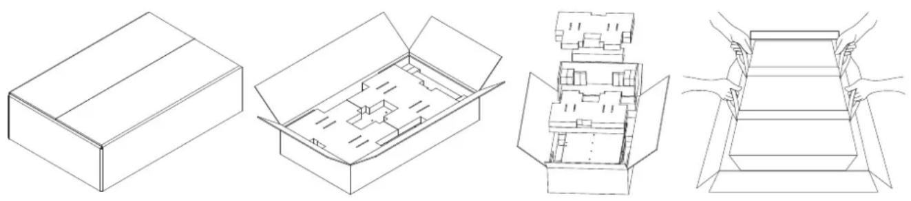
UNPACKING PROCEDURES

Information, advice, help
The Extended Battery Module is very heavy, please handle with care. Wear safety shoes and use a hydraulic equipment lift if one is available. At least two people are required for all handling operations, including unpacking, lifting, and installation in a rack system. Do not use the lifting straps to carry the unit around; they are provided to manually unpack the unit only.
USE LIFTING STRAPS TO REMOVE THE UNIT FROM THE BOX.
natural_image
Four technical line drawings of open and closed boxes, showing internal compartments and structural details (no text or symbols)INTRODUCTION CONT.
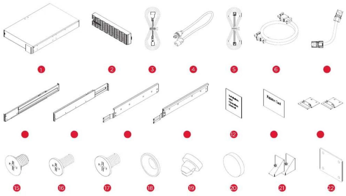
WHAT'S IN THE BOX
| ITEM | CONTENT QTY | ITEM | CONTENT QTY | ||
| 1 | EBM | 1 | 12 | Installation and Operation Manual | 1 |
| 2 | Front panel | 1 | 13 | Registration warranty card | 1 |
| 3 | IEC320 C14 to IEC320 C13 power cord | 1 | 14 | Rackmount ears | 2 |
| 4 | NEMA L6-20P to IEC320 C13 power cord | 1 | 15 | Flat head screws M5X7L | 8 |
| 5 | BM Cable | 1 | 16 | Pan head screws M5X8L | 12 |
| 6 | BMP Cable | 1 | 17 | Pan head screws M5X6L | 6 |
| 7 | DC Power Core | 1 | 18 | Plastic washers | 8 |
| 8 | Rackmount left rail | 1 | 19 | Screw hole dust covers | 18 |
| 9 | Rackmount right rail | 1 | 20 | Rubber pads | 12 |
| 10 | Left hanging bracket | 1 | 21 | Stand | 2 |
| 11 | Right hanging bracket | 1 | 22 | Tie plate | 1 |
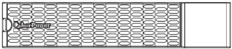
EXTENDED BATTERY MODULE INSTALLATION
BATTERY MODULE
text_image
CyberPower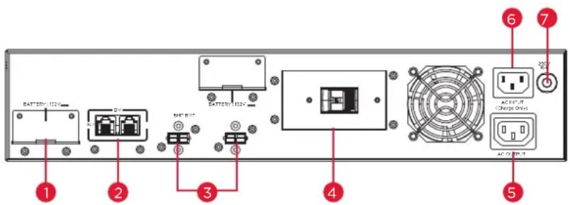
text_image
BATTERY 120V BATTERY 120V AC INPUT C/O Charge Only AC OUTPUTBP192VL2U01
1. BP192VL2U01 EBM DC Input Connector
Connect to the UPS or to the other Extended battery modules
2. BM Ports
Connection port for built-in battery management module on UPS and Extended Battery Module.
3. BMP Connectors
BMP connector for built-in battery management module on UPS and Extended Battery Module.
4. DC Breaker
Use the DC breaker to disconnect battery output.
5. AC Fast Charge outlet (IEC320 C13)
Use this outlet to connect to the Fast Charge AC input of a downstream EBM.
6. AC Fast Charge Input (IEC320 C14)
Connect to a 208V, 20A, AC power source, or connect to the AC Fast Charge output from an upstream EBM.
7. AC Circuit Breaker
Provides overload and fault protection.
EXTENDED BATTERY MODULE INSTALLATION CONT.
CONNECTION WITH UPS
Scenario #1: UPS with one Extended Battery Module (EBM)
text_image
Diagram of an electronic circuit board layout with labeled components and connectionsPlug into a wall receptacle
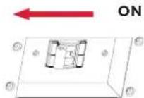
Step 1: Turn off the DC breaker on the EBM.
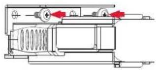
Step 2: Loosen the two screws to remove the battery cable retention bracket of the UPS.
Step 3: Use the output cable of the EBM to connect the EBM to the UPS.
text_image
OFF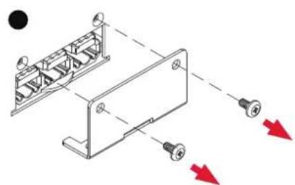
natural_image
Technical diagram of a mechanical assembly with labeled components and directional arrows (no text or symbols)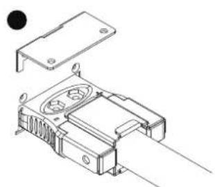
natural_image
Technical line drawing of an electronic component with mounting bracket and internal circuit (no text or symbols)Step 4: Rotate the battery cable retention bracket and tighten the two screws to fix battery cable.
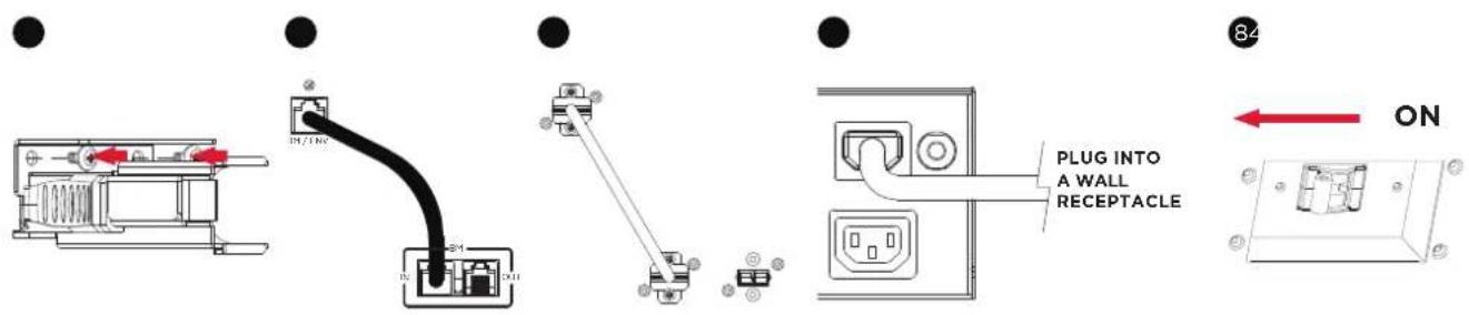
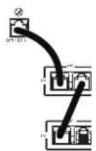
Step 5: Connect the BM/ENV port from UPS rear panel to BM port marked "IN" on the rear panel of the Extended Battery Module using the provided BM cable. Refer to illustration below.
Step 6: Connect the BMP connector from UPS rear panel to left side BMP connector on the rear panel of the Extended Battery Module using the provided BMP cable. Refer to illustration below.
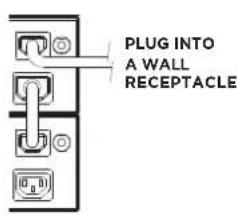
Step 7: Use a NEMA L6-20P to IEC-320-C13 power cord to plug AC input inlet of the battery module into a wall receptacle.
Step 8: Turn on the DC breaker of the EBM.
text_image
IN/IN PLUG INTO A WALL RECEPTACLE ON 84EXTENDED BATTERY MODULE INSTALLATION CONT.
CONNECTION WITH UPS CONT.
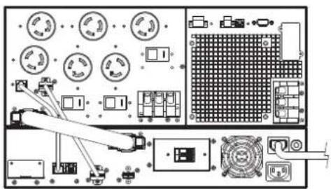
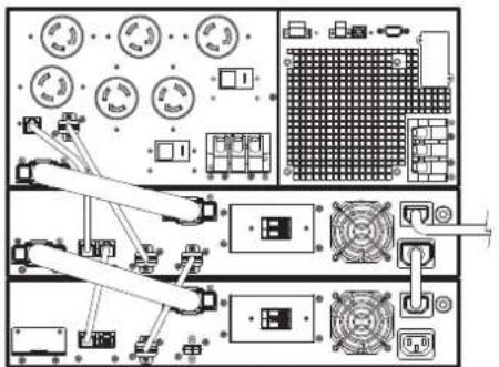
Scenario #2: UPS with multiple Extended Battery Modules (EBMs)
text_image
Technical diagram of an electronic device layout with labeled components and connectionsPlug into a wall receptacle
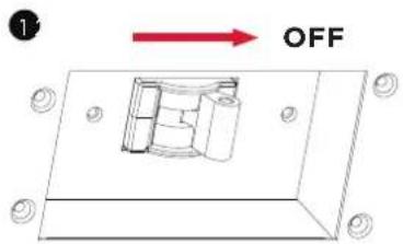
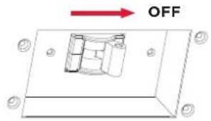
Step 1: Turn off the DC breaker on the EBM.
Step 2: Loosen the two screws to remove the battery cable retention bracket of the UPS.
Step 3: Use the output cable of the EBM to connect the EBM to the UPS.
1
text_image
OFF●

natural_image
Technical diagram of a mechanical assembly with mounting holes and red directional arrows indicating motion (no text or symbols)●

natural_image
Technical line drawing of a mechanical assembly with no visible text or symbolsStep 4: Rotate the battery cable retention bracket and tighten the two screws to fix battery cable.
Step 5: Connect the BM/ENV port from UPS rear panel to BM port marked "IN" on the rear panel of the Extended Battery Module using the provided BM cable, and then connect another BM cable between BM port marked "OUT" and BM port marked "IN" of another Extended Battery Module. Refer to illustration below.
Step 6: Connect the BMP connector from UPS rear panel to left side BMP connector on the rear panel of the Extended Battery Module using the provided PMP cable, and then connect another BMP cable, between BMP connector and right side BMP connector of next Extended Battery Module.Refer to illustration below.
Step 7: Use a NEMA L6-20P to IEC-320-C13 power cord to plug AC input inlet of the battery module into a wall receptacle.
Step 8: Turn on the DC breaker of the EBM.
4
natural_image
Technical line drawing of a mechanical assembly with springs and housing (no text or symbols)5
6
7
text_image
PLUG INTO A WALL RECEPTACLE8
EXTENDED BATTERY MODULE INSTALLATION CONT.
CONNECTION WITH UPS CONT.
Step 9: Turn on the DC breaker of the 2nd EBM.
Step 10: Set the EBM number to the respective setting to match the number of installed units. To do this via the LCD control panel, go to the Configuration Menu, then scroll to the EBM Number setting, select the appropriate number and Save the configuration. This operation can also be done via the RMCARD web UI or via PowerPanel® Business software. Please see their respective User Manual for instructions.
EXTENDED BATTERY MODULES CONFIGURATION
Extended Battery Modules can be configured by the user to display correct estimated battery runtimes.
- Select "Main Menu" and press the "ENTER" button to activate the "Main Menu".
- Press the "UP" and "DOWN" buttons to select the "SET UP" ICON.
- Press the "ENTER" button to enter the "SET UP" function.
- Press the "UP" and "DOWN" buttons to scroll to the "External Batt" option.
- Press the "ENTER" button to enter the "External Batt" option.
- Press the "UP" and "DOWN" buttons to select the "Auto" or "Manual" option.
- (a) Select "Auto" and press the "ENTER" buttons to activate the Auto detect function. (b) Select "Manual" and press the "UP" and "Down" buttons to select the number of EBM installed then press the "ENTER" button to set.
- You may be prompted "Save Change?" to save the selection, if so press the "ENTER" button to save the setting.
- Press the "ESC" button to cancel or return to the previous SET UP menu.
| SET UP ITEMS AVAILABLE SETTINGS | DEFAULT SETTINGS | ||
| External Batt | Auto | If UPS has EQM function, the UPS will Auto detect the external batt number. | None |
| Manual | = [0] [1] [2] [3] [4] [5] [6] [7] [8] [9] [10]Sets the actual EBM (extended battery modules) number to get the correct estimated runtime. | 0 | |
HARDWARE INSTALLATION
CyberPower Extended Battery Module (EBM) can be installed in a rackmount or vertical/tower orientation. This versatility is especially important to growing organizations with changing needs that value having the option to position an EBM on the floor or in a rackmount system. Note that the included rack mounting hardware is only compatible with square hole racks. Please follow the instructions below for the respective mounting methods.
RACKMOUNT INSTALLATION FOR 4-POST RACK

Caution: Important Instructions
To prevent the risk of fire or electric shock, only use the supplied hardware to attach the mounting brackets.
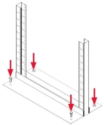
Step 1: Remove the dust covers
Remove ten dust covers from the screw holes as shown below.
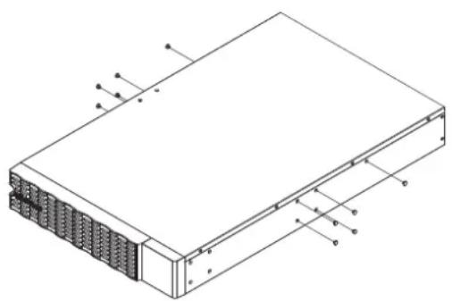
Step 2: Rackmount ear & hanging bracket installation
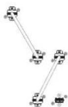
Attach two rackmount ears to the EBM using eight black M5X7L flat head screws and tighten two hanging brackets using six silver M5X6L pan head screws.
1
natural_image
Isometric technical diagram of a server rack with labeled components (no text or symbols present)2

natural_image
Technical line drawing of a server rack with mounting brackets and ventilation grilles (no text or symbols)Step 3: Rackmount rail Installation
The mounting depth of the included rackmount rails can adjust from 20.5 in to 36 in (52 cm to 91.5 cm). Select the proper holes in the rack for positioning the EBM in the rack. The EBM takes up 2 rack units: rack hole positions 1 through 6.
Position the guide screws on the back of the rackmount rails into the rear rack square holes to temporarily support the rails in place.
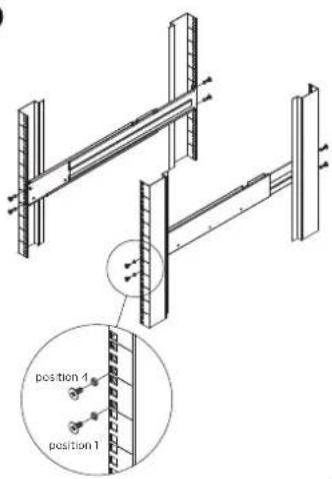
Step 4: Adjust rackmount rails to fit your rack
Adjust the rail depth to match your rack depth. Attach each rackmount rail to your rack with two black M5X8L pan head screws and two plastic washers at the front of the rack (square holes 1 and 4 as shown below). Secure each rail to the rear of the rack with two black M5X8L pan head screws and two plastic washers
HARDWARE INSTALLATION CONT.
RACKMOUNT INSTALLATION FOR 4-POST RACK CONT.
3
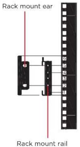
text_image
Rack mount ear 0 5 4 3 2 1 Rack mount rail4
text_image
position 1 position 1
text_image
5 position 5 position 2 position 4 position 1
natural_image
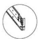
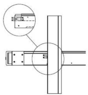
Technical line drawing of a structural frame assembly with an inset magnified detail (no text or symbols)Step 5: Place and secure the EBM on the rails
Slide the hanging brackets on the EBM on to the rails mounted in the rack with the front of the unit facing toward you. Secure the EBM to your rack with four black M5X8L pan head screws at the front of the rack (square holes 2 and 5 as shown above).
NOTE: To slide the EBM out from the rack
The EBM will be secured by a safety locking mechanism midway of pulling it out of the rack. Use both hands to hold the EBM and press the safety locking tab to pull the EBM out.
natural_image
Technical line drawing of a mechanical assembly with a circular inset showing a component detail (no text or symbols)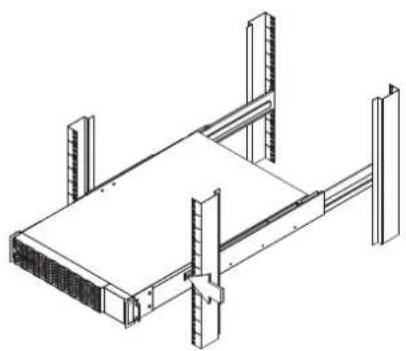
natural_image
Isometric line drawing of a structural frame with vertical supports and horizontal beams (no text or symbols)
natural_image
Pure technical line drawing of a rectangular frame with corner brackets (no text or symbols)RACKMOUNT INSTALLATION FOR 2-POST RACK

CAUTION! Due to the weight of this unit, it is strongly recommended to install it at the bottom of the rack.
CAUTION! Prior to installing the unit, remove internal batteries to reduce the weight of the unit. Refer to the battery replacement section in this user manual for instructions.
CAUTION! It is strongly recommend having 2-3 people assist during the installation process.
CAUTION! It is strongly recommended that the 2 post rack be bolted to the floor prior to the installation of the EBM.
text_image
Diagram showing measurement setup with ruler and two vertical supports, each marked with red downward arrows indicating measurement points.Step 1: Remove side dust covers
Remove seven dust covers from screw holes as shown below.
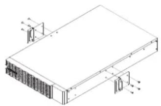
Step 2: Rackmount ears installation
Attach the included rackmount ears to the center holes on the sides of the EBM using eight black M5X7L screws as shown below.
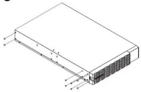
Step 3: Secure the EBM to the rack
Secure the EBM to your rack with four black M5X8L screws at the front of the rack (square holes 2 and 5 as shown below)
1

natural_image
Isometric line drawing of a server rack with labeled components (no text or symbols)2
natural_image
Isometric line drawing of a rectangular electronic device with internal components and mounting brackets (no text or symbols)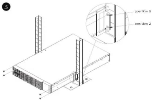
text_image
3 position 5 position 2 a bHARDWARE INSTALLATION CONT.
VERTICAL/TOWER INSTALLATION
Step 1: Adhere rubber pads
Adhere four circular rubber pads to the left hand side of the extended battery module. This will become the bottom side. Insert the dust covers into the open screw holes on bottom.
Step 2: Attach the base stands and attach the dust covers
Stand the EBM on its side with the rubber pads facing down. If installing the EBM together with a UPS, remove the four dust covers first and secure the tie plate between the UPS and the EBM using four silver M5X6L pan head screws. Adhere four circular rubber pads to each tower stand and screw on to the EBM and UPS for added stability a shown below. Insert the dust covers into the open screw holes on top.
1
natural_image
Isometric line drawing of a rectangular electronic device with internal components and labeled terminals (no text or symbols present)2

text_image
Technical diagram of a heat exchanger or cooling unit with labeled components and a red circular arrow indicating rotation direction.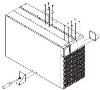
natural_image
Isometric technical diagram of a mechanical or electrical component with mounting holes and a clamping tool (no text or symbols)MAINTENANCE
Storage
To store your EBM for an extended period of time, cover and store it with the battery fully charged. Recharge the battery every three months to ensure battery life.
Battery Replacement
Please read and follow the Safety Instructions before servicing the battery. Battery replacement should be performed by trained personnel who are familiar with the procedures and safety precautions. Make a note of the Replacement Battery part number.
Safety Precautions

Warning: High voltage - Risk of Electric Shock
Only use replacement batteries that are certified by Cyber Power Systems. Use of incorrect battery type is an electrical hazard that could lead to explosion, fire, electric shock, or short circuit.
Batteries contain an electrical charge that can cause severe burns. Before servicing batteries, please remove any conductive materials such as jewelry, chains, wrist watches, and rings.
Do not open or mutilate the batteries. Electrolyte fluid is harmful to the skin/eyes and may be toxic.
To avoid electric shock, turn off and unplug the EBM from the wall receptacle before servicing the battery.
Only use tools with insulated handles. Do not lay tools or metal parts on top of the EBM or battery terminals.
Replacement Batteries
Please refer to the front side of the EBM for the model number of the correct replacement batteries. For battery procurement, go to www.CyberPowerSystems.com, or contact your local dealer.
When the UPS LCD displays Service Battery, use PowerPanel® Business software or log on to the RMCARD to perform a runtime calibration to verify battery capacity is sufficient and acceptable.
MAINTENANCE CONT.
Battery Disposal

Do Not Discard
Batteries are considered hazardous waste and must be disposed of properly. Contact your local government for more information about proper disposal and recycling of batteries. Do not dispose of batteries in fire.
Cyber Power Systems encourages environmentally sound methods for disposal and recycling of its UPS products.
Please dispose and/or recycle your UPS and batteries in accordance with local regulations.
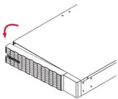
BATTERY REPLACEMENT CONT.
Step 1: Remove the front panel.
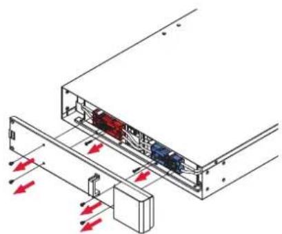
Step 2: Unscrew and open the battery access door. Loosen the two screws on the battery connectors.
Step 3: Disconnect the battery connector and then disconnect battery management module connector.
1
natural_image
Technical diagram of a mechanical assembly with a red arrow indicating rotation (no text or symbols present)2
natural_image
Technical diagram of an internal device with red arrows indicating directional flow or movement, no text or symbols present.3
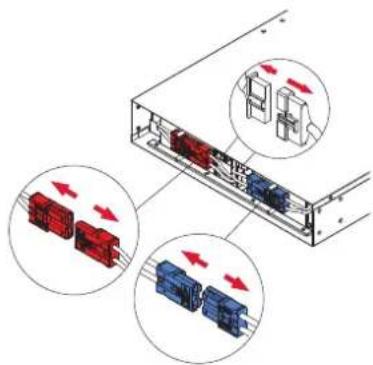
text_image
Diagram showing three red and blue connector blocks with directional arrows indicating flow or movement, likely illustrating a system or process.MAINTENANCE CONT.
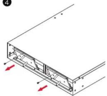
BATTERY REPLACEMENT CONT.
Step 4: Unscrew the battery retention bracket and then open it
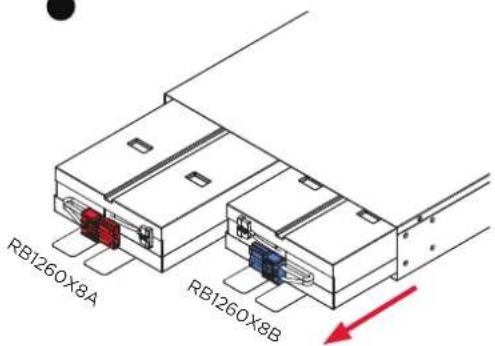
Step 5: Pull the battery trays out slowly and then put the new battery trays into the compartment.
Step 6 : Assemble battery retention cover. Connect battery management module connector and then connect the battery connector. Ensure that they are seated properly (connector will click into place). Tighten the battery access door.
Step 7: Install the front panels. Execute a battery test via the LCD control panel. To do this go to the Main Menu and select the Diagnostics Icon, then select Battery Test and Activate. After Battery test, go back to the Main Menu then select the Set UP icon, then select Batt Install Date to set the battery installation date. This operation can also be done via PowerPanel® Business or the RMCARD web interface. Please see their respective User Manuals for detailed instructions.
4
natural_image
Technical diagram of a mechanical assembly with red arrows indicating direction (no text or symbols)●
text_image
RB1260X8A RB1260X8B●

natural_image
Technical diagram of a mechanical assembly with red arrows indicating force or movement (no text or symbols present)
text_image
Diagram showing three labeled electrical connectors with red and blue blocks, illustrating a circuit or connection mechanism.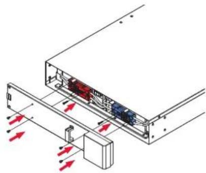
natural_image
Technical diagram of an electronic device showing internal components and directional arrows (no text or symbols)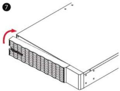
natural_image
Diagram of a mechanical assembly with a red arrow indicating rotation, showing no text or symbols.TECHNICAL SPECIFICATIONS
| MODELS BP192VL2U01 | |
| CONFIGURATION | |
| AC Input Voltage 200-240 V | |
| DC Output Voltage 192 Vdc | |
| DC Output Current 60 A | |
| PHYSICAL | |
| Dimensions L x W x H = 28.3 X 17.05 x 3.4 in (72 x 43.3 x 8.65 cm) | |
| Net Weight 101.4 lb (46Kg) | |
| BATTERY | |
| Specifications (16) 12 V/6 Ah | |
| Replacement Battery Cartridge RB1260X8A (1) (Left) + RB1260X8B (1) (Right) | |
| Recharge Time 0-90% (Typical) 4 hours | |
| Hot-Swappable Yes | |
| Built-in Charger Yes | |
| ENVIRONMENT | |
| Operating Temperature 32 °F to 104 °F (0 °C to 40 °C) | |
| Operating Relative Humidity 0 to 90% Non-Condensing | |
| SAFETY | |
| Conformance Approvals CE, UL1778, FCC part 15 Class A | |
| RoHS RoHS Compliant | |
TROUBLESHOOTING
| PROBLEM POSSIBLE CAUSE SOLUTION | ||
| WARNING | ||
| BAT Disconnected | No battery power is being detected by the UPS. | Check the battery connector and the battery breaker. |
| Battery Failure UPS has failed a Battery Test. | Check the battery connector and the battery breaker.Contact technical support to replace battery if under the warranty period.. | |
| Replace Battery | Battery will soon need to be replaced due to insufficient runtime. | Install new batteries, execute battery test, and reset the replace battery date. |
| Service Battery | The Battery Replacement Date has reached the recommended 3 year maintenance period. | Perform a runtime calibration to verify battery capacity is sufficient and acceptable.If batteries have been recently replaced, then reset the Battery Replacement Date using PowerPanel® Business software, RMCARD web interface or through the LCD control panel on the UPS (See LCD Configuration Settings). |
| FAULT | ||
| Over Charge Battery is overcharged. | Remove the battery connector and check charger voltage.Contact CyberPower for repair. | |
| Charger Failure Charger has failed. | ||
PRODUCT REGISTRATION
CyberPower requests that you complete and return the Warranty Registration Card enclosed with the Product or register the Product at its website (www.cyberpowersystems.com/registration) to establish that you are the Initial Customer of the Product, and therefore entitled coverage under the Limited Warranty and the Connected Equipment Guarantee. (Registration is not required for coverage, but note: if you do not register your purchase, you will be required to provide proof of purchase.)
LIMITED WARRANTY
Read the following terms and conditions carefully before using the CyberPower BP192VL2U01. By using the Product you consent to be bound by and become a party to the terms and conditions of this Limited Warranty (together referred to as the "Warranty"). If you do not agree to the terms and conditions of this Warranty, you should return the Product for a full refund prior to using it.
Who is Providing this Warranty?
CyberPower Systems (USA), Inc. ("CyberPower") provides this Limited Warranty.
What Does This Warranty Cover?
This warranty covers defects in materials and workmanship in the Product under normal use and conditions.
What is the Period of Coverage?
This warranty covers the Product for three years.
Who Is Covered?
This warranty only covers the original purchaser. Coverage ends if you sell or otherwise transfer the Product.
How Do You Get Warranty Service?
- Before contacting CyberPower, identify Your Product model number, and the Purchase Date.
- Email us at tech@cpsww.com or Call us at (877) 297-6937.
- If your product requires warranty service you must provide a copy of your dated purchase receipt or invoice.
LIMITED WARRANTY CONT.
How Do You Open A Warranty Claim?
- Call us at (877) 297-6937 or write to us at Cyber Power Systems (USA), Inc., 4241 12th Ave. E., STE 400, Shakopee, MN 55379, or send us an e-mail message to claims@cpsww.com for instructions, within 10 days of the occurrence.
- When you contact CyberPower, identify the Product, the Purchase Date, and Request a Claim Number.
- You must provide a dated purchase receipt (or other proof of the original purchase) for the Cyber Power unit.
- Pack and ship the product to CyberPower and all claim forms that CyberPower provides to you. Show the Claim Number on the shipping label or include it with the product. You must prepay all shipping costs, you are responsible for packaging and shipment, and you must pay the cost of the repair estimate.
How Long Do I Have To Make A Claim?
All claims must be made within ten days of the occurrence.
What Will We Do To Correct Problems?
CyberPower will inspect and examine the Product.
If the Product is defective in material or workmanship, CyberPower will repair or replace it at CyberPower's expense, or, if CyberPower is unable to or decides not to repair or replace the Product (if defective) within a reasonable time, CyberPower will refund to you the full purchase price you paid for the Product (purchase receipt showing price paid is required).
Who Pays For Shipping?
We pay when we send items to you; you pay when you send items to us.
LIMITED WARRANTY CONT.
What Are Some Examples Of What This Warranty Does Not Cover?
- This Warranty does not cover any software that was damaged or needs to be replaced due to the failure of the Product or any data that is lost as a result of the failure or the restoration of data or records, or the reinstallation of software.
- This Warranty does not cover or apply to: misuse, modification, operation or storage outside environmental limits of the Product or the equipment connected to it, nor for damage while in transit or in storage, nor if there has been improper operation or maintenance, or use with items not designed or intended for use with the Product, such as laser printers, appliances, aquariums, medical or life support devices, etc.
What Other Limitations Apply?
The sole and exclusive remedies of the Initial Customer are those provided by this Warranty.
- This Warranty does not apply unless the Product and the equipment that was connected to it were connected to properly wired and grounded outlets (including compliance with electrical and safety codes of the most current electrical code), without the use of any adapters or other connectors.
- The Product must have been plugged directly into the power source and the equipment connected to the Product must be directly connected to the Product and not "daisy-chained" together in serial fashion with any extension cords, another Product or device similar to the Product, surge suppressor, or power tap. Any such installation voids the Limited Warranty.
-
The Product must have been used properly in a suitable and proper environment and in conformance with any license, instruction manual, or warnings provided with the Product and the equipment connected to it.
-
The Product must have been used at all times within the limitations on the Product's VA capacity.
The Product was designed to eliminate disrupting and damaging effects of momentary (less than 1ms) voltage spikes or impulses from lightning or other power transients. If it can be shown that a voltage spike lasting longer than 1ms has occurred, the occurrence will be deemed outside the rated capabilities of the Product and the Limited Warranty is void. CyberPower Does Not Cover or Undertake Any Liability in Any Event for Any of the Following:
- Loss of or damage to data, records, or software or the restoration of data or records, or the reinstallation of software.
LIMITED WARRANTY CONT.
What Other Limitations Apply? Cont.
- Damage from causes other than AC Power Line Transients, spikes, or surges on properly installed, grounded and code-compliant 120 volt power lines in the United States and Canada; transients, surges or spikes on standard telephone land lines, PBX telephone equipment lines or Base 10T Ethernetlines, when properly installed and connected. (This exclusion applies, for example, to fluctuations in data transmission or reception, by CATV or RF transmission or fluctuations, or by transients in such transmission.)
- Damage from any circumstance described as excluded above with respect to the Product.
- Damages from fire, flood, wind, rain, rising water, leakage or breakage of plumbing, abuse, misuse or alteration of the product.
- CyberPower excludes any liability for personal injury under the Limited Warranty. CyberPower excludes any liability for direct, indirect, special, incidental or consequential damages, whether for damage to or loss of property [EXCEPT FOR (AND ONLY FOR) the specific limited agreement of CyberPower to provide certain warranty benefits, loss of profits, business interruption, or loss of information or data. NOTE: Some States or Provinces do not allow the exclusion or limitation of incidental or consequential damages, so the above limitation may not apply to you.
- The Product is not for use in high-risk activities or with aquariums. The Product is not designed or intended for use in hazardous environments requiring fail-safe performance, or for use in any circumstance in which the failure of the Product could lead directly to death, personal injury, or severe physical or property damage, or that would affect operation or safety of any medical or life support device (collectively, "High Risk Activities"). CyberPower expressly disclaims any express or implied warranty of fitness for High Risk Activities or with aquariums. CyberPower does not authorize use of any Product in any High Risk Activities or with Aquariums. ANY SUCH USE IS IMPROPER AND IS A MISUSE OF THE PRODUCT.
Where Can I Get More Information?
The application of the United Nations Convention of Contracts for the International Sale of Goods is expressly excluded.
CyberPower is the warrantor under this Limited Warranty.
For further information please feel free to contact CyberPower at
Cyber Power Systems (USA), Inc. | 4241 12th Ave E., STE 400, Shakopee, MN 55379
(877) 297-6937 | claims@cpsww.com
CONFORMANCE APPROVAL

FCC NOTICE
This device complies with part 15 of the FCC Rules. Operation is subject to the following two conditions: (1) This device may not cause harmful interference, and (2) this device must accept any interference that may cause undesired operation.
WARNING!! This equipment has been tested and found to comply with the limits for a Class A digital device, pursuant to part 15 of the FCC Rules. These limits are designed to provide reasonable protection against harmful interference when the equipment is operated in a commercial environment. This equipment generates, uses, and can radiate radio frequency energy and, if not installed and used in accordance with the instruction manual, may cause harmful interference to radio communications. Operation of this equipment in a residential area is likely to cause harmful interference in which case the user will be required to correct the interference at his own expense. Shielded signal cables must be used with this product to ensure compliance with the Class A FCC limits.
The Class A digital apparatus meets all requirements of the Canadian Interference-Causing Equipment Regulation.
This document is believed to be accurate, but CyberPower reserves the right to change or correct the contents and does not assume any responsibility for omissions or errors.
Need Additional Help?
See Operation and Installation Manual provided and also available to download at www.CyberPowerSystems.com Still Need Help? Please contact our Tech Support department with installation, troubleshooting, or general product questions.
CyberPower Technical Support
Phone: 1-877-297-6937
Email: tech@cpsww.com
Web: www.CyberPowerSystems.com
Address: 4241 12th Avenue E., Suite 400, Shakopee, MN 55379, USA
Hours of Operation:
Monday - Friday, 7:00am - 6:00pm (CST)
CyberPower
Cyber Power Systems, Inc. | www.CyberPowerSystems.com
For USA and Canada | 4241 12th Ave East, Suite 400, Shakopee, MN 55379 | Toll-free: 877.297.6937
For all other regions | Please visit our website for local contact information.
Copyright © 2022 Cyber Power Systems, Inc. All rights reserved.