
WP-211X - Switch Kramer - Free user manual and instructions
Find the device manual for free WP-211X Kramer in PDF.

| Product Type | 4K HDR HDMI Auto Switcher Wall Plate |
| Model | WP-211X |
| Brand | Kramer |
| Inputs | 2 x HDMI (Female) |
| Output | 1 x HDMI (Female) |
| Audio Output | 1 x 3-pin Terminal Block (Unbalanced Analog) |
| Video Resolution | Up to 4K@60Hz (4:4:4) HDR |
| Switching Modes | Manual (button) or Auto (priority or last connected) |
| EDID Management | Locked or Pass-through via DIP-switch |
| Power Supply | 12V DC, 2-pin Terminal Block (adapter included) |
| Power Consumption | 5W (typical) |
| Dimensions (Wall Plate) | US: 1 Gang (4.13 x 2.76 in / 105 x 70 mm); EU: 68mm cut-out; UK: 75x75mm |
| Weight | 0.3 kg (0.66 lbs) approx. |
| Firmware Upgrade | Via Mini USB (PROG port) |
| Grounding | Ring tongue terminal (optional) |
| Compliance | HDMI 2.0, HDCP 2.2 |
| Operating Temperature | 0° to 40°C (32° to 104°F) |
| Storage Temperature | -20° to 60°C (-4° to 140°F) |
| Humidity | 10% to 90% RH (non-condensing) |
| Maintenance | Clean with a dry, soft cloth; no liquids or solvents |
| Safety | Use only supplied power cord; no user-serviceable parts; replace fuses per rating |
| Warranty | Limited warranty (check Kramer support) |
| Included Accessories | Power adapter, frame/faceplate, quick start guide, installation accessories |
Frequently Asked Questions - WP-211X Kramer
User questions about WP-211X Kramer
0 question about this device. Answer the ones you know or ask your own.
Ask a new question about this device
Download the instructions for your Switch in PDF format for free! Find your manual WP-211X - Kramer and take your electronic device back in hand. On this page are published all the documents necessary for the use of your device. WP-211X by Kramer.
USER MANUAL WP-211X Kramer
Scan for full manual
WP-211X Quick Start Guide
This guide helps you install and use your WP-211X for the first time.
Go to www.kramerav.com/downloads/WP-211X to download the latest user manual and check if firmware upgrades are available.
Step 1: Check what's in the box
WP-211X 4K HDR HDMI Auto Switcher Wall Plate
√ Frame (or frame set) and faceplate
1 Quick start guide
1 Power adapter and cord
Installation accessories
Step 2: Get to know your WP-211X
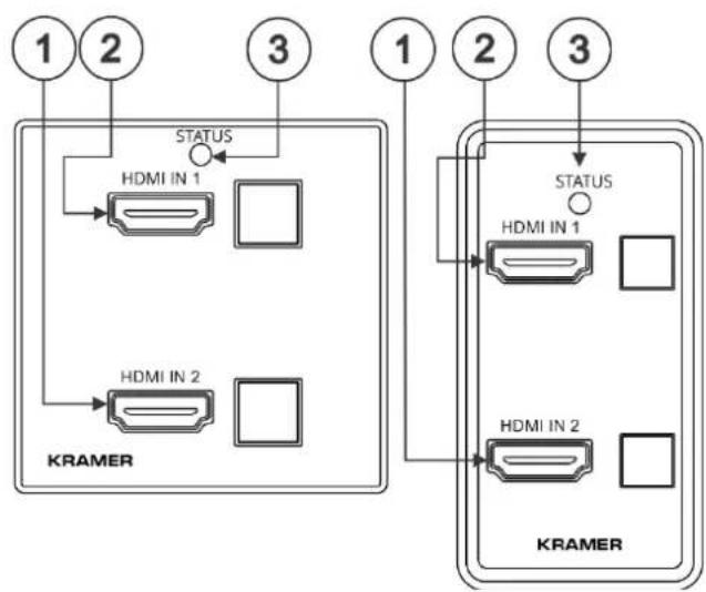
EU/UK Version
Front
US-D Version
Front
US-D/EU/UK Version
Front, faceplate removed
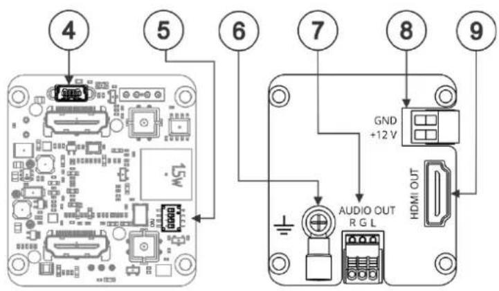
US-D/EU/UK Version
Rear
flowchart
graph TD
    subgraph_Left_KRAMER["1: HDMI IN 1"]
        A["HDMI IN 1"] --> B["HDMI IN 2"]
        C["HDMI IN 2"] --> D["HDMI IN 2"]
        E["1"] --> F["STATUS"]
        G["2"] --> H["STATUS"]
        I["3"] --> J["STATUS"]
    end
    subgraph_Right_KRAMER["1: HDMI IN 1"]
        K["HDMI IN 1"] --> L["HDMI IN 2"]
        M["HDMI IN 2"] --> N["HDMI IN 2"]
        O["1"] --> P["STATUS"]
        Q["2"] --> R["STATUS"]
        S["3"] --> T["STATUS"]
| # | Feature | Function |
| 1 | HDMI IN 2 Connector | Connects to an HDMI source. |
| HDMI IN 2 Button | Press to select the HDMI 2 input (button lights orange). | |
| 2 | HDMI IN 1 Connector | Connects to an HDMI source. |
| HDMI IN 1 Button | Press to select the HDMI 1 input (button lights orange). | |
| 3 | STATUS LED | Lights green when the device is powered and blue when an HDMI output is connected. |
| 4 | PROG Mini USB Connector | Connect to upgrade the firmware. |
| 5 | SETUP 4-way DIP-Switches | Set the operation DIP-switches (see Setting the DIP-Switches). |
| 6 | Ring Tongue Terminal Grounding Screw | Connect to grounding wire (optional). |
| 7 | AUDIO OUT 3-pin Terminal Block Connector | Connect to an unbalanced analog audio acceptor. |
| 8 | Power Supply 2-pin Terminal Block Connector | Connect to the power supply. Connect GND to GND, +12V to +12V. |
| 9 | HDMI OUT Connector | Connect to an HDMI acceptor. |
The terms HDMI, HDMI High-Definition Multimedia Interface, and the HDMI Logo are trademarks or registered trademarks of HDMI Licensing Administrator, Inc.
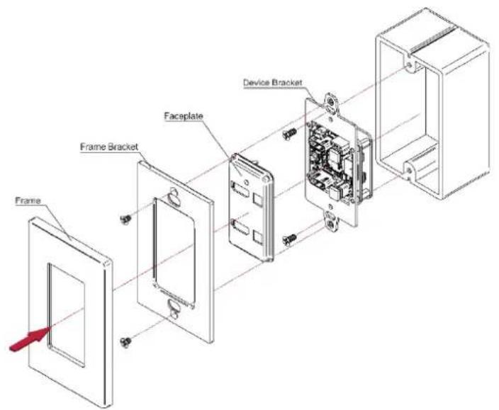
Step 3: Install the WP-211X
Insert the device into the in-wall box (note that first you need to connect the HDBT cable and power) and connect the parts as shown in the illustrations below:
US-D Version
EU/UK Version
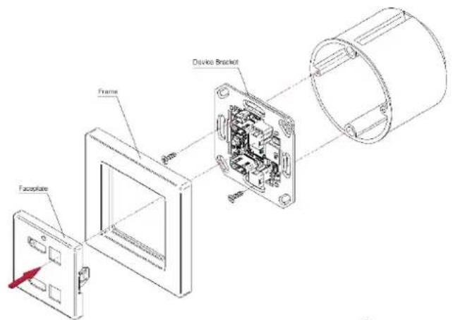
For BS EN 60670-1 attach the spacers before inserting the device.
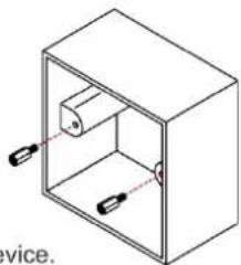
natural_image
Isometric line drawing of a rectangular box with internal components and two hanging weights (no text or symbols)
DECORA® design or similar frames are included in US-D models. DECORA® is a registered trademark of Leviton Manufacturing Co., Inc.
We recommend that you use any of the following standard 1 Gang in-wall junction boxes (or their equivalent):
• US-D: 1 Gang US electrical junction boxes.
- EU: 1 Gang in-wall junction box, with a cut-hole diameter of 68mm and depth that can fit in both the device and the connected cables (DIN 49073).
- UK: 1 Gang in-wall junction box, 75x75mm (W, H) and depth that can fit in both the device and the connected cables (BS 4662 or BS EN 60670-1 used with supplied spacers and screws).
Step 4: Connect the inputs and outputs
Always switch OFF the power on each device before connecting it to your WP-211X. For best results, we recommend that you always use Kramer high-performance cables to connect AV equipment to the WP-211X.

flowchart
graph TD
    A["Blu-ray Player"] --> B["HDMI"]
    C["Set Top Box"] --> D["HDMI"]
    E["Active Speakers"] --> F["Audio"]
    G["Display"] --> H["HDMI"]
    I["KRAMER"] --> J["HDMI IN 1"]
    I --> K["HDMI IN 2"]
    style A fill:#cce5ff,stroke:#333
    style C fill:#cce5ff,stroke:#333
    style E fill:#cce5ff,stroke:#333
    style G fill:#cce5ff,stroke:#333
    style I fill:#cce5ff,stroke:#333
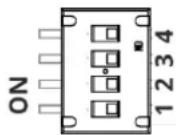
Setting the DIP-Switches
DIP-switches 1, 2 and 3 are set to ON by default and DIP-switch 4 is always set to OFF.
DIP-switch changes take effect immediately.
| # | Feature | Dip-Switch Settings |
| 1 | Switching Mode | OFF – Manual mode.ON –Auto-switching mode. |
| 2 | Auto-switching Mode | OFF – Priority switching mode: the device switches the source with the highest priority to the output.ON – Last connected switching mode: the last detected active source is auto-switched to the output. |
| 3 | EDID lock | Off – EDID Locked.On – EDID parameters are passed-through. |
| 4 | Reserved for Factory Use | It is mandatory to keep set to OFF. |
For optimum range and performance use the recommended Kramer cables available at www.kramerav.com/product/WP-211X
Grounding the WP-211X (Optional)
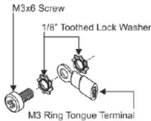
- Connect the ring tongue terminal to the building grounding point wire (a green-yellow, AWG#18 (0.82mm ^4 ) wire, crimped with a proper hand-tool is recommended).
- Insert the M3x6 screw through the toothed lock washers and the tongue terminal in the order shown above.
- Insert the M3x6 screw (with the two toothed lock washers and ring tongue terminal) into the grounding screw hole and tighten the screw.
Step 5: Connect the power
Connect the 12V power adapter to the device and plug the power supply into the mains electricity.
Safety Instructions

Caution:
- For products with relay terminals and GPIO ports, please refer to the permitted rating for an external connection, located next to the terminal or in the User Manual.
- There are no operator serviceable parts inside the unit.
Warning:
- Use only the power cord that is supplied with the unit.
- Disconnect the power and unplug the unit from the wall before installing.
- Do not open the unit. High voltages can cause electrical shock! Servicing by qualified personnel only.
• To ensure continuous risk protection, replace fuses only according to the rating specified on the product label which located on the bottom of the unit.


Brand : Kramer
Model : WP-211X
Category : Switch