ICR-4401S - Router Advantech - Free user manual and instructions
Find the device manual for free ICR-4401S Advantech in PDF.

User questions about ICR-4401S Advantech
0 question about this device. Answer the ones you know or ask your own.
Ask a new question about this device
Download the instructions for your Router in PDF format for free! Find your manual ICR-4401S - Advantech and take your electronic device back in hand. On this page are published all the documents necessary for the use of your device. ICR-4401S by Advantech.
USER MANUAL ICR-4401S Advantech
LAN Industrial Router
ICR-4401
USER MANUAL
text_image
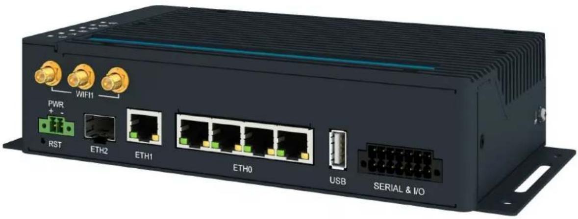
WIFI PWR + - RST ETH2 ETH1 ETH0 USB SERIAL & I/O© 2023 Advantech Czech s.r.o. No part of this publication may be reproduced or transmitted in any form or by any means, electronic or mechanical, including photography, recording, or any information storage and retrieval system without written consent. Information in this manual is subject to change without notice, and does not represent a commitment on the part of Advantech.
Advantech Czech s.r.o. shall not be liable for incidental or consequential damages resulting from the furnishing, performance, or use of this manual.
All brand names used in this manual are the registered trademarks of their respective owners. The use of trademarks or other designations in this publication is for reference purposes only and does not constitute an endorsement by the trademark holder.
Used symbols

Danger – Information regarding user safety or potential damage to the router.

Attention - Problems that can arise in specific situations.

Information, notice – Useful tips or information of special interest.

text_image
CE UK CA
TÜVRheinland ^®
COTI
ISO 9001
Contents
1 Product Overview 2
1.1 Product Introduction 2
1.2 Hardware Overview 3
1.3 Order Codes 5
1.4 Product Revisions 5
1.5 Package Contents 6
1.6 Product Dimensions 7
1.7 Mounting Recommendations 9
1.8 Wall Mounting 10
1.9 DIN Rail Mounting 11
1.10 Product Label 12
2 Hardware Functionality 13
2.1 Antennas Interfaces 13
2.2 Ethernet Interfaces 13
2.3 Power over Ethernet (PoE) PSE 14
2.4 SFP Cage 16
2.5 Power Supply 17
2.6 Low Power Mode 18
2.7 I/O Port Interfaces 19
2.8 Serial Interfaces 20
2.9 USB Port 21
2.10 MicroSD Card Reader 22
2.11 LED Status Indication 24
2.12 Reset Functions 25
3 First Use 26
3.1 Accessories Connection 26
3.2 Router Configuration 26
4 Technical Parameters 28
4.1 Basic Parameters 28
4.2 Standards and Regulations 29
4.3 Type Tests and Environmental Conditions 30
4.4 Parameters of WiFi 31
4.5 Parameters of I/O Ports 32
4.6 Parameters of Serial Interfaces 32
4.7 Parameters of PoE 33
4.8 System Configuration 33
Appendix A: Troubleshooting 34
Appendix B: Customer Support 36
Appendix C: Regulatory & Safety Information 37
Appendix D: Related Documents 39
List of Figures
1 Hardware Overview of the Router 3
2 Router Dimensions – Front, Top and Right view with Wall Mounting holder . . . 7
3 Router Dimensions – Front, Top and Right view with DIN holder ..... 8
4 Rotated Wall Mounting Clips 10
5 Default Position of the DIN Rail Clips 11
6 Removing Router from the DIN Rail 11
7 Label Example 12
8 Ethernet Connector Pinout of RJ45 Socket 13
9 PoE PSE Funcional Scheme 14
10 SFP Module Installation 16
11 Power Connector Pinout 17
12 Position of the Grounding Screw 18
13 I/O Connector Pinout 19
14 Functional Scheme of the Binary Interface 19
15 Serial Connector Pinout 20
16 USB Connector Pinout 21
17 MicroSD Card Insertion 22
18 Resetting the Router 25
19 Router's Web Interface 27
List of Tables
1 Hardware Overview of the Router 4
2 Order Codes Overview 5
3 HW Revisions History 5
4 Contents of Package 6
5 Ethernet Connector Pinout Description of RJ45 Socket 13
6 PoE PSE Parameters 15
7 Tested SFP Modules 16
8 Power connector pinout 17
9 Connection of I/O Ports 19
10 Connection of RS232 20
11 Connection of CAN Bus 20
12 Connection of RS485 20
13 USB Connector Pinout 21
14 Technical Specifications of MicroSD Card 22
15 LED Status Indication 24
16 Basic Parameters 28
17 Standards and Regulations 29
18 Type Tests and Environmental Conditions 30
19 Technical Parameters of WiFi 31
20 Electrical Characteristics of Binary Inputs 32
21 Parameters of Serial Interfaces 32
22 System Configuration 33
1. Product Overview
1.1 Product Introduction
The ICR-4401 is a LAN Router & Powerful Edge Computing Gateway focused on the global market.
This router is an ideal solution for demanding IoT applications such as industrial routers and gateways, digital signage, industrial computers, and tablets, etc.
The router, assembled in a robust metal box, is equipped with five 1Gb Ethernet ports, one SFP cage together with interfaces of RS232, RS485, CAN bus, two binary inputs and two binary outputs. A microSD card can be inserted under this cover as well. The designated router models can be equipped with a WiFi module with 3x3 MIMO antennas.
Configuration of the router may be done via a password-protected Web interface. Web interface provides detailed statistics about the router's activities, signal strength, detailed system log etc. The router supports VPN tunnels using IPSec (), OpenVPN, GRE, L2TP or PPTP to make sure safe communication. IPv6 Dual Stack, DHCP, NAT, NAT-T, DynDNS, DNS proxy, VLAN, QoS, NTP, VRRP, port forwarding, primary connection backup and many other functions are supported.
The router supports the Low Power Mode and hardware watchdog, which monitors the router status and performs an automatic restart if required.
The user may insert Linux scripts which are started on various actions. It is possible to create up to four different configurations for the same router. These configurations can be switched when necessary via Web interface or binary input status.
The router can automatically upgrade its configuration and firmware from your central server. WebAccess/DMP and WebAccess/VPN remote device management platforms are supported as well.
Examples of possible applications
- mobile office
- security system
- remote monitoring
• vending and dispatcher machines
1.2 Hardware Overview
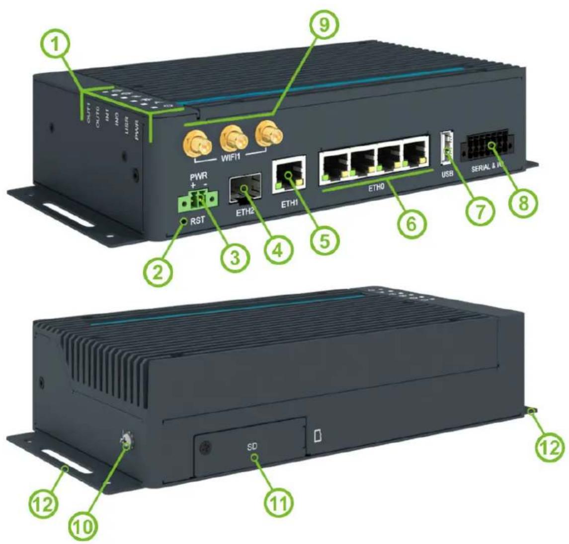
The router case preview is shown in Figure 1. A short description of hardware parts of the router is listed in Table 1, including the links to the chapters with a detailed description.
text_image
1 OUT1 OUT0 INT INT3 USB PWR WIFI 9 PWR + - RST ETH2 ETH1 ETH0 USB SERIAL & IN 2 3 4 5 6 7 8 12 12 10 SD 11 12Figure 1: Hardware Overview of the Router
| # Item/Caption Type | Description | ||
| 1 | LEDs | — | Status LED indication; see Chapter 2.11. |
| 2 | RST | — | Button to reboot the router or to restore the default configuration; see Chapter 2.12. |
| 3 PWR 2-pin | terminal | Power supply socket; see Chapter 2.5. | |
| 4 ETH2 SFP cage SFP | cage socket for modules with speed up to 10 Gbps; see Chapter 2.4. | ||
| 5 | ETH1 | RJ45 | 1 Gb Ethernet connection for the second LAN; see Chap-ter 2.2. |
| 6 | ETH0 | RJ45 | 1 Gb Ethernet switched connection (with four ports) for the first LAN; see Chapter 2.2. |
| 7 | USB | USB-A | USB 2.0 host port; see Chapter 2.9. |
| 8 SERIAL & I/O | 14-pin terminal | RS232, RS485, CAN bus, binary input, and binary output interfaces. See Chapter 2.7 for more information, Chap-ter 4.5 for I/O parameters, and Chapter 4.6 for serial inter-face parameters. | |
| 9 | WIFI1 | R-SMA | Connectors for the WiFi antennas. See Chapter 2.1 for more information and Chapter 4.4 for WiFi parameters. |
| 10 Grounding screw | M3 | Pay attention to proper grounding; see Chapter 2.5. | |
| 11 | microSD slot | microSD | MicroSD card slot; see Chapter 2.10. |
| 12 | Wall clips | — | Wall mounting clips, included as standard accessories; see Chapter 1.8. |
Table 1: Hardware Overview of the Router
1.3 Order Codes
Order codes overview is shown in the table below.
| Order code Configuration | |
| ICR-4401 | Gb ETH SWITCH SFP cage, USB, microSD card slot, RS232, RS485, CAN bus, two binary inputs, two binary outputs |
| ICR-4401S | Gb ETH SWITCH SFP cage, PoE PSE, USB, microSD card slot, RS232, RS485, CAN bus, two binary inputs, two binary outputs |
| ICR-4401W | Gb ETH SWITCH SFP cage, Dual-Band WiFi, USB, microSD card slot, RS232, RS485, CAN bus, two binary inputs, two binary outputs |
| ICR-4401WS | Gb ETH SWITCH SFP cage, PoE PSE, Dual-Band WiFi, USB, microSD card slot, RS232, RS485, CAN bus, two binary inputs, two binary outputs |
| ICR-4401W1 ^1 | Gb ETH SWITCH SFP cage, Dual-Band WiFi, USB, microSD card slot, RS232, RS485, CAN bus, two binary inputs, two binary outputs |
| ICR-4401W1S ^1 | Gb ETH SWITCH SFP cage, PoE PSE, Dual-Band WiFi, USB, microSD card slot, RS232, RS485, CAN bus, two binary inputs, two binary outputs |
Table 2: Order Codes Overview
1.4 Product Revisions
For the product revision history, see the table below. The revision number is printed on the packaging and product labels.
The router GUI can also display the product revision under Status -> General -> System Information -> Product Revision. Please note that the default revision (Rev.1.0) is unavailable here.
| Rev.# | Description |
| 1.0 | Initial version (revision not printed on the labels). |
| 2.0 | New design of the mainboard and PoE board; see PCN-2023-03 for details. |
Table 3: HW Revisions History
1.5 Package Contents
The standard set of router includes items listed in the following table:
| Item# | Description Figure Q'ty | ||
| 1 | Router 1 pcs | 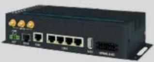 | |
| 2 | Wing for wall mounting (screwed on the router) |  | 2 pcs |
| 3 | 2-pin terminal block for power supply (deployed on the router) |  | 1 pcs |
| 4 | 14-pin terminal block for RS232, RS485, CAN BUS, and I/O (deployed on the router) |  | 1 pcs |
| 5 | Printed Quick Start Guide Leaflet |  | 1 pcs |
Table 4: Contents of Package
1.6 Product Dimensions
For the dimensions of the router see the figures below. Note that all sizes are measured in millimeters.
Variant with Wall Mounting Clip

text_image
OUT1 OUT0 IN1 IN0 USR PWR 47 96 210.3 Φ5 ADVANTECH ICR-4400 9.6 72 195 48.2 WIFI PWR RST ETH2 ETH1 ETH0 USB SERIAL & I/O 1.2 222.7Figure 2: Router Dimensions – Front, Top and Right view with Wall Mounting holder
Variant with DIN Rail Clip

text_image
OUT1 OUT0 IN1 INO USR PWR 55 110 55 47 56,2 9,6 ADVANTECH ICR-4000 195 56,2 47,0 WIFI1 PWR + - RST ETH2 ETH1 ETH0 USB SERIAL & I/OFigure 3: Router Dimensions – Front, Top and Right view with DIN holder
1.7 Mounting Recommendations
The router can be placed:
- on a flat surface,
- on a wall using the wall mounting clip (see Chapter 1.8),
- on a DIN rail EN 60715 with the metal DIN rail clip (see Chapter 1.9)
For most applications with a built-in router within a switchboard, it is possible to recognize two kinds of environments:
- A non-public, industry environment of low voltage with high interference,
- a public environment of low voltage and without high interference.
For both of these environments, it is possible to mount the router to a switchboard, after which there is no need to have examination immunity or issues in connection with EMC according to EN 61439-1:2011.
!
In compliance with the EN 61439-1:2011 specification, it is necessary to observe the following assembly instructions for a router attached to a switchboard:
- For whip antennas it is recommended to observe a minimum distance of 6 cm from cables and metal surfaces on every side in order to avoid interference. When using an external antenna separate from the switchboard it is necessary to fit a lightning conductor.
- When mounting a router on sheet-steel we recommend using a cable antenna.
-
For all cables, we recommend to bind the bunch, and for this we recommend:
-
The length of the bunch (the combination of power supply and data cables) should be a maximum 1.5 m. If the length of data cables exceeds 1.5 m or if the cable is leading towards the switchboard, we recommend installing surge protectors.
- Data cables must not be binded together with mains voltage cables 230V / 50Hz or 120V / 60Hz .
- Sufficient space must be left between each connector for the handling of cables,
- To ensure the correct functioning of the router we recommend the use of an earth-bonding distribution frame for the grounding of the grounding screw, see Chapter 2.5.
1.8 Wall Mounting

The wall mounting clip is supplied with the router as standard accessories.
The router can be screwed to a wall (or another surface) using the wall mounting clips. Two wall mounting clips are assembled to the router during the production and need to be rotated as shown of Figure 4.
There are two wholes on the clip with a diameter of 5 millimeters. For detailed information about the mounting dimensions see Figure 2 in Chapter 1.6.

When mounting the wall mounting clip, tighten the screws with max. torque of 0.4 Nm.

natural_image
Technical diagram of a mechanical component with two vertical panels and green circular arrows indicating rotation or movement (no text or symbols)Figure 4: Rotated Wall Mounting Clips
1.9 DIN Rail Mounting

The DIN rail clips are not supplied with the router as standard accessories, but they can be ordered by the order code BB-DIN-ICR32 (two pieces for one router).
Two DIN rail clips can be assembled to the router and used to mount it to the DIN rail which meets the 60715 standards. The default position of the clips is shown in Figure 5. If needed, the clips can be rotated vertically as well.

When mounting the clips, tighten the screws with max. torque of 0.4 Nm.

natural_image
Two identical black electrical connectors with green circular arrows indicating rotation or clockwise motion (no text or symbols)Figure 5: Default Position of the DIN Rail Clips
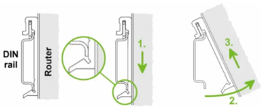
To remove the router from the DIN rail, it is necessary to lightly push down the router so that the bottom part of the DIN rail clip hitched to the DIN rail get out of this rail and then fold out the bottom part of the router away from the DIN rail as shown in Figure 6.
text_image
DIN rail Router 1. 2. 3.Figure 6: Removing Router from the DIN Rail
1.10 Product Label
An example of the product label, with all the information printed on it, is in the figure below.

text_image
ICR-4401 Industrial Router 9-48V === 1.6A MAX CE UK CA E8 10R-06 11459 Advantech Czech s.r.o., Sokolska 71 56204 Usti nad Orlici, Czech Republic P/N: ICR-4401 Rev.X.X S/N: ACZ1100123456785 MAC: 01:23:45:67:89:AB Def. password: P23456785hFigure 7: Label Example
2. Hardware Functionality
See Chapter 1.2 for the product hardware overview. Table 1 lists a short description of the hardware, including the links to the chapters with a detailed description.
2.1 Antennas Interfaces
Three R-SMA connectors WIFI1 are available for the connection of the WiFi antennas.

Recommended tightening moment for screwing the antenna to the SMA connector is 0.9 Nm.
2.2 Ethernet Interfaces
The RJ45 panel socket is used for four ETH0 (switched) and one ETH1 Ethernet interfaces. The pinout of the socket is shown in Figure 10 and described in Table 5.

text_image
① ⑧Figure 8: Ethernet Connector Pinout of RJ45 Socket
| Pin | 10base-T & 100base-T | 1000base-T | PoE PSE (Mode B) |
| 1 | Tx+ (Transmit Data+) | BI_DA+ (BiDirectional pair A+) | — |
| 2 | Tx- (Transmit Data-) | BI_DA- (BiDirectional pair A-) | — |
| 3 | Rx+ (Receive Data+) | BI_DB+ (BiDirectional pair B+) | — |
| 4 | — | BI_DC+ (BiDirectional pair C+) | PoE PSE+ (positive pole) |
| 5 | — | BI_DC- (BiDirectional pair C-) | PoE PSE+ (positive pole) |
| 6 | Rx- (Receive Data-) | BI_DB- (BiDirectional pair B-) | — |
| 7 | — | BI_DD+ (BiDirectional pair D+) | PoE PSE- (negative pole) |
| 8 | — | BI_DD- (BiDirectional pair D-) | PoE PSE- (negative pole) |
Table 5: Ethernet Connector Pinout Description of RJ45 Socket

All four ETH0 ports can be used for PoE PSE if the router is equipped with this feature. For more information about the PoE, see Chapter 2.3; for technical parameters, see Chapter 4.7.

The isolation barrier of the Ethernet ports against the ground is 1500 V.
2.3 Power over Ethernet (PoE) PSE
Available only for models with PoE PSE feature; see Chapter 1.3 for the order codes.
The IEEE 802.3af/PoE (Type 1) and IEEE 802.3at/PoE+ (Type 2) standards are supported. The device is Mode B compliant.
You can use thepse command to control the PoE functionality; see the Commands and Scripts application note.

The router power supply must be 48 V DC to work as the PoE PSE device.
The PoE PSE feature allows the router to power other devices over the Ethernet socket; see the functional scheme in Figure 9.

flowchart
graph TD
    A["Powered devices"] --> B["Power source equipment"]
    C["Powered devices"] --> D["Advantech router"]
    D --> E["Internet"]
    F["Power supply"] --> D
    G["SCADA/FTP"] --> H["Internet"]
Figure 9: PoE PSE Funcional Scheme
The PoE PSE is supported by all four ETH0 network sockets and can be enabled separately in the Ethernet configuration pages; see the router configuration manual [1], Chapter Configuration -> Ethernet Configuration, for details. For the Ethernet socket pinout, see Chapter 2.2.
For a current PoE state, see the General status page in the GUI. When enabled and an external device is powered, you can find current, voltage, power, and power class information here.
The following table summarizes the PoE parameters.
| PoE PSE parameters | |
| Required power supply parameters | 48 V / up to 135 W |
| Power available to a PoE device | 12.95 W / per port |
| Required power supply wattage for a PoE device | 15.40 W / per port |
| Power available to a PoE(+) device | 25.50 W / per port |
| Required power supply wattage for a PoE(+) device | 30.0 W / per port |
Table 6: PoE PSE Parameters
PoE Power Budget Examples
Example #1
This example is for the Advantech RPS-ICR4-WR2-PSE power supply, which can supply a power of 65 W. We will use 15 W as the maximum router power consumption; see Chapter 4.1. You can use this power supply to power:
- up to three PoE devices (3 × 15.4 W + 15 W = 61.2 W < 65 W),
- just one PoE+ device (1 × 30 W + 15 W = 45 W < 65 W).
Example #2
To power four PoE+ devices, you should power the router with a minimum power supply of 135 W; see the following calculation:
- required power supply wattage = 4 × 30 W + 15 W = 135 W.
Use a power supply with enough power to cover the required power consumption of all connected PoE devices, including the router itself. We recommend using a power supply with some power reserve.
!
2.4 SFP Cage
A hot-pluggable (SFP) network interface module with a speed of up to 10 Gbps can be settled into the ETH2 SFP cage.
Installing an SFP Module
To install a SFP module, see Figure 10 and follow these steps:
- You should use the bale clasp if the SFP module is equipped with it. If so, close the clasp before inserting the SFP module.
- Hold the SFP module with the hardware label facing up.
- Insert the SFP module into the ETH2 slot and gently push on it until it snaps into the slot tightly.

text_image
AD+HTECH OUTR OUTR WIFI USB POWER L1 L2 L3 L4 L5 L6 L7 L8 L9 L10 L11 L12 L13 L14 L15 L16 L17 L18 L19 L20 L21 L22 L23 L24 L25 L26 L27 L28 L29 L30 L31 L32 L33 L34 L35 L36 L37 L38 L39 L40 L41 L42 L43 L44 L45 L46 L47 L48 L49 L50 L51 L52 L53 L54 L55 L56 L57 L58 L59 L60 L61 L62 L63 L64 L65 L66 L67 L68 L69 L70 L71 L72 L73 L74 L75 L76 L77 L78 L79 L80 L81 L82 L83 L84 L85 L86 L87 L88 L89 L90 L91 L92 L93 L94 L95 L96 L97 L98 L99 L100Figure 10: SFP Module Installation
See Table 7 for a list of successfully tested SFP modules on the product.
| Model Manufacturer | |
| SFP-GSM-20K Advantech | |
| ML-S+31Dout-10 | MaxLink |
| S-3553LC20D | MikroTik |
| SFP-PLUS-LR10-HPE | Hewlett Packard |
| SFP-TXCIS | OEM |
| TXM431-LR(UN) | TP-Link |
| UF-RJ45-1G | Ubiquiti |
Table 7: Tested SFP Modules
2.5 Power Supply
Two pin terminal connector with 3.5mm pitch is used to power the router. Corresponding connector is supplied with the router as a standard accessories.
| Pin Signal mark Description | ||
| 1 | VCC(+) | Positive pole of DC supply voltage (+9 to +48 V DC) |
| 2 | GND(-) | Negative pole of DC supply voltage |
Table 8: Power connector pinout

text_image
① ② 9 - 48 V DCFigure 11: Power Connector Pinout
Required power supply voltage for the router is between +9 V and +48 V DC, see the connection scheme on Figure 11. Protection against reversed polarity without signaling is built into the router. For correct operation it is necessary that the power source is able to supply power of 18 W (non-PoE version).
If the router is grounded, using the grounding screw, there is no protection against the reversed polarity. The negative pole of the DC power supply must be at the same voltage reference as the grounding screw. If not, a voltage difference between these two points might damage the router, and only an authorized service center can fix it.
The power voltage for the PoE router version must be 48 V DC to work as the PoE PSE device.
All metal parts, including the box, are connected together with the negative pole of the power supply (common pole). If recommended for the installation environment, protect the router by grounding it properly by the grounding screw, see Figure 12.
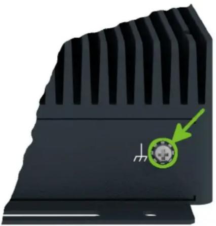
natural_image
Close-up of a black mechanical component with a green arrow pointing to a circular feature (no text or symbols visible)Figure 12: Position of the Grounding Screw
2.6 Low Power Mode
!
In applications requiring low power consumption (such as solar power - not 7/24 mode) is strictly recommended to use LPM mode prior to powering down the entire router.
LPM (Low Power Mode) is a router mode where the router is in sleep mode with minimal power consumption; see Chapter 4.1 for the LPM consumption. The router can be woken up from this mode by a signal applied to the BIN1 input or after a predetermined period of time. Putting the router into LPM mode can be done using the lpm command, see Commands and Scripts application note for more details.
2.7 I/O Port Interfaces
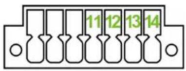
The I/O user interface is designed for binary input processing and binary output control. The pinout of the I/O interface is described in Figure 13 and Table 9. For detailed electrical parameters see Chapter 4.5. The functional scheme of connection for the binary input and binary output is in Figure 14.
text_image
11 12 13 14Figure 13: I/O Connector Pinout
Pin Signal mark Description
11 BIN0 The first binary input
12 BOUT0 The first binary output
13 BIN1 The second binary input
14 BOUT1 The second binary output
Table 9: Connection of I/O Ports
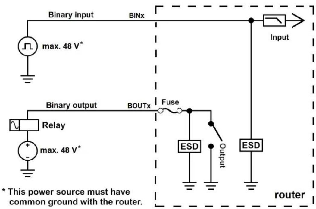
text_image
Binary input BINx Input max. 48 V* Binary output BOUTx Fuse Relay max. 48 V* ESD Output ESD * This power source must have common ground with the router. routerFigure 14: Functional Scheme of the Binary Interface
2.8 Serial Interfaces
The RS232, RS485 CAN serial interfaces together with the two I/O interfaces are physically connected to the 14-pin terminal block panel socket. All these interfaces are not isolated from the router. The pinout of this connector is described in Figure 15 and the tables below.
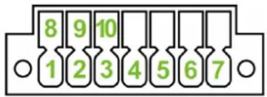
text_image
8 9 10 1 2 3 4 5 6 7Figure 15: Serial Connector Pinout
| Pin Signal mark Description | |
| 1 RXD Received Data | |
| 2 CTS Clear to Send | |
| 3 GND Ground | |
| 4 RTS Request to Send | |
| 5 TXD Transmit Data | |
Table 10: Connection of RS232
| Pin Signal mark Description | |
| 6 CAN_H CAN High | |
| 7 CAN_L CAN Low | |
Table 11: Connection of CAN Bus
| Pin Signal mark Description | |
| 8 B (+) In/Out | |
| 9 A (-) In/Out | |
| 10 GND Ground | |
Table 12: Connection of RS485
2.9 USB Port
There is one USB 2.0 host port with socket of USB-A type. USB Mass Storages and FTDI serial converters are supported. For a piece of advice, how to fix an unsupported FTDI chip, see the Commands and Scripts application note, chapter How to Use Unsupported FTDI Chip.

The USB port is disabled on overload to prevent its damage (connected device is trying to get too high current). The port is enabled again after the reboot of the router.
Mounting USB Flash Drive to the System
It is necessary to mount the USB flash drive to be able to access it in the system of the router. Follow these steps to mount the drive:
- Use the dmesg command to see the list of recently connected devices.
- In the output of the command find out the entry for the microSD card, for example: sda: sda1
- To mount the card to to mnt directory, use the mount command: mount /dev/sda1 /mnt

For more information about the commands for creating, mounting, checking and unmounting a file system on a USB Flash Drive, see the application note for Ext4_tools router app.
USB Socket Pinouts
USB socket pinouts is described in Figure 16 and Table 13.
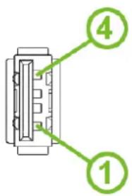
text_image
Diagram of a connector with labeled parts 1 and 4, showing internal structure and pin layout.Figure 16: USB Connector Pinout
| Pin | Signal mark | Description Data flow direction | |
| 1 | +5 V | Positive pole of 5 V DC supply voltage, 0.5 A | |
| 2 | USB data - | USB data signal – negative pole | Input/Output |
| 3 | USB data + | USB data signal – positive pole | Input/Output |
| 4 | GND | Negative pole of DC supply voltage |
Table 13: USB Connector Pinout
2.10 MicroSD Card Reader
The microSD card reader is located on the router's rear panel under a metal cover. This card reader allows the router to operate with microSD memory cards. The technical specifications are stated in the table below. The microSD card changing procedure is described below.
| Technical specifications of microSD card | ||
| Supported technologies SD, SDHC, SDXC | ||
| Supported capacity SDHC | SDXC | up to 32 GBfrom 32 GB to 512 GB |
| Supported microSD card filesystems | vfat, ext2, ext3, ext4 | |
Table 14: Technical Specifications of MicroSD Card
Inserting the microSD card:
- To remove an inserted microSD card, use the flat end of a spudger, or your fingernail, press the card slightly into its slot until you hear a click, release the card and it will pop out of its slot.
- To insert a microSD card push card into the slot with correct orientation as shown on the picture until it clicks into place.

text_image
microSD SDFigure 17: MicroSD Card Insertion

Mounting microSD Card to the System
It is necessary to mount the microSD card to be able to access it in the system of the router. Follow these steps to mount the card:
- Use the dmesg command to see the list of recently connected devices.
- In the output of the command find out the entry for the microSD card, for example: mmcblk0: p1
- To mount the card to to mnt directory, use the mount command: mount /dev/mmcblk0p1 /mnt

For more information about the commands for creating, mounting, checking and unmounting a file system on a microSD card, see the application note for Ext4_tools router app.
2.11 LED Status Indication
There are status LEDs on the top side of the router to provide router status information. Moreover, ETH0 and ETH1 connectors, located on the front panel, have two additional LEDs providing information about the port status.
| Caption | Color State | Description | ||
| [CS48] | PWR Green | OnBlinkingFast blinking | The router is booting up.The router booted up and is ready.The router firmware is being updated. | |
 | USR | Green | — | The function of this LED is user-defined. |
 | IN0 | Green | On | The first binary input is active. |
 | IN1 | Green | On | The second binary input is active. |
 | OUT0 | Green | On | The first binary output is active. |
 | OUT1 | Green | On | The second binary output is active. |
| ETH0 | Green | On | Selected 1 Gbps bit rate. | |
| ETH1 | Green | Off | Selected 100/10 Mbps bit rate. | |
| ETH0 | Yellow | On | The network cable is connected. | |
| ETH1 | Yellow | Blinking | Data transmission. | |
| Yellow | Off | The network cable is not connected. | ||
Table 15: LED Status Indication
2.12 Reset Functions

Consider creating a router configuration backup before performing the router's factory reset.
The RST button can be used in three different scenarios:
- Reset: Hold the RST button for less than 4 seconds; the router will reboot, applying its customized configuration. The router reset can be initiated by clicking the Reboot menu item in the router web GUI.
- Factory Reset: To restore the default factory configuration of the router, press and hold the RST button for more than 4 seconds. After that, the PWR LED turns off and on again. We recommend holding the RST button for 1 second after turning on the PWR LED.
- Emergency Factory Reset: If the router cannot boot up due to the incorrect configuration, turn off the router (disconnect the power supply). Then, push and hold the RST button, turn on the router and hold the RST button for at least 10 seconds. The router configuration will be set to the default one.

It is necessary to use a narrow screwdriver or any other small tool to press the RST button.
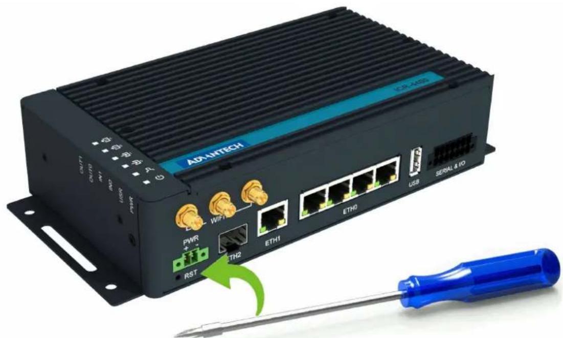
text_image
AD-AHTECH USB SERIAL & IO PWM ETH2 RST PWR + - RST ETH1 ETH0 PWM PWM PWM PWM PWM PWM PWM PWM PWM PWM PWM PWM PWM PWM PWM PWM PWM PWM PWM PWM PWM PWM PWM PWM PWM PWM PWM PWM PWM PWM PWM PWM PWM PWM PWM PWM PWM PWM PWM PWM PWM PWM PWM PWM PWM PWM PWM PWM PWM PWM PWTRFigure 18: Resetting the Router
3. First Use
3.1 Accessories Connection
Before putting the router into operation, it is necessary to connect all the components required to run your applications; see Chapter 1.2 for the hardware overview.
3.2 Router Configuration
Initial router configuration can be made via a web browser on your PC. Here you can perform router monitoring, configuration, and administration.
Connect the power supply to the router, see Chapter 2.5, and the router will boot up. Configure your PC to get the IP settings automatically from the network. Connect the network card of your PC to the default router LAN interface, Ethernet port ETH0, and the DHCP server will assign an IP address to your PC.
To get the router web interface, enter the https://192.168.1.1 address in a web browser. Please note that usage of the HTTPS protocol for secure communication over the network is required.
There is just the root user account created on the router by default. See the product label on the router for its default password ^1 . Log in to the web interface with the root user and his password. If logged in successfully, the user will have access to the router web interface, see Figure 19. See the router configuration manual [1] for a detailed description and examples of the router configuration.
!
After logging on to the device for the first time, we strongly recommend changing the default password due to security reasons.
!
For security reasons, we recommend regularly updating the router's firmware to the latest version. Downgrading the firmware to an older version than the production version or uploading firmware intended for a different device may cause the device's malfunction.
!
All routers have the WebAccess/DMP client pre-installed by default. The activated client periodically uploads router identifiers and configuration to the WebAccess/DMP server. See the configuration manual [1] , chapter Basic Information -> WebAccess/DMP Configuration, for more information.
| Status | General Status | |
| General WIFI Network DHCP IPsec WireGuard DynDNS System Log | ETH0 | |
| Configuration Ethernet VRRP PPPoE WIFI Backup Routes Static Routes Firewall NAT OpenVPN IPsec WireGuard GRE L2TP PPTP Services Expansion Port 1 Expansion Port 2 USB Port Scripts Automatic Update | IP Address : 10.04.0.91 / 255.255.252.0 IPv6 Address : fd00:a41::91 / 56 MAC Address : 02:AD:FF:00:00:91 Rx Data : 1.2 MB Tx Data : 52.4 KB » More Information « | |
| Customization Router Apps | ETH1 | |
| Administration Users Change Profile Change Password Set Real Time Clock Backup Configuration Restore Configuration Update Firmware Reboot Logout | IP Address : 10.65.0.91 / 255.255.252.0 IPv6 Address : fd00:a42::91 / 56 MAC Address : 02:AD:FF:02:08:91 Rx Data : 155.6 KB Tx Data : 28.3 KB » More Information « | |
| WIFI AP 1 | ||
Figure 19: Router's Web Interface

A detailed description of the router settings in the web interface can be found in the configuration manual [1] of the router.
4. Technical Parameters
4.1 Basic Parameters
| Parameter Description | ||
| Temperature range Operating | Storage | -40 °C to +75 °C (-40 °F to +167 °F)1-40 °C to +85 °C (-40 °F to +185 °F) |
| Humidity Operating | Storage | 5 to 95 % relative humidity non condensing5 to 95 % relative humidity non condensing |
| Altitude Operating 2000 m / 70 kPa | ||
| Degree of protection IP30 | ||
| Supply voltage 9 – 48 V DC | ||
| Battery for RTC CR1225 | ||
| Consumption for non-WiFi (WiFi) version | IdleAverageMaximumLPM mode | 5.4 W (7.3 W)5.6 W (7.9 W)11.6 W (15.1 W) / 142 W23 mW / 170 mW3 |
| Dimensions of device (w/o wings) | 195 × 110 × 47 mm (7.68" × 4.33" × 1.85") | |
| DIN rail clip specification | 2 pcs of DIN 35 mm, EN 60715 | |
| Total weight | 1250 g (2.76 lbs) | |
| Antenna connectors | WIFI1 | R-SMA connectors for WiFi – 50 Ω |
| Interfaces | ETH0ETH1ETH2USBSERIAL & I/O | RJ-45 socket for 1Gb Ethernet SWITCHRJ-45 socket for 1Gb EthernetSFP cage for up to 10 Gbps SFP modulesUSB-A14-pin panel socket terminal block for RS232,RS485, CAN bus and I/O interfaces |
Table 16: Basic Parameters
4.2 Standards and Regulations
| Parameter Description | |
| Radio | EN 301 893, EN 300 328 |
| EMC | EN 301 489-1, EN 301 489-17, EN 61000-4-2, EN 61000-4-3, EN 61000-4-4, EN 61000-4-5, EN 61000-4-6, EN 61000-6-2, EN 55032 |
| Safety EN 62368-1, IEEE 802.3 | |
| Mechanical | EN 60068-2-27, EN 60068-2-64, EN 60529 |
| Climatic | EN 60068-2-2, EN 60068-2-1, EN 60068-2-14, EN 60068-2-30 |
| Transportation | E-Mark (E8), homologation number: 10R - 06 11459 ^1 |
| National CE, UKCA compliant | |
| Environmental | REACH, RoHS3 and WEEE compliant |
Table 17: Standards and Regulations
4.3 Type Tests and Environmental Conditions
| Phenomena Test Description Test levels | |||
| ESD | EN 61000-4-2 | Enclosure contact | ± 6 kV (crit. A) |
| RF field AM modulated | EN 61000-4-3 Enclosure | 20 V/m (crit. A) | (80 - 1000 MHz)10 V/m (crit. A)(1 - 6 GHz) |
| Fast transient EN 61000-4-4 Signal ports | Power portsEthernet ports | ±1 kV (crit. A)±2 kV (crit. A)±1 kV (crit. A) | |
| Surge EN 61000-4-5 Ethernet ports | Power ports | ± 1 kV (crit. A), shielded cab.±1 kV (crit. A) | |
| RF conducted | EN 61000-4-6 | All ports | 10 V/m (crit. A)(0.15 - 80 MHz) |
| Radiated emission | EN 55032 | Enclosure | Class B |
| Conducted emission | EN 55032 | Signal portsPower portsEthernet ports | Class BClass BClass B |
| Dry heat | EN 60068-2-2 | Test Bb, storage +85 °C, operation +75 °C | |
| Cold | EN 60068-2-1 | Test Ab, storage -40 °C, operation -40 °C | |
| Damp heat | EN 60068-2-78 | 95 % rel. humidity (+40°C) | |
| Dry heat, cyclic | EN 60068-2-30 | +55 °C / +25 °C, rel. humidity 95%, 6 h - 6 h | |
| Dry heat | EN 60068-2-2 | Test Bb, storage +85 °C, operation +75 °C | |
| Thermal shock/ temp. variation | EN 60068-2-14 Test Nb, -40 °C/+75 °C, 3h/3h, 2 cycles, 3 K/min | ||
| Degrees of protection provided by enclosures | EN 60529 | IP30 | |
| Vibration, broad-band random | EN 60068-2-64 | Spectrum A.3 cat 1, breakpoints A.6 cat 1 | |
| Shock | EN 60068-2-27 50 m/s | 2, 11 ms, half sine, 10 in each dir. | |
Table 18: Type Tests and Environmental Conditions
4.4 Parameters of WiFi
| Parameter Description | |
| Short Module Description | Dual Band 2.4/5GHz 3x3 WiFi 5 (802.11ac Wave 1) |
| Supported Standards | IEEE: 802.11ac compliant & compatible with 802.11a/b/g/n |
| Antenna Connectors 3x3 MIMO R-SMAInput impedance: 50 Ω | |
| Data Rate(3x3 MIMO OFDM) | Up to 600 Mbps @ 2.4 GHzUp to 1300 Mbps @ 5 GHz |
| Frequency Ranges | 2.412 – 2.472 GHz4.920 – 5.825 GHz |
| Spectrum Widths 20/40MHz @ 2.4GHz20/40/80MHz @ 5GHz | |
| Modulation Techniques OFDM: BPSK, QPSK, DBPSK, DQPSK, 16-QAM, 64-QAM, 256-QAM | |
| 2.4 GHz supported channels | 1, 2, 3, 4, 5, 6, 7, 8, 9, 10, 11, 12, 13 |
| 5 GHz supported channels | 36, 38, 40, 42, 44, 46, 48, 52, 56, 60, 64, 100, 104, 108, 112, 116, 120, 124, 128, 132, 136, 140, 149, 153, 157, 161, 165 |
| Type of device | Access point (AP)Station (STA)Multi-role (AP & STA) |
| Key Features | Spatial Multiplexing, Cyclic-Delay Diversity (CDD), Low-Density Parity Check (LDPC) Codes, Maximal Ratio Combining (MRC), Space Time Block Code (STBC), Dynamic Frequency Selection (DFS), IEEE 802.11d, e, h, i, j, k, r, v time stamp, and w standards |
| Security – Standards | WPA, WPA2, WPA3, 802.1X |
| Security – Encryption | WEP, TKIP, AES |
| Security – EAP Types | EAP-FAST, EAP-TLS, EAP-TTLS, PEAP-GTC, PEAP-MSCHAPv2, PEAP-TLS, LEAP |
| TX Power (per chain) | Max. 21 dBm @ 2.4 GHzMax. 18 dBm @ 5 GHz |
Table 19: Technical Parameters of WiFi
4.5 Parameters of I/O Ports
Electrical characteristics of the binary inputs are in Table 20. Status of the binary input can be retrieved in the router's web interface (on the General Status page) or by the status ports and io get commands, see Commands and Scripts application note.
| Logical ^1 | Voltage Current Status | 2 |
| 1 3 V 0.5 mA Off | ||
| 0 5 V 0.8 mA On | ||
| 0 12 V 1.6 mA On | ||
| 0 48 V 3.4 mA On |
Table 20: Electrical Characteristics of Binary Inputs
The maximum binary output load is 500 mA at 48 V.
4.6 Parameters of Serial Interfaces
Supported parameters of the RS232 and RS485 interfaces, which can be configured in Expansion Port 1 resp. Expansion Port 2 menu items, are in Table 21.
| Parameter | Description |
| Baudrate | 300, 600, 1200, 2400, 4800, 9600, 19200, 38400, 57600, 115200, 230400. |
| Data Bits | 5, 6, 7, 8. |
| Parity | none, even, odd. |
| Stop Bits 1, 2. | |
| Flow Control | none, hardware. |
Table 21: Parameters of Serial Interfaces
4.7 Parameters of PoE
For more information about the PoE PSE feature, including the parameters, see Chapter 2.3.
4.8 System Configuration
The main parameters of the system are listed in Table 22.
| Parameter Description | |
| CPU architecture | Quad-Core ARMv8-A (core Cortex-A72) |
| CPU frequency 1200 MHz | |
| CPU power 4.72 DMIPS/MHz | |
| Flash memory 4 MB of NOR | |
| 4 096 MB of eMMC• 838 MB for Router Apps• 512 MB for customer data | |
| RAM size 1 024 MB | |
| Watchdog HW watchdog | |
| RTC | Battery backup RTC |
| TPM | Trusted Platform Module (TPM) 2.0 |
Table 22: System Configuration
Appendix A: Troubleshooting
If you cannot connect to the router from your PC, your network card may be configured in such a way that it is not possible to connect to the router. Take one or more of the following steps in order to solve the problem:
- Make sure your PC's network card is configured to obtain the IP address form the DHCP server (by default the DHCP server is running in the router).
- Connect the router to the PC via Switch.
- Connect the router to the PC, start the router first and then start the PC after the router's initialization.

Ethernet connection fails or is not establishing.
- It is possible to turn auto negotiation off and set a rate and duplex manually on the Ethernet interface of the router. Available on "LAN Configuration" page in the router.
I cannot connect from the Internet to the device behind the router. I have NAT enabled.
- The device's gateway has to be configured so it points to the router.
I can't access my Web server placed behind the router over NAT.
- The remote HTTP access to the router has to be disabled on "NAT Configuration" page in the router. Also enable "Send all remaining incoming packets to default server" feature and fill in the IP address of your Web server. On the Web server, the default gateway has to be the IP address of the router.
DynDNS doesn't work.
- If the same IP address is recorded in your canonic name as a dynamically assigned address, it means that the provider is using NAT or a firewall.
- You can verify NAT using ping to your server with static address and then compare with router's IP address.
- You can verify a Firewall by accessing remotely to the router's Web interface.
-
The operator may not provide the address of DNS server and without DNS server's address it is impossible to connect to the dyndns.org server. The following messages will be shown in the System Log:
-
DynDNS daemon started
- Error resolving hostname: no such file or directory
- Connect to DynDNS server failed
L2TP or IPSec isn't establishing.
- Check the "System Log" page for error messages.
IPSec tunnel establishes but the communication does not run.
- Probably there are bad routing rules defined in the connected devices, or the default gateway.
Serial communication is not working.
- Verify that the router model supports serial communications. Also verify the serial communication settings. To do so, open the router's configuration menu via the web browser, select the appropriate "Expansion Port" from "Configuration" part of the menu and verify the settings.
Is the router Cisco compatible? Can I use the Cisco configuration?
- No, the Firmware in the router (Conel OS) is based on Linux with BusyBox. Thus the Cisco configuration cannot be used. But network connections are defined by standards so connecting the router to the Cisco or other networking devices is possible and will be compatible.
FTP or SFTP does not work
- FTP will work on v2 routers only. You can use SFTP on all routers to transfer files to/from the router. If having troubles with FTP on v2 routers, make sure you have FTP enabled: "Configuration" section, "Services", "FTP". Then you can connect with any client on port 21 with name and password same as for the Web interface. If having troubles with SFTP, make sure you have SSH enabled: "Configuration" section, "Services", "SSH". Then you can connect with any client on port 22 with name and password same as for the Web interface.
How can I connect to the router's command line? (SSH, Telnet)
- You can use SSH on all routers or Telnet on v2 routers only. SSH is enabled by default, but you can verify in Web interface in "Configuration" section, "Services", "SSH". Then connect with any SSH client on port 22 of the router. User and password is the same as for the Web interface. Telnet on v2 routers can be enabled here: "Configuration" section, "Services", "Telnet".
Appendix B: Customer Support
Customer Support for Europe
Advantech Czech s.r.o.
Sokolska 71
562 04, Usti nad Orlici
Czech Republic
Phone: +353 91 792444
Fax: +353 91 792445
E-mail: iiotcustomerservice@advantech.eu
Web: www.advantech.com
Customer Support for NAM
Advantech B+B SmartWorx
707 Dayton Road
Ottawa, IL 61350 USA
Phone: +1-800-346-3119 (Monday – Friday, 7 a.m. to 5:30 p.m. CST)
Fax: +1-815-433-5109
E-mail: support@advantech-bb.com
Web: www.advantech-bb.com
Customer Support for Asia
Phone: +886-2-2792-7818 #1299 (Monday – Friday, 9 a.m. to 5:30 p.m. UTC+8)
Web: www.advantech.com
Appendix C: Regulatory & Safety Information
Safety Notices
!
Please, observe the following instructions:
- The router must be used in compliance with all applicable international and national laws and in compliance with any special restrictions regulating the utilization of the router in prescribed applications and environments.
- To prevent possible injury and damage to appliances and to ensure compliance with all relevant provisions, use only the original accessories. Unauthorized modifications or the use of unapproved accessories may result in damage to the router and/or a breach of applicable regulations. Unauthorized modifications or use of unapproved accessories may void the warranty.
- The router can not be opened.
- Caution! This equipment is not suitable for use in locations where children are likely to be present.
- Power supply must not exceed 48 V DC max.
- Do not expose the router to extreme ambient conditions. Protect the router against dust, moisture and high temperature.
- Only routers with appropriate certification and labelling should be used in locations where flammable and explosive materials are present, including gas stations, chemical plants, or locations in which explosives are used. We remind users of the duty to observe the restrictions concerning the utilization of radio devices at such places.
- Switch off the router when travelling by plane. Utilization of the router on a plane may endanger the operation of the plane or interfere with the mobile telephone network, and may be unlawful. Failure to observe these instructions may result in the suspension or cancellation of telephone services for the respective client and / or may result in legal sanctions.
- When using the router in close proximity to personal medical devices, such as cardiac pacemakers or hearing aids, you must proceed with heightened caution.
- The router may cause interference when used in close proximity to TV sets, radio receivers or personal computers.
- It is recommended that you create an appropriate copy or backup of all important settings that are stored in the memory of the device.
Product Disposal Instructions
The WEEE (Waste Electrical and Electronic Equipment: 2012/19/EU) directive was introduced to ensure that electrical/electronic products are recycled using the best available recovery techniques to minimize the environmental impact. This product contains high quality materials and components which can be recycled. At the end of it's life this product MUST NOT be mixed with other commercial waste for disposal. The device contains a battery. Remove the battery from the device before disposal. The battery in the device needs to be disposed of apart accordingly. Check the terms and conditions of your supplier for disposal information.
Appendix D: Related Documents
[1] Configuration Manual for v4 Platform

[EP] Product-related documents and applications can be obtained on Engineering Portal at https://icr.advantech.cz/download address.
C ∈
We, Advantech Czech s.r.o., declare that the radio equipment narrated in this user's manual complies with Directive 2014/53/EU (WiFi version) and with the essential requirements and other relevant provisions of Directives 2014/30/EU and 2014/35/EU (non-WiFi version).
UK CA
We, Advantech Czech s.r.o., declare that the radio equipment narrated in this user's manual complies with Radio Equipment Regulations 2017 (S.I. 2017 No. 1206) and with the Electromagnetic Compatibility Regulations 2016 (S.I. 2016 No. 1091 and S.I. 2016 No. 1101).
The full text of the EU Declaration of Conformity is available at the following internet address: icr.advantech.cz/eudoc