BB-SR30400015 - Router Advantech - Free user manual and instructions
Find the device manual for free BB-SR30400015 Advantech in PDF.

User questions about BB-SR30400015 Advantech
0 question about this device. Answer the ones you know or ask your own.
Ask a new question about this device
Download the instructions for your Router in PDF format for free! Find your manual BB-SR30400015 - Advantech and take your electronic device back in hand. On this page are published all the documents necessary for the use of your device. BB-SR30400015 by Advantech.
USER MANUAL BB-SR30400015 Advantech
LTE Industrial Router
SmartFlex SR304
USER MANUAL
text_image
SmartFlex RS232 RS485 DIV GPS ANT SIM WAN DAT WIFI IN0 IN1 OUT ETHO ETH1 USB PWR IN0 IN1 OUT OUT PWR USR POE
text_image
SmartFlex RS232 RS485 DIV GPS ANT SIM WAN DAT WIFI IN0 IN1 OUT ETH0 ETH1 USB PWR PWR USR POE IN1 OUTADVANTECH
© 2023 Advantech Czech s.r.o. No part of this publication may be reproduced or transmitted in any form or by any means, electronic or mechanical, including photography, recording, or any information storage and retrieval system without written consent. Information in this manual is subject to change without notice, and does not represent a commitment on the part of Advantech.
Advantech Czech s.r.o. shall not be liable for incidental or consequential damages resulting from the furnishing, performance, or use of this manual.
All brand names used in this manual are the registered trademarks of their respective owners. The use of trademarks or other designations in this publication is for reference purposes only and does not constitute an endorsement by the trademark holder.
Used symbols

Danger – Information regarding user safety or potential damage to the router.

Attention - Problems that can arise in specific situations.

Information, notice – Useful tips or information of special interest.

text_image
CE UK CA
TÜVRheinland ^®
COTI
ISO 9001
Contents
1 Safety Instructions 2
2 WEEE directive 3
3 Router Description 4
3.1 Usage of the Router 5
4 Contents of Package 8
5 Router Design 9
5.1 Router versions 9
5.2 Product Revisions 11
5.3 Delivery identification 12
5.4 Order codes 13
5.5 Basic dimensions of the router box 15
5.6 Mounting Recommendations 15
5.7 Removal from the DIN rail 16
5.8 Description of the rear panel 17
5.9 Description of the front panel 17
5.9.1 Status indication 18
5.9.2 Power connector PWR 19
5.9.3 Antenna connector ANT, DIV, GPS and WiFi 21
5.9.4 SIM card reader 22
5.9.5 MicroSD card reader 23
5.9.6 Ethernet Ports (ETH0 and ETH1) 25
5.9.7 Power over Ethernet (PoE) 26
5.9.8 USB Port 28
5.9.9 I/O Port 29
5.9.10 Reset 31
5.10 Interfaces Description 32
5.10.1 SWITCH interface 32
5.10.2 RS232-RS485/422 interface 34
5.10.3 RS485-RS485 interface 37
5.10.4 RS232-RS485-ETH interface 38
6 First Use 41
6.1 Connecting the router before first use 41
6.2 Start 42
6.3 Configuration 42
6.3.1 Configuration by web browser 42
7 Technical Parameters 44
7.1 Basic parameters 44
7.2 Standards and Regulations 45
7.3 Type tests and environmental conditions 46
7.4 Technical parameters of Cellular Module 47
7.5 Parameters of GNSS 48
7.6 Technical parameters of WiFi 48
7.7 Technical parameters of I/O port 49
7.8 Technical Parameters of Power over Ethernet (PoE) 49
7.9 Other Technical Parameters 50
8 Related Documents 51
9 Troubleshooting 52
9.1 FAQ 52
10 Customer Support 55
List of Figures
1 Access to the Internet from LAN 5
2 Backed up access to the Internet 6
3 Using VPN tunnel 6
4 Serial Gateway 7
5 Contents of package 8
6 Basic version (plastic) 9
7 Basic version with WiFi (plastic) 9
8 Basic version (metal) 9
9 Basic version with WiFi (metal) 9
10 Version SWITCH (plastic) 10
11 Version SWITCH and WiFi (plastic) 10
12 Version RS232-RS485 (plastic) 10
13 Ver. RS232-RS485 & WiFi (plastic) 10
14 Version RS232-RS485-ETH (plastic) 10
15 Version SWITCH (metal) 10
16 Version SWITCH and WiFi (metal) 10
17 Version RS232-RS485 (metal) 10
18 Version RS232-RS485 & WiFi (metal) 10
19 Version RS232-RS485-ETH (metal) 10
20 RS232-RS485-ETH & WiFi (plastic) 11
21 RS232-RS485-ETH & WiFi (metal) 11
22 RS485-RS485 (metal) 11
23 Label examples 12
24 Basic dimensions of the router box 15
25 Default position of plastic and metal DIN rail clip 16
26 Removal from the DIN rail 16
27 SmartFlex front panel 17
28 Power connector 19
29 Connection of power supply 19
30 Connecting the antenna 21
31 SIM cards 22
32 MicroSD card 23
33 Ethernet connector 25
34 Connection of Ethernet cable 25
35 PoE PD usage 26
36 PoE PSE usage 27
37 USB connector 28
38 I/O connector 29
39 Binary connection 30
40 Router reset 31
41 Version with SWITCH board 32
42 Version with RS232-RS485/422 interface 34
43 RS232 connector 35
44 RS485/422 connector 35
45 Connection of jumpers 36
46 Version with RS485-RS485 interface 37
47 RS485 connector 37
48 Version with RS232-RS485-ETH interface 38
49 Ethernet connector 38
50 RS485 connector 39
51 RS232 connector 39
52 Router connection 41
53 Entering the IP address of the router 42
54 Entering login information 43
55 Router web interface 43
List of Tables
1 Router versions 9
2 HW Revisions History 11
3 Delivery identification 12
4 Order codes overview 13
5 Power over Ethernet 13
6 Type of router box 14
7 Type of power supply 14
8 Examples of order code 14
9 Front panel description 17
10 LED status indication 18
11 Connection of power connector 19
12 Technical specifications of microSD card 23
13 Ethernet connector pinout 25
14 Insulation strength of Ethernet ports 25
15 Connection of USB connector 28
16 Connection of I/O port 29
17 Characteristics of inputs 29
18 Description of router reset and restart 31
19 State indication of the SWITCH interface 33
20 SWITCH interface parameters 33
21 Connection of RS232 connector 34
22 Connection of RS485 connector 35
23 Connection of RS422 connector 35
24 Technical specification of RS232 and RS485 36
25 Connection of RS485 connector 37
26 Connections of the Ethernet Connector 38
27 Connections of Terminal Block Connector RS485 39
28 Connections of Terminal Block Connector RS232 39
29 State indication of the RS232-RS485-ETH interface 40
30 Technical specification of RS232, RS485 and Ethernet 40
31 Basic parameters 44
32 Standards and Regulations 45
33 Type tests and environmental conditions 46
34 Technical parameters of cellular module 47
35 Technical parameters of GNSS 48
36 Technical parameters of WiFi 48
37 Characteristics of inputs 49
38 PoE PD: parameters for opposite PSE 49
39 PoE PSE parameters 49
40 Other technical parameters 50
1. Safety Instructions
!
Please, observethefollowinginstructions:
- The router must be used in compliance with all applicable international and national laws and in compliance with any special restrictions regulating the utilization of the router in prescribed applications and environments.
- To prevent possible injury and damage to appliances and to ensure compliance with all relevant provisions, use only the original accessories. Unauthorized modifications or the use of unapproved accessories may result in damage to the router and/or a breach of applicable regulations. Unauthorized modifications or use of unapproved accessories may void the warranty.
• The router can not be opened.
- Turn off the router and disconnect it from power supply before handling the SIM card.
- Caution! This equipment is not suitable for use in locations where children are likely to be present. The SIM card could be swallowed by small children.
• Power supply must not exceed 60 V DC max.
- Do not expose the router to extreme ambient conditions. Protect the router against dust, moisture and high temperature.
- Only routers with appropriate certification and labelling should be used in locations where flammable and explosive materials are present, including gas stations, chemical plants, or locations in which explosives are used. We remind users of the duty to observe the restrictions concerning the utilization of radio devices at such places.
- Switch off the router when travelling by plane. Utilization of the router on a plane may endanger the operation of the plane or interfere with the mobile telephone network, and may be unlawful. Failure to observe these instructions may result in the suspension or cancellation of telephone services for the respective client and / or may result in legal sanctions.
- When using the router in close proximity to personal medical devices, such as cardiac pacemakers or hearing aids, you must proceed with heightened caution.
- The router may cause interference when used in close proximity to TV sets, radio receivers or personal computers.
- It is recommended that you create an appropriate copy or backup of all important settings that are stored in the memory of the device.
!
2. Product Disposal Instructions
The WEEE (Waste Electrical and Electronic Equipment: 2012/19/EU) directive was introduced to ensure that electrical/electronic products are recycled using the best available recovery techniques to minimize the environmental impact. This product contains high quality materials and components which can be recycled. At the end of it's life this product MUST NOT be mixed with other commercial waste for disposal. The device contains a battery. Remove the battery from the device before disposal. The battery in the device needs to be disposed of apart accordingly. Check the terms and conditions of your supplier for disposal information.
3. Router Description
SmartFlex SR304 is an industrial cellular router intended for the market in Europe, Middle East and Africa (EMEA) areas. This device may also be operated in south-eastern Asia. This router is an ideal device for wireless communication in mobile networks that make use of LTE, HSPA+, UMTS, EDGE or GPRS technology. Due to the high speed of data transfer up to 150 Mbps (download) and up to 50 Mbps (upload) is this router an ideal solution for specialized M2M devices and IoT as well as for wireless connection of traffic and security camera systems, individual computers, LAN networks, automatic teller machines (ATM) and other self-service terminals.
The standard configuration includes two Ethernet 10/100 ports, one USB 2.0 Host port, two binary inputs and one output (I/O connector). The device also has two readers for 3 V and 1.8 V SIM cards, which are located on the rear panel of the router. The router also includes a microSD card port that supports up to 64 GB card storage (32 GB in the case of SDHC cards). The router can be equipped with a WiFi module, but this must be part of the initial configuration – it cannot be assembled to the router at some point in the future.
The router can be equipped with PoE PD (Power over Ethernet – Powered Device), which allows the router to be powered via Ethernet. It can also be equipped with PoE PSE (Power over Ethernet – Power Source Equipment), which lets the router to power other devices via Ethernet. The SmartFlex router can also be configured with a wide variety of port options. These can be SWITCH – three switched Ethernet ports; RS232-RS485/422 – combination of serial interfaces; RS232-RS485-ETH – combination of serial interfaces and Ethernet port with higher insulation. The router can be provided in either a plastic or metal casing, depending upon the customer's requirements.
Configuration of the router may be done via a password-protected Web interface. Web interface provides detailed statistics about the router's activities, signal strength, detailed system log etc. The router supports the creation of VPN tunnels using IPSec, OpenVPN and L2TP to ensure safe communication. DHCP, NAT, NAT-T, DynDNS, NTP, VRRP, control by SMS, backup primary connection and many other functions are supported.
The router provides diagnostic functions which include automatically monitoring the PPP connection, automatic restart in case of connection losses, and a hardware watchdog that monitors the router status. The user may insert Linux scripts which are started on various actions. It is possible to create up to four different configurations for the same router. These configurations can be switched whenever necessary via Web interface, SMS or binary input status. The router can automatically upgrade its configuration and firmware from your central server. This allows for mass reconfiguration of numerous routers at the same time.
The router also supports additional software like R-SeeNet for permanent traffic monitoring of routers.

Examples of possible applications
- mobile office
- fleet management
- security system
-
telematic
-
telemetric
- remote monitoring
• vending and dispatcher machines
3.1 Usage of the Router
The router is primarily intended for these four basic situations:
I. Access to the Internet from LAN

flowchart
graph TD
    A["LAN"] -->|ETH| B["Configured router"]
    B --> C["Mobile network"]
    C --> D["Router"]
    D --> E["Internet"]
    style A fill:#f9f,stroke:#333
    style E fill:#bbf,stroke:#333
    linkStyle 0 stroke:#000,stroke-width:2px
    linkStyle 1 stroke:#000,stroke-width:2px
    linkStyle 2 stroke:#000,stroke-width:2px
    linkStyle 3 stroke:#000,stroke-width:2px
    linkStyle 4 stroke:#000,stroke-width:2px
    linkStyle 5 stroke:#000,stroke-width:2px
    linkStyle 6 stroke:#000,stroke-width:2px
    linkStyle 7 stroke:#000,stroke-width:2px
    linkStyle 8 stroke:#000,stroke-width:2px
    linkStyle 9 stroke:#000,stroke-width:2px
    linkStyle 10 stroke:#000,stroke-width:2px
    linkStyle 11 stroke:#000,stroke-width:2px
    linkStyle 12 stroke:#000,stroke-width:2px
    linkStyle 13 stroke:#000,stroke-width:2px
    linkStyle 14 stroke:#000,stroke-width:2px
    linkStyle 15 stroke:#000,stroke-width:2px
    linkStyle 16 stroke:#000,stroke-width:2px
    linkStyle 17 stroke:#000,stroke-width:2px
    linkStyle 18 stroke:#000,stroke-width:2px
    linkStyle 19 stroke:#000,stroke-width:2px
    linkStyle 20 stroke:#000,stroke-width:2px
Figure 1: Access to the Internet from LAN
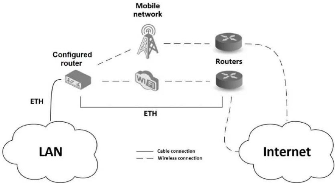
II. Backed up access to the Internet (from LAN)
flowchart
graph TD
    A["LAN"] -->|ETH| B["Configured router"]
    B --> C["Mobile network"]
    C --> D["Routers"]
    D --> E["Internet"]
    style A fill:#f9f,stroke:#333
    style B fill:#ccf,stroke:#333
    style C fill:#cfc,stroke:#333
    style D fill:#fcc,stroke:#333
    style E fill:#cff,stroke:#333
    linkStyle 0 stroke:#000,stroke-width:2px
    linkStyle 1 stroke:#000,stroke-width:2px
    linkStyle 2 stroke:#000,stroke-width:2px
    linkStyle 3 stroke:#000,stroke-width:2px
    linkStyle 4 stroke:#000,stroke-width:2px
    linkStyle 5 stroke:#000,stroke-width:2px
    linkStyle 6 stroke:#000,stroke-width:2px
    linkStyle 7 stroke:#000,stroke-width:2px
    linkStyle 8 stroke:#000,stroke-width:2px
    linkStyle 9 stroke:#000,stroke-width:2px
    linkStyle 10 stroke:#000,stroke-width:2px
    linkStyle 11 stroke:#000,stroke-width:2px
    linkStyle 12 stroke:#000,stroke-width:2px
    linkStyle 13 stroke:#000,stroke-width:2px
    linkStyle 14 stroke:#000,stroke-width:2px
    linkStyle 15 stroke:#000,stroke-width:2px
    linkStyle 16 stroke:#000,stroke-width:2px
    linkStyle 17 stroke:#000,stroke-width:2px
    linkStyle 18 stroke:#000,stroke-width:2px
    linkStyle 19 stroke:#000,stroke-width:2px
    linkStyle 20 stroke:#000,stroke-width:2px
    linkStyle 21 stroke:#000,stroke-width:2px
    linkStyle 22 stroke:#000,stroke-width:2px
    linkStyle 23 stroke:#000,stroke-width:2px
    linkStyle 24 stroke:#000,stroke-width:2px
    linkStyle 25 stroke:#000,stroke-width:2px
    linkStyle 26 stroke:#000,stroke-width:2px
    linkStyle 27 stroke:#000,stroke-width:2px
    linkStyle 28 stroke:#000,stroke-width:2px
    linkStyle 29 stroke:#000,stroke-width:2px
    linkStyle 30 stroke:#000,stroke-width:2px
    linkStyle 31 stroke:#000,stroke-width:2px
    linkStyle 32 stroke:#000,stroke-width:2px
    linkStyle 33 stroke:#000,stroke-width:2px
    linkStyle 34 stroke:#000,stroke-width:2px
    linkStyle 35 stroke:#000,stroke-width:2px
    linkStyle 36 stroke:#000,stroke-width:2px
    linkStyle 37 stroke:#000,stroke-width:2px
    linkStyle 38 stroke:#000,stroke-width:2px
    linkStyle 39 stroke:#000,stroke-width:2px
    linkStyle 40 stroke:#000,stroke-width:2px
    linkStyle 41 stroke:#000,stroke-width:2px
    linkStyle 42 stroke:#000,stroke-width:2px
    linkStyle 43 stroke:#000,stroke-width:2px
    linkStyle 44 stroke:#000,stroke-width:2px
    linkStyle 45 stroke:#000,stroke-width:2px
    linkStyle 46 stroke:#000,stroke-width:2px
    linkStyle 47 stroke:#000,stroke-width:2px
    linkStyle 48 stroke:#000,stroke-width:2px
    linkStyle 49 stroke:#000,stroke-width:2px
    linkStyle 50 stroke:#000,stroke-width:2px
Figure 2: Backed up access to the Internet
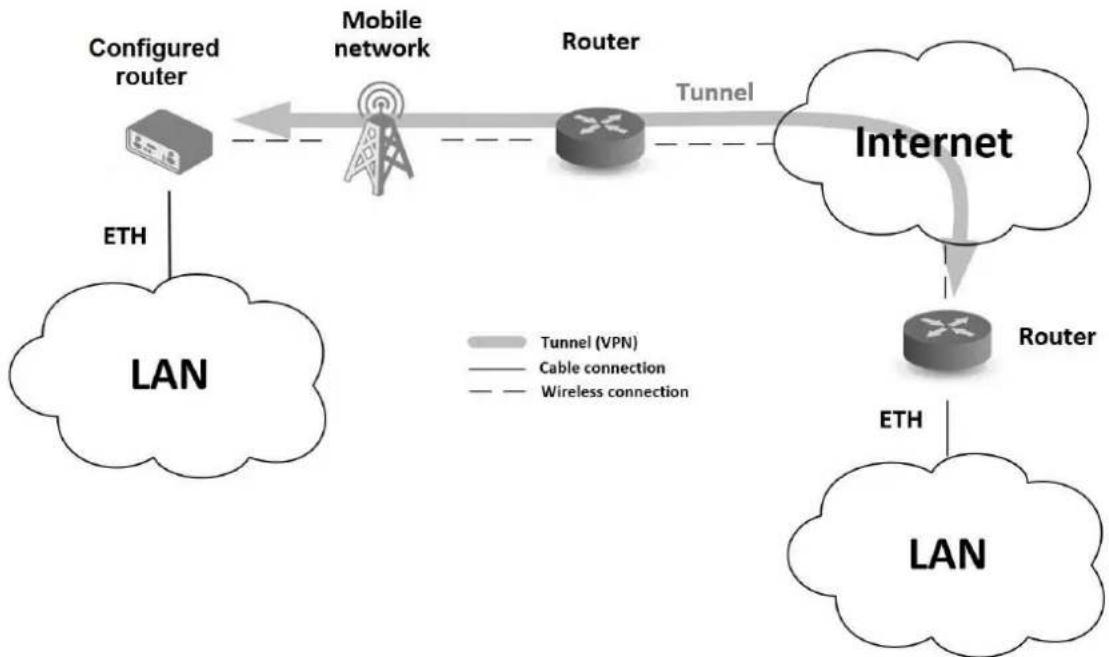
III. Secure networks interconnection or using VPN
flowchart
graph LR
    A["ETH"] --> B["LAN"]
    B --> C["Mobile network"]
    C --> D["Router"]
    D --> E["Tunnel"]
    E --> F["Internet"]
    F --> G["Router"]
    G --> H["ETH"]
    H --> I["LAN"]
    style A fill:#f9f,stroke:#333
    style B fill:#ccf,stroke:#333
    style C fill:#cfc,stroke:#333
    style D fill:#fcc,stroke:#333
    style E fill:#cff,stroke:#333
    style F fill:#ffc,stroke:#333
    style G fill:#cfc,stroke:#333
    style H fill:#fcc,stroke:#333
    style I fill:#cfc,stroke:#333
Figure 3: Using VPN tunnel
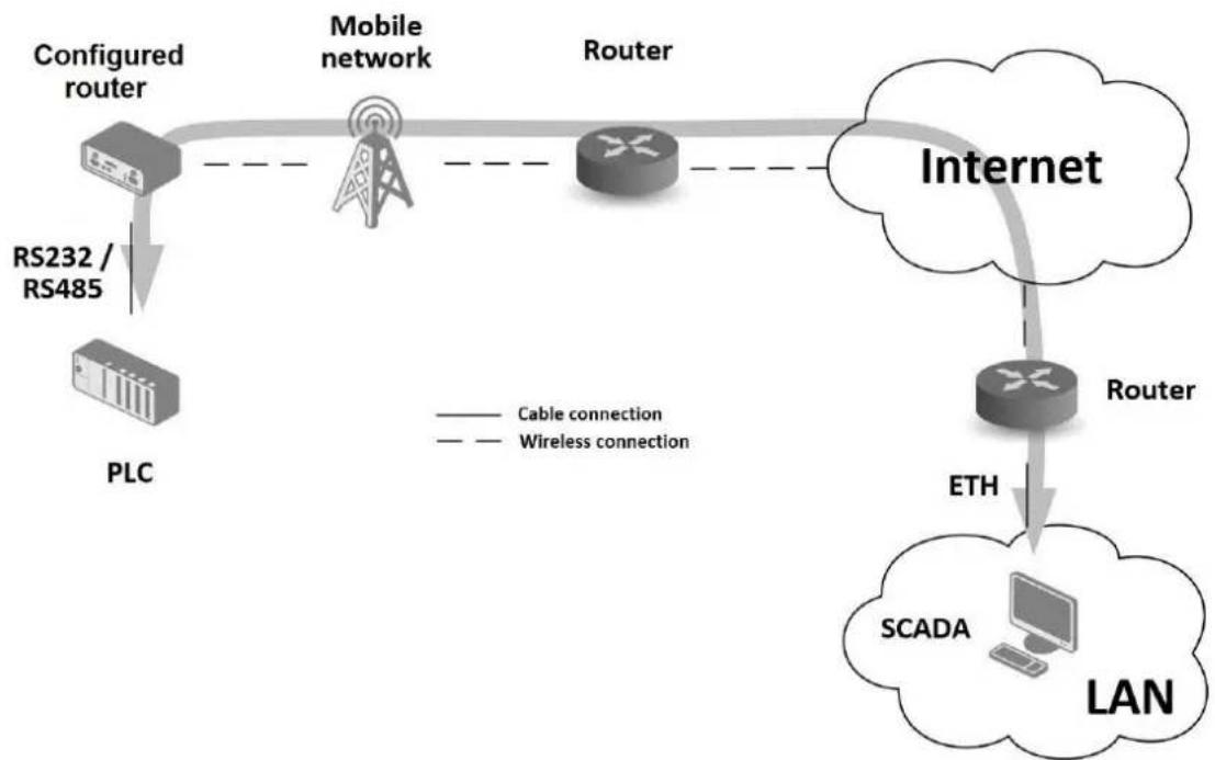
IV. Serial Gateway
flowchart
graph TD
    A["Configured router"] -->|RS232 / RS485| B["Mobile network"]
    B --> C["Router"]
    C --> D["Internet"]
    D --> E["Router"]
    E --> F["SCADA"]
    F --> G["LAN"]
    style A fill:#f9f,stroke:#333
    style B fill:#ccf,stroke:#333
    style C fill:#cfc,stroke:#333
    style D fill:#fcf,stroke:#333
    style E fill:#cff,stroke:#333
    style F fill:#ffc,stroke:#333
    style G fill:#cfc,stroke:#333
    linkStyle 0 stroke:#000,stroke-width:2px
    linkStyle 1 stroke:#000,stroke-width:2px
    linkStyle 2 stroke:#000,stroke-width:2px
    linkStyle 3 stroke:#000,stroke-width:2px
    linkStyle 4 stroke:#000,stroke-width:2px
    linkStyle 5 stroke:#000,stroke-width:2px
    linkStyle 6 stroke:#000,stroke-width:2px
    linkStyle 7 stroke:#000,stroke-width:2px
    linkStyle 8 stroke:#000,stroke-width:2px
    linkStyle 9 stroke:#000,stroke-width:2px
    linkStyle 10 stroke:#000,stroke-width:2px
Figure 4: Serial Gateway
4. Contents of Package

Basic delivered set of router includes:
- router,
- power supply,
• crossover UTP cable, - up to three external antennas,
- loose power and I/O connector (+8 pins ^1 ),
- 4-pins and 5-pins terminal block for RS485 and RS232 (only for version with interface RS232-RS485/422),
- 3-pins and 4-pins terminal block for RS485 and RS232 (only for version with interface RS232-RS485-ETH),
- clip for the DIN rail,
• printed Quick Start Guide Leaflet.

natural_image
Product photo of SmartFlex network equipment including ports, connectors, and charging cables (no visible text or symbols)Figure 5: Contents of package

Temperature range for power supply is reduced to 0 °C to +40 °C!
5. Router Design
5.1 Router versions

Check with your local Advantech sales representative for available options and HW configurations.
SmartFlex SR304 router is supplied in the following versions (see table below). All versions are available in plastic or metal box according to customer requirements. All versions are available with PoE PD (Power over Ethernet – powered device) so you can power the router from both ETH0 and ETH1 interfaces, or with PoE PSE (power source equipment) so you can power other devices by the router.
| Router versions | SIM | BIN | BOUT | USB | SD | ETH | WiFi | 232 | 485 |
| Basic version 2 x 2 x 1 x 1 x 1 x 2 x | |||||||||
| Basic version with WiFi 2 x 2 x 1 x 1 x 1 x 2 x 1 x | |||||||||
| Version with SWITCH board 2 x 2 x 1 x 1 x 1 x 5 x | |||||||||
| Version with SWITCH board & WiFi | 2x | 2x | 1x | 1x | 1x | 5x | 1x | ||
| Version with RS232-RS485/422 board | 2x | 2x | 1x | 1x | 1x | 2x | 1x | 1x | |
| Version with RS232-RS485/422 & WiFi | 2x | 2x | 1x | 1x | 1x | 2x | 1x | 1x | 1x |
| Version with RS232-RS485-ETH board | 2x | 2x | 1x | 1x | 1x | 3x | 1x | 1x | |
| Version with RS232-RS485-ETH & WiFi | 2x | 2x | 1x | 1x | 1x | 3x | 1x | 1x | 1x |
| Version with RS485-RS485 | 2x | 2x | 1x | 1x | 1x | 2x | 2x |
Table 1: Router versions
text_image
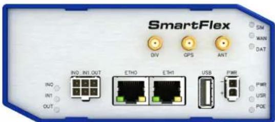
SmartFlex INV_INI_OUT INO INT OUT DIV GPS ANT ETH0 ETH1 USB PWR SM WAN DAT PWR USR POEFigure 6: Basic version (plastic)
text_image
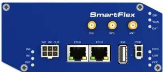
SmartFlex SIM WAN DAT DIN GPS ANT IN0 IN1 OUT ETH0 ETH1 USB PWR IN1 OUT PWR USR POEFigure 8: Basic version (metal)

text_image
SmartFlex DIV GPS ANT SM WAN DAT INIO INI OUT IND INT OUT ETHO ETH1 USB PWR PWR USR POEFigure 7: Basic version with WiFi (plastic)

text_image
SmartFlex SIM WAN DAT DIV GPS ANT WIFI IND INT OUT IND IN1 OUT ETH0 ETH1 USB PWR PWR USR POEFigure 9: Basic version with WiFi (metal)

text_image
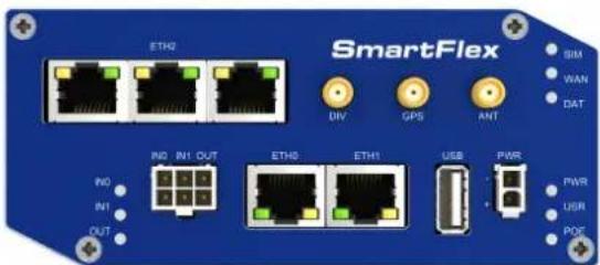
ETH2 SmartFlex DIV GPS ANT SIM WAN DAT IN0 IN1 OUT ETH0 ETH1 USB PWR IN1 OUT PWR USR POEFigure 10: Version SWITCH (plastic)
text_image
SmartFlex ETH0 DIV GPS ANT SIM WAN DAT NO IN1 OUT INT ETH0 ETH1 USB PWR PWR USR PDFFigure 15: Version SWITCH (metal)
text_image
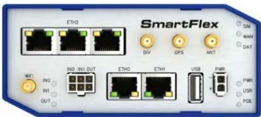
SmartFlex ETHQ DIV GPS ANT SIM WAN DAT IN0 IN1 OUT ETHO ETH1 USB PWR PWR USR PDE WFT IN0 IN1 OUTFigure 11: Version SWITCH and WiFi (plastic)
text_image
SmartFlex ETHQ DIV GPS ANT SIM WAN DAT MOD INT OUT ETHS ETH1 USB PWR NO INT OUT PWR USR ROEFigure 16: Version SWITCH and WiFi (metal)
text_image
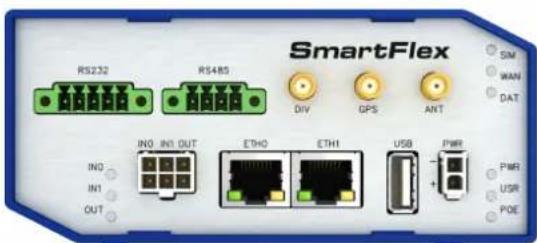
SmartFlex RS232 RS485 INV IN1 OUT ETHO ETH1 USB PWR SM WAN DAT IN1 OUT IN0 OUT PWR USR POEFigure 12: Version RS232-RS485 (plastic)

text_image
SmartFlex RS232 RS485 DIV GPS ANT SIM WAN DAT NO IN1 OUT ETH0 ETH1 USB PWR IN1 OUT PWR USR POEFigure 17: Version RS232-RS485 (metal)

text_image
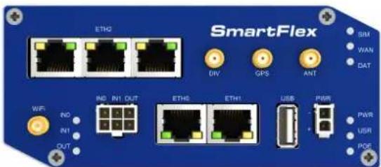
SmartFlex RS232 RS485 DV GPS ANT SIM WAN DAT WIFI INO INI OUT ETHO ETH1 USB PWR PWR USR PDE INI OUTFigure 13: Ver. RS232-RS485 & WiFi (plastic)

text_image
SmartFlex RS232 RS485 DIV GPS ANT SIM WAN DAT WIFI IN0 IN1 OUT ETH0 ETH1 USB PWR IN1 OUT OUTFigure 18: Version RS232-RS485 & WiFi (metal)
text_image
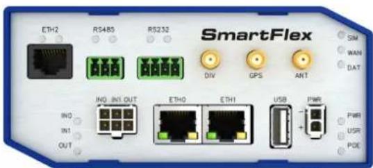
ETH2 RS485 RS233 SmartFlex DIV GPS ANT SIM WAN DAT ING IN1 OUT ETH0 ETH1 USB PWR IN1 OUT PWR USR POEFigure 14: Version RS232-RS485-ETH (plastic)

text_image
ETH2 RS485 RS232 SmartFlex SIM WAN DAT DIV GPS ANT IN0 IN1 OUT ETH0 ETH1 USB PWR IN1 OUT PWR USR POEFigure 19: Version RS232-RS485-ETH (metal)
text_image
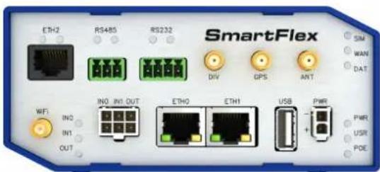
SmartFlex ETH2 RS485 RS232 DIV GPS ANT SM WAN DAT WIFI IN0 IN1 OUT ETHO ETH1 USB PWR IN1 OUT PWR USR POEFigure 20: RS232-RS485-ETH & WiFi (plastic)
text_image
ETH2 RS485 RS232 SmartFlex SIM WAN DAT DIV GPS ANT ING IN1 OUT ETH0 ETH1 USB PWR PWR USR POEFigure 21: RS232-RS485-ETH & WiFi (metal)

text_image
SmartFlex RS485 RS485 INV IN1 OUT ETH0 ETH1 USB PWR INS IN1 OUT SIM WAN DAT PWM USK POEFigure 22: RS485-RS485 (metal)
5.2 Product Revisions
For the product revision history, see the table below. The revision number is printed on the packaging and product labels.
The router GUI can also display the product revision under Status -> General -> System Information -> Product Revision. Please note that the default revision (Rev.1.0) is unavailable here.
| Rev.# | Description |
| 1.0 | Initial version (revision not printed on the labels). |
| 2.0 | New SIM slot type; see PCN-2022-03 for details. |
Table 2: HW Revisions History
5.3 Delivery identification
| Trade name Product name Description | ||
| SmartFlex SR304 | SmartFlex | Router in a plastic or metal box |
Table 3: Delivery identification

text_image
SmartFlex Industrial Cellular Router 10-60V---1.1A MAX P/N: BB-SR30400010 Rev.2.0 S/N: ACZ1100123456785 MAC: 01:23:45:67:89:AB IMEI: 123456789012345 Advantech Czech s.r.o., Sokolska 71 56204 Usti nad Orlici, Czech Republic Def. password: P23456785h
text_image
UL CERTIFIED E487720 Info. Tech. Equip.Figure 23: Label examples
5.4 Order codes
Order codes overview is shown in the table below.
| Product Name | Order code | Features – interfaces |
| SR304 BB-SR3040x0yz | * | LTE module for EMEA, 2x ETH, 1x USB, 2x BI, 1x BO, 1x microSD reader, 2x SIM reader |
| SR304 BB-SR3041x0yz | * | LTE module for EMEA, 2x ETH, 1x USB, 2x BI, 1x BO, 1x microSD reader, 2x SIM reader, WiFi |
| SR304 BB-SR3040x1yz | * | LTE module for EMEA, 5x ETH, 1x USB, 2x BI, 1x BO, 1x microSD reader, 2x SIM reader |
| SR304 BB-SR3041x1yz | * | LTE module for EMEA, 5x ETH, 1x USB, 2x BI, 1x BO, 1x microSD reader, 2x SIM reader, WiFi |
| SR304 BB-SR3040x3yz | * | LTE module for EMEA, 2x ETH, 1x USB, 2x BI, 1x BO, 1x microSD reader, 2x SIM reader, RS232, RS485 |
| SR304 BB-SR3041x3yz | * | LTE module for EMEA, 2x ETH, 1x USB, 2x BI, 1x BO, 1x microSD reader, 2x SIM reader, WiFi, RS232, RS485 |
| SR304 BB-SR3040x4yz | * | LTE module for EMEA, 3x ETH, 1x USB, 2x BI, 1x BO, 1x microSD reader, 2x SIM reader, RS232, RS485 |
| SR304 BB-SR3041x4yz | * | LTE module for EMEA, 3x ETH, 1x USB, 2x BI, 1x BO, 1x microSD reader, 2x SIM reader, WiFi, RS232, RS485 |
| SR304 BB-SR3040x6yz | * | LTE module for EMEA, 2x ETH, 1x USB, 2x BI, 1x BO, 1x microSD reader, 2x SIM reader, 2x RS485 |
Table 4: Order codes overview

* Replace the letters "x", "y" and "z" with the values from the following tables:
Letter "x" – Power over Ethernet (PoE)
| Power over Ethernet (PoE) | Number "x" in code |
| Version without PoE 0 | |
| PoE PSE – Power Source Equipment – powers other devices | 8 |
| PoE PD – Powered Device – can be powered via Ethernet | 9 |
Table 5: Power over Ethernet
Letter "y" – type of the router box
| Type of box | Number "y" in code |
| Plastic 1 | |
| Metal 2 |
Table 6: Type of router box
Letter "z" – type of the power supply connector
| Type of power supply | Number "z" in code |
| Without accessories 0 | |
| European 1 | |
| Interchangeable plug adapters (EU, US, UK, AUS) | 5 |
Table 7: Type of power supply
Examples of complete order code:
| Order code Features – interfaces Box Power | supply | ||
| BB-SR30408011 | LTE module for EMEA, 2x ETH, 1x USB, 2x BI, 1x BO, 1x microSD reader, 2x SIM reader, PoE PSE | plastic | Europe |
| BB-SR30409121 | LTE module for EMEA, 5x ETH, 1x USB, 2x BI, 1x BO, 1x microSD reader, 2x SIM reader, PoE PD | metal | Europe |
| BB-SR30400410 | LTE module for EMEA, 3x ETH, 1x USB, 2x BI, 1x BO, 1x microSD reader, 2x SIM reader, RS232, RS485 | plastic | None |
| BB-SR30410320 | LTE module for EMEA, 2x ETH, 1x USB, 2x BI, 1x BO, 1x microSD reader, 2x SIM reader, WiFi, RS232, RS485 | metal | None |
Table 8: Examples of order code
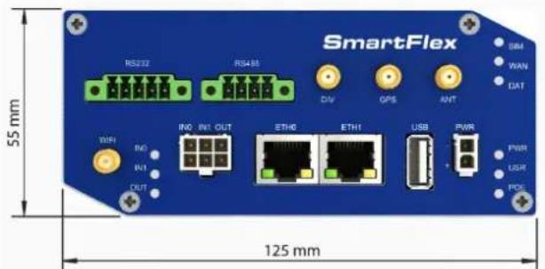
5.5 Basic dimensions of the router box
text_image
SmartFlex RS222 RS488 55 mm INIO INI OUT ETH0 ETH1 USB PWR OUT DRM WAN DAT PWM USR PDE 125 mm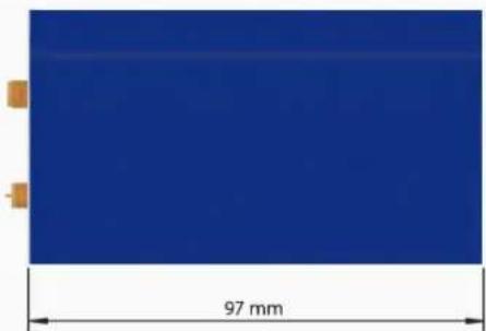
natural_image
Blue rectangular object with a 97 mm dimension label, no other text or symbols visibleFigure 24: Basic dimensions of the router box
5.6 Mounting Recommendations
- It is possible to place the router on a flat surface,
• DIN rail EN 60715 with the included plastic or metal clip.
For most applications with a built-in router within a switchboard, it is possible to recognize two kinds of environments:
- A non-public, industry environment of low voltage with high interference,
- a public environment of low voltage and without high interference.
For both of these environments, it is possible to mount the router to a switchboard, after which there is no need to have examination immunity or issues in connection with EMC according to EN 61439-1:2011.

In compliance with the EN 61439-1:2011 specification, it is necessary to observe the following assembly instructions for a router attached to a switchboard:
- For whip antennas it is recommended to observe a minimum distance of 6 cm from cables and metal surfaces on every side in order to avoid interference. When using an external antenna separate from the switchboard it is necessary to fit a lightning conductor.
- When mounting a router on sheet-steel we recommend using a cable antenna.
- For all cables, we recommend to bind the bunch, and for this we recommend:
- The length of the bunch (the combination of power supply and data cables) should be a maximum 1.5 m. If the length of data cables exceeds 1.5 m or if the cable is leading towards the switchboard, we recommend installing surge protectors.
- Data cables must not have a reticular tension of 230 V/50 Hz or 120 V/60 Hz.
- Sufficient space must be left between each connector for the handling of cables,
• To ensure the correct functioning of the router we recommend the use of an earth-bonding distribution frame for the grounding of the power supply of the router, data cables and antenna within the switchboard.
5.7 Removal from the DIN rail

The DIN rail clip is suitable for a DIN rail according to EN 60715 standard only. The default position of plastic or metal rail clip, which is used for mounting the router on a DIN rail, is shown in the following figure. Its position can be changed on some models (back or bottom). When changing the position of the DIN rail clip, tighten the screws with max. 0.4 Nm torque.

natural_image
Metallic electronic component with four mounting holes and a rectangular slot (no text or symbols)
natural_image
White plastic mechanical component with mounting holes and a roller (no text or symbols visible)Figure 25: Default position of plastic and metal DIN rail clip
To remove the router from the DIN rail, push the router down lightly, so the bottom part of the DIN rail clip (hitched to the DIN rail) gets out of the rail and then pull out the bottom part of the router away from the DIN rail.

text_image
DIN rail Router 1. 2. 3.Figure 26: Removal from the DIN rail
5.8 Description of the rear panel
The rear panel contains two holders for SIM cards (SIM1 and SIM2), a holder for microSD card (SD) and an RST button used to restore the default configuration and reboot the router.
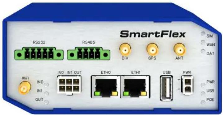
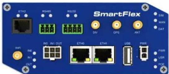
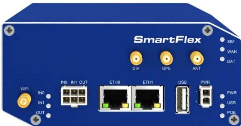
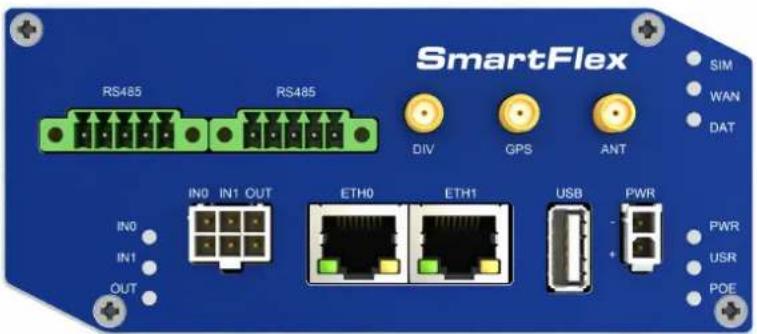
5.9 Description of the front panel
On the front panel is the following:
| Caption Connector Description | ||
| PWR | 2-pin | Connector for the power supply |
| ETH0 RJ45 | Connector for connection into the computer network, PoE (only for PoE PSE or PoE PD versions) | |
| ETH1 RJ45 | Connector for connection into the computer network, PoE (only for PoE PSE or PoE PD versions) | |
| ANT SMA | Connector for main antenna | |
| DIV SMA | Connector for diversity antenna | |
| GPS SMA | Connector for GPS antenna | |
| WiFi | R-SMA | Connector for WiFi antenna (only for versions with WiFi module!) |
| USB | USB-A 2.0 Host | Connector for connection of USB devices to the router. Supports devices with PL-2303 and FTDI USB/RS232 converters. |
| I/O | 6-pin | Connector for connection of the binary inputs and output |
Table 9: Front panel description
text_image
SmartFlex DIV GPS ANT SIM WAN DAT IN0 IN1 OUT ETH0 ETH1 USB PWR PWR USR POE WIFI IN0 IN1 OUTFigure 27: SmartFlex front panel
5.9.1 Status indication
There are status LEDs on the front panel to provide router status information. Each ETH port has two additional LEDs that provide information about the port status.
| Caption Color State | Description | ||
| PWR Green Blinking | OnFast blinking | The router is booting up.The router booted up and is ready.The router firmware is being updated. | |
| USR | Yellow | — | The function of this LED is user-defined. |
| POE Yellow | Green | OnBlinkingOnBlinkingOff | PSE: The insufficient voltage on the PWR connector.PSE: The powered device takes too much power. ^1 PD: The power supply is present on an ETH port.PSE: A correct power supply on the PWR connector.PSE: A device is powered via one of the ETH ports.PD: The power supply is not present on an ETH port.PSE: The PoE disabled in the Ethernet configuration. |
| SIM Green | Yellow | On (Green color)On (Yellow color) | The first SIM card is active.The second SIM card is active. |
| WAN | Yellow | Fades out 1x/5 sFades out 1x/2 sFades out 1x/1 s | Signal strength is good.Signal strength is fair ^2 .Signal strength is poor ^3 .For value ranges of signal strength seeConfiguration manual, chapterMobile WAN Status. |
| DAT | Red | Blinking | Cellular communication is in progress. |
| IN0 | Green | On | The first binary input is active. |
| IN1 | Green | On | The second binary input is active. |
| OUT | Yellow | On | The binary output is active. |
| ETH0ETH1 | Green On | Off | Selected 100 Mbps.Selected 10 Mbps. |
| ETH0ETH1 | Yellow On | BlinkingOff | The network cable is connected.Data transmission.The network cable is not connected. |
Table 10: LED status indication

The status indication of the WAN LED is updated every 10 seconds.
5.9.2 Power connector PWR
Panel socket 2-pin.
| Pin number S | gnal mark Description | |
| 1 | GND(-) | Negative pole of DC supply voltage |
| 2 | VCC(+) | Positive pole of DC supply voltage (+10 to +60 V DC) |
Table 11: Connection of power connector

Figure 28: Power connector

Unit has to be supplied by a power supply specified as a Limited Power Source (LPS) according to Annex Q of IEC 62368-1. If the power supply/cable provided with device is not used, always use the cables with minimum wire size (nominal cross section) 0.5 square mm for power supply.
The power supply for the router must be between +10 V to +60 V DC supply. Protection against reversed polarity without signaling is built into the router. Note: The protection against reversed polarity is lost if the negative pole is grounded!

Circuit example:
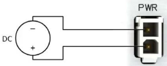
text_image
DC - + PWRFigure 29: Connection of power supply

Note for PoE: See Chapter 5.9.7 for information on how PoE versions of the router impact the power supply usage. The power supply for a PoE router has to meet other specific requirements.

All metal parts are connected together with the negative pole of power supply (common pole).
Low Power Mode

In applications requiring low power consumption (such as solar power - not 7/24 mode) is strictly recommended to use LPM mode prior to powering down the entire router.
LPM (Low Power Mode) is a router mode where the router is in sleep mode with minimal power consumption. The router can be woken up from this mode by a signal applied to the BIN1 input or after a predetermined period of time. Putting the router into LPM mode can be done using the 1pm command, see Commands and Scripts application note for more details. Consumption in LPM mode may vary depending on the configuration of the router.
5.9.3 Antenna connector ANT, DIV, GPS and WiFi
The main, diversity and GPS antennas are connected to the router using the SMA connector on the front panel. There is also an R-SMA antenna connector available, through which an additional antenna can be connected, if the router is equipped with a WiFi module.
The ANT connector is used to First, connect the main antenna to the router. To connect the diversity antenna, the second antenna connector DIV is used. The third connector (GPS) is intended for a GPS antenna (the router supports active GPS antennas). An R-SMA connector named WiFi is designed for the connection of a WiFi antenna (available only for versions with a WiFi module).
!
The router can not operate without a main antenna connected through the port marked as ANT!
i
The DIV celular antenna is required for the MIMO DL functionality.
i
An SMA connector is used for the connection of the antenna. The antenna is connected by screwing this antenna to the SMA connector on the router's front panel (see the figure below).
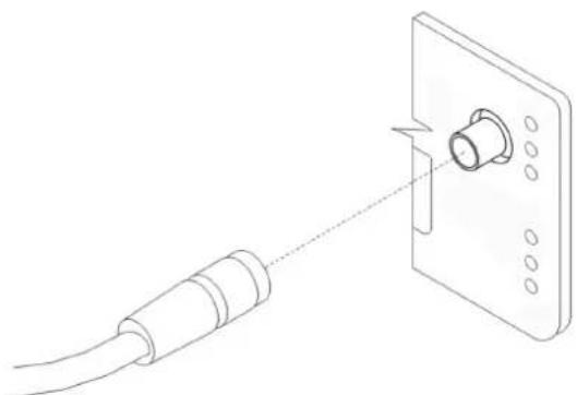
natural_image
Line drawing of a cable being inserted into a wall-mounted device (no text or symbols)Figure 30: Connecting the antenna
i
A diversity antenna improves the radio capability of the router at low signal strength.
5.9.4 SIM card reader
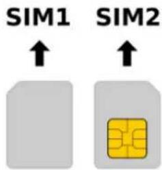
Two SIM card readers for 3 V and 1.8 V SIM cards are located on the rear panel of the router. In order for the router to function, it is necessary to insert an activated SIM card with an unblocked PIN code. The SIM cards may have different APNs (Access Point Names) adjusted.

Supported type of SIM cards: Mini SIM (2FF), dimensions 25.0 x 15.0 x 0.76 mm.
Changing the SIM card:
• Always disconnect the router from the power supply before handling the SIM card.
- To remove the SIM card, use the flat end of a spudger, or your fingernail, press the SIM card slightly into its slot until you hear a click.
• After hearing this click, release the card, and it will pop out of its slot.
- Remove the SIM card and push any other SIM card into the slot until it clicks into place.
text_image
SIM1 ↑ SIM2 ↑
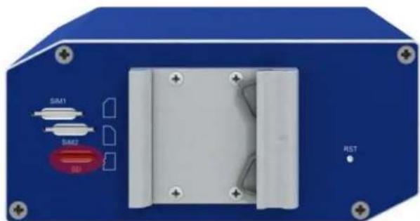
natural_image
Blue electronic device rear panel with indicator lights (SIM1, SIM2, SD) and a white internal component, no visible text or symbols beyond labels.Figure 31: SIM cards
5.9.5 MicroSD card reader
The microSD card reader is located on the router's rear panel (the third slot). This card reader allows the router to operate with microSD memory cards. The technical specifications are stated in the table below. The microSD card changing procedure is described below.
| Technical specifications of microSD card | ||
| Supported technologies SDHC, SDXC | ||
| Supported capacity SDHC | SDXC | up to 32 GBfrom 32 GB to 64 GB |
| Supported microSD card filesystems | vfat, ext2, ext3, ext4 | |
Table 12: Technical specifications of microSD card
Changing the microSD card:
- To remove the microSD card, use the flat end of a spudger, or your fingernail, press the microSD card slightly into its slot until you hear a click.
• After hearing this click, release the card, and it will pop out of its slot. - Remove the microSD card and push any other microSD card into the slot until it clicks into place.

natural_image
Blue electronic device back panel with white components and red indicator lights (no visible text or symbols)Figure 32: MicroSD card
Mounting microSD Card to the System
It is necessary to mount the microSD card to be able to access it in the system of the router. Follow these steps to mount the card:
- Use the dmesg command to see the list of recently connected devices.
- In the output of the command find out the entry for the microSD card, for example: mmcblk0: p1
- To mount the card to to mnt directory, use the mount command: mount /dev/mmcblk0p1 /mnt

For more information about the commands for creating, mounting, checking and unmounting a file system on a microSD card, see the application note for Ext4_tools router app.
5.9.6 Ethernet Ports (ETH0 and ETH1)
The panel socket RJ45 is used for this interface. The isolation barrier of the Ethernet signal ports against the ground is 1500 V.
| Pin | 10base-T & 100base-T | PoE (Mode B) |
| 1 Tx+ (Transmit Data+) — | ||
| 2 Tx- (Transmit Data-) — | ||
| 3 Rx+ (Receive Data+) — | ||
| 4 — PoE + (positive pole) | ||
| 5 — PoE + (positive pole) | ||
| 6 Rx- (Receive Data-) — | ||
| 7 — PoE - (negative pole) | ||
| 8 — PoE - (negative pole) | ||
Table 13: Ethernet connector pinout

Figure 33: Ethernet connector
The crossover UTP cable (Ethernet cable) plugs into the RJ45 connector labeled as ETH0 or ETH1 (see the figure below).

natural_image
Diagram of a cable connector inserted into a wall-mounted socket (no text or symbols)Figure 34: Connection of Ethernet cable

The insulation strength of Ethernet ports from each other and from the rest of the router (grounding) is dependent on the router version:
| Router Version | Insul. Strength from Router | Insul. Strength between Ports |
| Without PoE | 1.5 kV | 1.5 kV |
| PoE PD | 1.5 kV | none |
| PoE PSE | none | none |
Table 14: Insulation strength of Ethernet ports
5.9.7 Power over Ethernet (PoE)
Available only for models with PoE feature; see Chapter 5.4 for the order codes.
You can not power the router via the ETH2 ports on the SWITCH router version. The PoE PD is available on the ETH0 and ETH1 ports only.
The IEEE 802.3af/PoE (Type 1) and IEEE 802.3at/PoE+ (Type 2) standards are supported. The device is Mode B compliant.
You can use thepse command to control the PoE functionality; see the Commands and Scripts application note.
Based on the model configuration, the PoE PSE or PoE PD feature can be supported for both Ethernet ports (ETH0 and ETH1).
The PoE PSE version allows the router to power other devices over the Ethernet. The PoE PD version enables the router to be powered by another PoE PSE device over the Ethernet.
PoE PD

flowchart
graph LR
    A["Power supply"] --> B["Power source equipment"]
    B --> C["Powered device"]
    C --> D["Internet"]
    D --> E["SCADA/FTP"]
    B --> F["Advantech router"]
Figure 35: PoE PD usage
The PoE PD parameters can be found in Chapter 7.8. The POE LED on the front panel of the router lights up green when voltage is present on an Ethernet port, so the user knows the router can be PoE powered. You can still power the router with this connector even if the router is powered with PoE (in PoE PD version), but the input voltage must be higher than 15 V DC. If the input voltage is lower than 15 V DC and the PoE voltage is present (POE LED green on), the router will still be powered from the Ethernet connector via PoE.
PoE PSE

flowchart
graph TD
    A["Powered devices"] --> B["Power source equipment"]
    C["Powered devices"] --> B
    D["Power supply"] --> E["Advantech router"]
    B --> F["Internet"]
    E --> F
    G["SCADA/FTP"] --> F
Figure 36: PoE PSE usage

The power supply used with the PoE PSE router has to provide voltage from 44 to 57 V DC and the output power has to be at least 65 W for full PoE+ use (Class 4) in both Ethernet ports (ETH0 and ETH1).
The PoE PSE parameters can be found in Chapter 7.8. The PoE state is indicated by the POE LED on the front panel of the router, see Chap. 5.9.1. When sufficient voltage (44 to 57 V) and power is available is indicated by the green light. A yellow POE LED indicates insufficient power or voltage through the PWR connector. When a device is being powered from the router, the POE LED will be blinking green. Yellow blinking is shown for an overload (the powered device is using too much power) or a short circuit (incorrect wiring of the cable or of the device without PoE support).
You can enable or disable the PoE PSE feature separately on the ETH0 and ETH1 ports via the Web interface of the router. This can be found in the LAN configuration pages (Primary for ETH0, Secondary for ETH1). When PoE PSE is enabled, you can find the current, voltage, power and power class information on the General page of the router's Web interface; see the Configuration manual [1].
5.9.8 USB Port
Panel socket USB-A.
| Pin | Signal mark | Description Data flow direction | |
| 1 | +5 V | Positive pole of 5 V DC supply voltage, 0.5 A | |
| 2 | USB data - | USB data signal – negative pole | Input/Output |
| 3 | USB data + | USB data signal – positive pole | Input/Output |
| 4 | GND | Negative pole of DC supply voltage |
Table 15: Connection of USB connector

Figure 37: USB connector

The USB port is disabled on overload to prevent its damage (connected device is trying to get too high current). The port is enabled again after the reboot of the router.
Mounting USB Flash Drive to the System
It is necessary to mount the USB flash drive to be able to access it in the system of the router. Follow these steps to mount the drive:
- Use the dmesg command to see the list of recently connected devices.
- In the output of the command find out the entry for the microSD card, for example: sda: sda1
- To mount the card to to mnt directory, use the mount command: mount /dev/sda1 /mnt

For more information about the commands for creating, mounting, checking and unmounting a file system on a USB Flash Drive, see the application note for Ext4_tools router app.
5.9.9 I/O Port
Panel socket 6-pin.
| Pin Signal mark Description | ||
| 1 IN0 | Binary input 0 | |
| 2 IN0 | Binary input 0 | |
| 3 IN1 | Binary input 1 | |
| 4 IN1 | Binary input 1 | |
| 5 OUT | Binary output | |
| 6 OUT | Binary output | |
Table 16: Connection of I/O port

text_image
1 3 5 2 4 6Figure 38: I/O connector
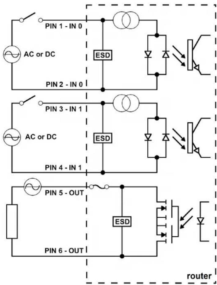
The I/O user Interface is designed for the processing of binary input and control (setting) of binary output. Binary output is open in the default configuration. The isolation strength is 1.5 kV. The pins are isolated from each other with the same strength.
The input circuits are bipolar and allow connection as needed with common plus or minus (according to the connection of an external voltage).
Binary inputs
- Characteristics of inputs:
| Logical 0 / 1* | Voltage Current Web interface status | ||
| log. 1 max | 3 V | 0.4 mA | Off |
| log. 0 min | 5 V | 0.7 mA | On |
| log. 0 type | 12 V | 2 mA | On |
| log. 0 max | 60 V | 7 mA | On |
Table 17: Characteristics of inputs
* The binary input status in the Shell is returned via io get bin0 or io get bin1.
Binary output
• Binary output parameters:
-60 V AC / 300 mA
-60 V DC / 300 mA
- The current of the binary output is limited by a resettable fuse (300 mA).
Binary inputs and output connections
Binary inputs and output connections example:
flowchart
graph TD
    subgraph Top_Day
        A["AC or DC"] --> B["PIN 1 - IN 0"]
        B --> C["ESD"]
        C --> D["Pin 2 - IN 0"]
    end
    subgraph Bottom_Day
        E["AC or DC"] --> F["PIN 3 - IN 1"]
        F --> G["ESD"]
        G --> H["Pin 4 - IN 1"]
    end
    subgraph Router
        I["PIN 5 - OUT"] --> J["ESD"]
        J --> K["Pin 6 - OUT"]
    end
    style Top_Day fill:#f9f,stroke:#333
    style Bottom_Day fill:#bbf,stroke:#333
Figure 39: Binary connection
5.9.10 Reset
When the PWR LED starts flashing on the front panel, it is possible to restore the default configuration of the router by pressing the RST button on the rear panel. After pressing this button the default configuration will be restored and the router will reboot (after which the green LED will be on).

It is necessary to use a narrow screwdriver or any other small tool to press the RST button.

natural_image
Blue industrial device with internal components and a screwdriver, no visible text or symbolsFigure 40: Router reset

Before resetting the router, it is recommended to back up the router configuration settings (see Configuration manual) because resetting the router will return all configuration settings to their default states.
It is important to distinguish between the router reset and reboot.
| Action R | Router behavior Invoking events | |
| Reboot | Turns off and then turns on the router | Disconnect and reconnect the power, press the Reboot button in the web configuration |
| Reset | Restores the default configuration and reboots the router | Press the RST button |
Table 18: Description of router reset and restart
5.10 Interfaces Description
Besides the basic version of SmartFlex router there are available versions with one of the following interfaces:
- SWITCH interface
• RS232-RS485/422 interface
• RS232-RS485-ETH interface
• RS485-RS485 interface

Note that only the Advantech service center can do the jumpering inside the router.
5.10.1 SWITCH interface
The three LAN ports of the SWITCH interface for SmartFlex routers (RJ45 connectors for connecting Ethernet devices) act as a typical switch device. This means that the router reads Ethernet frames (data packets on an Ethernet link) from any port on the SWITCH interface and transmits them on other ports of the SWITCH interface. Each port can transmit frames independently on the other ports. State indication is displayed separately on each connector. These router versions comply with the standards and temperature ranges stated in Chap. 7.1 except for having a lower maximum operating temperature, which is +70 °C.

text_image
SmartFlex ETH2 DIV GPS ANT SIM WAN DAT IN0 IN1 OUT ETH0 ETH1 USB PWR IN0 IN1 IN1 OUT PWR USR POEFigure 41: Version with SWITCH board
State indication of the interface:
| Description of indication | ||
| Green LED On | Off | Selected 100 MbpsSelected 10 Mbps |
| Yellow LED On | BlinkingOff | The network cable is connectedData transmissionThe network cable is not connected |
Table 19: State indication of the SWITCH interface
Technical specification of Ethernet IEEE 802.3:
| Ethernet interface, IEEE 802.3 standard | |
| Maximum data rate 100 Mbps | |
| Max. total cable length (300 Bd, 200 nF/km) | 100 m |
Table 20: SWITCH interface parameters
5.10.2 RS232-RS485/422 interface
These interfaces are physically connected through the 5-pin and 4-pin terminal block connectors. The insulation strength is up to 2.5kV . Attention, connectors are not isolated from each other! No state indication is displayed for this interface. These router versions comply with the standards and temperature ranges stated in Chap. 7.1.

text_image
SmartFlex RS232 RS485 DIV GPS ANT SIM WAN DAT IN0 IN1 OUT ETH0 ETH1 USB PWR IN0 IN1 OUT IN1 OUT PWR USR POEFigure 42: Version with RS232-RS485/422 interface

When connecting counterpart terminal block connectors (included in package with the router), use cables with nominal cross section 0.2 to 1.0 square mm (30 to 16 AWG). Recommended stripping length is 5 mm. For M2 captive screws the screw driver 0.5 x 3 mm is recommended. Tighten the screws with 0.3 Nm torque.
Connection of RS232 connector:
| Pin Signal Description Direction | |||
| 1 CTS Clear To Send Output | |||
| 2 | RTS | Request To Send | Input |
| 3 GND | Signal ground * | — | |
| 4 RXD | Receive Data | Input | |
| 5 TXD Transmit Data | Output | ||
Table 21: Connection of RS232 connector
* Both connectors (RS232 and RS485/422) have a common ground connection.

Figure 43: RS232 connector
Connection of RS485 connector:
| Pin Signal Description Direction | |
| 1 TxRx+ RS485 B (+) Input/Output | |
| 2 TxRx- RS485 A (-) Input/Output | |
| 3 TxRx+ RS485 B (+) Input/Output | |
| 4 TxRx- RS485 A (-) Input/Output |
Table 22: Connection of RS485 connector

The termination resistor can be activated directly on the port board using a jumper (termination resistor is part of the port board).
Connection of RS422 connector:
| Pin Signal Description Direction | ||
| 1 RxD+ RS422 (+) Output | ||
| 2 RxD- | RS422 (-) | Output |
| 3 TxD+ | RS422 (+) Input | |
| 4 TxD- | RS422 (-) | Input |
Table 23: Connection of RS422 connector

Figure 44: RS485/422 connector
The selection of either RS485 or RS422 can be performed by using jumpers on the board. Three jumpers are required for the RS485 interface or one jumper for the RS422 interface. The default configuration is RS485 with termination off.
Technical specification of RS232 and RS485 bus:
| RS232 and RS485 interface | |
| Max. operating RS232 bus current | 15 mA |
| Max. number of devices on RS485 bus | 32 |
| Max. output current on RS485 bus | 60 mA |
| Max. data rate | 230400 bps on RS232230400 bps on RS485 |
| Max. total cable length (300 Bd, 200 nF/km) | RS232 20 m, RS485 1200 m |
Table 24: Technical specification of RS232 and RS485
5.10.3 RS485-RS485 interface
These interfaces are physically connected through the 5-pin and 5-pin terminal block connectors. The insulation strength is up to 2.5kV . Attention, connectors are not isolated from each other! No state indication is displayed for this interface. These router versions comply with the standards and temperature ranges stated in Chap. 7.1.
text_image
SmartFlex RS485 RS485 DIV GPS ANT SIM WAN DAT IN0 IN1 OUT ETH0 ETH1 USB PWR IN0 IN1 OUT PWR USR POEFigure 45: Version with RS485-RS485 interface

When connecting counterpart terminal block connectors (included in package with the router), use cables with nominal cross section 0.2 to 1.0 square mm (30 to 16 AWG). Recommended stripping length is 5 mm. For M2 captive screws the screw driver 0.5 x 3 mm is recommended. Tighten the screws with 0.3 Nm torque.

Figure 46: RS485 connector
Connection of RS485 connector:
| Pin Description Direction |
| 1 RS485 A (-) Input/Output |
| 2 RS485 B (+) Input/Output |
| 3 RS485 A (-) Input/Output |
| 4 RS485 B (+) Input/Output |
| 5 RS485 GND (-) Isolated ground |
Table 25: Connection of RS485 connector

The termination resistor can be activated directly on the port board using a jumper (termination resistor is part of the port board). Both ports can work as RS422 as well. The requirement is jumpering on the board port.
5.10.4 RS232-RS485-ETH interface
This interface board includes a panel RJ45 connector for Ethernet connection (ETH2 in the figure), and four-pin and three-pin terminal block connectors for RS232 and RS485 connection. The insulation strength is up to 2.5 kV between the ETH2 and RS485 interfaces and from the rest of the router, too. The RS232 interface is not insulated from the rest of the router. State indication is displayed by LEDs above each connector, as shown in the table below. These router versions comply with the standards and temperature ranges stated in Chap. 7.1.

text_image
ETH2 RS485 RS232 SmartFlex SIM WAN DAT DIV GPS ANT IN0 IN1 OUT ETH0 ETH1 USB PWR PWR USR POE IN0 INT OUTFigure 47: Version with RS232-RS485-ETH interface
Connection of ETH connector:
| Pin Signal Description Direction | |||
| 1 | TXD+ | Transmit Data – positive pole | Input/Output |
| 2 | TXD- | Transmit Data – negative pole | Input/Output |
| 3 | RXD+ | Receive Data – positive pole | Input/Output |
| 4 — | — | — | |
| 5 — | — | — | |
| 6 | RXD- | Receive Data – negative pole | Input/Output |
| 7 — | — | — | |
| 8 — | — | — | |
Table 26: Connections of the Ethernet Connector

Figure 48: Ethernet connector

When connecting counterpart terminal block connectors (included in package with the router), use cables with nominal cross section 0.2 to 1.0 square mm (30 to 16 AWG). Recommended stripping length is 5 mm. For M2 captive screws the screw driver 0.5 x 3 mm is recommended. Tighten the screws with 0.3 Nm torque.
Connection of RS485 connector:
| Pin Signal Description Direction | ||
| 1 GND Signal ground | * | — |
| 2 TxRx+ RS485 B(+) Input/Output | ||
| 3 TxRx- RS485 A(-) Input/Output | ||
Table 27: Connections of Terminal Block Connector RS485
* Signal ground is isolated from the router's ground.

Figure 49: RS485 connector

The termination resistor can be activated directly on the port board using a jumper (termination resistor is part of the port board).
Connection of RS232 connector:
| Pin Signal Description Direction | |||
| 1 AUX +5 V/500 mA | — | ||
| 2 GND Signal ground | * | — | |
| 3 RXD | Receive Data | Input | |
| 4 TXD Transmit Data | Output | ||
Table 28: Connections of Terminal Block Connector RS232
* Common with router's signal ground.
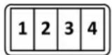
Figure 50: RS232 connector
State indication of the interface:
| Description of indication | ||
| ETH2 – green LED On | Off | Selected 100 MbpsSelected 10 Mbps |
| ETH2 – Yellow LED On | BlinkingOff | The network cable is connectedData transmissionThe network cable is not connected |
| RS485, RS232 – green LED | Indicates Receive data | |
| RS485, RS232 – yellow LED | Indicates Transmit data | |
Table 29: State indication of the RS232-RS485-ETH interface
Technical specification of RS232, RS485 bus and Ethernet IEEE 802.3:
| ETH2, RS485 and RS232 interface | |
| Max. operating RS232 bus current | 15 mA |
| Max. number of devices on RS485 bus | 32 |
| Max. output current on RS485 bus | 60 mA |
| Max. data rate | 230400 bps on RS232230400 bps on RS485100 Mbps on ETH2 |
| Max. total cable length (300 Bd, 200 nF/km) | RS232 20 mRS485 1200 mETH2 100 m |
Table 30: Technical specification of RS232, RS485 and Ethernet
6. First Use
6.1 Connecting the router before first use
Before putting the router into operation it is necessary to connect all of the components that are required to run your applications. Don't forget to insert a SIM card.
!
The router can not operate without a connected antenna, SIM card and power supply. If the antenna is not connected, the router may be damaged.

text_image
SmartFlex RS232 RS485 IN0 IN1 OUT IN0 IN1 OUT RW RW RW RW RW RW RW RW RW RW RW RW RW RW RW RW RW RW RW RW RW RW RW RW RW RW RW RW RW RW RW RW RW RW RW RW RW RW RW RW RW RW RW RW RW RW RW RW RW RW RPM PWR PWR PWR PWR PWR PWR PWR PWR PWR PWR PWR PWR PWR PWR PWR PWR PWR PWR PWR PWR PWR PWR PWR PWR PWR PWR PWR PWR PWR PWR PWR PWR PWR PWRFigure 51: Router connection
6.2 Start
The router will start when a power supply is connected to the router. By default, the router will automatically start to log on to the default APN. The DHCP server will start to assign addresses for devices connected through the Ethernet port ETH0. Router's behavior can be changed via the web interface. This is described in detail in the Configuration manual for SmartFlex routers.
6.3 Configuration

If no SIM card is inserted in the router, it is not possible for the router to operate. Any inserted SIM card must have active data transmission.
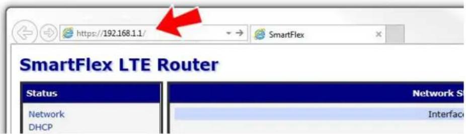
6.3.1 Configuration by web browser
For status monitoring, configuration and administration of the router a web interface is available which can be accessed by entering the IP address of the router into the web browser. The default IP address of the router is 192.168.1.1. Attention, it is necessary to use HTTPS protocol for secure communication over a network!
text_image
https://192.168.1.1/ SmartFlex SmartFlex LTE Router Status Network DHCP Network S InterfaceFigure 52: Entering the IP address of the router
By default, configuration may be performed only by the user "root". The default password is printed on the router's label. ^1 Change the default password as soon as possible!

All routers have the WebAccess/DMP client pre-installed by default. The activated client periodically uploads router identifiers and configuration to the WebAccess/DMP server. See the configuration manual [1], chapter Basic Information -> WebAccess/DMP Configuration, for more information.
After successfully entering login information, the user will have access to the router web interface via their browser.

text_image
Login Username Password LoginFigure 53: Entering login information
| Status | General Status |
| Mobile Connection | |
| General | |
| Mobile WAN | |
| W/R | |
| WiFi Scan | |
| Network | |
| DHCP | |
| IPsec | |
| DynDNS | |
| System Log | |
| Configuration | |
| LAN | |
| VERP | |
| Mobile WAN | |
| PPPE | |
| WiFi | |
| L2TP | |
| FPTP | |
| DynDNS | |
| NTP | |
| SNMP | |
| SMTP | |
| SMS | |
| Expansion Port 1 | |
| Expansion Port 2 | |
| USB Port | |
| Startup Script | |
| Up/Down Script | |
| Automatic Update | |
| Customization | |
| User Modules | |
| Administration | |
| Remote Access | |
| Change Profile | |
| Change Password | |
| Add User | |
| Delete User | |
| Set Real Time Clock | |
| Set SMS Service Center | |
| Unlock SIM Card | |
| Send SMS | |
| Backup Configuration | |
| Restore Configuration | |
| Update Firmware | |
| Reboot | |
Figure 54: Router web interface

A detailed description of the router settings in the Web interface can be found in the Configuration manual for SmartFlex routers.
7. Technical Parameters
7.1 Basic parameters
| SmartFlex Router | ||
| Temperature range Operating | Storage | -40 °C to +75 °C (-40 °F to +167 °F) -40 °C to +85 °C (-40 °F to +185 °F) |
| Cold start -35 | °C | Data transfers via mobile network are available immediately |
| -40 °C | Data transfers via mobile network are avail-able approximately five minutes after the start of the router. Everything else is functional im-mediately. | |
| Humidity Operating | Storage | 0 to 95 % relative humidity non condensing0 to 95 % relative humidity non condensing |
| Altitude Operating 2000 m / 70 kPa | ||
| Degree of protection IP30 | ||
| Supply voltage | 10 to 60 V DC | |
| Battery for RTC | CR1225 | |
| Consumption | Idle | 2.5 W |
| Average | 4 W | |
| Peak | 11 W | |
| Sleep mode | 10 mW | |
| Dimensions | 55 x 97 x 125 mm (2.17" x 3.82" x 4.92") (DIN 35 mm, EN 60715) | |
| Weight | Plastic box | approximately 170 g (0.37 lbs)(depends on interface) |
| Metal box | approximately 380 g (0.83 lbs)(depends on interface) | |
| Antenna connectors | 3x SMA – 50 Ω1x R-SMA – 50 Ω (only for versions with WiFi) | |
| User interface | 2x ETH | Ethernet (10/100 Mbps) |
| USB | USB 2.0 | |
| I/O | 6-pin panel socket | |
| Micro SD | SDHC, SDXC | |
Table 31: Basic parameters
7.2 Standards and Regulations
The router complies with the following standards and regulations.
| Parameter Description | |
| Radio | ETSI EN 301 511, ETSI EN 301 908-1, ETSI EN 301 908-2, ETSI EN 303 413, ETSI EN 301 908-13, ETSI EN 300 328, ETSI EN 301 893 |
| EMC | ETSI EN 301 489-1, ETSI EN 301 489-17, ETSI EN 301 489-19, ETSI EN 301 489-52, EN 55032/24, EN 61000-6-1, EN 61000-6-3 |
| Safety IEC 62368-1 | |
| E-Mark – EMC for devices in transportation | E-Mark homologation number: 10R – 04 9019 |
| National CE, UKCA compliant | |
Table 32: Standards and Regulations
7.3 Type tests and environmental conditions
| Phenomena Test Description Test levels | |||
| ESD EN 61000-4-2 Enclosure contact | Enclosure air | ±6 kV (crit. A) ±8 kV (crit. A) | |
| RF field AM modulated | EN 61000-4-3 Enclosure 20 V/m (crit. A) | (80 - 2700 MHz) 3 V/m (crit. A) (2700 - 6000 MHz) | |
| Fast transient EN 61000-4-4 Signal ports | Power ports Ethernet ports | ±2 kV (crit. A) ±2 kV (crit. A) ±2 kV (crit. A) | |
| Surge EN 61000-4-5 Ethernet ports | Power ports I/O ports | ±2 kV (crit. B), shielded cab. ±0,5 kV (crit. B) ±1 kV, L to L (crit. A) ±2 kV, L to GND (crit. A) | |
| RF conducted | EN 61000-4-6 | All ports | 10 V/m (crit. A) (0,15 - 80 MHz) |
| Radiated emission | EN 55022 | Enclosure | Class B |
| Conducted emission | EN 55022 | DC power ports Ethernet ports | Class B Class B |
| Power frequency magnetic field | EN 61000-4-8 Enclosure 160 A/m (crit. A) | ||
| Dry heat | EN 60068-2-2 +75 | °C*, 40 % rel. humidity | |
| Cold EN 60068-2-1 -40 | °C* | ||
| Damp heat | EN 60068-2-78 | 95 % rel. humidity (+40°C) | |
| Vibration | EN 60068-2-64 ed. 2 | Vibration spectrum A.3 (rolling stock) | Category 1 (3 axis, 8 hours per axis) |
| Shock | EN 60068-2-27 ed. 2 | half-sine, 50 g peak, 11 ms | |
Table 33: Type tests and environmental conditions
* The temperatures given are for the basic version of the router. These can vary for other versions.
7.4 Technical parameters of Cellular Module
| Technical parameters of cellular module | |
| LTE parameters | LTE: Cat.4, 3GPP E-UTRA Release 11FDD frequencies: B20 (800 MHz), B5 (850 MHz), B8 (900 MHz), B3 (1800 MHz), B1 (2100 MHz), B7 (2600 MHz)TDD frequencies: B40 (2300 MHz), B41 (2500 MHz), B38 (2600 MHz)LTE FDD bit rates: 150 Mbps (DL) / 50 Mbps (UL)LTE TDD bit rates: 130 Mbps (DL) / 35 Mbps (UL)Supported bandwidths: 1.4 MHz, 3 MHz, 5 MHz, 10 MHz, 15 MHz, 20 MHzMax power: typical 23 dBm |
| HSPA+ parameters | HSPA: 3GPP R8 DC-HSPA+Supported frequencies: B5 (850 MHz), B8 (900 MHz), B1 (2100 MHz)Bit rates: 42 Mbps (DL) / 5.76 Mbps (UL)Max power: typical 24 dBm |
| UMTS parameters | Supported frequencies: B5 (850 MHz), B8 (900 MHz), B1 (2100 MHz)Bit rates: 384 kbps (DL) / 384 kbps (UL)Max power: typical 24 dBm |
| TD-SCDMA parameters | Supported frequencies: B5 (850 MHz), B8 (900 MHz), B1 (2100 MHz)Bit rates: 4.2 Mbps (DL) / 2.2 Mbps (UL)Max power: typical 24 dBm |
| EDGE parameters | Supported frequencies: 900 MHz, 1800 MHzData throughput: max. 236.8 kbpsMax power: typical 33 dBm |
| GPRS parameters | Supported frequencies: 900 MHz, 1800 MHzData throughput: max. 85.6 kbpsMax power: typical 33 dBm |
Table 34: Technical parameters of cellular module
Antenna Requirements
- VSWR – <2:1 (Antenna input impedance response as function of frequency. This shows the antenna resonances and its bandwidth).
- SMA - 50 Ω
- For good diversity performance, the primary and secondary antennas should have different polarizations.
7.5 Parameters of GNSS
| GNSS specifications | |
| Antenna 50 Ω– active | |
| Protocols NMEA 0183 | |
| GNSS Systems | GPS, GLONASS, BeiDou, Galileo, QZSS |
| Frequency GPS/Galileo/QZSS: | 1575.42 ±1.023 MHz |
| GLONASS: 1597.5 – 1605.8 MHz | |
| BeiDou: 1561.1 ±2.046 MHz | |
| Sensitivity (autonomous) Tracking: | -157 dBm |
| Reacquisition: -157 dBm | |
| Cold start: -146 dBm | |
| Acquisition time (autonomous) | Hot start: 2.5 s |
| Warm start: 26 s | |
| Cold start: 35 s | |
| Accuracy < 1.5 m | |
Table 35: Technical parameters of GNSS
7.6 Technical parameters of WiFi
| WiFi | |
| Antenna connector | R-SMA – 50 Ω |
| Supported WiFi band | 2.4 GHz, 5 Ghz |
| Standards 802.11a, 802.11b, 802.11g, 802.11n | |
| 2.4 GHz supported channels | 1, 2, 3, 4, 5, 6, 7, 8, 9, 10, 11, 12, 13 |
| 5 GHz supported channels^1 | 36, 38, 40, 42, 44, 46, 48, 52, 56, 60, 64, 100, 104, 108, 112, 116, 120, 124, 128, 132, 136, 140, 149, 153, 157, 161, 165 |
| Type of device | Access point, station |
| Max. clients in AP mode | 10 |
| WiFi TX Output Power | 17,3 dBm |
| WiFi RX Sensitivity | -96,3 dBm |
| AP maximum users | 10 users (WiFi module supports multi-role operation in STA and AP. Multi-role does not affect the maximum number of users). |
Table 36: Technical parameters of WiFi
7.7 Technical parameters of I/O port
• Characteristics of inputs:
| Logical 0 / 1* | Voltage Current Web interface status | |
| log. 1 max 3 V 0.4 mA Off | ||
| log. 0 min 5 V 0.7 mA On | ||
| log. 0 type 12 V 2 mA On | ||
| log. 0 max 60 V 7 mA On | ||
Table 37: Characteristics of inputs
* The binary input status in the Shell is returned via io get bin0 or io get bin1.
• Binary output parameters:
- 60 V AC / 300 mA
- 60 V DC / 300 mA
7.8 Technical Parameters of Power over Ethernet (PoE)
Standards IEEE 802.3at-2009 (PoE+) and IEEE 802.3af-2003 (PoE) are supported. Cabling needed is Category 5, up to 12.5 Ω. It is possible to use a passive PoE injector.
| PoE PD: parameters for opposite PSE | |
| Input voltage range | 42.5 – 57 V |
| Power available | 25.50 W |
| Maximum current | 600 mA |
Table 38: PoE PD: parameters for opposite PSE
| PoE PSE parameters | |
| Power supply needed | 44 – 57 V, 65 W |
| Power available | 2x 25.50 W (ETH0, ETH1) |
Table 39: PoE PSE parameters
7.9 Other Technical Parameters
| Parameter Description | |
| CPU power 2 DMIPS per MHz | |
| Flash memory 256 MB | |
| RAM 512 MB | |
| M-RAM 128 kB | |
Table 40: Other technical parameters
8. Related Documents
[1] Advantech Czech: Configuration Manual for SmartFlex Routers

Product-related documents can be obtained on Engineering Portal at http://icr.advantech.cz/address.
9. Troubleshooting
If you cannot connect to the router from your PC, your network card may be configured in such a way that it is not possible to connect to the router. Take one or more of the following steps in order to solve the problem:
- Make sure your PC's network card is configured to obtain the IP address form the DHCP server (by default the DHCP server is running in the router).
- Connect the router to the PC via Switch.
- Connect the router to the PC, start the router first and then start the PC after the router's initialization.
9.1 FAQ

Ethernet connection fails or is not establishing.
- It is possible to turn auto negotiation off and set a rate and duplex manually on the Ethernet interface of the router. Available on "LAN Configuration" page in the router.

Mobile WAN connection fails.
- Check the signal power ("Mobile WAN status" page). If the signal power is weak, you will have to use a better antenna. If the neighbouring cells have a similar signal strength, you will need to use a directional antenna. For proper operation, the signal levels have to be good.
- Try to enable automatic ping from the router, which will check the connection when there are no data running and in the case of a failed ping, restart the connection. This can be done on the "Mobile WAN Configuration" page in the router in the "Check connection" section. "Enable + bind" option is to ensure the ping goes always through Mobile WAN network interface.

Mobile WAN connection cannot be established.
- Check the "Mobile WAN Configuration" – APN, name, password and IP address (all can be blank).
- Try to enter the SIM card PIN – verify that the SIM card has the PIN code entered. Available on "Unlock SIM Card" page in the "Administration" section.
- In a private APN it is not recommended to get the DNS settings from operator (on "Mobile WAN" page)
- Go to "System Log" page in "Status" section and observe where the error occurs.
☐I cannot connect from the Internet to the device behind the router. I have NAT enabled.
- The device's gateway has to be configured so it points to the router.
I can't access my Web server placed behind the router over NAT.
- The remote HTTP access to the router has to be disabled on "NAT Configuration" page in the router. Also enable "Send all remaining incoming packets to default server" feature and fill in the IP address of your Web server. On the Web server, the default gateway has to be the IP address of the router.
DynDNS doesn't work.
- With private APN this will not work.
- If the same IP address is recorded in your canonic name as a dynamically assigned address, it means that the operator is using NAT or a firewall.
- You can verify NAT using ping to your server with static address and then compare with router's IP address.
- You can verify a Firewall by accessing remotely to the router's Web interface.
-
The operator may not provide the address of DNS server and without DNS server's address it is impossible to connect to the dyndns.org server. The following messages will be shown in the System Log:
-
DynDNS daemon started
- Error resolving hostname: no such file or directory
- Connect to DynDNS server failed
L2TP or IPSec isn't establishing.
- Check the "System Log" page for error messages.
IPSec tunnel establishes but the communication does not run.
- Probably there are bad routing rules defined in the connected devices, or the default gateway.
I switched the router to offline mode by SMS message, but the router is in online mode after reboot.
- SMS messages do not change the router configuration. They remain in effect only until the router is rebooted.
Serial communication is not working.
- Verify that the router model supports serial communications. Also verify the serial communication settings. To do so, open the router's configuration menu via the web browser, select the appropriate "Expansion Port" from "Configuration" part of the menu and verify the settings.
Is the router Cisco compatible? Can I use the Cisco configuration?
- No, the Firmware in the router (Conel OS) is based on Linux with BusyBox. Thus the Cisco configuration cannot be used. But network connections are defined by standards so connecting the router to the Cisco or other networking devices is possible and will be compatible.
FTP or SFTP does not work
- FTP will work on v2 routers only. You can use SFTP on all routers to transfer files to/from the router. If having troubles with FTP on v2 routers, make sure you have FTP enabled: "Configuration" section, "Services", "FTP". Then you can connect with any client on port 21 with name and password same as for the Web interface. If having troubles with SFTP, make sure you have SSH enabled: "Configuration" section, "Services", "SSH". Then you can connect with any client on port 22 with name and password same as for the Web interface.
How can I connect to the router's command line? (SSH, Telnet)
- You can use SSH on all routers or Telnet on v2 routers only. SSH is enabled by default, but you can verify in Web interface in "Configuration" section, "Services", "SSH". Then connect with any SSH client on port 22 of the router. User and password is the same as for the Web interface. Telnet on v2 routers can be enabled here: "Configuration" section, "Services", "Telnet".
10. Customer Support
Customer Support for Europe
Advantech Czech s.r.o.
Sokolska 71
562 04, Usti nad Orlici,
Czech Republic
Phone: +353 91 792444
Fax: +353 91 792445
E-mail: iiotcustomerservice@advantech.eu
Web: www.advantech.com
Customer Support for NAM
Advantech B+B SmartWorx
707 Dayton Road
Ottawa, IL 61350 USA
Phone: +1-800-346-3119 (Monday – Friday, 7 a.m. to 5:30 p.m. CST)
Fax: +1-815-433-5109
E-mail: support@advantech-bb.com
Web: www.advantech-bb.com
Customer Support for Asia
Phone: +886-2-2792-7818 #1299 (Monday – Friday, 9 a.m. to 5:30 p.m. UTC+8)
Web: www.advantech.com

We, Advantech Czech s.r.o., declare that the radio equipment narrated in this user's manual complies with Radio Equipment Regulations 2017 (S.I. 2017 No. 1206).

We, Advantech Czech s.r.o., declare that the radio equipment narrated in this user's manual complies with Directive 2014/53/EU.
The full text of the EU Declaration of Conformity is available at the following internet address: icr.advantech.cz/eudoc