
ACPMB-50W - Car Multimedia Interface CRUX - Free user manual and instructions
Find the device manual for free ACPMB-50W CRUX in PDF.

| Product Type | Automotive Multimedia Interface |
| Brand | CRUX |
| Model | ACPMB-50W |
| Compatibility | Mercedes-Benz NTG5 systems (A, B, C, CLA, CLS, GLA, GLC, GLE, GLS, S-Class; 2015-2018) |
| Main Function | Smart-Play Integration: adds wired/wireless Android Auto and Apple CarPlay |
| Camera Support | Front and rear aftermarket camera inputs; retains OEM backup camera |
| Video Connection | 4K HDMI input (from Smart-Play module) and LVDS cable to factory radio |
| Audio Connection | USB to 3.5mm Aux adapter for audio input; factory USB port used |
| Microphone | External 3.5mm microphone for hands-free calls and voice commands |
| Control | Steering wheel controls (long press Back button) to toggle Smart-Play mode; OSD Control Pad for settings |
| Power Supply | 12V DC (tapped from cigarette lighter wires or factory quadlock) |
| DIP Switch Settings | Adjustable per vehicle system and screen size (NTG5.1, 5.2, 5.5) |
| Wireless Connectivity | Wi-Fi and Bluetooth for Android Auto / Apple CarPlay wireless connection |
| Wired Connectivity | USB extension cable for wired Android Auto / CarPlay (optional) |
| Dynamic Parking Guide Lines | Yes, calibration requires turning steering wheel full left/right then center |
| Front Camera Auto-Show | Automatically when shifting from Reverse to Drive; delay adjustable (1-60 seconds) |
| OSD Menu | On-Screen Display accessed via OSD Control Pad for LVDS input, camera settings, save & reboot |
| Parts Included | ACPMB-50W module, main harness, video harness, LVDS cable, USB to Aux adapter, 4K HDMI cable, microphone, OSD controller, 3.5mm Aux cable, optional USB cable, power harness |
| Installation | Professional installation recommended; involves removing radio, tapping into factory wiring, connecting LVDS and quadlock |
| Reparability | Replaceable OSD controller, harnesses, and cables; module is sealed |
Frequently Asked Questions - ACPMB-50W CRUX
User questions about ACPMB-50W CRUX
0 question about this device. Answer the ones you know or ask your own.
Ask a new question about this device
Download the instructions for your Car Multimedia Interface in PDF format for free! Find your manual ACPMB-50W - CRUX and take your electronic device back in hand. On this page are published all the documents necessary for the use of your device. ACPMB-50W by CRUX.
USER MANUAL ACPMB-50W CRUX
- Smart-Play Integration system allows connection of Android and other smartphones to the Mercedes Benz NTG5 infotainment system.
- Integrates wired/ wireless Android Auto and carplay
- Adds front and rear aftermarket camera inputs.
- Retains functionality of the OEM backup camera if present.
- Includes a USB-3.5MM auxiliary audio adapter.
PARTS INCLUDED:


natural_image
Close-up of a black electrical connector with multiple wires and connectors (no visible text or symbols)
ACPMB-50W Module Vehicle Harnesses Smart-Play Interface Module

natural_image
Coiled electronic components including wires, connectors, and a battery pack (no visible text or symbols)Video Harness

LVDS Cable

natural_image
Close-up of a black USB cable with a rectangular connector (no text or symbols visible)USB to Aux Adapter

4K HDMI Cable Microphone

natural_image
Black cordless earphone with attached microphone and clip, no visible text or symbols
OSD Controller

3.5mm Aux Cable

natural_image
Coiled black cable with two connectors, no visible text or symbolsOptional USB Cable (Sold Separately)

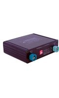
Smart-Play Module Power Harness
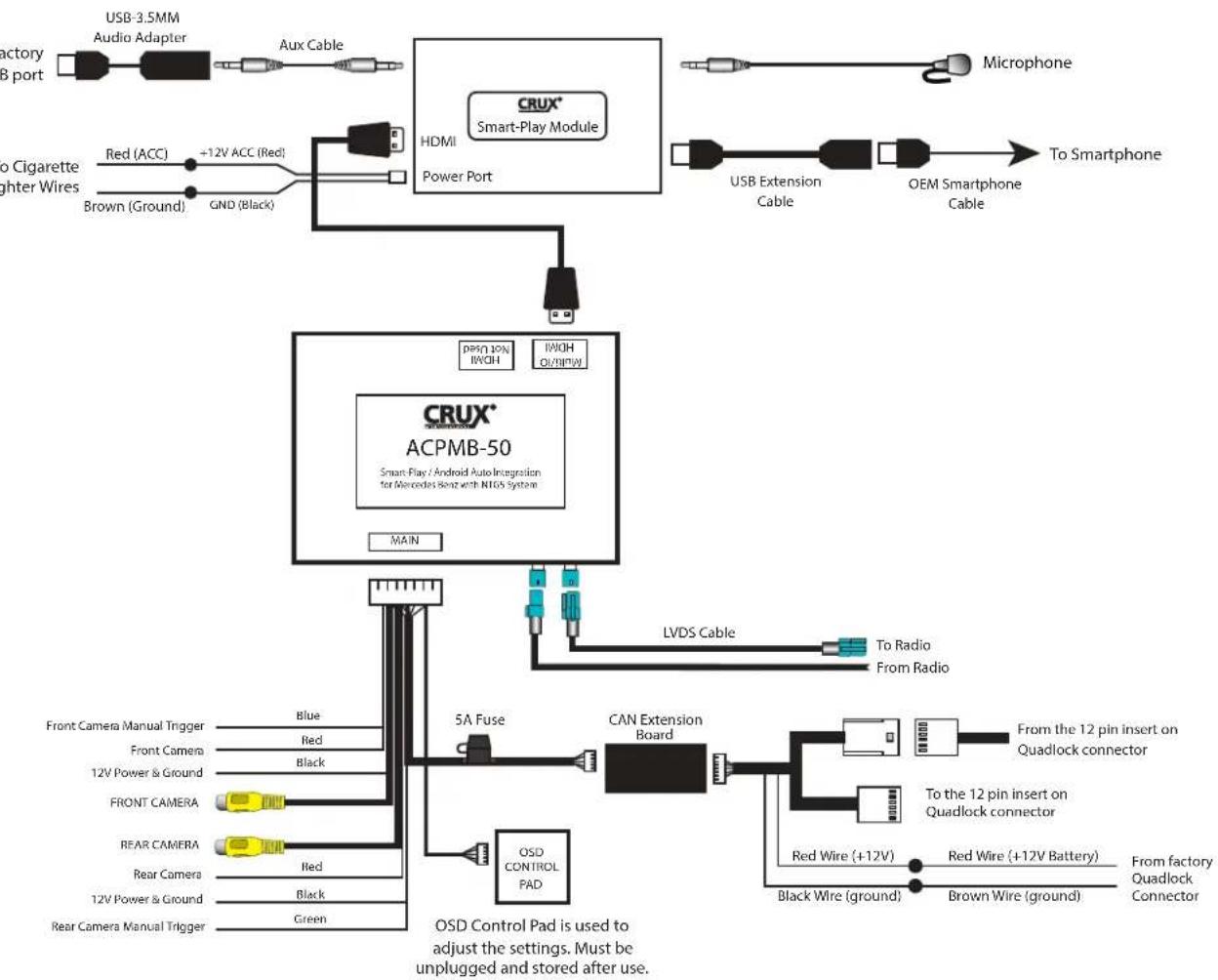
WIRING DIAGRAM:
flowchart
graph TD
    A["Factory USB port"] --> B["USB 3.5MM Audio Adapter"]
    B --> C["Aux Cable"]
    C --> D["HDMI Power Port"]
    D --> E["CRUX® Smart-Play Module"]
    E --> F["Microphone"]
    E --> G["USB Extension Cable"]
    E --> H["OEM Smartphone Cable"]
    I["To Cigarette lighter wires"] --> J["Red (ACC)"]
    J --> K["+12V ACC (Red)"]
    K --> L["Brown (Ground)"]
    K --> M["GND (Black)"]
    N["Main"] --> O["CRUX® ACPMB-50"]
    O --> P["LVDS Cable"]
    P --> Q["To Radio From Radio"]
    R["Front Camera Manual Trigger"] --> S["Blue"]
    T["Front Camera"] --> U["Red"]
    V["12V Power & Ground"] --> W["Black"]
    X["FRONT CAMERA"] --> Y["Red"]
    Z["REAR CAMERA"] --> AA["Black"]
    AB["Rear Camera"] --> AC["Green"]
    AD["12V Power & Ground"] --> AE["Red"]
    AF["Rear Camera Manual Trigger"] --> AG["Green"]
    AH["OSD Control Pad is used to adjust the settings. Must be unplugged and stored after use."] --> AI["5A Fuse"]
    AI --> AJ["CAN Extension Board"]
    AJ --> AK["From the 12 pin insert on Quadlock connector"]
    AJ --> AL["To the 12 pin insert on Quadlock connector"]
    AJ --> AM["Red Wire (+12V)"]
    AJ --> AN["Red Wire (+12V Battery)"]
    AJ --> AO["From factory Quadlock Connector"]
    AJ --> AP["Brown Wire (ground)"]
DIP SWITCH SETTINGS:

Note: ON is down and OFF is up
| DIP SETTING SYSTEM SCREEN SIZE VEHICLE | ||||
| 1 to 8 ALL | OFF NTG5.1 8" A, B | CLA, CLS, GLA, GLE, GLS | ||
| 1 to 8 ALL | OFF NTG5.1 7" A, B | CLA, CLS, GLA, GLE, GLS | ||
| 4 ON NTG5.2 8.4" C, GLC | ||||
| 4 & 7 ON NTG5.2 7" C, V, GLC | ||||
| 3 ON NTG5.5 12.3" S Class | ||||
INSTALLATION INSTRUCTIONS:

natural_image
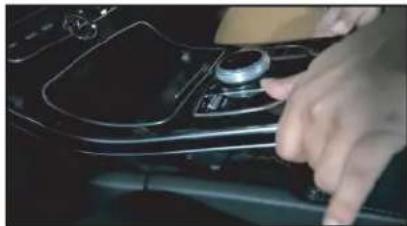
Close-up of hands operating a car gear shift lever on a vehicle (no visible text or symbols)- Remove plastic trim.

natural_image
Close-up of a person's hand inserting a component into a device control panel (no visible text or symbols)- Remove the 2 T20 torx screws. 3.
natural_image
Close-up of a hand pressing down on the dashboard of a car (no visible text or symbols)Carefully pull out up the whole center panel.
natural_image
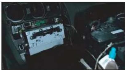
Interior view of a car dashboard with visible electronics and a mounted device (no readable text or symbols)- Remove the 2 screws holding the radio.
natural_image
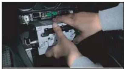
Close-up of hands installing or adjusting a mechanical component with visible wiring and buttons (no text or symbols)- Pull out the radio. 6. Unplug the

natural_image
Close-up of a hand inserting a small electronic component into a car interior (no visible text or symbols)Quadlock connector.
natural_image
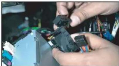
Close-up of hands assembling electronic components with wires and connectors (no visible text or symbols)- Remove the 12-pin connector (black) from the Quadlock connector.

natural_image
Close-up of a hand holding a small electronic component, possibly a battery or connector, with no visible text or symbols.- Remove the insert from the 12-pin connector.

natural_image
Close-up of hands holding a small electronic component with visible wiring and components (no text or symbols)- Install the 12-pin insert from the ACPMB-50W harness to the 12-pin connector.

natural_image
Close-up of hands assembling electronic components with wires and connectors (no visible text or symbols)- Plug the 12-pin connector back to the Quadlock connector.

natural_image
Close-up of hands assembling or adjusting a mechanical component (no visible text or symbols)- Plug in the factory 12-pin insert to the ACPMB-50W harness mate.

natural_image
Close-up of hands installing or adjusting a device on a laptop keyboard (no visible text or symbols)- Plug the Quadlock connector back to the radio.
natural_image
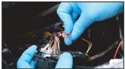
Close-up of hands in blue gloves installing wires on a mechanical component (no visible text or symbols)- Tap the power wires on the ACPMB-50W harness to the Quad-lock connector wires as follows: RED to Red (Battery) Black to Brown (Ground)
natural_image
Close-up of electronic equipment with colored connectors and wiring (no visible text or symbols)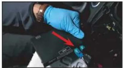
natural_image
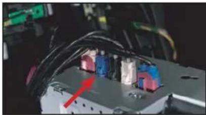
Close-up of a gloved hand holding a black electronic device with a blue connector, no visible text or symbols- Unplug the blue LVDS connector from the radio and plug it to the left side. LVDS port on the module. Note every vehicle might not have the same color LVDS connector.


natural_image
Close-up of a gloved hand inserting a device into a car chassis, with a red arrow pointing to a component (no visible text or symbols)- Plug one end of the LVDS cable provided in the kit to the right side LVDS port on the module.

natural_image
Close-up of mechanical components with blue and red arrows indicating a specific part (no visible text or symbols)- Plug the other end of the LVDS cable to the radio.

natural_image
Close-up of gloved hands working on electronic components with wires and cables (no visible text or symbols)- Install the front and rear cameras (if applicable) and power using the power wires provided.

natural_image
Close-up of gloved hands installing or repairing electronic components with wires (no visible text or symbols)- Tap the Smart-Play module power wires to the cigarette lighter wires as follows: RED to Red (ACC) Black to Brown (Ground)

natural_image
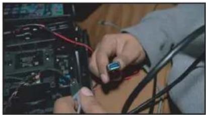
Close-up of a gloved hand holding a small electronic component with a metallic rod (no visible text or symbols)- Plug in the 4K HDMI cable provided with the kit to the Smart-Play module.

natural_image
Close-up of gloved hands holding a black electronic device with red cable and connector (no visible text or symbols)- Plug the 2 pin power wire connector to the Smart-Play module.

natural_image
Back panel of a computer drive showing port, cable, and VGA connectors with red arrows pointing to ports (no text or symbols visible)Line Out (Aux) HDMI Power Port

natural_image
Back panel of a computer drive showing port, cable, and indicator lights (no text or symbols visible)USB Mic In

natural_image
Close-up of gloved hands installing a battery into a car's driver compartment, with a red arrow pointing to the battery (no visible text or symbols)- Plug the other end of the 4K HDMI cable to the ACPMB-50W module HDMI port (left side).

- Plug in the optional USB extension cable to the Smart-Play module for wired AA/ Carplay
natural_image
Close-up of hands working on electronic equipment with cables and components (no visible text or symbols)- Run the other end of the USB extension cable to an accessible location.

- Plug one end of the Aux cable to the Smart-Play module and other end to the USB to Aux adapter.

natural_image
Interior view of a car showing a USB cable and connector (no visible text or symbols)- Plug the USB to Aux adapter to the factory USB port.

natural_image
Close-up of a gloved hand holding a black electronic device with visible wiring and connectors (no readable text or symbols)- Plug in the main power harness to the ACPMB-50W module.

OPERATION:

natural_image
Interior view of a car dashboard with a control panel and directional buttons (no text or symbols visible)To enter and exit the Smart-Play mode, press the back button ↩ on the steering wheel controls for 2 seconds.

1 = Short press for Voice Command
2 = Short press for Return
3 = Rotate and push knob for Smart-Play navigation
ON SCREEN DISPLAY (OSD) SETTINGS:
The OSD Setting Screen automatically pops up when the OSD Control Pad is connected.


Use the OSD menu to make the necessary settings. Remember to Run Save&Reboot after the settings are made. Unplug the OSD Control Pad after setting the cameras and keep it in a secure location in case it is needed to change the settings.
SMART-PLAY SETTING
![[OSD setting] (1/1) Rear Camera ON Front Camera ON LVDS Input ON Input Exten OFF 12V Output Reverse Advance SET > Save&Reboot Run Now Playing Podcasts Audic](/content/2026/06/1228811/images/d8fd3fda94f7f67a60c24e219768b3bcead8e221f448ca7a9b7b024cd7a5afea.jpg)
After plugging in the OSD controller, navigate down to LVDS Input and set to ON. Push RIGHT button to go to the next menu.
![k [LVDS Input] (1/1) Navi Brand NV17 Now Playing Podcasts Audio](/content/2026/06/1228811/images/dd1354b8fc756ce054eaaa8de26bc39403189e0643c768a6dbd8451fd4646811.jpg)
Set Navi Brand to NV17 Nav
![[OSD setting] (1/1) Rear Camera ON Front CameraON LVDS Input ON Input Exten OFF 12V Output Reverse Advance SET > Save&Reboot Run System Ready](/content/2026/06/1228811/images/0c337b4e7564e252800dc8e612f01b0e963bc335959c70cb5a81226c72c7364f.jpg)
igate the OSD back the main menu and go to Save&Reboot then Run.
WIRELESS CARPLAY/WIRELESS ANDROID AUTO CONNECTION SETTINGS
Android Auto Wireless connection
Have Android AutoLink OFF


Have wifi & Bluetooth enabled.

Apple Carplay Wireless Connection

Have wifi & Bluetooth Connected

Wait for screen that will state Use Carplay with "NV17W-WIFI"
SMARTPHONE MIRRORING CONNECTION
Smartphone Mirroring Connection for Iphones

Enable Wi-Fi and connect to "NV17W" module

Open Control Center and Tap Screen Mirroring
a. On iPhone X or later; iPad with iPadOS 13 or later: Swipe down from the upper-right corner of the screen.
b. On iPhone 8 or earlier or IOS 11 or earlier: Swipe up from the bottom edge of screen

Airplay will pull up on screen mirroring app


Select "Airplay"
Smartphone Mirroring Connection for Androids

Enable Android AutoLink

Download Vehicle multimedia entertainment APP Autolink Pro APK

Download AutoLink Pro APP Available in the "Play Store"


On AutoLink Pro APP find the Device and Tap to Connect

Select "Start Now"
REAR AND FRONT CAMERA SETTING
![[OSD setting ] (1/1) Rear Camera ON Front CameraOFF LVDS Input ON Input Exten OFF 12V Output Constant Advance SET > Save&Reboot Run](/content/2026/06/1228811/images/810bfdf6cae8a71639ce5bd824f306020f3cd1733f6976f0654c00d8c9e7df47.jpg)
![[Rear Camera] (1/1) Rear Mode REAR →](/content/2026/06/1228811/images/dcabf35a9fbc29ad8d3069b815efcfd6c6fff7aa82c92cef3bb4a5e555bc2885.jpg)
![< [Rear Mode] (1/1) Rear Input OEM →](/content/2026/06/1228811/images/0a6dac93f6c6a5531316a4dd08a586913530ed4ac2c3abf50b2d6fd65f1dbd18.jpg)

![[OSD setting ] (1/1) Rear Camera ON Front Camera OFF LVDS Input ON Input Exten OFF 12V Output Constant Advance SET > Save&Reboot Run To Save Changes, must press this button at the end.](/content/2026/06/1228811/images/923e3ffb19d27ea4194289c36ebbafba8230dd47509a21f9b70c259469e59944.jpg)

DYNAMIC PARKING GUIDE LINES
![< [Rear Set ] (1/1) Video FormatNTSC FPG (PAS) ON PDC ON Warning LANGON](/content/2026/06/1228811/images/f97cf7131c3c41ce650bb642f65b2892c1f8635bcdd638f05c3299587217cd7e.jpg)
![< [Rear Set ] (1/1) Video FormatNTSC FPG (PAS) ON PDC ON Warning LANGON](/content/2026/06/1228811/images/2d52ac72b0bf9653fa71ee6fc6c7fddb17bd9ea813b5bdce8b2a8a6097557a4c.jpg)
To turn ON the Dynamic Parking Guide Lines, go the Rear Input > Rear Set and turn ON Warning LANG. Go back to the root menu and Run Save&Reboot. Remember to unplug the OSD Control Pad otherwise the unit will not function properly. Set the parking brake on, start the car, put the gear in reverse, turn the steering wheel all the way to the left and all the way to right then put it in the center. The ACPMB-50W will calibrate automatically.

natural_image
Interior view of a vehicle showing a blue triangular ramp and a yellow curved ramp, with no visible text or symbols.FRONT CAMERA SETTINGS
![[OSD setting ] (1/1) Rear Camera ON Front Camera ON LVDS Input ON Input Exten OFF 12V Output Constant Advance SET > Save&Reboot Run](/content/2026/06/1228811/images/f0624e867bd1b70bdf88cbc88abcd43d7c9d881e7da014befad7b8dbc801cb39.jpg)
![< [Front Camera] (1/1) Front Mode FRONT SIDE CAM](/content/2026/06/1228811/images/114c3679844b3c45a1c047c464157f96b980d6a387ff0de27c2a5fc28d4a5db3.jpg)
![< [Front Camera] (1/1) Front Mode FRONT](/content/2026/06/1228811/images/ecaa4934be20cc5a40d80d7c3f4dd6165fe29bf2ec485db44c5aeb030d135d52.jpg)
![< [Front Camera] (1/1) Video FormatNTSC Timer DetectOFF To Turn ON Automatic Front Camera Switching after Reverse Gear to P.N.D.](/content/2026/06/1228811/images/4ce22c2ab0338378aa6a11a3c749863de5f3a4609f813c1377111e7a667a1ff5.jpg)


![[OSD setting] (1/1) Rear Camera ON Front Camera OFF LVDS Input ON Input Exten OFF 12V Output Constant Advance SET > Save&Reboot Run To Save Charges, must press this button at the end.](/content/2026/06/1228811/images/c78308d5ce5c3e0306100833c4551e2c3a00ad150a9f3cbdebeb2d5516fbeed8.jpg)

natural_image
Interior view of a warehouse or factory floor with shelves, tables, and equipment (no visible text or symbols)The front Camera will automatically show on the screen when the gear is put to Drive from Reverse. Set the delay time on the OSD menu. Delay time can be set from 1 to 60 seconds after a putting the car to drive from reverse.
VEHICLE APPLICATIONS:
| Mercedes Benz | |||
| 2015 - 2017 | A-class (W176) | 2017 - Up | GL (X166) |
| 2015 - 2018 | B-class (W24) | 2015 - Up | GLA (X156) |
| 2015 - Up | C-class (W205) | 2015 - Up | GLC (X253) |
| 2015 - 2018 | CLA (C117) | 2015 - Up | GLE (C292) |
| 2015 - 2017 | CLS (W218) | 2015 - 2018 | ML (W166) |
| 2015 - 2016 | E-class (W212) | 2016 - 2018 | SL (R231) |
| 2017 - Up | G (W463) | 2016 - 2018 | SLC (R172) |

Android Auto Screen

CarPlay Screen
TROUBLESHOOTING
*If your call audio does not use car's bluetooth, manually change it on the phone to select the vehicle during the call, then the phone should remember the last used setting


Changing the call audio routing setting to "BLUETOOTH HEADSET"
Go to Settings - Accessibility - Touch - Call Audio Routing. Keep it at "Automatic"
-
IF the screen is black & not showing factory infotainment screen or the CarPlay/Android Auto Screen
-
Confirm secure connection of LVDS cables to the top monitor.
-
Confirm LVDS cables are not damaged, pinched, kinked or bent.
-
No trigger issue /No click heard when long hold applied on BACK button on steering wheel
-
Check and confirm proper connection of the Main Car Interface Harness,
CAN bus board, and 30-pin Car Interface Harness. -
Check and confirm no loose pins or damage to the harness. Green/RED LED Light should be visible from the Metal Box
-
When long hold is applied on BACK button on steering wheel, black screen appears
-
Confirm proper secure connection of the HDMI Cable.
-
Confirm power wire is connected on the CarPlay Box. Red LED light should be visible from the CarPlay Box.
-
Screen image glitching or distorted
- Confirm correct dip switch setting.
-
Hands free call quality noise and echo
-
For iPhone, confirm the phone is connected to your vehicle via Bluetooth and
"Call Audio Routing setting" Keep it at "Automatic" -
For Android, confirm Bluetooth is being used for calls by observing phone's call audio output.
-
No sound
-
Confirm AUX cable connection, which is on the HDMI side of the CarPlay Box.
-
Confirm Car Media Source is in AUX mode. Confirm sound output from the phone to CarPlay module.
-
Siri does not recognize my voice
-
Confirm Microphone jack connection (3.5mm), which is on the USB side of the CarPlay Box.
- Confirm that there are no wire damage.

11 of 11
rev.051222
- PARTS INCLUDED:
- INSTALLATION INSTRUCTIONS:
- OPERATION:
- ON SCREEN DISPLAY (OSD) SETTINGS:
- SMART-PLAY SETTING
- WIRELESS CARPLAY/WIRELESS ANDROID AUTO CONNECTION SETTINGS
- Android Auto Wireless connection
- Apple Carplay Wireless Connection
- SMARTPHONE MIRRORING CONNECTION
- Smartphone Mirroring Connection for Iphones
- Smartphone Mirroring Connection for Androids
- REAR AND FRONT CAMERA SETTING
- DYNAMIC PARKING GUIDE LINES
- FRONT CAMERA SETTINGS
- VEHICLE APPLICATIONS:
- TROUBLESHOOTING
Brand : CRUX
Model : ACPMB-50W
Category : Car Multimedia Interface