
DKGM-16B - Radio Interface CRUX - Free user manual and instructions
Find the device manual for free DKGM-16B CRUX in PDF.

| Product Type | Radio Interface Module |
| Brand | CRUX |
| Model | DKGM-16B |
| Vehicle Compatibility | Select GM LAN 11-bit vehicles (Chevrolet, Pontiac, Saturn models 2004-2012) |
| Retained Features | Factory steering wheel controls, OnStar, chime functions |
| Audio System Support | Non-Bose and Bose amplified systems |
| Navigation Outputs | Reverse, parking brake, illumination, vehicle speed sense |
| Dimensions (approx.) | 3.5 x 2.5 x 1.0 inches (module) |
| Weight (approx.) | 0.5 lb (module and harnesses) |
| Power Input | 12V DC (vehicle battery) |
| Included Parts | Module, 14 & 16-pin harness, 24-pin harness, SWC cables, antenna adapter, dash kit |
| SWC Compatibility | Pre-programmed for most aftermarket radios; dip switch selectable |
| Chime Volume Adjustment | Potentiometer on module (default halfway) |
| Installation Type | Plug-and-play with included harnesses; dash kit for double DIN or single DIN |
| Wiring | EIA color-coded for easy identification |
| Repairability | Not user-serviceable; replace module if defective |
| Safety | Professional installation recommended; disconnect battery before installation |
| Maintenance | No regular maintenance required; keep connections clean and secure |
Frequently Asked Questions - DKGM-16B CRUX
User questions about DKGM-16B CRUX
0 question about this device. Answer the ones you know or ask your own.
Ask a new question about this device
Download the instructions for your Radio Interface in PDF format for free! Find your manual DKGM-16B - CRUX and take your electronic device back in hand. On this page are published all the documents necessary for the use of your device. DKGM-16B by CRUX.
USER MANUAL DKGM-16B CRUX
- Retains factory features in select GM LAN 11 Bit vehicles while functioning with an aftermarket radio.
- Pre-programmed to retain factory Steering Wheel Controls.
- Supports Non-Bose and Bose amplified systems.
- Provides navigational outputs: Reverse Output, Parking brake Output, Illumination, & Vehicle Speed Sense
- Retains factory OnStar ^e
- Retains chime functions.
- EIA color coded wiring for easy installation.
PARTS INCLUDED:
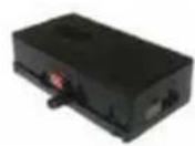
DKGM-16B MODULE
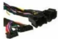
DKGM-16B 14 & 16 PIN HARNESS

DKGM-16B 24 PIN HARNESS

SWC CABLES

ANTENNA ADAPTER

DASH KIT
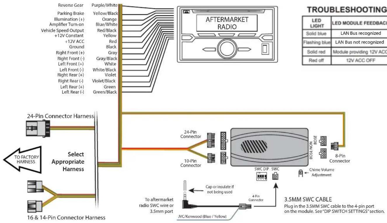
INSTALLATION DIAGRAM:
flowchart
graph TD
    A["24-Pin Connector Harness"] --> B["Select Appropriate Harness"]
    B --> C["16 & 14-Pin Connector Harness"]
    C --> D["To Factory Harness"]
    D --> E["Reverse Gear"]
    E --> F["Purple/White"]
    E --> G["Parking Brake"]
    E --> H["Illumination (+)"]
    E --> I["Amplifier Turn-on"]
    E --> J["Vehicle Speed Output +12V Constant"]
    E --> K["Ground"]
    E --> L["Right Front (-)"]
    E --> M["Left Front (+)"]
    E --> N["Left Front (-)"]
    E --> O["Right Rear (+)"]
    E --> P["Right Rear (-)"]
    E --> Q["Left Rear (+)"]
    E --> R["Left Rear (-)"]

    S["24-Pin Connector"] --> T["10-Pin Connector"]
    T --> U["SWC DIP"]
    T --> V["SWC"]
    U --> W["Chime Volume Adjustment"]
    V --> X["BOSE NON"]
    V --> Y["BOSE"]
    V --> Z["8-Pin Connector"]

    style A fill:#f9f,stroke:#333
    style B fill:#ccf,stroke:#333
    style C fill:#cfc,stroke:#333
    style D fill:#fcc,stroke:#333
    style E fill:#ffc,stroke:#333
    style F fill:#fcc,stroke:#333
    style G fill:#fcc,stroke:#333
    style H fill:#fcc,stroke:#333
    style I fill:#fcc,stroke:#333
    style J fill:#fcc,stroke:#333
    style K fill:#fcc,stroke:#333
    style L fill:#fcc,stroke:#333
    style M fill:#fcc,stroke:#333
    style N fill:#fcc,stroke:#333
    style O fill:#fcc,stroke:#333
    style P fill:#fcc,stroke:#333
    style Q fill:#fcc,stroke:#333
    style R fill:#fcc,stroke:#333
    style S fill:#fcc,stroke:#333
    style T fill:#cff,stroke:#333
    style U fill:#cff,stroke:#333
    style V fill:#cff,stroke:#333
    style W fill:#ffc,stroke:#333
    style X fill:#ffc,stroke:#333
    style Y fill:#ffc,stroke:#333
    style Z fill:#ffc,stroke:#333
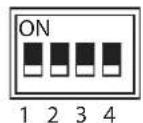
DIP SWITCH SETTINGS:
AFTERMARKET RADIO DIP SWITCH SETTINGS:
| RADIO BRAND: | DIP#: | 1 | 2 | 3 | 4 |
| Atoto, Dual, Fahrenheit, Jensen, Pioneer, Power Acoustik, Soundstream Blaupunkt, Most off-brand Radio Alpine Clarion Kenwood JVC Boss, Old Sony New Sony | OFF | OFF | ON | ON | |
| OFF | OFF | ON | ON | ||
| OFF | OFF | ON | ON | ||
| OFF | OFF | OFF | OFF | ||
| OFF | ON | ON | OFF | ||
| OFF | ON | ON | ON | ||
| OFF | ON | OFF | ON | ||
| OFF | ON | OFF | OFF | ||
| OFF | OFF | ON | OFF |
SWC MODULE
DIP SWITCH
NOTE: For Atoto, Blaupunkt, Dual, Farenheit, Power Acoustik, Soundstream, and most off-brand radios, check the aftermarket radio's manual to see if the SWC buttons need to be programmed.
4-PIN SWC CABLE
Use the proper 3.5MM to 4-Pin SWC cable for the aftermarket radio you are using.
OPTION A is used for ALPINE, CLARION, JVC, and KENWOOD units (Blue/Yellow wire is attached) OPTION B is used for BLAUPUNKT, BOSS, DUAL, FARENHEIT, JENSEN, POWER ACOUSTIK, PIONEER, SONY, SOUNDSTREAM and Most Off-Brand Radios.
NOTE: Cap or insulate the 3.5mm plug or Blue/Yellow wire if not being used.
Plug the SWC cable to the SOOGM-16B module and the 3.5mm plug to the aftermarket radio SWC port or use the Blue/Yellow wire for JVC and Kenwood radios.
SELECTING THE AUDIO SYSTEM:
If the vehicle is equipped with an amplified audio system, the DKGM-16B has a built-in audio level adaptor that outputs the proper audio level from the aftermarket radio to the factory amplifier. To use this feature, plug in the male 8-pin connector on the DKGM-16B harness to the GRAY female 8-pin connector on the DKGM-16B module. The module is also labeled "Bose" and "Non Bose" to avoid confusion. (see picture below)
If the vehicle is NOT equipped with a factory amplified system, plug in the male 8-pin connector to the BLACK female 8-pin on the DKGM-16B module.
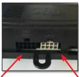
natural_image
Close-up of a computer monitor rear panel showing an attached port with two connectors and red arrows pointing to the ports (no text or symbols visible)NON BOSE
(Non-Amplified)
Connection
BOSE
(Amplified)
Connection
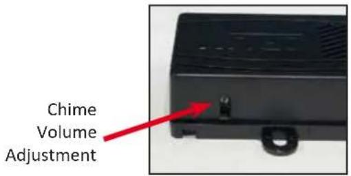
CHIME VOLUME ADJUSTMENT:
The DKGM-16B has a potentiometer to adjust the chime volume. It is set at half way by default. To adjust the volume, simply use a suitable screw driver and turn the potentiometer clockwise to increase the volume and counter-clockwise to decrease the volume.
ONSTAR VOLUME ADJUSTMENT:
To adjust the OnStar volume, turn on OnStar and adjust the volume using the Steering Wheel Control volume adjustment. Once it is set, the DKGM-16B will memorize this level.
DASH KIT INSTALLATION:
A double DIN radio replacement dash kit is included in the kit to make the installation quick and easy. You have the option of installing a Double DIN or two Single DIN radios. The DKGM-16B kit includes:
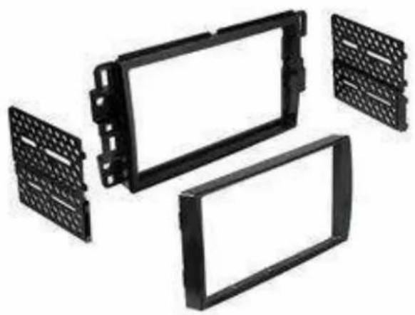
natural_image
Exploded view of a black plastic enclosure with grid patterns, shown from three different angles (no text or symbols visible)INSTALLATION:
Before installation:
- Locate the main trim ring.
- Locate the left and right mounting brackets.
- Slide the appropriate mounting bracket into the trim ring, aligning the holes in the trim ring to the clips on the bracket. (See Diagram A on page 4)
- For two Single DIN radio installation, slide the stacked ISO DIN unit into the trim ring bracket assembly and secure the unit to the kit using the screws supplied with the radio. (See Diagram B on page 4)
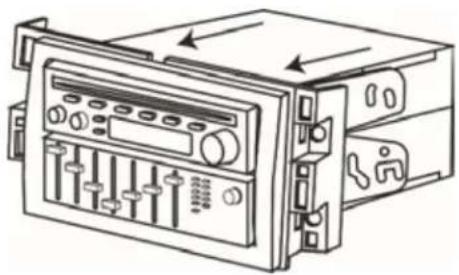
INSTALLATION (Continued):
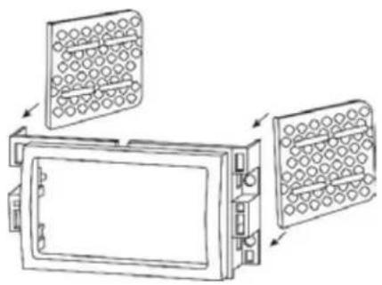
natural_image
Diagram of a device with two panels, showing internal components and directional arrows (no text or symbols)Diagram A
natural_image
Line drawing of a mechanical device with control panel and buttons (no text or symbols)Diagram B
VEHICLE APPLICATIONS:
16 and 14 PIN CONNECTORS
CHEVROLET
| 2007-2010 | Cobalt |
| 2006-2011 | HHR |
| 2008-2012 | Malibu |
PONTIAC
| 2007-2009 | G5 |
| 2010 | G6 |
| 2006-2009 | Solstice |
SATURN
| 2007-2009 | Aura |
| 2007 | Ion |
| 2007-2010 | Sky |
24 PIN CONNECTOR
CHEVROLET
| 2005-2006 | Cobalt |
| 2004-2007 | Malibu |
| PONTIAC | |
| 2005-2009 | G6 |
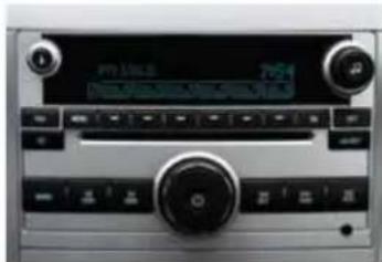
Compatible Radios

natural_image
Interior view of a car dashboard with control knobs and a central rotary knob (no visible text or symbols)2009 Pontiac G6 2009 Chevrolet Malibu
natural_image
Close-up of a car air conditioning control panel with no visible text or symbols on the device surface.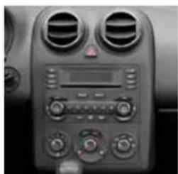
natural_image
Interior view of a car dashboard with air conditioners and gauges (no visible text or symbols)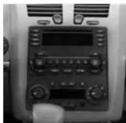
natural_image
Interior view of a car dashboard with analog controls and ventilation grilles (no visible text or labels)2006 Pontiac G6 2005 Chevrolet Malibu

Brand : CRUX
Model : DKGM-16B
Category : Radio Interface