PA 7200 - Measurement PCE Instruments - Free user manual and instructions
Find the device manual for free PA 7200 PCE Instruments in PDF.

User questions about PA 7200 PCE Instruments
0 question about this device. Answer the ones you know or ask your own.
Ask a new question about this device
Download the instructions for your Measurement in PDF format for free! Find your manual PA 7200 - PCE Instruments and take your electronic device back in hand. On this page are published all the documents necessary for the use of your device. PA 7200 by PCE Instruments.
USER MANUAL PA 7200 PCE Instruments
natural_image
Abstract logo design with blue and yellow curved shapes forming a circular motif (no text or symbols)PCE INSTRUMENTS
POWER ANALYZER
PCE-PA 7200

text_image
50.70" 2000.2535.INSTRUCTION MANUAL
1. INTRODUCTION
NOTE
This Power Meter has been designed and tested according to CE Safety Requirements for Electronic Measuring Apparatus, IEC/EN 61010-1 and other safety standards. Follow all warnings to ensure safe operation.
WARNING
READ "SAFETY NOTES" (NEXT PAGE) BEFORE USING THE METER.
CAT IV – Measurements performed at the source of the low voltage installation.
CAT III – Measurements performed in the building installation.
CAT II – Measurements performed on circuits directly connected to the low voltage installation.
2. SAFETY NOTES
- Read the following safety information carefully before attempting to operate or service the meter.
- Use the meter only as specified in this manual.
Otherwise the protection provided by the meter may be impaired. - Keep drying when using this product.
- To reduce the risk of electric shock, do not remove cover.
- Do not use this product while is getting wet.
- Never give shocks, such as vibration or drop, which may damage the meter.
- The maximum measurement current is 1000A.
-
Rated environmental conditions :
(1) Indoor 600Vac.
(2) Installation Category III.
(3) Pollution Degree 2.
(4) Altitude up to 2000 meter.
(5) Relative humidity 80% max.
(6) Ambient temperature 0\~40°C. -
Observe the International Electrical Symbols listed below :

Detector is protected throughout by double insulation or reinforced insulation.

Warning ! Risk of electric shock .

Caution ! Refer to this manual before using the product.

AC; Alternating Current
3. FEATURES
- Determine the running cost of your appliances.
- Measure voltage, current, frequency, watt, power factor, and greenhouse gas emissions.
- Log and Recall function.
- Enable users to read the data in memory directly on the meter without connecting to a PC.
- Optical USB to RS-232 data transmission.
- 2 Optical LEDs are built-in for data transfer.
- Transferring and showing real-time data to a PC.
- Make informed decisions when purchasing appliances and equipment.
- Reduce your electricity bill.
- Calculate electrical expenses by real, hour.
- Data communication function.
- Freely set upper and lower limit for V, A, W and alarm when measured value is out of limit.
-
Backlight function.
-
SPECIFICATIONS
| Item | Range | Resolution | Accuracy |
| AC voltage | 600 V | 0.1V | ±1%±5dgt |
| AC current | 1000 A | 0.1A | ±1.5%±5dgt (>10A) |
| Power | 0-9999 kW | ±2.5%±5dgt | |
| Apparent power | 0-9999 kVA | ±2.5%±5dgt | |
| Power factor | 0.001-1 | 0.001 | |
| Frequency | 45-65 Hz | 0.1 | ±0.5%±5dgt |
| Cost | 9999 $ | ||
| Energy | 9999 kWh | ||
| Gas | 9999 kg | ||
| Cost setting | 0-9999 kWh | ||
| Gassetting | 0-9999 kg / kWh |
- Dimensions :
Power Meter: 177(L) × 200(W) × 105(D)mm
AC Current Clamp: 212(L) × 100(W) × 47(D)mm
- Weight : Approx. 1400g
- Safety standards: IEC / EN 61010-1 CAT III 600V
EN 61326-1
• Power source: 1.5V(AA) × 6
5. INSTRUMENT LAYOUT

text_image
(1) (2) (3) (4) (5) (8)(11) (12) (13) (7) (9) (10)(6) SELECT RESET BACKLIGHT POWER MODE SET MINSTOP LOG RECALL HOLD POWER METER CAT IN 600V (14) (15)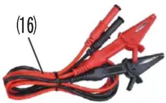
natural_image
Coiled red and black electrical test probes with label (16) pointing to the cable (no text or symbols on the devices themselves)(1) AC Current Clamp: Output voltage 0.5mV/1A.
(2) ACV Terminal: Input AC voltage.
(3) ACA Terminal: Input AC current.
(4) LCD Display Screen: LED display.
(5) Select Button:
Display kW/kVA/ACV/ACA maximum and minimum
Display kWh/CO2/cost real and hour duration data
(6) Reset Button: Reset all test data.
(7) Backlight Button: ON or OFF backlight function.
(8) Mode Button: Select kW, PF, kVA, HZ, ACV, ACA, kWh, CO2, cost and time mode.
(9) Set Button:
ACV/ACA/kW upper/lower alarm and CO2/cost rate set and test time function setting.
(10) Run/Stop Button: Start or pause process during the measurement period
(11) Log Button: The data is stored 2000 records.
(12) Recall Button:
Stored records data can be re-called from the memory.
(13) Hold Button: Data hold.
(14) Terminal for PC Interface: connect data transmission cable.
(15) Power Button: Power on/off.
(16) Test leads.
6. MEASURING METHODS
The meter is a multiple measurement function of AC power meter.
Those functions are voltage, current, watt, va, frequency, power factor, power consumption and actual cost of power consumed measurement.
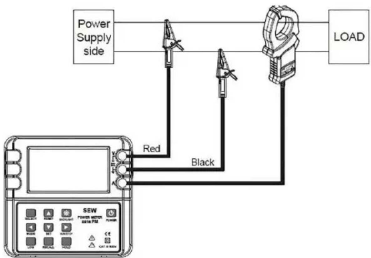
Connections:
- AC Voltage Measurement:
Insert the Red test lead to the Red testing terminal and insert the Black test lead to the Black testing terminal.
- AC Current Measurement:
Insert the Clamp sensor test lead to the BNC terminal
flowchart
graph TD
    A["Power Supply side"] --> B["Load"]
    C["SEW device"] --> D["Red"]
    C --> E["Black"]
    C --> F["Black"]
Power Measurement on Single-Phase Two-Wire Circuit
6-1. Main buttons functions of power meter
MODE Button :
You can select different modes by pressing MODE button.
These modes are watts, power factor, apparent power, frequency, AC voltage, AC current, kWh, GAS, cost and time mode.
SELECT Button :
When the main modes are watts, apparent power, AC voltage, AC current modes, press the SELECT button can see the detail of maximum and minimum on the display.
Other main mode like kWh, GAS, COST mode when pressing the SELECT button, you can see the detail of REAL, HOUR, duration on the display.
Under the time mode, press the SELECT button can select different display of time mode, (min/sec) mode, (hours)mode, (days/hours)mode.
SET Button :
- Alarm function:
Under the watt, AC voltage and AC current modes press the SET button can set UPPER and LOWER limit alarm functions.
- Time setting function:
Under the time setting mode, press the SET button can set run-time or end-time test duration.
RESET Button :
Press and hold the RESET button can reset all test data.
RUN/STOP Button :
Press the RUN/STOP button can start or pause process during the measurement period.
BACKLIGHT Button :
Press the BACKLIGHT button, the LCD will have backlight function.
LOG Button :
Press LOG button, the display will show "LOG" on the power meter, and the data is stored 2000 records. The data is stored every second until the memory full. Press the RUN/STOP button to execution.
RE-CALL Button :
Press the "RECALL" button into the RE-CALL mode. the data in the memory can be re-called on the LCD.
Hold Button:
Data hold.
Power Button:
Power on/off.
6-2. Screen mode
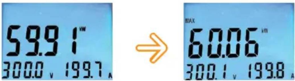
6-2-1. WATTS Screen Mode:
- Press the SELECT button can show the detail of MAX/MIN on the display.
text_image
59.91 300.0 v 199.7 A → MAX 60.06 300.1 v 199.8 A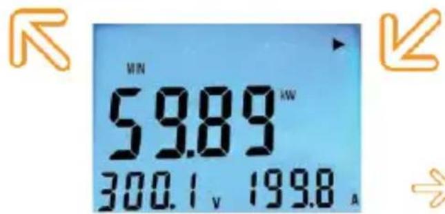
text_image
MIN 59.89 kW 300.1 v 199.8 A
: Press the SELECT button can see MAX/MIN watts.
- SET Alarm
Press the SET button can set watt alarm to the upper/lower limit mode.
Press the SELECT button can change the upper or lower limit.
Press the MODE (◀) button can change flashing number position.
Press the RESET(▲) button to increase the flashing digit (0→9).
Press the SET(▼) button to decrease the flashing digit (9→0).
Press the RUN/STOP(▶) button to confirm the setting number.

text_image
UPPER SET ALARM 600.0 kW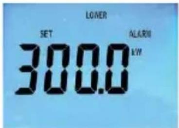
text_image
LOWER SET 300.0 ALARM kW
text_image
UPPER SET OFF ALARM kW6-2-2. POWER FACTOR Screen Mode :
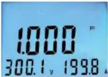
text_image
1.000 300.1 v 19986-2-3. Apparent Power Screen Mode :
- Press the SELECT button can show the detail of MAX/MIN on the display.

text_image
59.95 kVA 300.1 v 199.8 A → MAX 59.95 kVA 300.0 v 199.7 A

text_image
59.89 300.0 v 199.8 A

: Press the SELECT button can see MAX/MIN apparent power.
6-2-4. Frequency Screen Mode :
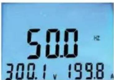
text_image
50.0 Hz 300.1, 199.8,6-2-5. AC Voltage Screen Mode :
- Press the SELECT button can show the detail of MAX/MIN on the display.
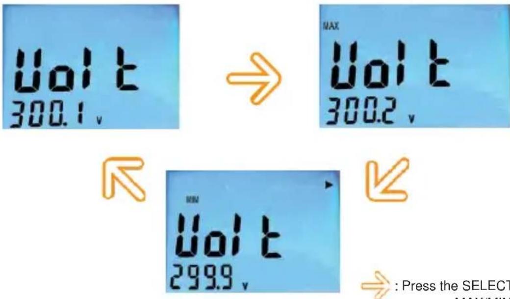
text_image
Vol t 300.1 v → MAX Vol t 300.2 v ← Vol t 299.9 v ← → : Press the SELECT MAX/MIN
: Press the SELECT button can see MAX/MIN AC Voltage.
- SET Alarm
Press the SET button can set AC voltage alarm to the upper/lower limit mode.
Press the SELECT button can change the upper or lower limit.
Press the MODE(◀) button can change flashing number position.
Press the RESET(▲) button to increase the flashing digit (0→9).
Press the SET(▼) button to decrease the flashing digit (9→0).
Press the RUN/STOP(▶) button to confirm the setting number.

text_image
UPPER SET ALARM II 300U
text_image
LOWER SET ALARM 1000
text_image
UPPER SET OFF ALARM6-2-6. AC Current Screen Mode :
- Press the SELECT button can show the detail of MAX/MIN on the display.
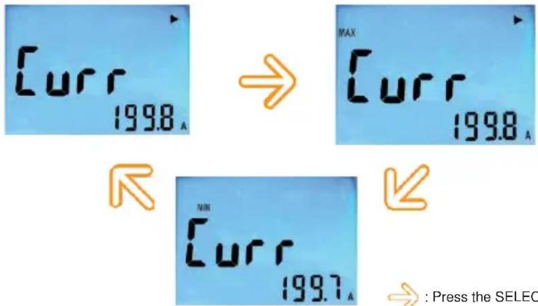
text_image
Curr 1998_A → MAX Curr 1998_A ← Curr 1997_A ← → : Press the SELEC
: Press the SELECT button can see MAX/MIN AC Current.
- SET Alarm
Press the SET button can set AC current alarm to the upper/lower limit mode.
Press the SELECT button can change the upper or lower limit.
Press the MODE(◀) button can change flashing number position.
Press the RESET(▲) button to increase the flashing digit (0→9).
Press the SET(▼) button to decrease the flashing digit (9→0).
Press the RUN/STOP(▶) button to confirm the setting number.
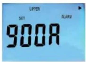
text_image
UPPER SET 900R ALARM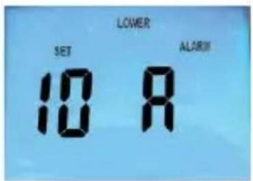
text_image
LOWER SET ALARM 10 R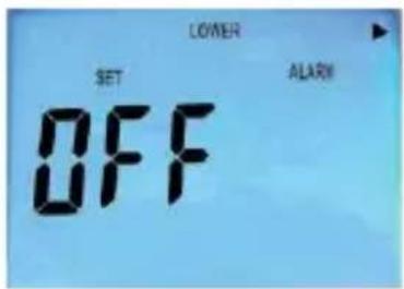
text_image
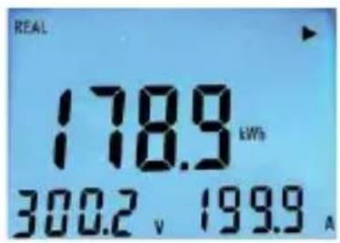
LOWER SET ALARM OFF6-2-7. kWh Screen Mode :
- SELECT REAL/HOUR function
text_image
REAL 178.9 kWh 300.2 v 199.9 A
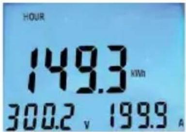
text_image
HOUR 149.3 kWh 300.2 V 199.9 A
: Press the SELECT button can see REAL/HOUR kWh.
Press the SET button can set GAS rating.
Press the MODE(◀) button can flashing number position.
Press the RESET(▲) button to increase the flashing digit (0→9).
Press the SET(▼) button to decrease the flashing digit (9→0).
Press the RUN/STOP(▶) button to confirm the setting number.

text_image
SET RATE 3.000 kWh kg6-2-9. COST Screen Mode :
- SELECT REAL/HOUR function
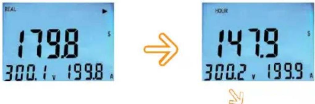
text_image
REAL 179.8 $ 300.1, 199.8 A → HOUR 147.9 $ 300.2, 199.9 A: Press the SELECT button can see REAL/HOUR cost.
- SELECT COST RATE
Press the SET button can set COST rating.
Press the MODE(◀) button can flashing number position.
Press the RESET(▲) button to increase the flashing digit (0→9).
Press the SET(▼) button to decrease the flashing digit (9→0).
Press the RUN/STOP(▶) button to confirm the setting number.

text_image
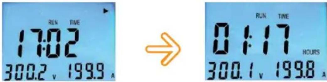
SET RATE 6.000 L/kW6-2-10. TIME Screen Mode :
- SELECT TIME MODE
text_image
RUN TIME 17:02 300.2 v 199.9 A → RUN TIME 01:17 HOURS 300.1 v 199.8 A
text_image
RUN TIME 00.01 DAYS HOURS 300.0 V 199.8 A → : P: Press the SELECT button can see minutes and seconds/HOURS/DAYS HOURS time mode.
- SET TIME MODE
Press the SET button can set TIME duration.
Press the MODE(◀) button can flashing number position.
Press the RESET(▲) button to increase the flashing digits.
Press the SET(▼) button to decrease the flashing digits.
Press the RUN/STOP(▶) button to confirm the setting number.

text_image
00:50 RUN TIME II 0.0 v 0.0 A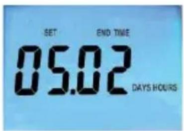
text_image
SET END TIME 05.02 DAYS HOURS6-2-11. LOG Screen Mode:
- SELECT LOG MODE
Connect teh data transfer cable to the power meter and PC all the records can be saved in the memory and recalled to a PC and downloading saved data a PC. Press LOG button ,the display will show "LOG" on the power meter, and the data is stored 2000 records. The data is stored every second until the memory full.
Press the RUN/STOP(▶) button to execution.
Reset memory data can Press the "RESET" button clear all memory data.

text_image
Log 300.1, 1998

text_image
FULL 300.2, 199.9,- RE-CALL Mode:
Press the "RECALL" button into the RE-CALL mode the data in the memory can be re-called on the LCD.
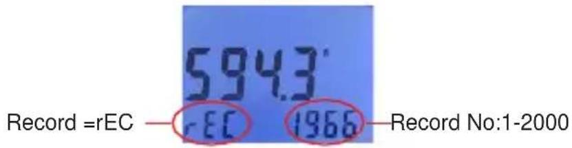
text_image
594.3° Record =rEC — rEC 1966 — Record No:1-2000Press the "MODE" button to read different parameters, such as watts, power factor, apparent power, frequency, AC voltage, AC current, kWh, GAS, cost.
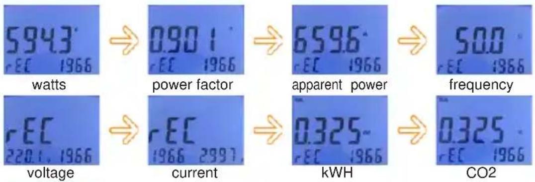
text_image
5943 rEC 1966 watts → 0.901 rEC 1966 power factor → 6596 rEC 1966 apparent power → 500 rEC 1966 frequency rEC 220.1, 1966 voltage → rEC 1966 2997, current → 0.325- rEC 1966 kWH → 0.325 rEC 1966 CO2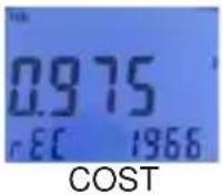
Press the RESET (▲) button or the SET(▼) button to select the record. If press the RESET button or SET button for more than 1S, the number of the record will be added by 10 or deducted by 10.


Pressing the "RESET" button can clear all the data in the memory. Press the "SELECT" button for more than 3 seconds to escape from LOG mode or RE-CALL mode, and will get into the normal mode.
normal mode
6-2-12. Other:
- LCD Back-light
Press the "backlight" button to enable the back light function. You can press the "backlight" button again to disable the function.
7. CLEANING & STORAGE
Periodically wipe the case with a damp cloth and detergent. Do not use abrasives or solvents.
8. PC COMMUNICATION METHOD
(a) Power meter is compatible with RS232 communication.
(b) The basic transmission protocol is as follows: Transmission protocols can be confirmed from a hyper terminal.
(1) Communication port : connect to a created port in the case of a serial communication port.
(2) Transmission speed : 9600
(3) Parity : none
(4) Stop bit :1
(5) Flow control : none
(6) Normal mode :
When the english capital letter "C" is transmitted from a PC is pressed, data will be consecutively received and "COMM" will be displayed on the product's screen. When the english capital letter "P" is transmitted, the communication will be cancelled.
N-1108V 00000A 00000W 00000VA PF0000 0599Hz 0000000WH N-1108V 00000A 00000W 00000VA PF0000 0599Hz 0000000WH N-1108V 00000A 00000W 00000VA PF0000 0599Hz 0000000WH :
(7) Log mode :
When the english capital letter "L" is transmitted from a PC is pressed, data will be consecutively received and "COMM" will be displayed on the product's screen. When the english capital letter "P" is transmitted, the communication will be cancelled.
L0000-1126V 00000A 00000W 00000VA PF0000 0600Hz 0000000V L0001-1126V 00000A 00000W 00000VA PF0000 0600Hz 0000000V L0002-1126V 00000A 00000W 00000VA PF0000 0600Hz 0000000V L0003-1126V 00000A 00000W 00000VA PF0000 0600Hz 0000000V :
9. INTERFACE CONNECTION AND OPERATION
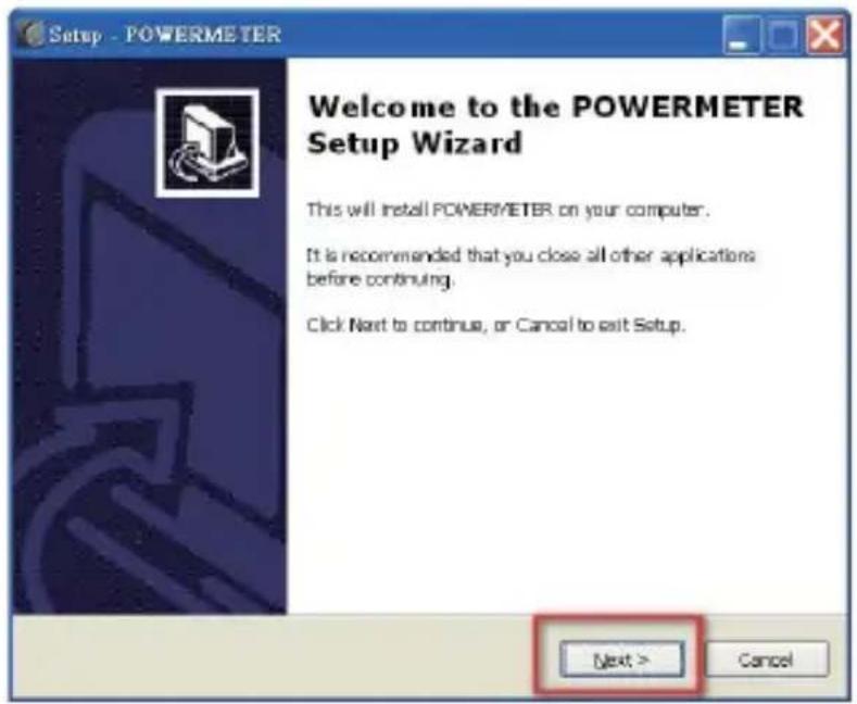
(a)This power meter program will set up on your computer automatically.
text_image
Setup - POWERMETER Welcome to the POWERMETER Setup Wizard This will install POWERMETER on your computer. It is recommended that you close all other applications before continuing. Click Next to continue, or Cancel to exit Setup. Next > Cancel(b) If you want to install a different folder, click Browse, and select another folder.
If it's not necessary, click the "Next" button.
text_image
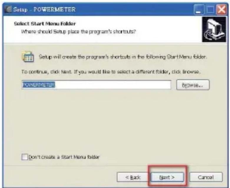
Setup - POWERMETER Select Start Menu Folder Where should Setup place the program's shortcuts? Setup will create the program's shortcuts in the following StartMenu folder. To continue, click Next. If you would like to select a different folder, click Browse. POWERMETER Browse... Don't create a Start Menu folder < Back Next > Cancel(c) Click the "Next" button.
text_image
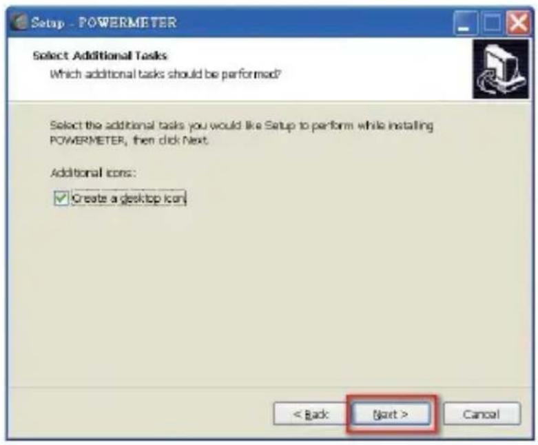
Setup - POWERMETER Select Additional Tasks Which additional tasks should be performed? Select the additional tasks you would like Setup to perform while installing POWERMETER, then click Next. Additional icons: ✓ Create a desktop icon < Back Next > Canceltext_image
Setup - POWERMETER Ready to Install Setup is now ready to begin installing POWERMETER on your computer. Click: Install to continue with the installation, or click Back if you want to review or change any settings. Destination location: C:\Program Files\POWERMETER Start Menu folder: POWERMETER additional tasks: Additional icons: Create a desktop icon < Back Install Cancel(e) It will show the information of power meter has been successfully installed, then click "Finish" button.
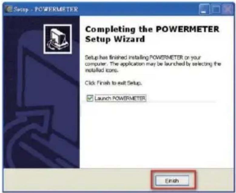
text_image
Setup - POWERMETER Completing the POWERMETER Setup Wizard Setup has finished installing POWERMETER on your computer. The application may be launched by selecting the installed icons. Click Finish to exit Setup. Launch POWERMETER Finish※Install the driver on your personal computer. It's very important to install the driver on your computer. Your computer can not communicate with the Power meter without installing the driver. The driver is also on the USB pen drive. The directory is "E:/USB DRIVER".
10. RS232 PROGRAM
10-1. Initial screen and setting
Click on the POWER METER icon, then a program will be run.

10-2. Data collection and data analysis
10-2-1. Data collection on monitor mode
Click on "set up" and enter the appropriate communication and default settings.

text_image
POWER METER Data Table Voltage Current Active Power / Wall/Heavy Power Source Transparency OCP - Vcc Start Local Report AC/POWER/DC/DC/DC/DC/DC/DC/DC/DC/DC/DC/DC/DC/DC/DC/DC/DC/DC/DC/DC/DC/DC/DC/DC/DC/DC/DC/DC/DC/DC/DC/DC/DC/DC/DC/DC/DC/DC/DC/DC/DC/DC/DC/DC/DC/DC/DC/DC/DC/DC/DC/NC No Time Voltage Current Active Apparent Reactive Power Power Factor Frequency Wall CDS Out [V] [A] [W] [VA] [VA] [PF] [PE] [WH] [Ko] [$] Min Max Average Average There are no done to show in this view. Monitor History Log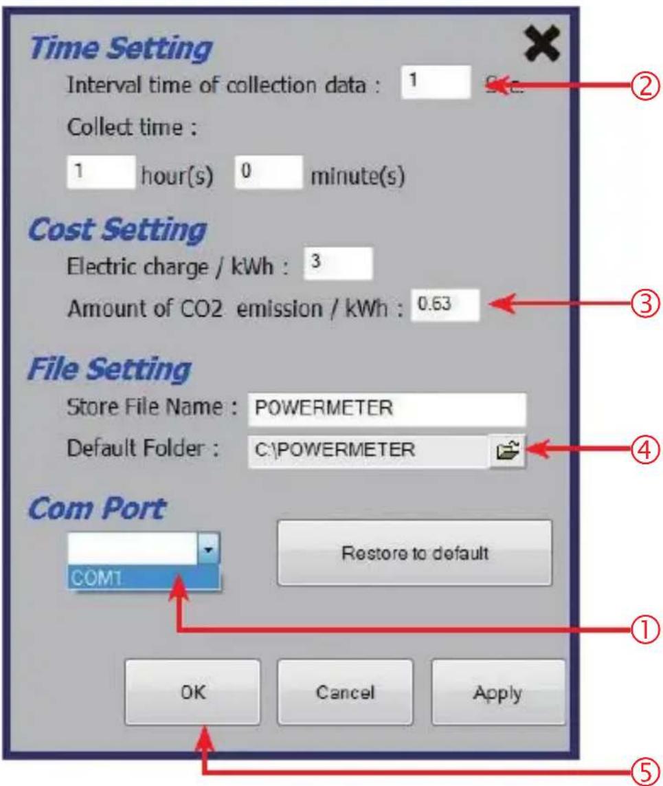
text_image
Time Setting Interval time of collection data : 1 Collect time : 1 hour(s) 0 minute(s) Cost Setting Electric charge / kWh : 3 Amount of CO2 emission / kWh : 0.63 File Setting Store File Name : POWERMETER Default Folder : C:\POWERMETER Com Port COM1 Restore to default OK Cancel Apply ① ② ③ ④ ⑤① Click on the "Com Port" and select the RS 232 port number.(select a created port number.)
② Select an appropriate interval for data collection. (Range : 1\~60sec.) and Set the time for data collection. The maximum is 24 hour.
③ Set an electric charge per 1 kWh, and a CO2 emission.
④ File Setting.
⑤ When all setting has done, Press "OK" button.
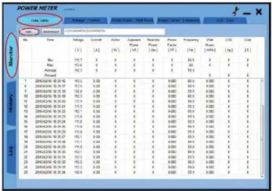
Select the "Monitor" and "Data Table" and press the "Start" button. If RS 232 link has succeeded with POWER METER, then the LCD will show "COMM".
text_image
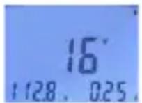
POWER METER Date Table Voltage Control Active Power Wall Load Power Level Frequency CO2 Grid SN1 Standard Circulation/Powerchart No Time Voltage Current Action Apparent Reporting Power Frequency Vial CO2 Cost [V] [A] [W] Power Factor [F] [Hz] Hours [kWh] [kg] [S] Max 115.7 9 0 0 0 0 4 50.0 8 8 8 Max 113.4 9 0 0 0 0 40 6 8 8 Average 112.3 9 0 0 0 0 59.9 Amount 7 2015/02/16 10:25:19 113.5 0.00 0 0 0 9.000 60.0 9.000 8 8 8 2015/02/16 10:25:17 113.6 0.00 0 0 0 9.000 59.9 9.000 8 8 9 2015/02/16 10:25:19 112.6 0.00 0 0 0 9.000 55.5 9.000 8 8 10 2015/02/16 10:26:19 112.3 0.00 0 0 0 9.000 60.6 9.000 8 8 11 2015/02/16 10:26:20 111.9 0.00 0 0 0 9.000 59.8 9.000 8 8 12 2015/02/16 10:26:21 111.5 0.00 0 0 0 9.000 53.6 9.000 8 8 13 2015/02/16 10:26:22 112.1 0.00 0 0 0 9.000 59.9 9.000 8 8 14 2015/02/16 10:26:23 111.8 0.00 0 0 0 9.000 55.5 9.000 8 8 15 2015/02/16 10:26:24 111.9 0.03 0 0 0 9.000 53.6 9.000 8 8 16 2015/02/16 10:26:25 111.8 0.3310-2-2. Data Collection on History mode
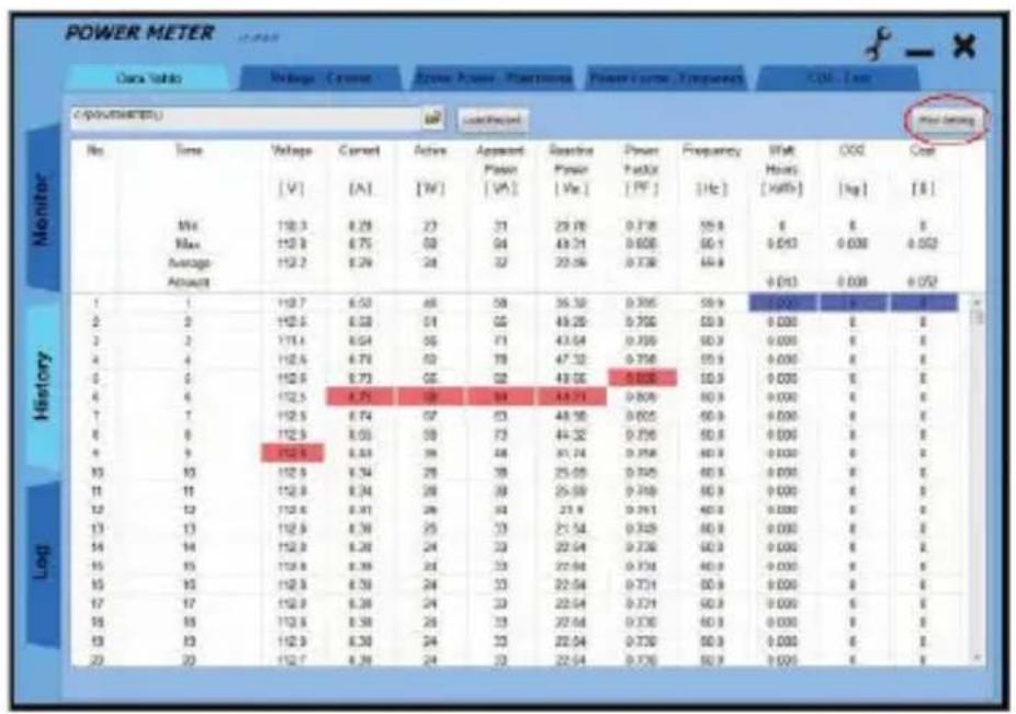
Select the "History" and "select history test data file on PC disk" and press the "Load Record" button.

other
POWER METER Data Values Voltage Current Active Power Power Measurement Power Factor Frequency CO2 Case C (approximate) No Time Voltage Current Active Apparent Baseline Power Supply Frequency Wall OOC Cost V [V] [A] [W] [V] [V] [P] [Hz] [Hz] [kWh] [kg] [L] Monitor Max 110.3 8.29 23 31 29.70 0.718 59.8 0 0 0 Max 112.9 6.75 68 54 49.71 0.608 60.1 0.617 0.608 0.053 Average 112.7 8.29 24 32 29.59 0.738 69.9 Amount History 1 1 112.7 6.52 40 58 36.52 0.705 69.9 0.001 0 0 2 0 112.9 6.58 51 65 49.29 0.705 59.9 0.000 0 0 3 3 111.6 6.64 58 71 43.04 0.705 60.9 0.000 0 0 4 4 112.6 6.73 62 79 47.32 0.706 59.9 0.000 0 0 5 5 112.9 6.73 65 82 49.05 0.706 59.9 0.000 0 0 6 6 112.5 6.75 58 84 43.31 0.806 60.9 0.000 0 0 7 7 112.5 6.74 67 83 48.58 0.805 60.9 0.000 0 0 8 8 112.9 6.83 58 73 44.32 0.756 60.9 0.000 0 0 9 9 112.8 6.81 56 48 41.24 0.758 60.9 0.000 0 0 10 11 112.9 6.54 58 78 25.65 0.745 60.9 0.000 0 0 11 11 112.9 6.34 59 79 25.69 0.749 60.9 0.000 0 0 12 12 112.8 6.81 56 53 23.8* 0.761 60.9* 0.000 * * * * * * * * * * * * * * * * * * * * * * * * * * * * * * * * * * * * * * * * * * * * 1310-2-3. Data Collection on Log mode
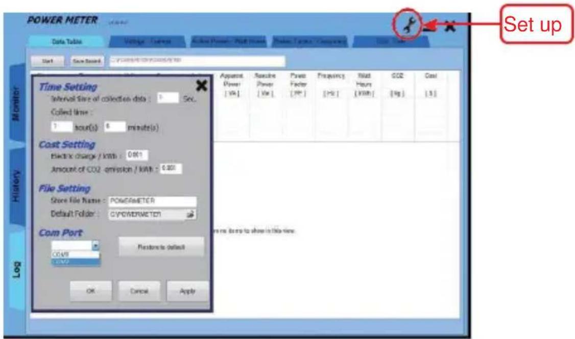
Click on "tools set up" and enter the appropriate communication and default settings.
text_image
POWER METER Data Table Voltage - Voltage Active Power - Full Power Power Tages - Currenting Start Save Record POWER METER (10000V/1000V) Time Setting Interval Time of collection data : 5 Sec. Colored time : 7 hour(s) 6 minute(s) Cost Setting Electric charge / kWh : 0.001 Amount of CO2 emission / kWh : 0.000 File Setting Store File Name : POWERMETER Default Folder : C/POWERMETER Com Port COAST C/C/C Placebo is default OK Cancel Apply Apparent Power [Vdc] Reverse Power [Vw] Power Factor [Pc] Frequency [Hz] Initial Hours [kWh] CO2 [kg] Cost [S] Set up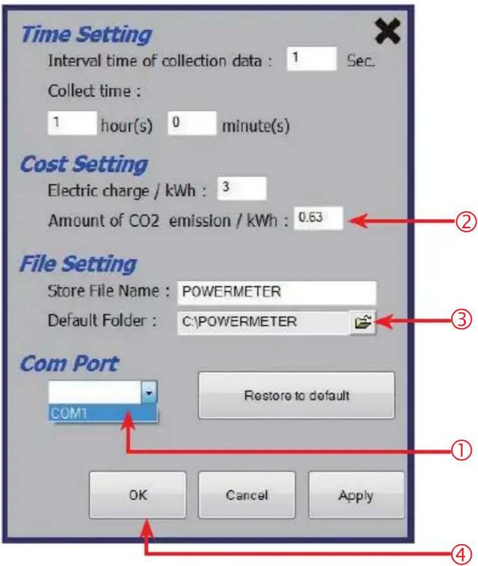
text_image
Time Setting Interval time of collection data : 1 Sec. Collect time : 1 hour(s) 0 minute(s) Cost Setting Electric charge / kWh : 3 Amount of CO2 emission / kWh : 0.63 File Setting Store File Name : POWERMETER Default Folder : C:\POWERMETER Com Port COM1 Restore to default OK Cancel Apply ① ② ③ ④① Click on the "Com Port" and select the RS 232 port number.(select a created port number.)
② Set an electric charge per 1 kWh, and a CO2 emission.
③ File Setting.
④ When all setting has done, Press "OK" button.
10-3. Data analysis (Monitor/History/Log data analysis)
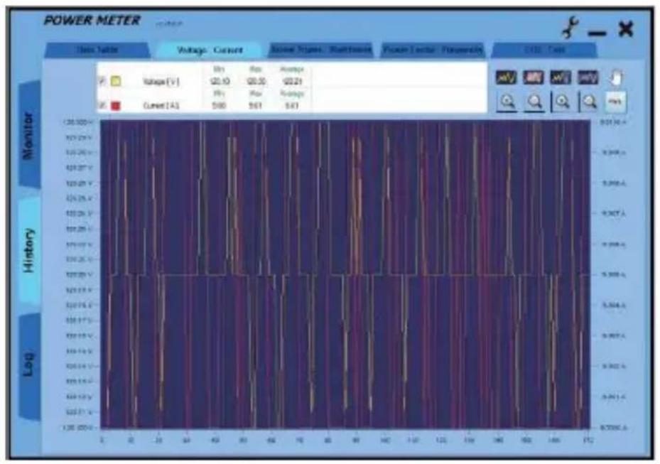
10-3-1. Test data analysis-voltage and current
When the "Voltage-Current" tab is pressed, the voltage and current analysis and graph will be displayed.
Analysis:
| Min | Max | Average | ||
| ✓ | Voltage [V] | 120.10 | 120.30 | 120.21 |
| Min | Max | Average | ||
| ✓ | Current [A] | 9.00 | 9.01 | 9.01 |
Graph:
bar
POWER METER | Data Table | Voltage (V) | Current (A) | Amplitude | | :--- | :--- | :--- | :--- | | Monator | 20.10 | 20.30 | 62.21 | | History | 5.88 | 5.61 | 5.67 | | Log | 0.90 | 0.90 | 0.90 |10-3-2. Test data analysis-voltage active power and watt hours mode
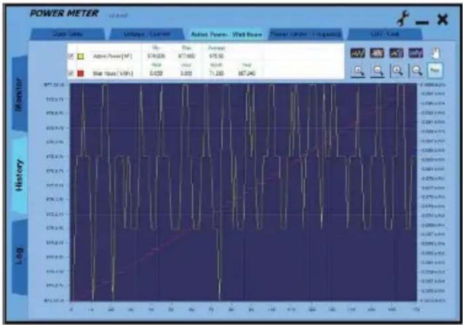
When the "Active Power-Watt Hours" tab is pressed, the active power and watt hours analysis and graph will be displayed.
Analysis:
| Min | Max | Average | |||
| √ | Active Power [W] | 974.000 | 977.000 | 975.90 | |
| Real | Hour | Month | Year | ||
| √ | Watt Hours [kWh] | 0.099 | 0.099 | 71.280 | 867.240 |
Graph:
10-3-3. Test data analysis-power factor and frequency mode
When the "Power Factor-Frequency" tab is pressed, the power factor and frequency analysis and graph will be displayed.
Analysis:
| Min | Max | Average | ||
| ✓ | Power Factor [ PF ] | 0.90 | 0.90 | 0.90 |
| Min | Max | Average | ||
| ✓ | Frequency [ Hz ] | 49.80 | 50.10 | 49.95 |
Graph:

bar
POWER METER | Category | Power Factor (FP) | Frequency (Hz) | | :--- | :--- | :--- | | Monitor | 0.9123 | 0.000 | | History | 0.8476 | 0.000 | | Log | 0.8476 | 0.000 |10-3-4. Test data analysis-CO2 and cost
When the "CO2-Cost" tab is pressed, the CO2 and cost analysis and graph will be displayed.
Analysis:
| Real | Hour | Month | Year | ||
| √ | CO2 [kg] | 0.297 | 0.297 | 213.840 | 2601.720 |
| Real | Hour | Month | Year | ||
| √ | Cost [$] | 0.495 | 0.495 | 356.400 | 4336.200 |
Graph:

line
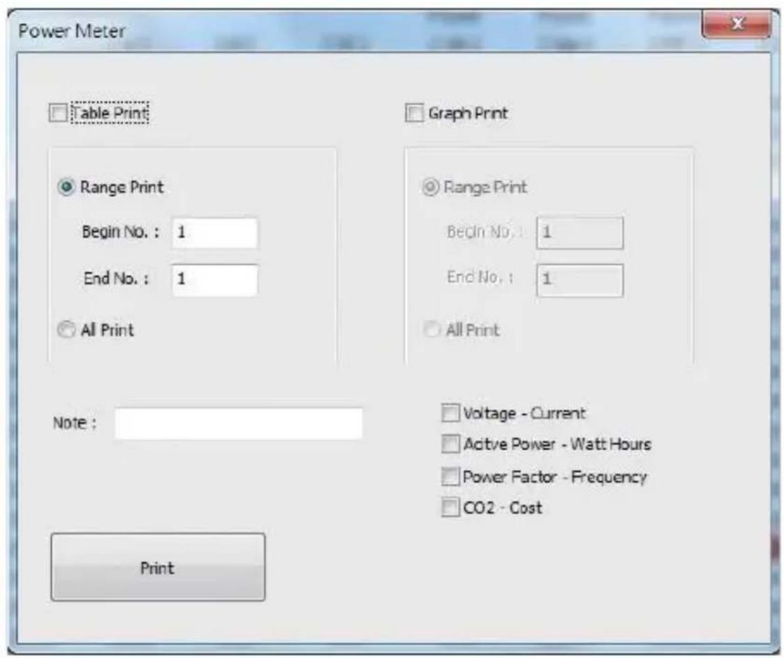
| Measurement | CO2 (kg) | Total | Hour | Mean | Year | |---|---|---|---|---|---| | Monitor | 6.257 | 6.257 | 0.297 | 265.040 | 289.738 | | History | 6.495 | 6.495 | 0.495 | 296.408 | 4306.388 | | Lag | 5.498 kg | 5.498 kg | 5.498 kg | 5.498 kg | 5.498 kg |10-4. Print Setting (On History Mode)
Press "Print Setting" button can show table print and graph print setting.

bar
| Measurement | Value | |-------------|-------| | V1 | 20.93 | | V2 | 20.95 | | V3 | 20.21 | | V4 | 8.80 | | V5 | 8.81 | | V6 | 8.87 |Printing set-up:
text_image
Power Meter Table Print Range Print Begin No. : 1 End No. : 1 All Print Note : Print Graph Print Range Print Begin No. : 1 End No. : 1 All Print Voltage - Current Active Power - Watt Hours Power Factor - Frequency CO2 - Cost14 Contact
If you have any questions, suggestions or technical problems, please do not hesitate to contact us. You will find the relevant contact information at the end of this user manual.
15 Disposal
For the disposal of batteries in the EU, the 2006/66/EC directive of the European Parliament applies. Due to the contained pollutants, batteries must not be disposed of as household waste. They must be given to collection points designed for that purpose.
In order to comply with the EU directive 2012/19/EU we take our devices back. We either re-use them or give them to a recycling company which disposes of the devices in line with law.
For countries outside the EU, batteries and devices should be disposed of in accordance with your local waste regulations.
If you have any questions, please contact PCE Instruments.

text_image
Pb www.pce-instruments.com
PCE Instruments contact information
Germany
Chester Rd, Old Trafford Manchester
M32 0RS
United Kingdom
Tel: +44 (0) 161 464902 0
Fax: +44 (0) 161 464902 9
info@pce-instruments.co.uk www.pce-
instruments.com/english
The Netherlands
PCE Brookhuis B.V. Institutenweg 15
7521 PH Enschede
Nederland
Telefoon: +31 (0)53 737 01 92
info@pcebenelux.nl
www.pce-instruments.com/dutch
France
PCE Instruments France EURL
United States of America
PCE Americas Inc.
1201 Jupiter Park Drive, Suite 8
Jupiter / Palm Beach
33458 FL
USA
Tel: +1 (561) 320-9162
Fax: +1 (561) 320-9176
info@pce-americas.com
www.pce-instruments.com/us
Spain
PCE Ibérica S.L.
Calle Mula, 8
02500 Tobarra (Albacete)
España
Tel.: +34 967 543 548
Fax: +34 967 543 542
info@pce-iberica.es
www.pce-instruments.com/espanol
Turkey
Pehlivan Sok. No.6/C
www.pce-instruments.com/turkish
Denmark
PCE Instruments Denmark ApS
Birk Centerpark 40
7400 Herning
Denmark