DC 50 - Measurement PCE Instruments - Free user manual and instructions
Find the device manual for free DC 50 PCE Instruments in PDF.

User questions about DC 50 PCE Instruments
0 question about this device. Answer the ones you know or ask your own.
Ask a new question about this device
Download the instructions for your Measurement in PDF format for free! Find your manual DC 50 - PCE Instruments and take your electronic device back in hand. On this page are published all the documents necessary for the use of your device. DC 50 by PCE Instruments.
USER MANUAL DC 50 PCE Instruments
text_image
PCE OFF 49973 5078 CLAMP METERUser Manual
PCE-DC 50 AC / DC Clamp Meter

text_image
QR code image containing encoded data, no visible human-readable textUser manuals in various languages (français, italiano, español, português, nederlands, türk, polski, русский, 中文) can be found by using our product search on: www.pce-instruments.com
Last change: 17 January 2022
v1.0
Contents
1 Safety notes.... 1
2 Specifications.... 2
3 Delivery scope....4
4 System description....5
5 Operation 6
5.1 Preparation 6
5.2 Shutter for input sockets....7
5.3 Non-contact voltage detection 7
5.4 Current measurement AC / DC....7
5.5 Voltage measurement AC / DC 8
5.6 Resistance measurement, continuity and diode test....8
5.7 Capacitance measurement....9
5.8 Frequency and duty cycle....9
5.9 μA current measurement AC / DC 9
5.10 Temperature measurement....9
6 Function setting 10
6.1 Freeze measured value....10
6.2 MIN / MAX....10
6.3 Hold peak value....10
6.4 Set measurement range....10
6.5 Display backlight....10
6.6 Measuring spot illumination....10
6.7 Bluetooth connection....10
6.8 Automatic power off....11
7 Maintenance and cleaning .... 11
7.1 Cleaning....11
7.2 Battery replacement....11
7.3 Fuse replacement ....11
8 Contact....12
9 Disposal 12
1 Safety notes
Please read this manual carefully and completely before you use the device for the first time. The device may only be used by qualified personnel and repaired by PCE Instruments personnel.
Damage or injuries caused by non-observance of the manual are excluded from our liability and not covered by our warranty.
- The device must only be used as described in this instruction manual. If used otherwise, this can cause dangerous situations for the user and damage to the meter.
- The instrument may only be used if the environmental conditions (temperature, relative humidity, ...) are within the ranges stated in the technical specifications. Do not expose the device to extreme temperatures, direct sunlight, extreme humidity or moisture.
- Do not expose the device to shocks or strong vibrations. Never touch live components when measuring. There is a danger to life.
• Never touch the bare measuring tips, otherwise electric shocks may occur.
- Before each measurement, make sure that the correct measurement range is set and that the test leads are connected correctly.
- Resistance, capacitance and temperature measurements as well as diode tests (if applicable) may only be carried out in a voltage-free state.
- Before replacing the batteries or the fuses, all test leads must be removed from the meter.
- The case should only be opened by qualified PCE Instruments personnel.
- Never use the instrument when your hands are wet.
- You must not make any technical changes to the device.
- The appliance should only be cleaned with a damp cloth. Use only pH-neutral cleaner, no abrasives or solvents.
- The device must only be used with accessories from PCE Instruments or equivalent.
- Before each use, inspect the case for visible damage. If any damage is visible, do not use the device.
- Do not use the instrument in explosive atmospheres.
- The measurement range as stated in the specifications must not be exceeded under any circumstances.
- Non-observance of the safety notes can cause damage to the device and injuries to the user.
| General warning signNon-observance can cause damage to the device and injuries to the user. | |
| Warning: electrical voltageNon-observance can cause electric shock. |
We do not assume liability for printing errors or any other mistakes in this manual.
We expressly point to our general guarantee terms which can be found in our general terms of business.
If you have any questions please contact PCE Instruments. The contact details can be found at the end of this manual.
2 Specifications
| Current measurement AC/DC (current clamp) | ||
| Measurement range | Resolution | Accuracy |
| 0.00 ... 50.00 A | 10 mA | ±2.5 % + 5 digits |
| 0.0 ... 1000.0 A | 0.1 A | ±2.5 % + 5 digits |
| For AC current measurement, the accuracies refer to 50 ... 60 Hz and 5 ... 100 % of the measurement range. | ||
| Current measurement AC/DC (test leads) | ||
| Measurement range | Resolution | Accuracy |
| 0.00 ... 500.00 μA | 0.01 μA | DC: ±(1.0 % + 6 digits) |
| AC: ±(1.5 % + 30 digits) | ||
| 0.0 ... 5000.0 μA | 0.1 μA | DC: ±(1.0 % + 6 digits) |
| AC: ±(1.5 % + 30 digits) | ||
| Voltage measurement AC/DC | ||
| Measurement range | Resolution | Accuracy |
| 0.00 ... 500.00 mV | 0.01 mV | DC: ±(0.1 % + 3 digits) |
| 0.0000 ... 5.0000 V | 0.0001 V | AC: ±(1.0 % + 30 digits) |
| 0.000 ... 50.000 V | 0.001 V | |
| 0.00 ... 500.00 V | 0.01 V | |
| 0.0 ... 600.0 V | 0.1 V | |
| For AC voltage measurement, the accuracies refer to 50 ... 1000 Hz and 5 ... 100 % of the measurement range. | ||
| Resistance measurement | ||
| Measurement range | Resolution | Accuracy |
| 0.00 ... 500.00 Ω | 0.01 Ω | ±(1.0 % + 9 digits) |
| 0.0000 ... 5.0000 kΩ | 0.0001 kΩ | ±(1.0 % + 5 digits) |
| 0.000 ... 50.000 kΩ | 0.001 kΩ | ±(1.0 % + 5 digits) |
| 0.00 ... 500.00 kΩ | 0.01 kΩ | ±(1.0 % + 5 digits) |
| 0.0000 ... 5.0000 MΩ | 0.0001 MΩ | ±(2.0 % + 10 digits) |
| 0.000 ... 50.000 MΩ | 0.001 MΩ | ±(3.0 % + 10 digits) |
| Capacity measurement | ||
| Measurement range | Resolution | Accuracy |
| 0.00 ... 500.00 nF | 0.01 nF | ±(3.5 % + 40 digits) |
| 0.0 ... 5000.0 nF | 0.1 nF | ±(3.5 % + 10 digits) |
| 0.00 ... 50.00 μF | 0.01 nF | ±(3.5 % + 10 digits) |
| 0.0 ... 500.0 μF | 0.1 μF | ±(3.5 % + 10 digits) |
| 0.000 ... 5.000 mF | 0.001 mF | ±(2.0 % + 10 digits) |
| Frequency measurement | ||
| Measurement range | Resolution | Accuracy |
| 0.000 ... 50.000 Hz | 0.001 Hz | |
| 0.00 ... 500.00 Hz | 0.01 Hz | |
| 0.0000 ... 5.000 kHz | 0.0001 kHz | |
| 0.000 ... 50.000 kHz | 0.001 kHz | ±(0.3 % + 2 digits) |
| 0.00 ... 50.00 kHz | 0.01 kHz | |
| 0.0000 ... 5.0000 MHz | 0.0001 | |
| 0.000 ... 10.000 MHz | 0.001 | |
| Duty cycle | ||
| Measurement range | Resolution | Accuracy |
| 5 % ... 95 % | 0.10 % | ±(1 % + 2 digits) |
| Pulse width: 100 μs ... 100 ms | ||
| Frequency: 10 Hz ... 10 kHz | ||
| Temperature | ||
| Measurement range | Resolution | Accuracy (of rdg.) |
| -100 °C ... 1000 °C | 0.1 | ±(1 % + 2.5 °C) |
| General technical specifications of the clamp meter PCE-DC 50 | |
| Maximum cable diameter | max. 48 mm |
| Display | two-line, 50,000 digits |
| Continuity test | 50 ohms |
| <50 mA | |
| Diode test | 0.3 mA |
| 2.8 V DC | |
| Battery indicator | battery icon when battery level is low |
| Overrange | OL when measurement range exceeded |
| Sampling rate | 2 Hz |
| Peak detection | >1 ms |
| Thermocouple | Type K |
| Fuse | 500 mA ceramic, fast-acting |
| AC bandwidth (AC A / AC V) | 50 Hz ... 400 Hz |
| AC measurement | True RMS |
| Operating conditions | 5 °C ... 40 °C / 41 ... 104°F |
| max. 80 % RH at 31 °C | |
| Storage conditions | -20 °C ... 60 °C / -4 ... 140°F |
| max. 80 % RH | |
| Power supply | 9 V block battery |
| Automatic power off | after approx. 30 minutes |
| Interface | Bluetooth |
| Dimensions (W x H x D) | 230 x 76 x 40 mm / 9 x 3 x 1.6" |
| Weight | 315 g |
| Safety | IEC 1010-1(2001): EN 61010-1(2001) |
| CAT III 600 V | |
| CAT II 1000 V | |
| Pollution degree 2 | |
3 Delivery scope
1 x PCE-DC 50 clamp meter, 1 x test lead set, 1 x carrying case, 1 x PC software, 1 x Bluetooth adaptor, 2 x K-type thermocouple, 1 x 9 V block battery
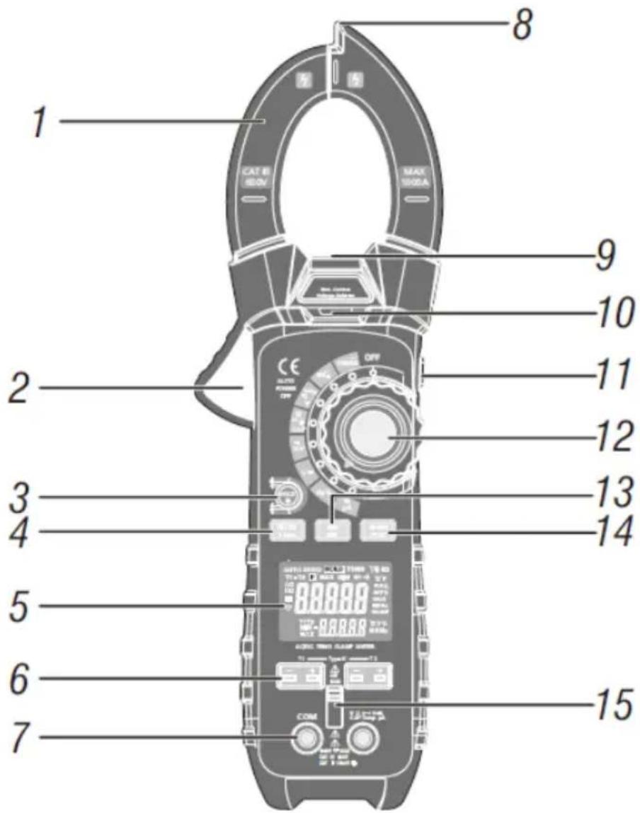
4 System description
text_image
1 CAT B 600V MAX 500A 2 9 10 11 12 3 13 4 14 5 6 7 8 COM COM COM COM COM① Current clamp
② Opening lever current clamp
③ HOLD key / display backlight
④ MODE / Bluetooth key
⑤ Display
⑥ Sockets for K-type thermocouple
⑦ Sockets for test lead
⑧ Sensor non-contact voltage detection
⑨ Illumination of measuring location
⑩ Indicator non-contact voltage detection
⑪ ZERO key / illumination
⑫ Function rotary switch
⑬ MAX / MIN key
⑭ RANGE / PEAK key
⑮ Shutter for input sockets

text_image
AUTO ZERO HOLD TRMS T1-T2 P MAX MIN + · · · · · · °C°F AC 0.0000 DC 0.0000 T1T2 MIN - 0.0000 MAX 0.0000 mμA mV% MKΩ MKHz munF °C°F% MKHz| Icon | Description | Icon | Description |
| HOLD | Freeze measured value | Ω | Resistance |
| Automatic power off | A | Ampere (current) | |
| AUTO | Automatic measurement range adjustment | F | Farad (capacity) |
| Show peak value | Hz | Hertz (frequency) | |
| DC | Direct current | % | Duty cycle |
| AC | Alternating current | °F and °C | Temperature unit |
| MAX | Maximum value | T1, T2, T1-T2 | Temperature input 1 and 2 / difference |
| MIN | Minimum value | n, m,μ, M, k | Measured value sign |
 | Battery low | Continuity test | |
| ZERO | Zeroing DC and capacitance | Diode test | |
| mV or V | milli-volts or volts |
5 Operation
5.1 Preparation
- Unpack the meter completely.
- Remove the protective foils if necessary.
- Insert a battery as described in chapter 7.2.2.
5.2 Shutter for input sockets
The shutter prevents the simultaneous connection of the test leads for the multimeter function and the connection of the thermocouples for temperature measurement. Slide the switch upwards to use the multimeter function. To use the temperature measurement function, slide the switch down.
Attention!
The shutter is a safety feature that prevents dangerous contact voltages. The meter must not be operated if the shutter is defective.

text_image
Technical diagram showing two views of a device's front panel with labeled buttons and ports, including 'COM' and 'CCAM' labels.5.3 Non-contact voltage detection
- Turn the function rotary switch to any position.
- Place the tip on the conductor to be tested. In case of multi-core conductors, run the tip along the conductor to exclude false measurements due to twisted conductors.
- If voltage is present, the indicator for non-contact voltage detection permanently glows in red.
5.4 Current measurement AC / DC
Remove all test leads from the meter before making measurements with the clamp.
- Turn the rotary function switch to the 1000 A AC/DC position.
- Use the MODE key to select between AC and DC.
- Open the measuring clamp, enclose the conductor to be measured and close the clamp completely.
- If the read value is below 50 A, turn the rotary switch to 50 A AC/DC to improve the resolution.

natural_image
Two identical line drawings of a flat-tinted clamp meter with no visible text or symbols5.4.1 Zeroing DC
With this function, you can set the measured value display to zero.
• As described in chapter 5.4, select current measurement DC.
- Press the "ZERO" key on the right side of the meter.
• The display should now show 0000. A slight jump of the last digit is normal.
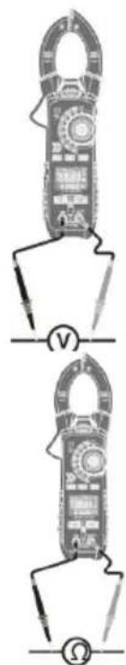
5.5 Voltage measurement AC / DC
Do not make a voltage measurement while a motor is being switched on or off in the circuit. This can cause voltage peaks and damage the meter.
- Slide the cover of the input sockets upwards.
- Set the rotary switch to position V.
- Use the MODE key to select between AC and DC.
- Plug the test leads into the measuring input sockets (black to COM and red to V).
- Touch the measuring spots with the measuring tips.
- Read the measured value in the display.
5.6 Resistance measurement, continuity and diode test
Disconnect the circuits / components to be measured from the power supply.
5.6.1 Resistance
- Slide the cover of the input sockets upwards.
- Set the rotary switch to position .
- Plug the test leads into the measuring input sockets (black to COM and red to ).
- Touch the measuring spots with the measuring tips.
- Read the measured value in the display.
5.6.2 Continuity test
- Slide the cover of the input sockets upwards.
- Set the rotary switch to position .
- Press the MODE key repeatedly until the continuity test icon appears on the display.
• Plug the test leads into the measuring input sockets (black to COM and red to Ω). - Touch the measuring points with the measuring tips.
- An acoustic signal sounds if the resistance is < 50 .
5.6.3 Diode test
- Slide the cover of the input sockets upwards.
- Set the rotary switch to position .
- Press the MODE key repeatedly until the diode test icon appears on the display.
• Plug the test leads into the measuring input sockets (black to COM and red to Ω). - Touch the measuring spots with the measuring tips and write down the measured value.
- Swap the polarity.
• Now compare this reading to the first reading.
Evaluate the measurement as follows: If "OL" is displayed in both measurements, the diode is defective. If "OL" is displayed in one measurement and typical values of e.g. 0.400 V ... 1.800 V are displayed in the second measurement, the diode is working. If voltage values are displayed in both measurements, the diode is defective. In this case, the diode generates a short circuit.
natural_image
Technical line drawing of a mechanical device with labeled components and electrical connections (no text or symbols)5.7 Capacitance measurement
- Slide the cover of the input sockets upwards.
- Set the rotary switch to position .
- Press the MODE key repeatedly until "F" appears on the display.
- Plug the test leads into the measuring input sockets (black to COM and red to ).
- Touch the measuring spots with the measuring tips.
- Read the measured value.
The stabilisation of the measured value can take several seconds for larger measured values.

natural_image
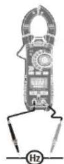
Pure electrical circuit lines without any symbols5.8 Frequency and duty cycle
- Slide the cover of the input sockets upwards.
- Set the rotary switch to position Hz.
- Plug the test leads into the measuring input sockets black to COM and red to CAP).
- Touch the measuring spots with the measuring tips.
Read the measured values in the display (frequency in the middle / duty cycle at the bottom).
5.9 μA current measurement AC / DC
- Slide the cover of the input sockets upwards.
- Set the rotary switch to position A.
- Use the MODE key to select AC or DC.
- Plug the test leads into the measuring input sockets (black to COM and red to A).
- Touch the measuring spots with the measuring tips.
- Read the measured value in the display.
5.10 Temperature measurement
- Slide the cover of the input sockets downwards.
- Set the rotary switch to position Temp.
- Use the MODE key to select °C or °F.
- Plug the thermocouple(s) into the measuring input sockets.
- Place it/them at the desired measuring spots.
- Read the measured value in the display.
A measured value overflow or unconnected temperature sensor is indicated in the
display by "OL". During the T1-T2 measurement, a missing sensor is signalled by ---- in the main display.
With the RANGE key, you can choose between different types of displaying the measured values:
| Key | Display | |
| RANGE | Middle | Bottom |
| T1 | T2 | |
| 1 x | T2 | T1 |
| 2 x | T1-T2 | T1 |
| 3 x | T1- T2 | T2 |
natural_image
Illustration of a handheld electronic device with a labeled 'Hz' indicator (no text or symbols on the device itself)
natural_image
Diagram of a handheld electrical clamp device with circuitry and battery (no text or symbols)
6 Function setting
6.1 Freeze measured value
- Press the HOLD kry to freeze the current readings on the display. HOLD" appears in the display.
- Press again to return to measuring mode.
6.2 MIN / MAX
- Press the MAX / MIN key to activate the max/min memory. The display shows the current and the maximum measured value.
- Press the MAX / MIN key again. The display shows the current and the minimum measured value.
- Press the MAX / MIN key again. The display shows "Max / Min" and the current measured value (only available for the measuring functions temperature and frequency). The min and max values are saved in the background.
- Press and hold the MAX / MIN key to exit the function.
6.3 Hold peak value
With the hold peak function, you can display the max. and min. value of the sine wave in the V AC measuring function.
- Press and hold the RANGE key to switch the function on or off.
6.4 Set measurement range
You can influence the measurement ranges for the measuring functions voltage, resistance, capacitance, frequency and A. The default setting is automatic measurement range change.
- Press the RANGE key repeatedly until the appropriate measurement range is set.
- Press and hold the RANGE key to return to automatic range selection.
6.5 Display backlight
Press and hold the HOLD key to turn the backlight on or off.
(Depending on the firmware version, the display backlight switches off automatically after 30 seconds.)
6.6 Measuring spot illumination
Press and hold the ZERO key to switch the measuring spot illumination on or off.
6.7 Bluetooth connection
Press and hold the MODE key to switch the Bluetooth connection on or off.
For use on the PC, download the PCE-DC 50 software from our download area: https://www.pce-instruments.com/english/download-win_4.htm
Use the dongle from the delivery scope as the Bluetooth interface.
The "Meterbox Pro" app is available in app stores for connection to mobile devices.
6.8 Automatic power off
The automatic power off function switches the meter off after 30 minutes. To switch on again, turn the rotary switch to the "OFF" position and then back to the desired measuring function.
6.8.1 Disable function
- When the meter is switched off, hold down the MODE key and switch on the meter with the rotary switch.
• The display shows "APO d". - Release the MODE key.
• The function is active until manual power off. The icon is hidden.
7 Maintenance and cleaning
Disconnect the meter from electrical circuits for maintenance and cleaning. Remove the test leads or temperature probes from the meter.
If you do not use the instrument for more than 60 days, remove the batteries.
7.1 Cleaning
Wipe the meter regularly with a damp cloth.
7.2 Battery replacement
7.2.1 Battery indicator
Replace the battery as soon as the icon appears.
7.2.2 Replacing the battery
- Loosen the screw of the battery compartment cover.
- Open the battery compartment and remove the used battery.
- Connect a new battery (9 V block), observing correct polarity.
- Close the battery compartment and fasten the locking screw.
7.3 Fuse replacement
- Loosen the screw of the battery compartment cover.
- Open the battery compartment and replace the defective fuse. (500 mA, 660 V, fast-acting)
- Close the battery compartment and fasten the locking screw.
8 Contact
If you have any questions, suggestions or technical problems, please do not hesitate to contact us. You will find the relevant contact information at the end of this user manual.
9 Disposal
For the disposal of batteries in the EU, the 2006/66/EC directive of the European Parliament applies. Due to the contained pollutants, batteries must not be disposed of as household waste. They must be given to collection points designed for that purpose.
In order to comply with the EU directive 2012/19/EU we take our devices back. We either re-use them or give them to a recycling company which disposes of the devices in line with law.
For countries outside the EU, batteries and devices should be disposed of in accordance with your local waste regulations.
If you have any questions, please contact PCE Instruments.

text_image
Pb CE www.pce-instruments.com
PCE Instruments contact information
Germany France Spain
PCE Deutschland GmbH PCE Instruments France EURL PCE Ibérica S.L.
Im Langel 26 23, rue de Strasbourg Calle Mayor, 53
D-59872 Meschede 67250 Soultz-Sous-Forets 02500 Tobarra (Albacete)
Unit 11 Southpoint Business Park
Ensign Way, Southampton
Hampshire
United Kingdom, SO31 4RF
Tel: +44 (0) 2380 98703 0
Fax: +44 (0) 2380 98703 9
info@pce-instruments.co.uk
www.pce-instruments.com/english
Italy
PCE Italia s.r.l.
Via Pesciatina 878 / B-Interno 6
55010 Loc. Gragnano Pehlivan Sok. No.6/C
Capannori (Lucca)
Italia
www.pce-instruments.com/turkish
The Netherlands
PCE Brookhuis B.V.
Institutenweg 15
7521 PH Enschede
Nederland
Telefoon: +31 (0)53 737 01 92
info@pcebenelux.nl
www.pce-instruments.com/dutch Fax: +1 (561) 320-9176
info@pce-americas.com
www.pce-instruments.com/us