UATYQ45ABAY1 - Air Conditioning DAIKIN - Free user manual and instructions
Find the device manual for free UATYQ45ABAY1 DAIKIN in PDF.

User questions about UATYQ45ABAY1 DAIKIN
0 question about this device. Answer the ones you know or ask your own.
Ask a new question about this device
Download the instructions for your Air Conditioning in PDF format for free! Find your manual UATYQ45ABAY1 - DAIKIN and take your electronic device back in hand. On this page are published all the documents necessary for the use of your device. UATYQ45ABAY1 by DAIKIN.
USER MANUAL UATYQ45ABAY1 DAIKIN
Rooftop Packaged Unit
text_image
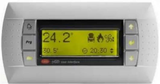
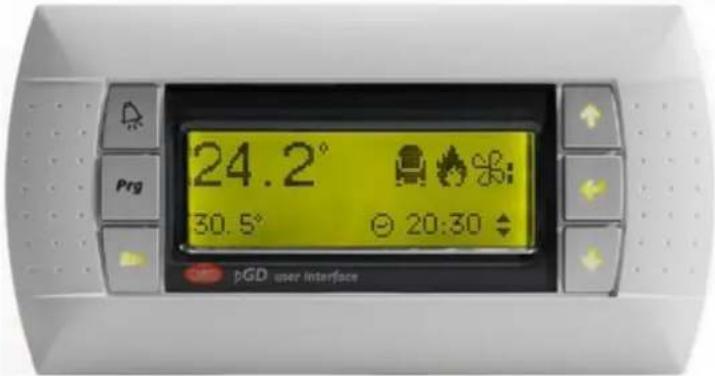
24.2° 30.5° 20:30 PGD user interfaceModels:
UATYQ20ABAY1
UATYQ25ABAY1
UATYQ30ABAY1
UATYQ45ABAY1
UATYQ50ABAY1
UATYQ55ABAY1
UATYQ65ABAY1
UATYQ75ABAY1
UATYQ90ABAY1
UATYQ110ABAY1
UATYQ115ABAY1
UATYQ20AFC2Y1
UATYQ25AFC2Y1
UATYQ30AFC2Y1
UATYQ45AFC2Y1
UATYQ50AFC2Y1
UATYQ55AFC2Y1
UATYQ65AFC2Y1
UATYQ75AFC2Y1
UATYQ90AFC2Y1
UATYQ110AFC2Y1
UATYQ115AFC2Y1
UATYQ20AFC3Y1
UATYQ25AFC3Y1
UATYQ30AFC3Y1
UATYQ45AFC3Y1
UATYQ50AFC3Y1
UATYQ55AFC3Y1
UATYQ65AFC3Y1
UATYQ75AFC3Y1
UATYQ90AFC3Y1
UATYQ110AFC3Y1
UATYQ115AFC3Y1
Operation manual
Rooftop Packaged Unit
English

natural_image
Blank grid paper with uniform gray squares on white background (no text or symbols)Contents
1 User Interface 4
2 Operating guide 5
2.1 Software menu 5
2.2 Main mask and menu 6
2.3 Switching ON/OFF he unit from keyboard 7
2.4 Temperature and air flow setpoint adjust 7
2.5 Clock menu and time slots setting 8
2.5.1 Time slots programming examples 9
2.6 Stop washing function (forced freecooling at unit start-up) 10
2.7 Summer/winter changeover from keyboard 11
2.8 Input/output visualization 12
2.9 Change language and unit and software data visualization 14
2.10 Alarms
15
This operation manual is dedicated to the end user of the unit and it contains a brief description of all free access functions of the unit control.
1 USER INTERFACE
The user interface is a LCD display with 4 rows, 20 columns and automatic backlight; the display has 6 function keys, that are used to navigate the software menu and to set the parameters.
text_image
24.2° 30.5° 20:30 PGD user interfaceThe key functions are described in the following.

This key, called "up arrow", allows to scroll up the masks and to modify the value of each mask field, increasing it.

This key, called "down arrow", allows to scroll up the masks and to modify the value of each mask field, decreasing it.

This key, called "Enter", confirms the selection done to access the menu branches and stores a parameter that has been modified.
This key, called "alarm", allows to display active alarms and, in case, to reset them.

This key, called "prg", allows to enter the software menu.

This key, called "esc", allows to exit the displayed mask and to go back to the previous menu level.
The operating guide describes the main control functions.
2.1 Software menu
The software is organized with a menu that allows to access to different branches, each one containing one or more masks or screens, with different access levels: free, partially password-protected or completely password-protected.
Pressing the ^Prg key from any mask, the following menu loop is displayed:
| Italiano | English | Español |
| ON/OFF unità | Unit ON/OFF | ON/OFF unidad |
| Costruttore | Manufacturer | Constructor |
| Utente | User | Usuar |
| Setpoint | Setpoint | P.Consig. |
| Orologio | Clock | Reloj |
| Ingressi/Uscite | Input/Output | Entrad/Salidas |
| Storico | History | Histor. |
| Manutenzione | Maintenance | Mantenimiento |
| Selezione unità | Unit selection | Selecc.unidad |
| Estate/Inverno | Summer/Winter | Ver./Inv. |
With arrow keys ↑ ↓ it is possible to scroll the menu; the selected one is highlighted and marked by an arrow on the left:
| MenuQ0□ Costruttore | MenuQ0□ Manufacturer | MenuQ0□ Constructor |
| → Utente | → User | → Usuar |
| □ Setpoint | □ Setpoint | □ P.Consig |
To enter the selected menu, press the "enter" key

This is the masks tree with all sub-menus:
- The ones reported in underlined letters are free access menu;
- the ones reported in "italic letters" are partially password-protected menu;
- the ones reported in bold letters are completely password-protected menu.
The access to the password-protected menu is reserved to Service technicians.

flowchart
graph TD
    A["Main mask"] --> B["M. Main menu"]
    B --> C["N. Unit ON/OFF"]
    B --> D["Z. Manufacturer"]
    D --> E["V. Initialization"]
    D --> F["C. Configuration"]
    D --> G["G. Parameters"]
    D --> H["T. Timing"]
    D --> I["Drivers"]
    I --> J["F. System EVD param."]
    I --> K["Q. Autosetup"]
    I --> L["N. Advanced settings"]
    D --> M["Y. Plug-fan"]
    B --> N["P. User"]
    B --> O["S. Setpoint"]
    B --> P["K. Clock"]
    B --> Q["I. Input/Output"]
    B --> R["History"]
    B --> S["A. Maintenance"]
    B --> T["L. Unit selection"]
    B --> U["R. Summer/Winter"]
2.2 Main mask and menu
When the unit is powered, the main mask is displayed on the unit display, showing in its first row the indoor temperature setpoint on the left and the local address of the unit on the right, in bigger fonts the read indoor temperature and on the last row the unit status on the left and the current time on the right.
| Set 27.0°C U0127.0°COFF DA TAST. 10:30 | Set 27.0°C U0127.0°COFF BY KEYB. 10:30 | Set 27.0°C U0127.0°COFF P/TECL. 10:30 |
↓ to display the unit working mode, the time slots activation, the dehumidification activation (not available), the setpoint compensation activation (where enabled).
| Unità in ESTATE M2Fasce orarie □Deumidifica □Compensazione □ | Unit in SUMMER M2Time zone □Dehumidify □Compensation □ | Unid. en VERANO M2Franj.horar. □Deshumecta □Compensación □ |
to display if the unit is in defrost, in freecooling or in freeheating mode.
| M3 | M3 | M3 | |||
| Sbrinamento | Defrost | Desescharche | |||
| Freecooling | Freecooling | Freecooling | |||
| Freeheating | Freeheating | Freeheating |
to display the unit active compressors.
| Compressore 1 □ M4 | Compressor 1 □ M4 | Compresor 1 □ M4 |
| Compressore 2 □ | Compressor 2 □ | Compresor 2 □ |
| Compressore 3 □ | Compressor 3 □ | Compresor 3 □ |
| Compressore 4 □ | Compressor 4 □ | Compresor 4 □ |
to display if high pressure alarm prevention function in summer mode is active, if the supply temperature limit is active and if the antifreeze function is enabled and active.
| Prevent □ M5Limite mandata □Antigelo - | Prevent □ M5Supply limit □Antifreeze - | Prevenc □ M5Limite impuls. □Antihiel - |
to display the delivery and return (if present) air fans working mode (manual or automatic).
| Funzionamento M6ventilatori plug-fanMandata AutomaticoRipresa Automatico | Operation M6Plug-fanDelivery AutomaticReturn Automatic | Operación M6Ventilad.Plug-fanImpulsión AutomaticoRetorno Automatico |
to display if the condensate tray electrical heater is active.
| Res.vasca cond. □ | M7Cond.tray heater □ | Res.tina cond. □ |
to display if the washing function (forced freecooling at unit start-up) is active.
| M8 | M8 | M8 | ||
| Gest.lavaggio | ☐ | Washing mng. | ☐ | Gestion lavado ☐ |
to display if the low pressure alarm prevention function in winter mode is active for circuits 1 and 2.
| Circuito 1 | M9 | Circuit 1 | M9 | Circuito 1 | M9 |
| Prevent L.P. | Prevent L.P. | Prevent L.P. | |||
| Circuito 2 | Circuit 2 | Circuito 2 | |||
| Prevent L.P. | Prevent L.P. | Prevent L.P. |
2.3 Switching ON/OFF he unit from keyboard
Prg select "On/OFF unit" menu "Enter" "Enter" to switch ON/OFF the unit.
| Stato unitàNOOFF DA TASTIERA ENTER per- ACCENDERE - | Unit statusNOOFF BY KEYBOARDPress ENTER for- SWITCH ON - | Estad unid. NOOFF POR TECLADO ENTER par- ENCEDER - |
If time slots are active, the unit will start running only if it is programmed to be ON in that time slot.
If the unit ON/OFF switching from a supervisor system is enabled, the serial consent is necessary for the effective unit starting-up.
If the unit ON/OFF switching from digital input is enabled, the ON/OFF digital input must be closed for the effective unit starting-up.
If even only one of the previous starting-up systems does not give its consent, the unit will not start running.
2.4 Temperature and air flow setpoint adjust
Prg select "Setpoint" menu "Enter".
From S0 mask, the indoor temperature setpoint in summer mode (cooling) can be adjusted: press "enter" key adjust the setpoint value with arrow keys and press again to confirm the new value.
If time slots are active, the setpoint cannot be modified from this mask, but only from the specific mask of the Clock menu.
| SetpointTemp.Est 27.0°C | S0 | Temperature setpointSum 27.0°C | S0 | P consig.Temp.Ver 27.0°C | S0 |
from S1 mask, the indoor temperature setpoint in winter mode (heating) can be adjusted: press the key adjust the setpoint value with arrow keys and press again to confirm the new value.
If time slots are active, the setpoint cannot be modified from this mask, but only from the specific mask of the Clock menu.
| Setpoint S1Temp.Inv 20.0°C | Temperature S1setpointWin 20.0°C | P consig. S1Temp.Inv 20.0°C |
from S5 mask, the delivery air flow can be adjusted: press the key , adjust the setpoint value with arrow keys and press again to confirm the new value.
The real air flow can be read from next mask S6.
| Setpoint S5 Portata aria mandata 009000m3/h | Setpoint S5 Delivery air flow 009000m3/h | PConsig. S5 Flujo aire impuls. 009000m3/h |
from S7 mask, displayed only for unit with return fans, the return air flow can be adjusted: press key, adjust the setpoint value with arrow keys and press again to confirm the new value. The real air flow can be read from next mask S8.
| Setpoint S7Portata aria ripresa008500m3/h | Setpoint S7Return air flow008500m3/h | PConsig. S7Flujo aire returno008500m3/h |
2.5 Clock menu and time slots setting
Prog select "Clock" menu .

Current time and date can be set from this mask, while the day is automatically updated.
| Orologio | KO | Clock | KO | Reloj | KO | |||
| Ora | 10:30 | Hour | 10:30 | Hora | 10:30 | |||
| Data | 01/01/18 | Date | 01/01/18 | Fech | 01/01/18 | |||
| Lunedi | Monday | Lunes | ||||||
to enable and set time slots, input the Clock menu password and press the key ← ; the factory Clock menu password is 0001.
| Inserire password0000 | K1Insert password0000 | K1Insertar password0000 | K1 |
down from this mask, the daily time slots can be enabled (second line) and switch off the unit outside the time slots (fourth line).
| Abilita fasce K2 orarie giornaliere N Abilita off unità Fascie: N | Daily time zone enable: Unit OFF by time zone enable: | K2 N | Habil.franjas horario laboral Habil. OFF unidad de franja: | K2 N |
set start and end time of the daily time slot.
| Fasce orarie giornaliere | K3 | Daily time zone | K3 | Fr. horarias diario | K3 |
| Inizio | 08:00 | Start | 08:00 | Inicio | 08:00 |
| Fine | 18:00 | Ending | 18:00 | Fin | 18:00 |
set the summer (cooling) indoor temperature setpoint inside the time slot (internal set, third line) and outside the time slot (external set, fourth line).
| Fasce orarie | K4 | Time zone | K4 | Fr. horarias | K4 |
| Funzionamento estivo | Summer working | Funcionamento verano | |||
| Set interno | 27.0°C | Internal set | 27.0°C | Set interno | 27.0°C |
| Set esterno | 30.0°C | External set | 30.0°C | Set externo | 30.0°C |
set the winter (heating) indoor temperature setpoint inside the time slot (internal set, third line) and outside the time slot (external set, fourth line).
| Fasce orarie K5Funz.invernaleSet interno 20.0°CSet esterno 16.0°C | Time zone K5Winter workingInternal set 20.0°CExternal set 16.0°C | Fr. horarias K5Func.inviernoSet interno 20.0°CSet externo 16.0°C |

nable the weekly programming, if required.
| Abilita OFF unità da fascia settimanale | K6 N | Unit OFF by week time zone enable | K6 N | Habil. OFF unid. de franja semanal | K6 N |

at week days when the unit has to be in ON status (Y) or in OFF status (N).
| Fasce orarie K7Lun N Mar N Mer NGio N Ven N Sab NDom N | Time zone K7Mon N Tue N Wed NThu N Fri N Sat NSun N | Fr. Horarias K7Lun N Mar N Mie NJue N Vie N Sab NDom N |
2.5.1 Time slots programming examples
To better explain the time slots programming, two examples are reported in the following.
Example n. 1
The unit has to operate every day:
• from 07:00 to 20:00 with summer setpoint 26.0°C and winter setpoint 21.0°C;
• from 20:00 to 07:00 with summer setpoint 30.0°C and winter setpoint 15.0°C.
Moreover, unit main fans must be always active.
Masks K2 to K6 have to be set as follows:
| Abilita fasce K2 orarie giornaliere N Abilita off unità Fascie: N | Daily time zone K2 enable: N Unit OFF by time zone enable: N | Habil.franjas K2 horario laboral N Habil. OFF unidad de franja: N |
| Fasce orarie giornaliere | K3 | Daily time zone K3 | Fr. horarias diario | K3 | |
| Inizio | 07:00 | Start | 07:00 | Inicio | 07:00 |
| Fine | 20:00 | Ending | 20:00 | Fin | 20:00 |
| Fasce orarie K4Funzionamento estivoSet interno 26.0°CSet esterno 30.0°C | Time zone K4Summer workingInternal set 26.0°CExternal set 30.0°C | Fr. horarias K4Funcionamento veranoSet interno 26.0°CSet externo 30.0°C |
| Fasce orarie K5Funz.invernaleSet interno 21.0°CSet esterno 15.0°C | Time zone K5Winter workingInternal set 21.0°CExternal set 15.0°C | Fr. horarias K5Func.inviernoSet interno 21.0°CSet externo 15.0°C |
| Abilita OFF unità da fascia settimanale | K6 N | Unit OFF by week time zone enable | K6 N | Habil. OFF unid. de franja semanal | K6 N |
It is not required to set working days on mask K7, because weekly programming is disabled from mask K6.
Example n. 2
The unit has to operate from Monday to Friday, from 07:30 to 19:30, with summer setpoint 24.0°C and winter setpoint 20.5°C; moreover, unit fans must be switched OFF from 19:30 to 07:30 and the unit has to be completely switched OFF on Saturday and Sunday.
Masks K2 to K7 have to be set as follows:
| Abilita fasce K2 orarie giornaliere N Abilita off unità Fascie: N | Daily time zone K2 enable: N Unit OFF by time zone enable: N | Habil.franjas K2 horario laboral N Habil. OFF unidad de franja: N |
| Fasce orarie giornaliere | K3 | Daily time zone K3 | Fr. horarias diario | K3 | |
| Inizio | 07:30 | Start | 07:30 | Inicio | 07:30 |
| Fine | 19:30 | Ending | 19:30 | Fin | 19:30 |
| Fasce orarie K4Funzionamento estivoSet interno 24.0°CSet esterno 30.0°C | Time zone K4Summer workingInternal set 24.0°CExternal set 30.0°C | Fr. horarias K4Funcionamento veranoSet interno 24.0°CSet externo 30.0°C |
| Fasce orarie K5Funz.invernaleSet interno 20.5°CSet esterno 15.0°C | Time zone K5Winter workingInternal set 20.5°CExternal set 15.0°C | Fr. horarias K5Func.inviernoSet interno 20.5°CSet externo 15.0°C |
| Abilita OFF unità da fascia settimanale | K6 S | Unit OFF by week time zone enable | K6 Y | Habil. OFF unid. de franja semanal | K6 S |
| Fascia oraria K7Lun S Mar S Mer SGio S Ven S Sab NDom N | Time zone K7Mon Y Tue Y Wed YThu Y Fri Y Sat NSun N | Fr. Horarias K7Lun S Mar S Mie SJue S Vie S Sab NDom N |

In case the "Unit OFF by time slot" function is enabled in mask K2, the external set in mask K4 can be whatever value, because it is not considered by the unit thermoregulation due to the fact that unit is switched OFF.
2.6 Stop washing function (forced freecooling at unit start-up)
Unit with freecooling dampers and washing function enabled.
Main mask → press "Enter" to stop washing function.
2.7 Summer/winter changeover from keyboard
The unit must be switched OFF and the summer/winter changeover from keyboard must be enabled.
Prg Select "Summer/Winter" menu "Enter"
| Unità in - ESTATE - ENTER per - INVERNO - | R0 | Unit in - SUMMER - Press ENTER for - WINTER - | R0 | Unid. en - VERANO - ENTER par - INVIERNO - | R0 |
"Enter" to change unit working mode.
If the changeover from digital input is enabled, mask R0 is not visualized.
If the automatic changeover is enabled, the changeover from winter mode to summer mode is done automatically when the indoor air temperature rises above the summer setpoint, while the changeover from summer mode to winter mode is done automatically when the indoor air temperature falls below the winter setpoint. In any case, the automatic changeover is done with the unit in ON status, so the control will first stop all active devices (compressors, electrical heaters, etc.), except main fans, and it will restart them automatically when the changeover is done, following the thermal load request.

In order to have the automatic summer/winter changeover working properly, winter setpoint must be lower than summer setpoint; if not, the control will activate an alarm that will stop the unit; this alarm will be automatically reset when the summer and winter setpoint are properly set.
2.8 Input/output visualization
Prg select "Input/Output" menu .

The mask displays intake air temperatures internal and external.
| Sonda temperatura I0 | Temperature probe I0 | Sonda temperatura I0 | |||
| Interna | 00.0°C | Intake | 00.0°C | Interna | 00.0°C |
| Esterna | 00.0°C | External | 00.0°C | Externa | 00.0°C |
the mask displays the supply air temperature.
| Sonda temperatura IlMandata 00.0°C | Temperature probe IlSupply 00.0°C | Sonda temperatura IlImpuls. 00.0°C |
the mask displays circuit 1 and 2 refrigerant pressures.
| Sonda | I3 | Probe | I3 | Sonda | I3 |
| Pressione 1 | 00.0Bar | Pressure 1 | 00.0Bar | Presión 1 | 00.0Bar |
| Pressione 2 | 00.0Bar | Pressure 2 | 00.0Bar | Presión 2 | 00.0Bar |
The mask displays the CO _2 or VOC concentration, read by the air quality probe, if present.
| Sonda I5qualità ariaCO2 0000ppm | Air quality probe I5CO2 0000ppm | Sonda I5calidad aireCO2 0000ppm |
the masks display the digital input statuses: C = closed, O = open.
| Ingressi digitali I8 | Digital input I8 | Entradas digital. I8 | |||
| 01:CCC | 07:CCC | 01:CCC | 07:CCC | 01:CCC | 07:CCC |
| 04:CCC | 10:CCC | 04:CCC | 10:CCC | 04:CCC | 10:CCC |
| Ingressi digitali I913:CCC 16:CCC | Digital input I913:CCC 16:CCC | Entradas digital. I913:CCC 16:CCC |
the mask displays the compressor statuses.
| Compressor 1 OFF Ia | Compressor 1 OFF Ia | Compressor 1 OFF Ia |
| Compressor 2 OFF | Compressor 2 OFF | Compressor 2 OFF |
| Compressor 3 OFF | Compressor 2 OFF | Compressor 3 OFF |
| Compressor 4 OFF | Compressor 4 OFF | Compressor 4 OFF |
the mask displays the statuses of the external fans and of the 4-way reversing valves of circuit 1 and 2.
| Vent.cond.1 | OFF Ib | Cond.fan 1 | OFF Ib | Vent.cond.1 | OFF Ib |
| Vent.cond.2 | OFF | Cond.fan 2 | OFF | Vent.cond.2 | OFF |
| Valv.inv.1 | OFF | Rev.valve 1 | OFF | Valv.inv.1 | OFF |
| Valv.inv.2 | OFF | Rev.valve 2 | OFF | Valv.inv.2 | OFF |

e mask displays the main fan status.
| Vent.princ. OFF Ic | Main fan OFF Ic | Vent.princ. OFF Ic |

e mask displays the electrical heater statuses, if present.
| Resistenza 1 OFF IdResistenza 2 OFF | Heater 1 | OFF Id | Resistenc. 1 | OFF Id |
| Heater 2 | OFF | Resistenc. 2 | OFF |

e mask displays the opening percentages of the external air damper and of the hot water valve, if present.
| Serr.esterna 000% IeValvola caldo 000% | Ext.damper 000% IeHeat Valve 000% | Comp.externa 000% IeVàlvula calor 000% |

e mask displays the opening percentage of the recirculation damper, if present.
| Ie2 | Ie2 | Ie2 | |||
| Serr.ricircolo | 000% | Recirc.damper | 000% | Comp.recircu. | 000% |

e mask displays the running percentage of external fans of circuit 1 and 2.
| Vent.cond.1 000% If | Vent.cond.2 000% | | Cond.fan1 | Cond.fan2 | | 000% If 000% | | Vent.cond.1 000% If | Vent.cond.2 000% | |

e mask displays the running percentage of delivery and return fans (if present).
| Vent.Plug-fan | IT | Plug-fan | IT | Vent.Plug-fan | IT |
| Segnale | Signal | Señal | |||
| Mandata | 000% | Delivery | 000% | Impuls. | 000% |
| Ripresa | 000% | Return | 000% | Retorno | 000% |

the mask displays the air pressures read from the air pressure transducer of supply and return air flow; please say that this pressure is measured on fan nozzle and is not related in any way to the available static pressure.
| Vent.Plug-fan IuSegnale sonde press.Mandata 00000PaRipresa 00000Pa | Plug-fan IuSignal pres.probeDelivery 00000PaReturn 00000Pa | Vent.Plug-fan IuSeñal sondas press.Impuls. 00000PaRetorno 00000Pa |

the masks display the evaporation temperature, the defrost calculated setpoint and the defrost starting tdown of circuits 1 and 2.
| Sbrinamento | Ivl | Defrost | Ivl | Descongelation | Ivl |
| T.evap.: | -xx.x°C | Evap.T.: | -xx.x°C | T.evap.: | -xx.x°C |
| Set sbrin.: | -xx.x°C | Defr.set.: | -xx.x°C | Set desc.: | -xx.x°C |
| Countdown: | xxx s | Countdown: | xxx s | Countdown: | xxx s |
| Sbrinamento | Iv2 | Defrost | Iv2 | Descongelation | Iv2 |
| T.evap.: | -xx.x°C | Evap.T.: | -xx.x°C | T.evap.: | -xx.x°C |
| Set sbrin.: | -xx.x°C | Defr.set.: | -xx.x°C | Set desc.: | -xx.x°C |
| Countdown: | xxx s | Countdown: | xxx s | Countdown: | xxx s |
the mask displays the NO11 auxiliary output status and the condensate tray electrical heater status.
| IzUscita aus.NO11: OFFRes.vasca cond.: OFF | IzAux.output NO11: OFFCond.tray heater:OFF | IzSalida aux.NO11: OFFRes. tina cond.: OFF |
2.9 Change language and unit and software data visualization
↓ "Maintenance" menu "Enter"
From this mask the control language can be changed, choosing from those available. Press "Enter" change the language.
| Lingua corrente AxITALIANOpremere tastoENTER per cambiare | Current language: AxENGLISHpress ENTER tochange language | Idioma actual AXESPAÑOLpulsar teclaENTER para cambiar |
the mask displays the following unit data: serial number, factory testing date and factory tester identification code.
| Dati unità AyMatricola: 12345678Data coll.: 01/01/18Collaudatore: 0653 | Unit data AySerial n.: 12345678Test data: 01/01/18Tester: 0653 | Datos unidad AyN.de serie: 12345678Data ens.: 01/01/18Ensayador: 0653 |
the mask displays the software code, version and release date and the unit model.
the mask displays the control board bios and boot versions and release dates.
| A1 | A1 | A1 | |||||||
| Bios: | 6.44 | 08/12/17 | Bios: | 6.44 | 08/12/17 | Bios: | 6.44 | 08/12/17 | |
| Boot: | 5.02 | 30/03/13 | Boot: | 5.02 | 30/03/13 | Boot: | 5.02 | 30/03/13 | |
the mask displays the control board model and type.
| Hardware installato Scheda :pCO5+ Tipo :LARGE | A2 | Installed pCO board Board :pCO5+ Type :LARGE | A2 | Hardware instalado Tarjeta:pCO5+ Tipo :LARGE | A2 |
the mask displays the unit working hours.
the mask displays the working hours of compressors 1 and 2.
| Ore funzionamento A4 | Working hours A4 | Horas func. A4 | ||
| Comp.1 | 000000h | Compressor 1 000000h | Comp.1 | 000000h |
| Comp.2 | 000000h | Compressor 2 000000h | Comp.2 | 000000h |

e mask displays the working hours of compressors 3 and 4.
| Ore funzionamento A5 | Working hours A5 | Horas func. A5 | |||
| Comp.3 | 000000h | Compressor 3 | 000000h | Comp.3 | 000000h |
| Comp.4 | 000000h | Compressor 4 | 000000h | Comp.4 | 000000h |
2.10 Alarms
When an alarm is triggered, the red "Alarm" key is on and the alarm digital output is activated.
By pressing the "Alarm" key, the last alarm is displayed; the other active alarms can be scrolled with arrow keys.
This is an example of an alarm mask:
AL70 Sonda B9 guasta o disconnessa Sonda B9 guasta o disconnessa | AL70 B9 probe broken or disconnected B9 probe broken or disconnected | AL70 Sonda B9 averia o desconect. Sonda B9 averia o desconect. |
Each alarm is identified by a code "ALxx" and the alarm cause is described in the mask. To reset an active alarm, press and hold for at least 2 seconds the "Alarm" key; if the alarm has been successfully reset, the alarm mask disappears and, if no other alarms are active, the red "Alarm" key is switched OFF. An alarm can be reset only if the condition that has activated the alarm is not present anymore.

The manual reset of an alarm must be done only after checking the alarm cause and solving the problem that has activated the alarm.
The improper reset of an alarm can cause serious damages to the unit or to its components.
On alarm history menu, last 150 alarms are stored. When the memory is full and another alarm is activated, the oldest alarm is overwritten.
In the following, the full alarm list is reported with the main possible causes, some troubleshooting hints, the reset mode, the action on the unit and on its components.
The alarm reset mode is reported on the "RESET" column:
- A = automatic: when the alarm condition disappears, the alarm is automatically reset;
- AC = automatic controlled: the alarm is automatically reset for a limited number of attempts in a certain time, after that the reset becomes manual;
- M = manual reset from display or from supervisor: the alarm must be manually reset by display as described above or by the supervisor reset variable; for each alarm with manual reset, the reset day and time are stored on the alarm history.
In the "OFF UNIT" column, it is reported if the alarm stops the whole unit or not:
• Yes = the alarm stops the unit;
- No = the alarm does not stop the unit, but only the concerned devices
| CODE | DESCRIPTION MAIN | CAUSES CHECKS AND TROU | BLESHOOTING RESET | UNIT OFF | ITEMS OFF | |
| AL01 | Overload Compressor 1 | Intervention of the thermal protection compressor 1 | Check working conditions. | M No | Compressor 1 | |
| Check cabling, terminals and circuit breaker of the motor. | ||||||
| Check adsorbed current. | ||||||
| Check compressor discharge temperature. | ||||||
| AL02 | Overload Compressor 2 | Intervention of the thermal protection compressor 2 | Check working conditions. | M No | Compressor 2 | |
| Check cabling, terminals and circuit breaker of the motor. | ||||||
| Check adsorbed current. | ||||||
| Check compressor discharge temperature. | ||||||
| AL03 | High pressure Circuit 1 | High pressure alarm from circuit 1 (high pressure switch) | Check condensing pressure. | M | No | All compressors circuit 1 |
| Check refrigerant charge. | ||||||
| Check condensing fan/s operation | ||||||
| Check the presence of warm condensing air recycling. | ||||||
| Check condensing coil cleaning and eventually clean it. | ||||||
| Reset the high pressure switch before resetting the alarm in the controller. | ||||||
| Check the correct intervention set for the high-pressure switch. | ||||||
| AL04 | High pressure Circuit 2 | High pressure alarm from circuit 2 (high pressure switch) | Check working conditions. | M | No | All compressors circuit 2 |
| Check condensing pressure. | ||||||
| Check refrigerant charge. | ||||||
| Check condensing fan/s operation | ||||||
| Check the presence of warm condensing air recycling. | ||||||
| Check condensing coil cleaning and eventually clean it. | ||||||
| Reset the high pressure switch before resetting the alarm in the controller. | ||||||
| Check the correct intervention setting for the high-pressure switch. | ||||||
| AL05 | Antifreeze alarm Digital | input 1 open Check working conditions. A (2) No | Compressors (only cooling mode) | |||
| AL06 | High temp threshold exceeded | Indoor temperature exceeds the max value set | Check working conditions. A No None | |||
| AL07 | Low temp threshold exceeded | Indoor temperature is lower than the min value set | Check working conditions. A (2) No None | |||
| AL08 | Low pressure Circuit 1 in summer | Low pressure alarm circuit 1 from the low-pressure switch (cooling mode) | Check working conditions. | M | No | All compressors circuit 1 |
| Check evaporation pressure. | ||||||
| Check refrigerant charge | ||||||
| Check evaporation fans. | ||||||
| Check the correct intervention of the low-pressure switch. | ||||||
| AL09 | Low pressure Circuit 2 in summer | Low pressure alarm circuit 2 from the low pressure switch (cooling mode) | Check working conditions. | M | No | All compressors circuit 2 |
| Check evaporation pressure. | ||||||
| Check refrigerant charge | ||||||
| Check evaporation fans. | ||||||
| Check the correct intervention of the low-pressure switch. | ||||||
| AL10 | Low pressure Circuit 1 in winter | Low pressure alarm circuit 1 from the low pressure switch (heating mode) | Check working conditions. | M | No | All compressors circuit 1 |
| Check evaporation pressure. | ||||||
| Check refrigerant charge | ||||||
| Check evaporation fans. | ||||||
| Check the correct intervention of the low-pressure switch. | ||||||
| AL11 | Low pressure Circuit 2 in winter | Low pressure alarm circuit 2 from the low-pressure switch (heating mode) | Check working conditions. | M | No | All compressors circuit 2 |
| Check evaporation pressure. | ||||||
| Check refrigerant charge | ||||||
| Check evaporation fans. | ||||||
| Check the correct intervention of the low-pressure switch. | ||||||
| AL12 | Compressor 1 maintenance | It has been exceeded Compressor 1 operating hours threshold. | Check the compressor working conditions. | M (1) No None | ||
| AL13 | Compressor 2 maintenance | It has been exceeded Compressor 2 operating hours threshold. | Check the compressor working conditions. | M (1) No None | ||
| CODE | DESCRIPTION MAIN | CAUSES CHECKS AND TROUBLESHOOTING RESET | UNIT OFF | ITEMS OFF | ||
| AL14 | Unit Maintenance | It has been exceeded unit operating hours threshold. | Unit check up. Perform the ordinary maintenance operations. | M (1) No | No None | |
| AL15 | Main fan overload/interblock | Thermal protection ventilation fan | Check working conditions. | M Yes | All | |
| Check fans motor cabling, terminals and adsorbed current. | ||||||
| Check thermal overload switch. | ||||||
| AL16 | Filter dirty | The pressure drop across the filter measured by the differential pressure switch is higher than the set value | Clean or replace the air filters. M | No None | ||
| Calibration of the differential pressure switch for clogged filters. | M | |||||
| AL17 | Not used - - - - - | |||||
| AL18 | Flow-switch alarm | The differential air pressure switch detects a pressure (airflow) lower than the set point | Check working conditions (airflow and pressure). | M Yes | All | |
| Check working operation of the ventilation fans. | ||||||
| Check air distribution system. | ||||||
| Check the correct intervention of the airflow switch. | ||||||
| AL19 | Clock broken or not present | The clock board is defective | Reboot the controller; if alarm persists, replace the main board. | M | No | None, hourly programming not operating |
| AL20 | Summer setpoint < winter setpoint | Summer set point is lower than winter set point or winter set point is higher than summer set point and automatic changeover is enabled | Check for the correct temperature set point (cooling and heating modes). | A | Yes All | |
| AL21 | B1 probe broken or disconnected | The reading of the probe B1 (supply airflow differential pressure probe) exceeds the operative range | Check working conditions. | M | No | All components and fuctions directly related to the probe |
| Check in the controller for the correct probe reading range . | ||||||
| Check the correct reading of the probe and eventually replace it. | ||||||
| Check probe wiring and terminals. | ||||||
| Check correct functioning of the analogic input of the main board. | ||||||
| AL22 | B2 probe broken or disconnected | The reading of the probe B2 (return airflow differential pressure probe) exceeds the operative range | Check working conditions. | M | No | All components and fuctions directly related to the probe |
| Check in the controller for the correct probe reading range . | ||||||
| Check the correct reading of the probe and eventually replace it. | ||||||
| Check probe wiring and terminals. | ||||||
| Check correct functioning of the analogic input at the main board. | ||||||
| AL23 | B6 probe broken or disconnected | The reading of the probe B6 (condensing pressure circuit 2) exceeds the range | Check working conditions. | M | No | All components and fuctions directly related to the probe |
| Check in the controller for the correct probe reading range . | ||||||
| Check the correct reading of the probe and eventually replace it. | ||||||
| Check probe wiring and terminals. | ||||||
| Check correct functioning of the analogic input of the main board. | ||||||
| CODE | DESCRIPTION MAIN | CAUSES CHECKS AND TROU | BLESHOOTING RESET | UNIT OFF | ITEMS OFF | |
| AL24 | B7 probe broken or disconnected | The reading of the probe B7 (indoor air humidity) exceeds the range | Check working conditions. | M | No | All components and fuctions directly related to the probe |
| Check in the controller for the correct probe reading range . | ||||||
| Check the correct reading of the probe and eventually replace it. | ||||||
| Check probe wiring and terminals. | ||||||
| Check correct functioning of the analogic input of the main board. | ||||||
| AL25 | B4 probe broken or disconnected | The reading of the probe B4 (supply air temperature) exceeds the range | Check working conditions. | M | No | All components and fuctions directly related to the probe |
| Check in the controller for the correct probe reading range . | ||||||
| Check the correct reading of the probe and eventually replace it. | ||||||
| Check probe wiring and terminals. | ||||||
| Check correct functioning of the analogic input of the main board. | M | No | All components and fuctions directly related to the probe | |||
| AL26 | B3 probe broken or disconnected | The reading of the probe B3 (condensing pressure circuit 1) exceeds the range | Check working conditions. | |||
| Check in the controller for the correct probe reading range . | ||||||
| Check the correct reading of the probe and eventually replace it. | ||||||
| Check probe wiring and terminals. | ||||||
| Check correct functioning of the analogic input of the main board. | ||||||
| AL27 | B8 probe broken or disconnected | The reading of the probe B8 (Outdoor air temperature) exceeds the range | Check working conditions. | M | No | All components and fuctions directly related to the probe |
| Check in the controller for the correct probe reading range . | ||||||
| Check the correct reading of the probe and eventually replace it. | ||||||
| Check probe wiring and terminals. | ||||||
| Check correct functioning of the analogic input of the main Board. | ||||||
| AL28 | B5 probe broken or disconnected | The reading of the probe B5 (return air temperature) exceeds the range | Check working conditions. | M | No | All components and fuctions directly related to the probe |
| Check in the controller for the correct probe reading range . | ||||||
| Check the correct reading of the probe and eventually replace it. | ||||||
| Check probe wiring and terminals. | ||||||
| Check correct functioning of the analogic input of the main Board. | ||||||
| AL29 | Heater 1 overload | The circuit breaker of the heater group 1 trips | Check working conditions (airflow and temperature). | M No | Heater group 1Check cabling and terminals | |
| heaters and adsorbed current. | ||||||
| Check thermal switch. | ||||||
| AL30 | Heater 2 overload | The circuit breaker of the heater group 2 trips | Check working conditions (airflow and temperature). | M No | Heater group 2Check cabling and terminals | |
| heaters and adsorbed current. | ||||||
| Check thermal switch. | ||||||
| AL31 | Generic serious alarm by DIN . System off | The serious alarm digital input (DIN) is open | Check external control. M Yes All | |||
| AL32 | Generic alarm by dig. input System still on | The generic alarm digital input is open | Check external control. M No None | |||
| AL33 | Compressor 3 Overload | Intervention of the thermal protection compressor 3 | Check working conditions. | M No | Compressor 3 | |
| Check cabling, terminals and circuit breaker of the motor. | ||||||
| Check adsorbed current. | ||||||
| Check compressor discharge temperature. | ||||||
| AL34 | Compressor 4 Overload | Intervention of the thermal protection compressor 4 | Check working conditions. | M No | Compressor 4 | |
| Check cabling, terminals and circuit breaker of the motor. | ||||||
| Check adsorbed current. | ||||||
| Check compressor discharge temperature. | ||||||
| AL35 | Compressor 3 maintenance | It has been exceeded compressor 3 operating hours threshold. | Check the working conditions of the compressor. | M (1) No | None | |
| AL36 | Compressor 4 maintenance | It has been exceeded compressor 4 operating hours threshold. | Check the working conditions of the compressor. | M (1) No | None | |
| AL37-65 | Not used - - - - - | |||||
| AL66 | WARNING Circuit 1 in Prevent | Condensing pressure circuit 1 is higher than prevention value (cooling mode)Evaporation pressure circuit 1 is lower than prevention value (heating mode) | Check working conditions. | A (2) No | One compressor of circuit 1 | |
| Check condensing pressure. | ||||||
| Check condensing fans and coil. | ||||||
| Check condensing coil air flow. | ||||||
| Check refrigerant charge | ||||||
| AL67 | WARNING Circuit 2 in Prevent | Condensing pressure circuit 2 is higher than prevention value (cooling mode)Evaporation pressure circuit 2 is lower than prevention value (heating mode) | Check working conditions. | A (2) No | One compressor of circuit 2 | |
| Check condensing pressure. | ||||||
| Check condensing fans and coil. | ||||||
| Check condensing coil air flow. | ||||||
| Check refrigerant charge | ||||||
| AL68 | Differential probe supply | The value measured from the supplyn air differential pressure probe for the return is outside the allowed range. | Check airflow. | A (2) No | None | |
| Check airflow distribution system. | ||||||
| Check supply differential pressure switch and its own connection hoses. | ||||||
| AL69 | Differential probe return | The value measured from the return air differential pressure probe for the return is outside the allowed range. | Check airflow. | A (2) No | None | |
| Check airflow distribution system. | ||||||
| Check supply differential pressure switch and its own connection hoses. | ||||||
| AL70 | B9 probe broken or disconnected | The reading of the probe B9 (indoor air CO2 or VOC) exceeds the range | Check working conditions. | M | No | All components and fuctions directly related to the probe |
| Check in the controller for the correct probe reading range. | ||||||
| Check the correct reading of the probe and eventually replace it. | ||||||
| Check probe wiring and terminals. | ||||||
| Check correct functioning of the analogic input of the main board. | ||||||
| AL71 | B10 probe broken or disconnected | The reading of the probe B10 (outdoor air relative humidity) exceeds the range | Check working conditions. | M | No | All components and fuctions directly related to the probe |
| Check in the controller for the correct probe reading range. | ||||||
| Check the correct reading of the probe and eventually replace it. | ||||||
| Check probe wiring and terminals. | ||||||
| Check correct functioning of the analogic input of the main board. | ||||||
| CODE | DESCRIPTION MAIN | CAUSES CHECKS AND TROUBLESHOOTING RESET | UNIT OFF | ITEMS OFF | |
| AL72 | Board 2 Lan disconnected | Interrupted communication between main and expansion boards | Check for correct power supply to the expansion board. | M | No |
| Check for the connection between main and expansion boards. | |||||
| Communication setup. | |||||
| AL73 | B1 slave probe broke or disconnected | The reading of the probe B1 of expansion board exceeds the range | Check working conditions. | M | No |
| Check in the controller for the correct probe reading range . | |||||
| Check the correct reading of the probe and eventually replace it. | |||||
| Check probe wiring and terminals. | |||||
| Check correct functioning of the analogic input of the main board | |||||
| AL74 | Circuit 1 High pressure from transd.in cooling Tent.: x/y | High pressure alarm of cooling circuit 1 in cooling (summer) mode from pressure transducer.The attempt "x" of the maximum number "y" of attempts is displayed; when the maximum number of attempts is reached, the alarm reset becomes manual. | Check working conditions. | AC No | |
| Check condensing pressure. | |||||
| Check condensing fans and coil. | |||||
| Check condensing coil air flow. | |||||
| Check refrigerant charge. | |||||
| Check pressure probe. | |||||
| AL75 | Circuit 2 High pressure from transd.in cooling Tent.: x/y | High pressure alarm of cooling circuit 2 in cooling (summer) mode from pressure transducer.The attempt "x" of the maximum number "y" of attempts is displayed; when the maximum number of attempts is reached, the alarm reset becomes manual. | Check working conditions. | AC No | |
| Check condensing pressure. | |||||
| Check condensing fans and coil. | |||||
| Check condensing coil air flow. | |||||
| Check refrigerant charge. | |||||
| Check pressure probe. | |||||
| AL76 | Circuit 1 Low pressure from transd.in heating Tent.: x/y | Low pressure alarm of cooling circuit 1 in heating (winter) mode from pressure transducer. The attempt "x" of the maximum number "y" of attempts is displayed; when the maximum number of attempts is reached, the alarm reset becomes manual." | Check working conditions. | AC No | |
| Check evaporating pressure. | |||||
| Check evaporating fans and coil. | |||||
| Check evaporating coil air flow. | |||||
| Check refrigerant charge. | |||||
| Check pressure probe. | |||||
| AL77 | Circuit 2 Low pressure from transd.in heating Tent.: x/y | Low pressure alarm of cooling circuit 2 in heating (winter) mode from pressure transducer. The attempt "x" of the maximum number "y" of attempts is displayed; when the maximum number of attempts is reached, the alarm reset becomes manual." | Check working conditions. | AC No | |
| Check evaporating pressure. | |||||
| Check evaporating fans and coil. | |||||
| Check evaporating coil air flow. | |||||
| Evaporation pressure of circuit 1 in heating (winter) mode is lower than the low pressure prevention value | Check working conditions. | A (2) No | |||
| Check evaporating pressure. | |||||
| Check evaporating fans and coil. | |||||
| Check evaporating coil air flow. |
| CODE | DESCRIPTION MAIN | CAUSES CHECKS AND TROU | BLESHOOTING RESET | UNIT OFF | ITEMS OFF | |
| AL79 | WARNING Circuit 2 in low pressure prevention | Evaporation pressure of circuit 2 in heating (winter) mode is lower than the low pressure prevention value | Check working conditions. | A (2) No | A compressor of circuit 2 | |
| Check evaporating pressure. | ||||||
| Check evaporating fans and coil. | ||||||
| Check evaporating coil air flow. | ||||||
| Check refrigerant charge |
(1) Maintenance alarms must be reset from masks Ac-Ad-Ae of the Maintenance menu and they cannot be reset by pressing the Alarm key
(2) The alarm is reset automatically, but to clear the alarm visualization it is necessary to press and hold the Alarm key for at least 2 seconds.


natural_image
Blank grid paper with uniform gray squares on white background (no text or symbols)
