RTSYQ14PAY1 - Air-conditioner DAIKIN - Free user manual and instructions
Find the device manual for free RTSYQ14PAY1 DAIKIN in PDF.

User questions about RTSYQ14PAY1 DAIKIN
0 question about this device. Answer the ones you know or ask your own.
Ask a new question about this device
Download the instructions for your Air-conditioner in PDF format for free! Find your manual RTSYQ14PAY1 - DAIKIN and take your electronic device back in hand. On this page are published all the documents necessary for the use of your device. RTSYQ14PAY1 by DAIKIN.
USER MANUAL RTSYQ14PAY1 DAIKIN
natural_image
Illustration of a computer monitor with a blank screen and control buttons (no text or symbols)RTSYQ10PAY1
RTSYQ14PAY1
RTSYQ16PAY1
RTSYQ20PAY1
Operation manual
VRVIII-C System air conditioner
Betriebsanweisung
Thank you for purchasing this Daikin air conditioner. Carefully read this operation manual before using the air conditioner. It will tell you how to use the unit properly and help you if any trouble occurs. After reading the manual, keep it in your custody for future reference. See also the operation manual included with the indoor unit for details on the indoor unit. Store the operation manual included with the indoor unit together with this operation manual in a safe place. After receiving the warranty card from the dealer, store it in a safe place.
text_image
Diagram of an electrical system with labeled components and connections, including a rack unit and three connected devices.1

text_image
DAIKIN OPTION TEST 23 7 13 5 4 2 1 8 9 6 10 3 11 12 14 21 20 16 15 17 18 222
text_image
DAIKIN * 2-6 5 1 3 4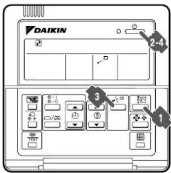
text_image
DAIKIN 2-4 3 1
text_image
DAIKIN * 217°C 21°C + - - - - - - - - - - - - - - - - - - - - - - - - - - - - - - - - - - - - - - - - - - - - - - - - - - - - - - - - - - - - - - - - - - - - - - - - - - -1-2345
text_image
Double-flow Multi-flow Corner Ceiling Suspended Wall Mounted
text_image
Double-flow Multi-flow Corner Ceiling Suspended Wall Mounted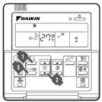
text_image
DAIKIN * 3° 217° 21°C 1 2 3
text_image
DAIKIN * 3 4 5 6 7 8 9 10 11 12 13 14 15 16 17 18 19 20 21 22 23 24 25 26 27 28 29 30 31 32 33 34 35 36 37 38 39 40 41 42 43 44 45 46 47 48 49 50 51 52 53 54 55 56 57 58 59 60 61 62 63 64 65 66 67 68 69 70 71 72 73 74 75 76 77 78 79 80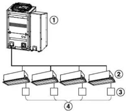
flowchart
graph TD
    A["Device ①"] --> B["Branch ②"]
    A --> C["Branch ③"]
    A --> D["Branch ④"]
    B --> E["Output"]
    C --> F["Output"]
    D --> G["Output"]
789
text_image
DAIKIN * 270° 1-2-3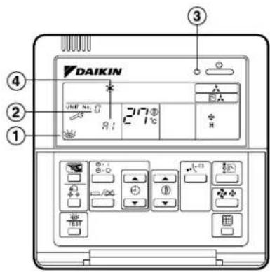
text_image
DAIKIN ① ② ③ ④ JMF No. 217 EA H ⑤10 11
CONTENTS
- SAFETY PRECAUTIONS .... 1
- SPECIFICATIONS...... 4
- WHAT TO DO BEFORE OPERATION .... 4
- REMOTE CONTROLLER: NAME AND FUNCTION OF EACH SWITCH AND DISPLAY 4
- OPERATION RANGE.... 5
- OPERATION PROCEDURE 6
- OPTIMUM OPERATION 9
- SEASONAL MAINTENANCE....9
- FOLLOWING SYMPTOMS ARE NOT AIR CONDITIONER TROUBLES.... 10
- TROUBLE SHOOTING 11
The English text is the original instruction. Other languages are translations of the original instructions.
1. SAFETY PRECAUTIONS
To gain full advantage of the air conditioner's functions and to avoid malfunction due to mishandling, please read this operation manual carefully before use.
This air conditioner is classified under “appliances not accessible to the general public”.
The precautions described herein are classified as WARNING and CAUTION. They both contain important information regarding safety. Be sure to observe all precautions without fail.

WARNING ......Failure to follow these instructions properly may result in personal injury or loss of life.

CAUTION ......Failure to observe these instructions properly may result in property damage or personal injury, which may be serious depending on the circumstances.
After reading, keep this manual in a convenient place so that you can refer to it whenever necessary. If the equipment is transferred to a new user, be sure also to hand over the manual.

WARNING
Be aware that prolonged, direct exposure to cool or warm air from the air conditioner, or to air that is too cool or too warm can be harmful to your physical condition and health.
When the air conditioner is malfunctioning (giving off a burning odour, etc.) turn off the power to the unit and contact your local dealer.
Continued operation under such circumstances may result in a failure, electric shocks or fire hazards.
Consult your local dealer about installation work. Doing the work yourself may result in water leakage, electric shocks or fire hazards.
Consult your local dealer regarding modification, repair and maintenance of the air conditioner.
Improper workmanship may result in water leakage, electric shocks or fire hazards.
Do not place objects, including rods, your fingers, etc., in the air inlet or outlet.
Injury may result due to contact with the air conditioner's highspeed fan blades.
Beware of fire in case of refrigerant leakage.
If the air conditioner is not operating correctly, i.e. not generating cool or warm air, refrigerant leakage could be the cause. Consult your dealer for assistance. The refrigerant used for the air conditioner is safe and normally does not leak.
However, if the refrigerant leaks and gets in contact with a naked burner, heater or cooker, it may generate hazardous compounds. Turn off the air conditioner and call the dealer. Make sure to turn on the air conditioner after the qualified service person confirms that the leakage is repaired.
Consult your local dealer regarding what to do in case of refrigerant leakage.
When the air conditioner is to be installed in a small room, it is necessary to take proper measures so that the amount of any leaked refrigerant does not exceed the concentration limit in the event of a leakage. Otherwise, this may lead to an accident due to oxygen depletion.
Contact professional personnel about attachment of accessories and be sure to use only accessories specified by the manufacturer.
If a defect results from your own workmanship, it may result in water leaks, electric shock or fire.
Consult your local dealer regarding relocation and reinstallation of the air conditioner.
Improper installation work may result in leakage, electric shocks or fire hazards.
Be sure to use fuses with the correct ampere reading.
Do not use improper fuses, copper or other wires as a substitute, as this may result in electric shock, fire, injury or damage to the unit.
Be sure to install an earth leakage breaker.
Failure to install an earth leakage breaker may result in electric shocks or fire.
Be sure to earth the unit.
Do not earth the unit to a utility pipe, lightning conductor or telephone earth lead. Imperfect earthing may result in electric shocks or fire.
A high surge current from lightning or other sources may cause damage to the air conditioner.
Consult the dealer if the air conditioner sub-merges owing to a natural disaster, such as a flood or typhoon.
Do not operate the air conditioner in that case, or otherwise a malfunction, electric shock, or fire may result.
Start or stop the air conditioner with the remote controller. Never use the power circuit breaker for this purpose.
Otherwise, it may cause fire or water leakage. Furthermore, if an automatic reset control is provided against power failure and the power is recovered, the fan will rotate suddenly and may cause injury.
Do not use the product in the atmosphere contaminated with oil vapor, such as cooking oil or machine oil vapor.
Oil vapor may cause crack damage, electric shocks, or fire.
Do not use the product in places with excessive oily smoke, such as cooking rooms, or in places with flammable gas, corrosive gas, or metal dust.
Using the product in such places may cause fire or product failures.
Do not use flammable materials (e.g., hair-spray or insecticide) near the product.
Do not clean the product with organic solvents such as paint thinner.
The use of organic solvents may cause crack damage to the product, electric shocks, or fire.
Be sure to use a dedicated power supply for the air conditioner.
The use of any other power supply may cause heat generation, fire, or product failures.
Consult your dealer regarding cleaning the inside of the air conditioner.
Improper cleaning may cause breakage of plastic parts, water leakage and other damage as well as electric shocks.
Do not operate the air conditioner when using a room fumigation - type insecticide.
Failure to observe could cause the chemicals to become deposited in the unit, which could endanger the health of those who are hypersensitive to chemicals.

CAUTION
Do not use the air conditioner for purposes other than those for which it is intended.
Do not use the air conditioner for cooling precision instruments, food, plants, animals or works of art as this may adversely affect the performance, quality and/or longevity of the object concerned.
Do not remove the outdoor unit's fan guard.
The guard protects against the unit's high speed fan, which may cause injury.
To avoid oxygen deficiency, ensure that the room is adequately ventilated if equipment such as a burner is used together with the air conditioner.
After prolonged use, check the unit stand and its mounts for damage.
If left in a damaged condition, the unit may fall and cause injury.
Do not place flammable sprays or operate spray containers near the unit as this may result in fire.
Do not put flammable containers, such as spray cans, within 1 m from the air outlet.
The containers may explode because the warm air output of the indoor or outdoor unit will affect them.
Before cleaning, be sure to stop unit operation, turn the power circuit breaker off or remove the power cord.
Otherwise, an electric shock and injury may result.
Do not wipe the controller operation panel with benzine, thinner, chemical dustcloth, etc.
The panel may get discolored or the coating peeled off. If it is heavily dirty, soak a cloth in water-diluted neutral detergent, squeeze it well and wipe the panel clean. And wipe it with another dry cloth.
To avoid electric shocks, do not operate with wet hands.
Do not place objects that are susceptible to moisture directly beneath the indoor or outdoor units.
Under certain conditions, condensation on the main unit or refrigerant pipes, air filter dirt or drain blockage may cause dripping, resulting in fouling or failure of the object concerned.
Do not place appliances that produce naked flames in places exposed to the air flow from the unit as this may impair combustion of the burner.
Do not place heaters directly below the unit, as resulting heat can cause deformation.
Do not allow a child to mount on the outdoor unit or avoid placing any object on it.
Falling or tumbling may result in injury.
Be sure that children, plants or animals are not exposed directly to airflow from the unit, as adverse effects may ensue.
Do not wash the air conditioner or the remote controller with water, as this may result in electric shocks or fire.
Do not place water containers (flower vases, etc.) on the unit, as this may result in electric shocks or fire.
Do not install the air conditioner at any place where there is a danger of flammable gas leakage.
In the event of a gas leakage, build-up of gas near the air conditioner may result in fire hazards.
Carry out drain piping properly to ensure complete drainage.
If drain piping is not carried out properly, drain will not flow out. Then, dirt and debris may be accumulated in the drain pipe and may cause water leakage. If it occurs, stop the air conditioner and call your dealer for assistance.
The appliance is not intended for use by unattended young children or persons who are incompetent to operate air conditioners.
It may result in injury or electric shock.
Children should be watched so that they do not play with the unit or its remote controller.
Accidental operation by a child may result in injury or electric shock.
To avoid injury, do not touch the air inlet or aluminium fins of the unit.
Do not place objects in direct proximity of the outdoor unit and do not let leaves and other debris accumulate around the unit.
Leaves are a hotbed for small animals which can enter the unit. Once in the unit, such animals can cause malfunctions, smoke or fire when making contact with electrical parts.
Do not block air inlets nor outlets.
Impaired airflow may result in insufficient performance or trouble.
Do not let children play on or around the outdoor unit.
If they touch the unit carelessly, injury may be caused.
Turn off the power when the unit is not to be used for long periods of time.
Otherwise, the unit may get hot or catch on fire due to dust accumulation.
Never touch the internal parts of the remote controller.
Do not remove the front panel. Touching certain internal parts will cause electric shocks and damage to the unit. Please consult your dealer about checking and adjustment of internal parts.
Do not leave the remote controller wherever there is a risk of wetting.
If water gets into the remote controller there is a risk of electrical leakage and damage to electronic components.
Never press the button of the remote controller with a hard, pointed object.
The remote controller may be damaged.
Watch your steps at the time of air filter cleaning or inspection.
High-place work is required, to which utmost attention must be paid.
If the scaffold is unstable, you may fall or topple down, thus causing injury.
[Place of Installation]
- Make sure that the air conditioner is located in a sufficiently ventilated place not surrounded by obstacles.
- Do not use the air conditioner in the following places.
a. Places with a mist of mineral oil, such as cutting oil.
b. Locations such as coastal areas where there is a lot of salt in the air.
c. Locations such as hot springs resorts where there is a lot of sulfur in the air.
d. Locations such as factories where the power voltage varies a lot.
e. In cars, boats, and other vehicles.
f. Locations such as kitchens where oil may splatter or there is steam in the air.
g. Locations where equipment that produces electromagnetic waves is found.
h. Places with an acid or alkaline mist.
i. Places where fallen leaves are accumulated or weeds grow close together.
• Take snow protection measures.
Contact your dealer for the details of snow protection measures, such as the use of a snow protection hood.
[Electrical Work]
- Do not attempt to conduct electrical work or grounding work unless you are licensed to do so.
Consult with your dealer for electrical work and grounding work.
- Use a dedicated circuit for the air conditioner.
[Pay Attention to Operating Sound]
- Be sure to use the following places.
a. Places that can sufficiently withstand the weight of the air conditioner and suppress the operating sound and vibration of the air conditioner.
b. Places where warm air from the air outlet of the outdoor unit or the operating sound of the outdoor unit does not annoy neighbors.
- Make sure that there are no obstacles close to the outdoor unit.
Obstacles close to the outdoor unit may drop the performance of the outdoor unit or an increase in the operating sound of the outdoor unit.
- Consult your dealer if the air conditioner in operation generates unusual noise.
[Drainage through Drainpipe]
- Make sure that the drainpipe is installed properly to drain water.
If no water is discharged from the drainpipe while the air conditioner is cooling operation, the drainpipe may be clogged with dust or dirt and water leakage from the indoor units may result.
Stop operating the air conditioner and consult your dealer.
2. SPECIFICATIONS
| Model | |||
| System name | RTSYQ10PAY1 | RTSYQ14PAY1 | |
| Indipendent unit | RTSQ10PAY1 | RTSQ14PAY1 | |
| BTSQ20PY1 | BTSQ20PY1 | ||
| Power supply | |||
| Phase | - | 3N~ | 3N~ |
| Frequency | (Hz) 50 50 | ||
| Voltage | (V) 380-415 380-415 | ||
| Nominal cooling capacity | (kW) 28.0 | 40.0 | |
| Nominal heating capacity | (kW) 31.5 | 45.0 | |
| Dimensions H×W×D | (mm) | 1680×930×765+1570×460×765 | 1680×1240×765+1570×460×765 |
| Mass | (kg) | 257+110 | 338+110 |
| Refrigerant | |||
| type | - | R410A | R410A |
| charge (*1) | (kg) | 10.5 | 11.7 |
| Design pressure | |||
| High side | (bar) | 40 40 | |
| (MPa) | 4.0 | 4.0 | |
| Low side | (bar) | 33 33 | |
| (MPa) | 3.3 | 3.3 | |
| Model | |||
| System name | RTSYQ16PAY1 | RTSYQ20PAY1 | |
| Indipendent unit | RTSQ16PAY1 | RTSQ8PAY1 | |
| BTSQ20PY1 | RTSQ12PAY1 | ||
| BTSQ20PY1 | |||
| Power supply | |||
| Phase | - | 3N~ | 3N~ |
| Frequency | (Hz) 50 50 | ||
| Voltage | (V) 380-415 380-415 | ||
| Nominal cooling capacity | (kW) 45.0 | 56 | |
| Nominal heating capacity | (kW) 50.0 | 63 | |
| Dimensions H×W×D | (mm) | 1680×1240×765+1570×460×765 | 1680×930×765+1680×930×765+1570×460×765 |
| Mass | (kg) | 344+110 | 205+257+110 |
| Refrigerant | |||
| type | - | R410A | R410A |
| charge (*1) | (kg) | 11.7 | 9.4+10.9 |
| Design pressure | |||
| High side | (bar) | 40 40 | |
| (MPa) | 4.0 | 4.0 | |
| Low side | (bar) | 33 33 | |
| (MPa) | 3.3 | 3.3 | |
*1: Refrigerant charge at factory shipment
[INFORMATION RELATED ENVIRONMENT]
This product contains fluorinated greenhouse gases covered by the Kyoto protocol.
Type of refrigerant: R410A, GWP(*) value: 1975 (*)GWP=global warming potential
Periodical inspections on refrigerant leakages may be required depending on European or local legislation.
Please contact your installer for more information.
This operation manual is for the following system with standard control. Before initiating operation, contact your Daikin dealer for the operation that corresponds to your system type and mark.
If your installation has a customized control system, ask your Daikin dealer for the operation that corresponds to your system.
Outdoor units (Refer to figure 1)
| Operation modes | |
| Inverter series | |
| Heat pumpsRTSYQseries | |
- Names and functions of parts (Refer to figure 1)
- Outdoor unit
- Indoor unit
- Remote controller
- Inlet air
- Outlet air
- Refrigerant piping
4. REMOTE CONTROLLER: NAME AND FUNCTION OF EACH SWITCH AND DISPLAY (Refer to figure 2)
- On/off button
Press the button and the system will start. Press the button again and the system will stop.
- Operation lamp (red)
The lamp lights up during operation. - Display " [ ] " (changeover under control) It is impossible to changeover heat/cool with the remote controller which display this icon. Refer to the chapter "6-5 SETTING THE MAS-TER REMOTE CONTROLLER".
- Display " √" (airflow flap)
Refer to the chapter "6-3 ADJUSTING THE AIRFLOW DIRECTION".
- Display "OPTION"
(ventilation/air cleaning
This display shows that the ventilation unit are in operation. (these are optional accessories)
- Display “ 2^17 ” (set temperature)
This display shows the temperature you have set.
- Display “ ✉” “ ☐” “ ✱” “ ⚙ ” (operation mode)
This display shows the current operation mode.
- Display “ 3_hr4_hr ” (programmed time)
This display shows the programmed time of the system start or stop.
- Display "TEST" (inspection/test operation)
When the inspection/test operation button is pressed, the display shows the mode in which the system actually is.
- Display " [★] (under centralized control)
When this display shows, the system is under centralized control. (This is not a standard specification.)
- Display " ✉ ✉" (fan speed)
This display shows the fan speed you have selected.
- Display “” (time to clean air filter)
Refer to the operation manual of indoor unit.
- Display "✿/💡" (defrost/hot start)
Refer to the "EXPLANATION OF HEATING OPERATION" in chapter 6-1.
- Timer mode start/stop button
Refer to the chapter "6-4 PROGRAMMING START AND STOP OF THE SYSTEM WITH TIMER".
- Timer on/off button
Refer to the chapter "6-4 PROGRAMMING START AND STOP OF THE SYSTEM WITH TIMER".
- Inspection/test operation button
This button is only used by qualified service persons for maintenance purposes.
- Programming time button
Use this button for setting the programming start and/or stop time.
Refer to the chapter "6-4 PROGRAMMING START AND STOP OF THE SYSTEM WITH TIMER".
- Temperature setting button
Use this button for setting the desired temperature. Refer to the chapter "6-1 COOLING, HEATING AND FAN ONLY OPERATION".
- Filter sign reset button
Refer to the operation manual of indoor unit.
- Fan speed control button
Press this button to select the fan speed of your preference.
- Operation mode selector button
- Press this button to select the operation mode of your preference.
- Press this button to designate the master remote controller.
Refer to the chapter "6-5 SETTING THE MAS-TER REMOTE CONTROLLER".
- Airflow direction adjust button
Refer to the chapter "6-3 ADJUSTING THE AIRFLOW DIRECTION".
- Thermistor
It sense the room temperature around the remote controller.
- These button are used when the ventilation unit are installed (These are optional accessories)
Refer to the operation manual of the ventilation unit.
NOTE

- Do not place the controller exposed to direct sunlight. The LCD display may get discolored, failing to display the data.
- Never pull or twist the electric wire of a remote controller.
It may cause the unit to malfunction.
- Do not allow sharp or hard items to touch the buttons of the remote controller.
The remote controller may be damaged or breakdown may occur.
- In contradistinction to actual operating situations, the display on figure 2 shows all possible indications.
• Figure 2 shows the remote controller which is opened the cover.
- For FXS, FXM, FXL and FXN, the airflow direction ajust button (22) is not available and the display (4) shows "NOT AVAILABLE" when pressed.
5. OPERATION RANGE
Use the system in the following temperature and humidity ranges for safe and effective operation.
| COOLING HEATING | |
| outdoor temperature | -5^ 43^ -25^ 15.5^ |
| indoor temperature | 14^ 25^ 15^ 27^ |
| indoor humidity | ≤ 80% —— |
NOTE

- Cooling operation:
If the air conditioner is operated continuously while the indoor temperature is 21^ C or below and the humidity is 80% or over, the interiors of the indoor units may cause icing and water leakage may result.
- Heating operation:
The air conditioner may stop operating for the protection of the machine if the outdoor temperature is 21^ C or over.
- Operation procedure varies according to the combination of outdoor unit and remote controller. Read the chapter "What to do before operation".
- To protect the unit, turn on the main power switch 6 hours before operation.
And do not turn off the power supply during the air conditioning season because of smoothly start up. - If the main power supply is turned off during operation, operation will restart automatically after the power turns back on again.
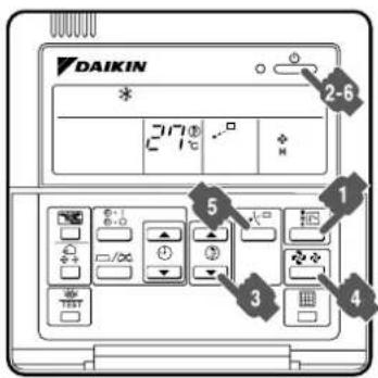
OPERATING THE SYSTEM (Refer to figure 3)

Press the operation mode selector button several times and select the operation mode of your choice;
“ * ” Cooling operation
“ ⚙ ” Heating operation
“ ✿” Fan only operation
NOTE
- The operation mode cannot be changed with the remote controller whose display shows “” (changeover under control).
Change the operation mode with the remote controller whose display does not show "☐". - When the display “ [F]” (changeover under control) flashes, refer to the chapter “6-5 SETTING THE MASTER REMOTE CONTROLLER”.

Press the on/off button.
The operation lamp lights up and the system starts operation.
ADJUSTMENT (Refer to figure 3)
For adjustment the desired temperature, fan speed and airflow direction (only for the remote controller BRC1A51: FXC, FXF, FXH, FXK, FXA), follow the procedure shown below.

Press the temperature setting button and set the desired temperature.
Each time this button is pressed, the temperature setting rises or lowers 1^ C.
NOTE
- Set the temperature within the operation range.
- The temperature setting is impossible for fan only operation.

Press the fan speed control button and select the fan speed of your preference.
NOTE
- For machine protection the system may control the airflow rate automatically.
- The airflow rate may be adjusted automatically depending on the room temperature or the fan may stop immediately. This is not a malfunction.
- It may take sometime for finishing to change the airflow rate.
This is normal operation.

Press airflow direction adjust button. Refer to the chapter "6-3 ADJUSTING THE AIRFLOW DIRECTION" for details.
STOPPING THE SYSTEM (Refer to figure 3)

Press the on/off button once again. The operation lamp goes off and the system stops operation.
NOTE
- The fan may keep on running for about 1 minute after the heating operation stops for removing the heat in the indoor unit.
- Do not turn off the power immediately after the unit stops.
The system need at least 5 minutes for residual operation of drain pump device. Turning off the power immediately will cause water leak or trouble.
- In general, heating operation may take longer to reach the set temperature than in cooling operation. We recommend starting the operation which was used before using timer operation.
- The following operation is performed in order to prevent the heating capacity from dropping or cold air from blowing.
Defrost operation
- In heating operation, freezing of the outdoor unit heat exchanger increases. Heating capability decreases and the system goes into defrost operation.
- The airflow will be set to breeze or stop.
- If stopped, the display of the remote controller shows “ [*/①]”.
- Once the airflow is set to breeze or stop, the air conditioner will return to the previous state in approximately 10 to 15 minutes.
Hot start
- In order to prevent cold air from blowing out of an indoor unit at the start of heating operation, the indoor fan is automatically stopped. The display of the remote controller shows “/☐”.
- The heating capacity drops as the outside temperature falls. If this happens, use another heating device together with the unit. (When using the appliances which produce open fire together, ventilate a room constantly.)
Do not place appliances which produce open fire in places exposed to the airflow from the unit or under the unit. - It takes some time for the room to warm up from the time the unit is started since the unit is a hot-air circulatory system to warm the entire room.
- If the hot air rises to the ceiling, leaving the area above the floor cold, we recommend using the circulator (the indoor fan for circulating air). Contact your dealer for details.
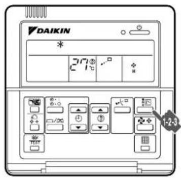
6-2 PROGRAM DRY OPERATION (Refer to figure 4)
- The program dry function deprives the room of moisture while the air conditioner is in intermittent weak cooling operation so that the room temperature will not become too low.
- The microcomputer automatically controls the temperature and fan speed, so these cannot be set using the remote controller.
- This function is not available if the room temperature is 20^ or lower.
• This function does not controls the humidity. - FXL and FXN type indoor unit can not operate program dry operation.
NOTE

- If “ ✝ ” (Cooling operation) is not displayed, refer to “6-1 COOLING, HEATING AND FAN ONLY OPERATION”, and set “ ✝ ” (Cooling operation). Unless the air conditioner is set to “ ✝ ” (Cooling operation), the air conditioner cannot be switched over to “ ☐ ” (program dry operation).
Press the operation mode selector button several times and select “ 🔍 ” (program dry operation).
2 Press the on/off button.
The operation lamp lights up and the system starts operation.
Press the airflow direction adjust button (only for FXC, FXF, FXH, FXK, FXA). Refer to the chapter "6-3 ADJUSTING THE AIRFLOW DIRECTION" for details.
4 Press the on/off button once again.
The operation lamp goes off and the system stops operation.
NOTE

- Do not turn off the power immediately after the unit stops. The system need at least 5 minutes for residual operation of drain pump device. Turning off the power immediately will cause water leak or trouble.
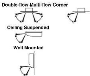
6-3 ADJUSTING THE AIRFLOW DIRECTION (Refer to figure 5) (only for Double-flow, Multi-flow, Corner, Ceiling-suspended and Wall-mounted)
Press the airflow direction adjust button to select the air direction.
The airflow flap display swings as shown right and the airflow direction continuously varies. (Automatic swing setting)

2 Press the airflow direction adjust button to select the air direction of your choice.
The airflow flap display stops swinging and the airflow direction is fixed. (Fixed airflow direction setting)

MOVEMENT OF THE AIRFLOW FLAP
For the following conditions, a micro computer controls the airflow direction which may be different from the display.
| COOLING HEATING | |
| ____ | When starting operation.When the room temperature is higher than the set temperature.At defrost operation. |
| When operating continuously at horizontal airflow direction.When continuous operation with downward airflow is performed at the time of cooling with a ceiling-suspended or a wall-mounted unit, the microcomputer may control the flow direction, and then the remote control indication also will change. | |
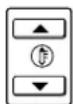
The airflow direction can be adjusted in one of the following ways.
Automatic “”. The airflow direction will very continuously. (Refer to figure 6-1)
Desired position “ ” The airflow direction can be fixed by the user.
(Refer to figure 6-2)
NOTE

- The movable limit of the flap is changeable. Contact your Daikin dealer for details. (Only for Double-flow, Multi-flow, Corner, Ceiling-suspended and Wall-mounted.)
- Avoid operating in the horizontal direction “_☐”. It may cause dew or dust to settle on the ceiling.
6-4 PROGRAMMING START AND STOP OF THE SYSTEM WITH TIMER (Refer to figure 7)
- The timer is operated in the following two ways.
Programming the stop time “ ”▶ ○
The system stops operating after the set time has elapsed.
Programming the start time “ ”▶ I
The system starts operating after the set time has elapsed.
- The timer can be programmed for a maximum of 72 hours.
- The start and the stop time can be simultaneously programmed.
Press the timer mode start/stop button several times and select the mode on the display. The display flashes.
- For setting the timer stop “ ⏻▶○”
- For setting the timer start “ ⏻ ▶ I”
2 Press the programming time button and set the time for stopping or starting the system.
Each time this button is pressed, the time advances or goes backward by 1 hour.
Press the timer on/off button. The timer setting procedure ends. The display “◀▶○” or “◀▶|” changes from flashing light to constant light.
NOTE

- When setting the timer off and on at the same time, repeat the above procedure (from “1” to “3”) once again.
• After the timer is programmed, the display shows the remaining time.
- Press the timer on/off button once again to cancel programming. The display vanishes.
For example: (Refer to figure 8)
When the timer is programmed to stop the system after 3 hours and start the system after 4 hours, the system will stop after 3 hours and start 1 hour later.
6-5 SETTING THE MASTER REMOTE CONTROLLER
- In the case of the system as shown in figure 9, only the master remote controller can select operation mode.
(Refer to figure 9)
-
Outdoor unit
-
Indoor unit
-
Remote controller
-
One of these remote controller is master remote controller.
- Only the master remote controller can select heating, cooling operation.
- The displays of slave remote controllers show "changeover under control) and they automatically follow the operation mode directed by the master remote controller.
However, it is possible to changeover to program dry with slave remote controllers if the system is in cooling operation by setting on the master remote controller and to changeover to fan only operation.
How to designate the master remote controller (Refer to figure 10)
Press the operation mode selector button of the current master remote controller for 4 seconds.
The display showing "☐" (changeover under control) of all remote controllers connected to the same outdoor unit flashes.
2 Press the operation mode selector button of the controller that you wish to designate as the master remote controller. Then designation is completed. This remote controller is designated as the master remote controller and the display showing " [ ] " (changeover under control) vanishes.
The displays of other remote controllers show " [ ] (changeover under control).
How to change the operation mode (Refer to figure 10)
Press the operation mode selection button of the master remote controller, which does not show “” (changeover under control) repeatedly until the air conditioner is set to the desired operation mode.
The display will change to “” or “” each time the button is pressed.
The other remote controllers with no option rights will follow suit and change their displays automatically.
6-6 PRECAUTIONS FOR GROUP CONTROL SYSTEM OR TWO REMOTE CONTROLLER CONTROL SYSTEM
This system provides two other control systems beside individual control (one remote controller controls one indoor unit) system. Confirm about your system to Daikin dealer.
• Group control system
One remote controller controls up to 16 indoor units. All indoor units are equally set.
- Two remote controller control system
Two remote controllers control one indoor unit (in case of group control system, one group of indoor units). The unit is individually operated.
NOTE
- Contact your Daikin dealer in case of changing the combination or setting of group control and two remote controller control systems.
Observe the following precautions to ensure the system operates properly.
- Prevent direct sunlight from entering a room during cooling operation by using curtains or blinds.
- Do not keep doors and windows opened. If the doors and windows remain open, air will flow out of your room causing a decrease in the cooling or heating effect.
- Do not use other heating devices directly beneath the indoor unit. If you do, they might get deformed by the heat.
- Never place objects near the air inlet or the air outlet of the unit. It may cause deterioration in the effect or stop the operation.
- Adjust the room temperature properly for a comfortable environment. Avoid excessive heating or cooling.
- Ventilate often. Extended use requires special attention to ventilation.
- When the display shows “ ” (time to clean the air filter), ask a qualified service person to clean the filters. (Refer to the chapter “Maintenance” in the indoor unit manual.)
- Keep the indoor unit and remote control at least 1 m away from televisions, radios, stereos, and other similar equipment.
Failing to do so may cause static or distorted pictures.
- Turn off the main power supply switch to the unit when the unit is not used for longer periods of time. If the switch is on, it uses electricity. Before restarting the unit, turn on the main power supply switch 6 hours before operation to ensure smooth running. (Refer to the chapter “Maintenance” in the indoor unit manual.)
- Fully use the function of airflow direction adjust. Cold air gathers on the floor, and warm air gathers in the ceiling.
Set the airflow direction parallel during cooling or dry operation, and set it downwards during heating operation.
Do not let the air blow directly to a person.
- It takes time for the room temperature to reach the set temperature.
We recommend starting the operation in advance using timer operation.
8. SEASONAL MAINTENANCE
— ⚠️ CAUTION
- Do not touch the air inlets or aluminum fins of the outdoor or indoor units.
Touching them may result in injury. - Do not wash the outdoor or indoor units with water. An electric shock or fire may result.
- Watch your steps at the time of air filter cleaning etc. If the scaffold is unstable, you may fall or topple down, thus causing injury.
- Be sure to stop the operation, and turn the breaker off before cleaning.
This may cause electric shock and injury. - Consult with the dealer for cleaning the interior of the indoor units.
Incorrect cleaning may damage the plastic parts and cause failures, such as water leakage, and an electric shock may result.
8-1 AT THE BEGINNING OF THE SEASON
Check
- Are the indoor and outdoor unit intake and outlet vents blocked?
Remove anything that might be blocking them.
Clean the exterior.
- See the operation manual included with the indoor unit for details on how to clean it.
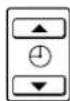
Turn the power on.
- When the power comes on, the characters in the remote controller display appear.
(To protect the unit, turn the power on at least 6 hours before operating it. This makes operation smoother.)
8-2 AT THE END OF THE SEASON
On a clear day, use fan operation for around half a day to thoroughly dry out the interior of the unit.
- Refer to chapter 6 for details on fan operation.
Turn off the power.
- When the power is shut off, the characters in the remote controller display disappear.
- When the power is on, the unit consumes up to several dozen Watts of power.
Turn off the power to conserve energy.
Clean the exterior.
- See the operation manual included with the indoor unit for details on how to clean it.
9. FOLLOWING SYMPTOMS ARE NOT AIR CONDITIONER TROUBLES
- The air conditioner does not start immediately when restart the operation after stop the operation or change operation mode after set the operation mode.
If the operation lamp lights, the system is in normal condition.
To prevent overloading of the compressor motor, the air conditioner starts 5 minutes after it is turned ON again in case it was turned OFF just before.
- If “Centralized Control” is displayed on the remote controller and pressing the operation button causes the display to blink for a few seconds.
This indicates that the central device is controlling the unit.
The blinking display indicates that the remote control cannot be used.
- The system does not start immediately after the power supply is turned on.
Wait one minute until the micro computer is prepared for operation.
9-2 IT STOPS SOMETIMES
- The remote controller display reads “U4” or “U5” and stops but then restarts after a few minutes. This is because the remote control is intercepting noise from electrical appliances other than the air conditioner, and this prevents communication between the units, causing them to stop.
Operation automatically restarts when the noise goes away.
9-3 COOL/HEAT CANNOT BE CHANGED OVER
- When the display shows “ (changeover under control).”
It shows that this is a slave remote controller. Refer to "Setting the master remote controller".
- When the cool/heat selector switch is installed and the display shows " (changeover under control).
This is because cool/heat changeover is controlled by the cool/heat selector. Ask your Daikin dealer where the remote control switch is installed.
9-4 FAN OPERATION IS POSSIBLE, BUT COOLING AND HEATING DO NOT WORK
- Immediately after the power is turned on. The micro computer is getting ready to operate. Wait 10 minutes.
9-5 THE FAN STRENGTH DOES NOT CORRESPOND TO THE SETTING
- The fan strength does no change even if the fan strength adjustment button in pressed.
During heating operation, when the room temperature reaches the set temperature, the outdoor unit goes off and the indoor unit changes to whisper fan strength.
This is to prevent cold air blowing directly on occupants of the room.
The fan strength will not change even if the button is changed, when another indoor unit is in heating operation.
9-6 THE FAN DIRECTION DOES NOT CORRESPOND TO THE SETTING
- The fan direction does not correspond to the remote control display.
The fan direction does not swing.
This is because the unit is being controlled by the micro computer. Refer to “Adjusting the airflow direction”.
9-7 WHITE MIST COMES OUT OF A UNIT Indoor unit
- When humidity is high during cooling operation. If the interior of an indoor unit is extremely contaminated, the temperature distribution inside a room becomes uneven. It is necessary to clean the interior of the indoor unit. Ask your Daikin dealer for details on cleaning the unit. This operation requires a qualified service person.
- Immediately after the cooling operation stops and if the room temperature and humidity are low.
This is because warm refrigerant gas flows back into the indoor unit and generates steam.
Outdoor unit
- When the system is changed over to heating operation after defrost operation.
Moisture generated by defrost becomes steam and is exhausted.
9-8 NOISE OF AIR CONDITIONERS
Indoor unit
- A whining sound is heard immediately after the power supply is turned on.
The electronic expansion valve inside an indoor unit starts working and makes the noise. Its volume will reduce in about one minute.
- A continuous low whir is heard when the system is in cooling operation or at a stop.
When the drain pump (optional accessories) is in operation, this noise is heard.
- A squeaking sound is heard when the system stops after heating operation.
Expansion and contraction of plastic parts caused by temperature change make this noise.
- A low murmur or trickling sound is heard while the indoor unit is stopped.
When the other indoor unit is in operation, this noise is heard. In order to prevent oil and refrigerant from remaining in the system, a small amount of refrigerant is kept flowing.
Outdoor unit
- When the tone of operating noise changes.
This noise is caused by the change of frequency.
Indoor unit, outdoor unit
- A continuous low hissing sound is heard when the system is in cooling or defrost operation.
This is the sound of refrigerant gas flowing through both indoor and outdoor units.
- A hissing sound which is heard at the start or immediately after stopping operation or defrost operation.
This is the noise of refrigerant caused by flow stop or flow change.
9-9 DUST COMES OUT OF THE UNIT
- When the unit is used after stopping for a long time.
This is because dust has gotten into the unit.
9-10 THE UNITS CAN GIVE OFF ODOURS
- During operation.
The unit can absorb the smell of rooms, furniture, cigarettes, etc., and then emit it again.
9-11 THE OUTDOOR UNIT FAN DOES NOT SPIN
- During operation.
The speed of the fan is controlled in order to optimize product operation.
9-12 THE DISPLAY SHOWS "88"
- This is the case immediately after the main power supply switch is turned on.
This means that the remote controller is in normal condition. This continues for one minute.
9-13 THE COMPRESSOR OR FAN IN THE OUTDOOR UNIT DOES NOT STOP
- This is to prevent oil and refrigerant from remaining in the compressor. The unit will stop after 5 to 10 minutes.
9-14 THE INSIDE OF AN OUTDOOR UNIT IS WARM EVEN WHEN THE UNIT HAS STOPPED
- This is because the crankcase heater is warming the compressor so that the compressor can start smoothly.
9-15 HOT AIR IS EMITTED EVEN THOUGH THE UNIT IS STOPPED
- Hot air can be felt when the unit is stopped.
Several different indoor units are being run on the same system, so if another unit is running, some refrigerant will still flow through the unit.
9-16 DOES NOT COOL VERY WELL
- Program dry operation.
Program dry operation is designed to lower the room temperature as little as possible.
Refer to page 7.
10. TROUBLE SHOOTING
If one of the following malfunctions occur, take the measures shown below and contact your Daikin dealer.
- ⚠ WARNING
Stop operation and shut off the power if anything unusual occurs (burning smells, etc.)
Leaving the unit running under such circumstances may cause breakage, electrical shock, or fire.
Contact your dealer.
- If a safety device such as a fuse, a breaker or an earth leakage breaker frequently actuates; Measure : Do not turn on the main power switch.
- If the ON/OFF switch does not properly work; Measure: Turn off the main power switch.
- If water leaks from unit; Measure: Stop the operation.
- The operation switch does not work well. Turn off the power.
- If the display “TEST”, the unit number and the operation lamp flash and the malfunction code appears; (Refer to figure 11)
-
Inspection display
-
Indoor unit number in which a malfunction occurs
-
Operation lamp
-
Malfunction code
Measure: Notify your Daikin dealer and report the malfunction code.
If the system does not properly operate except for the above mentioned cases and none of the above mentioned malfunctions is evident, investigate the system according to the following procedures.
If it is impossible to fix the problem yourself after checking all the above items, contact your dealer.
Let him know the symptoms, system name, and model name (listed on the warranty card).
- If the system does not operate at all;
- Check if there is no power failure.
Wait until power is restored. If power failure occurs during operation, the system automatically restarts immediately after the power supply is recovered.
- Check if no fuse has blown; Turn off the power supply
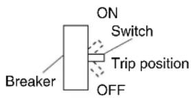
- Check if the breaker is blown.
Turn the power on with the breaker switch in the off position.
Do not turn the power on with the breaker switch in the trip position.
(Contact your dealer.)
text_image
ON Switch Breaker Trip position OFF-
If the system stops soon after starting the operation;
-
Check if air inlet or outlet of outdoor or indoor unit is not blocked by obstacles. Remove any obstacle and make it well-ventilated.
- Check if the remote controller display shows “” (time to clean the air filter);
Refer to the operation manual of the indoor unit. And clean the air filter.
-
The system operates but cooling or heating is insufficient;
-
Check if air inlet or outlet of outdoor or indoor unit is not blocked by obstacles. Remove any obstacle and make it well-ventilated.
- Check if the remote controller display shows “☐” (time to clean the air filter);
Refer to the operation manual of the indoor unit. And clean the air filter.
- Check the temperature setting.
Refer to "Operation procedure". - Check the fan speed setting on your remote controller. Refer to "Operation procedure".
- Check for open doors or windows. Shut doors and windows to prevent wind from coming in.
- Check if there are too many occupants in the room during cooling operation.
-
Check if the heat source of the room is excessive during cooling operation.
-
Check if direct sunlight enters the room during cooling operation. Use curtains or blinds.
- Check if the airflow angle is not proper. Refer to "Operation procedure".
After-sales service and warranty
After-sales service:
WARNING
- Do not modify, disassemble or repair the unit. This may cause electric shock or fire. Contact your dealer.
- If the refrigerant leaks, keep out of fire. Although the refrigerant does not usually leak, if the refrigerant leaks out into a room and comes in contact with the combustible air in the equipment such as fan heater, stove, oil (gas) cooker, etc., it will cause toxic gas to be generated. When a refrigerant leakage failure has been repaired, confirm a service person that the leakage point has been corrected surely before restarting operation.
- Do not remove or reinstall the unit by yourself. Incorrect installation may cause electrical shock or fire. Contact your dealer.
- When asking your dealer to repair, inform related staff of the details as follows:
- Product No. of air conditioner: Refer to the warranty card.
- Shipping date and installation date: Refer to the warranty card.
- Malfunction: Inform the staff of the defective details. (Malfunction code being displayed on the remote controller.)
- Name, address, telephone number
- Repair where the warranty term is expired
Contact your dealer. If necessary to repair, pay service is available.
• Minimum storage period of important parts
Even after a certain type of air conditioner is discontinued, we have the related important parts in stock for 9 years at least.
The important parts indicate parts essential to operate the air conditioner.
- Recommendations for maintenance and inspection
Since dust collects after using the unit for several years, the performance will be deteriorated to some extent.
Taking apart and cleaning inside require technical expertise, so we recommend entering a maintenance and inspection contract (at a cost) separate from normal maintenance.
- Recommended inspection and maintenance cycles
[Note: The maintenance cycle is not the same as the warranty period.]
Table 1 assumes the following usage conditions.
- Normal use without frequent starting and stopping of the machine.
(Although it varies with the model, we recommend not starting and stopping the machine more than 6 times/hour for normal use.) -
Operation of the product is assumed to be 10 hours/day, 2500 hours/year.
-
Table 1 "Inspection Cycle" and "Maintenance Cycle" Lists
| Name of Main Part | Inspection Cycle | Maintenance Cycle [replacements and/or repairs] |
| Compressor | 1 year | 20,000 hours |
| Electric motor (fan, damper, etc.) | 20,000 hours | |
| PC boards 25,000 hours | ||
| Heat exchanger 5 years | ||
| Sensor (thermistor, etc.) 5 years | ||
| Remote controller and switches | 25,000 hours | |
| Drain pan 8 years | ||
| Expansion valve 20,000 hours | ||
| Electromagnetic valve 20,000 hours | ||
| FAN | Outdoor: 10 years Indoor: 13 years |
Note 1
This table indicates main parts.
See the maintenance and inspection contract for details.
Note 2
This maintenance cycle indicates recommended lengths of time until the need arises for maintenance work, in order to ensure the product is operational as long as possible.
Use for appropriate maintenance design (budgeting maintenance and inspection fees, etc.)
Depending on the content of the maintenance and inspection contract, the inspection and maintenance cycles may in reality be shorter than those listed here.
Note 3
It is necessary to shorten the maintenance cycle and replacement cycle under tough operating conditions (e.g., the air conditioner is operated for long hours or started and stopped highly frequently) or under tough environmental conditions (e.g., the air conditioner is operated at high ambient temperatures in a highly humid place).
■Recommended replacement cycle of wear-out parts
[The cycle is not the same as the warranty period.]
- Table 2 "Replacement Cycle" Lists
| Name of Main Part | Inspection Cycle | Replacement Cycle |
| Air filter | 1 year | 5 years |
| High efficiency filter (Optional accessory) | 1 year | |
| Fuse | 10 years | |
| Crankcase heater | 8 years |
Note 1
This table indicates main parts.
See the maintenance and inspection contract for details.
Note 2
This maintenance cycle indicates recommended lengths of time until the need arises for maintenance work, in order to ensure the product is operational as long as possible.
Use for appropriate maintenance design (budgeting maintenance and inspection fees, etc.).
Contact your dealer for details.
Note: Breakage due to taking apart or cleaning inside by anyone other than our authorized dealers may not be included in the warranty.
■Moving and discarding the unit
- Contact your dealer for removing and reinstalling the system air conditioner since they require technical expertise.
- The system air conditioner uses fluorocarbon refrigerant.
Contact your dealer for discarding the system air conditioner since it is required by law to collect, transport and discard the refrigerant in accordance with relevant local and national regulations.
■Where to call
For after-sales service, etc., consult with your dealer.
■Warranty period:
- This product includes a warranty card. The warranty card is given to a customer after dealer staff fills out necessary items in the card. The customer should check the entered items and store it carefully.
Warranty period: Within one year after installation.
For further details, refer to the warranty card.
- If it is necessary to repair the air conditioner within the warranty period, contact your dealer and show your warranty card. If the warranty card is not shown, pay-service repair may be performed even though the warranty period is not expired.
DAIKIN INDUSTRIES, LTD.
Head office:
Umeda Center Bldg., 2-4-12, Nakazaki-Nishi,
Kita-ku, Osaka, 530-8323 Japan
Tokyo office:
JR Shinagawa East Bldg., 2-18-1, Konan,
Minato-ku, Tokyo, 108-0075 Japan