CM 5 - Measurement PCE Instruments - Free user manual and instructions
Find the device manual for free CM 5 PCE Instruments in PDF.

User questions about CM 5 PCE Instruments
0 question about this device. Answer the ones you know or ask your own.
Ask a new question about this device
Download the instructions for your Measurement in PDF format for free! Find your manual CM 5 - PCE Instruments and take your electronic device back in hand. On this page are published all the documents necessary for the use of your device. CM 5 by PCE Instruments.
USER MANUAL CM 5 PCE Instruments
Southpoint Business Park
Ensign way
Hampshire / Southampton
United Kingdom, SO31 4RF
From outside UK: +44
Tel: (0) 2380 98703 0
Fax: (0) 2380 98703 9
info@pce-instruments.co.uk
www.pce-instruments.com/english
www.pce-instruments.com

natural_image
Digital multimeter with dual orange and black probes connected to a red and black terminal (no visible text or symbols)Clamp Meter User's Manual
PCE-CM 5
CE
Table of Contents
LIMITED WARRANTY AND
LIMITATION OF LIABILITY .... 1
Safety Information 1
INTRODUCTION.... 3
Components and Buttons....5
Names of the Components ....5
Switches and Buttons 6
Display 6
USING THE METER 7
Display Hold....7
Manual Mode 7
Switching Between Functions 7
Backlight and worklight 8
Auto Power Off 8
Measurement Preparation 8
AC Current....9
DC Micro Amp Current ( A) 9
Table of Contents
AC/DC Voltage 10
Resistance....11
Continuity 11
Capacitance 12
Diodes....12
Frequency and Duty Cycle 13
Non-Contact Voltage (NCV) 15
Temperature (Type-K Thermocouple) 15
SPECIFICATIONS...... 16
General Specifications 16
Technical Specifications 17
MAINTENANCE....22
General Maintenance 22
Battery Replacement....22
Test Leads Replacement 23
Out of the Box 23
LIMITED WARRANTY AND LIMITATION OF LIABILITY
This instrument from PCE Instruments will be free from defects in workmanship and material for one year from the date of original purchase. This warranty does not cover defects resulting from damage caused by the user such as drops, neglect, misuse, unauthorized alteration, usage outside of specified conditions, contamination, or improper repair/maintenance. To receive service on the instrument if it becomes necessary during the warranty period, contact PCE Instruments.
A sales complaint form must be completed before returning any instrument to PCE Instruments; no service will be provided without a completed sales complaint form. The user is responsible for properly packing the unit and charges such as shipping, freight and insurance charges. The extent of PCE Instruments' liability is limited solely to the repair/replacement of the instrument. The above warranty in its entirety is inclusive and no other warranties, written or oral, are expressed or implied.
Safety Information
WARNING:
1, TO REDUCE THE RISK OF FIRE, ELECTRICAL SHOCK, DAMAGE TO THE INSTRUMENT OR PERSONAL INJURY, PLEASE FOLLOW THE SAFETY INSTRUCTIONS DESCRIBED IN THE USER MANUAL.
2, TO ENSURE SAFE OPERATION AND LIFE OF THE METER, DO NOT PLACE THE METER IN ANY ENVIRONMENT WITH HIGH PRESSURE, HIGH TEMPERATURE, DUST, EXPLOSIVE GAS OR VAPOR.
Safety Symbols
 | Note-Important safety information, refer to the instruction manual. |
 | Application around and removal from UNINSULATED HAZARDOUS LIVE conductors is permitted. |
 | Caution when testing on live conductors. |
 | Equipment protected throughout by double insulation or reinforced insulation. |
[37BW] | Conforms to UL STD. 61010-1, 61010-2-032, 61010-2-033; Certified to CSA STD C22.2 NO. 61010-1, 61010-2-032, 61010-2-033 |
 | Complies with European (EU) safety standards |
 | Earth (ground) TERMINAL |
 | Direct current |
| Alternating current |
CAT III:
Applicable to test and measuring circuits connected to the distribution part of the building's low-voltage MAINS installation. Example: fixed equipment switchboards, circuit breakers, wiring, including cables, bus bars, junction boxes, switches, sockets, output terminals on devices for industrial use and other equipment.
Warning Symbols
WARNING:
Risk of danger, important safety information. See User's manual.
CAUTION:
Statement identifies conditions and actions that a failure to follow the instructions could result in false readings, damage the meter or the equipment under test.
WARNING
Special attention should be paid when using the meter because the improper usage may cause electric shock and damage the meter. The safety measures in common safety regulations and operating instruction should be complied with when using. In order to make fully use of its functions and ensure safe operations please comply with the usage in this section carefully.
Introduction
Overview
The PCE-CM 5 is a portable, hand-held professional meter that measures AC/DC voltage, AC/DC current, resistance, capacitance, diodes, continuity, frequency, duty cycle, temperature and non-contact voltage. This meter is easy to use with one hand, suitable for professional users or amateurs, and ideal for school or home use.
Precautions:
Users must follow standard safety instructions while using the meter:
-
Once the meter is out of the package, check for any damage to the meter before using.
-
Double check the meter to make sure all the components are in good condition.
- Check the test leads before operation. Check the test leads for damage to the insulation or wires before use.
- Use the original test leads included in the package for best performance and safety. If necessary, use compatible leads with same specifications as the originals.
- Make sure to set the meter to the correct functions and measuring range before taking measurement.
- Do not use the meter on a circuit where the measuring range is over the capable range specified in the user's manual.
- Do not touch the tips of the test leads when performing measurement.
- If the measurement is above 60V DC or 30V AC, make sure to keep fingers behind the barrier and finger guards.
- Do not use the meter on a circuit if the voltage is above 600V.
- In manual mode, if the value to be measured is unknown, start the meter in the maximum range and then adjust accordingly.
- Remove the leads from the circuit first before switching between functions.
- Disconnect power and discharge all capacitors before measuring resistance, capacitance, continuity or diodes.
- Do not measure capacitance before the capacitors are discharged.
- Do not operate the meter near explosive gas, vapor or dust.
- Stop using the meter if the meter or test leads appear damaged or do not function properly.
- Do not use the meter unless the battery case is securely fastened to the back of the meter.
- Do not expose the meter to direct sunlight, heat, or moisture.
Components and Buttons Names of the Components

text_image
1.C 2.W 3.R 4.Ft 5.H 6.R 7.Ft D 8.N 9.LC 10.R 11.C 1 2 3 4 5 6 7 8 9 10 LOz μA V Hz FUNC / RAN Temp NCV 0000 COM μA Temp ±0V CAT IIa05
-
Current Jaws
-
Worklight (back side)
3.Rotary Switch
4.Function Switch
-
Hold/Backlight Button
-
Range Button
-
Frequency/ Duty Cycle Button
8.NCV Button
9.LCD Display
10.Input Jack
11.COM Jack
Switches and Buttons
FUNC button: to switch between functions
RAN button: to switch to manual range
H / ● button: to hold the reading or to turn on backlight
Hz% button: to switch between frequency and duty cycle.
NCV button: to activate non-contact voltage detection
Rotary Switch: switch between measurement modes
INPUT: Input jack for measuring AC/DC voltage, DC current, resistance, capacitance, diodes, continuity, frequency, duty cycle and temperature.
COM: Common input jack
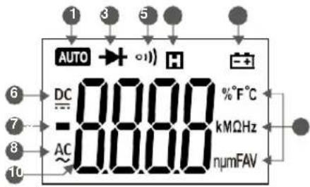
Display
text_image
1 3 5 AUTO DC -0.000 AC 0.000 H - %°F°C kMΩHz numFAV- Auto range mode 6. Direct current
- Diode mode 7. Polarity indicator
- Continuity mode 8. Alternating current
- Hold display 9. Measurement units
- Low battery 10. Measurement display
06
Using the Meter
Display Hold
During measurement, press / to hold the current reading on the display. Press again to release the hold.
Manual Mode
- The default range in voltage and resistance modes is auto. To switch to manual range, press "RAN" and the display switches to manual mode. Each press of the button increases the range and returns to the lowest range when pressed in the highest range.
- Hold "RAN" to switch back to auto-range.
Note:
In current mode, manual is only mode available. In frequency and capacitance modes, only auto-range is available.
Switching Between Functions
- When the meter is in voltage mode, press "FUNC" to switch between DC and AC voltage.
- When the meter is in resistance/continuity/capacitance/diode mode, press "FUNC" to switch between them.
- When the meter is in temperature mode, press "FUNC" to switch between Fahrenheit and Celsius units.
Backlight and worklight
- Hold / to turn on the display backlight; the backlight will stay on for 15 seconds before it automatically turns off.
• To turn off the backlight manually, hold / again. - When the meter is in current mode, turning on the backlight will also activate the worklight, making it easier to use the clamp in dark areas.
Note:
- The meter uses an LED for a backlight; even though the backlight is set to turn off after 15 seconds, use only when necessary to conserve battery life.
Auto Power Off
- If the meter is not used for 15 minutes, the meter will turn it self off to conserve battery life.
- To turn the meter back on after auto off, press "FUNC".
- To disable auto power off, hold "FUNC" while turning the meter on.
Measurement Preparation
- Make sure that when measuring current, the current being measured does not exceed the maximum rated current. This can cause overheating and damage the meter.
- When measuring in manual range and the value to be measured is unknown, start in the highest range and adjust the range as needed.
- Make sure to turn the rotary switch to the proper position before connecting the leads to a circuit.
- When connecting to a circuit, connect the black lead (COM jack) first before connecting the red lead (INPUT jack). Remove the leads in the opposite order when finished.
AC Current
WARNING:
TO AVOID ELECTRICAL SHOCK AND INJURY, PLEASE REMOVE TEST LEADS BEFORE MAKING CURRENT MEASUREMENTS.
- Turn the rotary switch to the current position. 2. Insert the conductor to be measured inside the fork. 3. Read the measured current value on the display.
Note:
- Measuring two or more conductors will cancel out readings. Only measure one conductor at atime.
- For best results, keep the conductor in the middle of the clamp.
- “⚠”indicates the maximum input AC Current is 200A AC RMS.
DC Micro Amp Current ( A)
- Insert the black test lead into "COM" jack and red test lead into "INPUT" jack.
- Turn the rotary switch to the A position.
- Connect the test leads in series to the circuit to be tested.
- Read the measured current value on the display.
Note:
- “⚠️”indicates the maximum input DC Current is 1000μA DC.
AC/DC Voltage
WARNING:
USE CAUTION WHEN MEASUREING HIGH VOLTAGE CIRCUITS TO AVOID ELECTRICAL SHOCK AND INJURY. DO NOT MEASURE INPUT VOLTAGES HIGHER THEN 600V AC/DC.
- Insert the black test lead into "COM" jack and red test lead into "INPUT" jack.
- Turn the rotary switch to the V ≈ The default mode is DC voltage; press “FUNC” to switch to AC voltage if necessary; press “FUNC” to switch back to DC voltage.
- Connect the test leads across the voltage source or load.
- Read the measured voltage value on the display.
Note:
- When measuring small voltage sources, the display will show unsteady readings until the leads are connected to the circuit. This is normal due to the high sensitivity of the meter. The meter will display the correct reading once the leads are connected to the circuit.
- “⚠️” indicates the maximum input voltage is 1000V DC/750V AC.
Resistance
WARNING:
TO AVOID ELECTRICAL SHOCK AND INJURY, TURN OFF POWER TO THE CIRCUIT AND DISCHARGE ALL CAPACITORS BEFORE MEASURING RESISTANCE.
- Insert the black test lead into "COM" jack and red test lead into "INPUT" jack.
- Turn the rotary switch to the position.
- Connect the test leads across the circuit to be tested.
4.Read the measured resistance value on the display.
Note:
- If the resistance is too high or the test leads are disconnected, the display shows "OL".
- The meter may take several seconds to get a steady reading if the resistance being measured is more than 1M . This is normal for high resistance circuits.
Continuity
WARNING:
TO AVOID ELECTRICAL SHOCK AND INJURY, TURN OFF POWER TO THE CIRCUIT AND DISCHARGE ALL CAPACITORS BEFORE MEASURING CONTINUITY.
- Insert the black test lead into "COM" jack and red test lead into "INPUT" jack.
- Turn the rotary switch to the position. Press "FUNC" to switch to continuity mode.
- Connect the test leads across the circuit to be tested.
4.Read the measured resistance value on the display. - If the resistance is less than 50 , the meter's buzzer will sound.
Note:
If the resistance is higher than 60MΩ or the leads are disconnected, the display shows "OL".
Capacitance
WARNING:
TO AVOID ELECTRICAL SHOCK AND INJURY, TURN OFF POWER TO THE CIRCUIT AND DISCHARGE ALL CAPACITORS BEFORE MEASURING CAPACITANCE.
- Insert the black test lead into "COM" jack and red test lead into "INPUT" jack.
- Turn the rotary switch to the =0 position. Press "FUNC" twice to switch to capacitance mode.
- Connect the test leads across the circuit to be tested.
- Read the measured resistance value on the display.
- For better accuracy on measurements below 10nF, touch the tips of the leads together before measurement and subtract the distributed capacitance of the meter from the actual measurement.
- For measurements on large capacitances, allow up to 30 seconds for the reading to stabilize.
Note:
Diodes
- Insert the black test lead into "COM" jack and red test lead into "INPUT" jack.
- Turn the rotary switch to the position. Press "FUNC" three times to switch to diode mode.
- Connect the red lead to the anode (+) and the black lead to the cathode (-).
- Read the measured forward biased voltage drop on the display.
Note:
- If the leads are connected backwards or to an open circuit, the display will show "OL".
Frequency and Duty Cycle
In Current Mode (A)
WARNING:
REMOVE THE TEST LEADS FROM THE METER WHEN PERFORMING A CURRENT MEASUREMENT WITH THE FORK TO AVOID ELECTRICAL SHOCK AND INJURY.
- Turn the rotary switch to the current position. 2. Insert the conductor to be measured inside the fork. 3. Press "Hz/%" button to measure frequency.
- Press "Hz/%" again to measure duty if necessary.
- Read the measured frequency or duty cycle value on the display.
Note:
- Measuring two or more conductors will cancel out readings. Only measure one conductor at a time.
- “⚠”indicates the maximum input current is 200AAC RMS.
- Frequency range is 10Hz\~1kHz. When the frequency being measured is less than 10Hz or if the frequency is higher than 1kHz, the accuracy is not guaranteed.
In Voltage Mode (V)
WARNING:
DO NOT MEASURE VOLTAGES OF MORE THAN 600V AC TO AVOID ELECTRICAL SHOCK AND INJURY.
- Insert the black test lead into "COM" jack and red test lead into "INPUT" jack.
- Turn the rotary switch to the V ≈ position. Press “FUNC” to switch to AC voltage.
- Press "Hz/%" button to measure frequency.
- Press "Hz/%" again to measure duty if necessary.
- Connect the test leads across the voltage source or load.
- Read the measured frequency or duty cycle value on the display.
Note:
- “⚠”indicates the maximum input current is 600A AC RMS.
- Frequency range is 10Hz\~10kHz. When the frequency being measured is less than 10Hz or if the frequency is higher than 10kHz, the accuracy is not guaranteed.
In Hertz Mode (Hz)
WARNING:
DO NOT MEASURE INPUTS OF MORE THAN 250V AC TO AVOID ELECTRICAL SHOCK AND INJURY.
- Insert the black test lead into "COM" jack and red test lead into "INPUT" jack.
- Turn the rotary switch to the Hz position. The default mode is frequency; press "Hz%" to switch to duty cycle if necessary.
- Connect the test leads across the voltage source or load.
- Read the measured frequency or duty cycle value on the display.
Note:
- Frequency range is 10Hz\~10kHz. When the frequency being measured is less than 10Hz or if the frequency is higher than 10kHz, the accuracy is not guaranteed.
Non-Contact Voltage (NCV)
- Hold the "NCV" button.
- Move the tip of the meter toward the object to be tested.
- If the voltage detected is greater than 90V AC rms, the NCV indicator will flash and the buzzer will sound.
Note:
- Even if no indication is given, voltage may still be present. Do not rely solely on NCV detection to determine the presence of voltage.
- When measuring AC/DC voltage, the NCV indicator may flash due to induced voltage.
- External power sources/interference may trigger the NCV indicator.
Temperature (Type-K Thermocouple)
-
insert the "- COM" end of the thermocouple into the "COM" jack and "V+" end into the "INPUT" jack. 2. Turn the rotary switch to the "TEMP" position. The default mode is °F; press "FUNC" to switch to °C if necessary; press "FUNC" to switch back to °F.
-
Touch the tip of the thermocouple to the object to be tested.
- Read the measured temperature value on the display.
Specifications
The meter should be calibrated annually between 18°C \~ 28°C and a relative humidity less than 75%.
General Specifications
- Manual and auto range
• Power overload protection
• Maximum voltage between circuit and ground: 1000V AC/DC
• Maximum working height: 2000m - Display: LCD
• Maximum display value: 5999 - Polarity indication" automatically displays"-
• Overload indication: "0L" or "-0L" - Sampling frequency: 3 times/sec
- Units displayed: functions with units.
• Auto power off: 15 mins.
• Power : 1x 9V 6F22 battery - Low battery indication: display shows"
- Operating temperature: 0^ 40^
- Storage temperature:-10°C \~50°C
• Temperature coefficient: less than 0.1% accuracy/°C - Size: 201×65×43mm
• Weight: 265g (Including batteries)
Technical Specifications
Temperature: 23±5°C. Relative humidity: <75%
AC Current
| Range | Resolution | Accuracy |
| 200A | 0.1A | ±(3.0% reading+3 digits) |
• Maximum input current: 200AAC
• Frequency Range: 40 \~ 400Hz
DC Current
| Range | Resolution | Accuracy |
| 600μA | 0.1μA | ±(1.0% reading+4 digits) |
| 1000μA | 1μA |
• Maximum input current: 1000μADC
DC Voltage
| Range | Resolution | Accuracy |
| 600mV | 0.1mV | ±(0.7% reading+3 digits) |
| 6V | 0.001V | |
| 60V | 0.01V | |
| 600V | 0.1V |
- Input impedance: 10MΩ
• Maximum input voltage: 600V DC/AC rms
Note:
At small voltage ranges, unsteady readings will appear before the test leads make contact with the circuit. This is normal since the meter is highly sensitive. When the test leads are connected to the circuit, the true reading will be shown.
AC Voltage
| Range | Resolution | Accuracy |
| 6V | 0.001V | ±(0.8% reading+3 digits) |
| 60V | 0.01V | |
| 600V | 0.1V |
- Input impedance: 10MΩ
• Maximum input voltage: 600V DC /AC rms
• Frequency Range: 40 \~400Hz
Note:
At small voltage ranges, unsteady readings will appear before the test leads make contact with the circuit. This is normal since the meter is highly sensitive. When the test leads are connected to the circuit, the true reading will be shown.
LOZ
| Range | Resolution | Accuracy |
| ACV | 1-600V | ±(2.0% reading+3 digits) |
| DCV | 1-600V |
- Input impedance: 10M
• Maximum input voltage: 600V DC/AC rms
• ACV Frequency Range: 40 \~400Hz
Note:
At small voltage ranges, unsteady readings will appear before the test leads make contact with the circuit.
This is normal since the meter is highly sensitive.
When the test leads are connected to the circuit, the true reading will be shown.
Resistance
| Range | Resolution | Accuracy |
| 600Ω | 0.1Ω | ±(0.8% reading+3 digits) |
| 6kΩ | 0.001kΩ | |
| 60kΩ | 0.01kΩ | |
| 600kΩ | 0.1kΩ | |
| 6MΩ | 0.001MΩ | ±(1.2% reading+3 digits) |
| 60MΩ | 0.1MΩ |
- Open circuit voltage: 0.4V
• Over-voltage protection: 250V DC/AC rms.
Continuity
| Function | Resolution | Description |
| 1) ) | 0.1 | The meter will beep if measured resistance is less than 50 . |
• Over-voltage protection: 250V DC/AC rms.
Diodes
| Function | Resolution | Description |
| 0.001V | Displays forward-biased voltage drop |
• Forward DC current: 1mA
• Reverse DC voltage: 3.3V
• Over-voltage protection: 250V DC/AC rms.
Capacitance
| Range | Resolution | Accuracy |
| 99.99nF | 0.01nF | ±(4.0% reading+5 digits) |
| 999.9nF | 0.1nF | |
| 9.999μF | 0.001μF | |
| 99.99μF | 0.01μF | |
| 999.9μF | 0.1μF | |
| 9.999mF | 1μF | |
| 99.99mF | 0.01mF |
• Over-voltage protection: 250V DC or AC (RMS)
Temperature
| Range | Resolution | Accuracy |
| -20~0°C | 1°C | ±(3.0% reading+2 digits) |
| 1~400°C | 1°C | ±(2.0% reading+2 digits) |
| -4~32°F | 1°F | ±(3.0% reading+4 digits) |
| -4~752°F | 1°F | ±(2.0% reading+4 digits) |
• Over-voltage protection: 250V DC/AC rms.
Frequency
In Current Mode (A)
| Range | Resolution | Accuracy |
| 99.99Hz | 0.01Hz | ±(1.5% reading+5 digits) |
| 999.9Hz | 0.1Hz | |
| >1kHz | 0.001kHz | Reference only |
• Measurement range: 10Hz \~ 1kHz.
- Input range: ≥ 60AAC rms (input current will increase as frequency increases).
• Maximum input current: 200A AC rms.
In Voltage Mode (V)
| Range | Resolution | Accuracy |
| 99.99Hz | 0.01Hz | ±(1.5% reading+5 digits) |
| 999.9Hz | 0.1Hz | |
| 9.999Hz | 0.001kHz | |
| >10kHz | 0.01kHz | Reference only |
• Measurement range: 10Hz \~ 10kHz.
- Input range: ≥ 0.6V AC rms (input voltage will increase as frequency increases).
- Input impedance: 10MΩ
• Maximum input voltage: 600V AC rms.
In Hertz Mode (Hz)
| Range | Résolution | Accuracy |
| 99.99Hz | 0.01Hz | ±(0.3% reading+5 digits) |
| 999.9Hz | 0.1Hz | |
| 9.999kHz | 1Hz | |
| 99.99kHz | 0.01kHz | |
| 999.9kHz | 0.1kHz | |
| 9.999MHz | 1kHz | |
| 99.99MHz | 0.01MHz |
• Measurement range: 10Hz \~ 60MHz.
- Input range: ≥ 0.2V AC rms (input voltage will increase as frequency increases).
- Input impedance: 10MΩ
• Maximum input voltage: 250VAC rms.
Duty Cycle
| Range | Resolution | Accuracy |
| 5 – 95% | 0.1% | ± 0.3% |
Maintenance
General Maintenance
• To avoid possible electric shock or personal injury, repairs or servicing not covered in this manual should be performed only by qualified personnel.
- Before opening the meter, remove test leads from all circuits to avoid damage to the meter or personal injury.
- To avoid electrical shock, remove test leads from input jacks before cleaning.
- To avoid false readings that could lead to possible electric shock, replace the batteries as soon as the low battery indicator "appears.
- Clean the instrument case with a damp cloth and mild detergent. Do not use abrasives or chemical solvents.
- Keep in mind the internal capacitors may retain dangerous voltages even when the instrument is turned off.
- Remove the batteries if the meter is not going to be used for an extended period of time.
Battery Replacement
WARNING:
REMOVE THE TEST LEADS FROM THE METER BEFORE REMOVING THE BATTERY CASE TO AVOID ELECTRICAL SHOCK AND INJURY.
- Replace the batteries once the display shows " avoid false readings.
- Remove test leads and unscrew the battery cover and remove the cover.
- Replace the used battery with a new one.
- Replace the battery cover and tighten the screw.
Note:
Double check the polarity of the battery before replacing.
Test Leads Replacement
WARNING:
REPLACE THE TEST LEADS WITH IDENTICAL OR COMPATIBLE LEADS. LEAD SPECS: 1000V 10A.
Replace test leads if leads become damaged or worn.
Warning
Use meet EN 61010-031 standard, rated CAT III 600V, or better test leads.
Warning
To avoid electric shock, make sure the probes are disconnected from the measured circuit before removing the rear cover. Make sure the rear cover is tightly screwed before using the instrument.
Out of the Box
Check the meter and accessories thoroughly before using the meter. Contact your local distributor if the meter or any components are damaged or malfunction.
Accessories
- Test leads 1pair
- User's manual 1piece
- 9V battery 1piece
• Type-K Thermocouple 1piece - Case 1 piece
