MO 2001 - Measurement PCE Instruments - Free user manual and instructions
Find the device manual for free MO 2001 PCE Instruments in PDF.

User questions about MO 2001 PCE Instruments
0 question about this device. Answer the ones you know or ask your own.
Ask a new question about this device
Download the instructions for your Measurement in PDF format for free! Find your manual MO 2001 - PCE Instruments and take your electronic device back in hand. On this page are published all the documents necessary for the use of your device. MO 2001 by PCE Instruments.
USER MANUAL MO 2001 PCE Instruments
Your purchase of this MILLIOHM METER marks a step forward for you into the field of precision measurement. Although this METER is a complex and delicate instrument, its durable structure developed. Please read the following instructions carefully and always keep this manual within easy reach.
OPERATION MANUAL
TABLE OF CONTENTS
- FEATURES.... 1
- SPECIFICATIONS....1
2-1 General Specifications....1
2-2 Electrical Specifications....2
- FRONT PANEL DESCRIPTION....3
3-1 AC Power Input Socket....3
3-2 4 Wires Input Terminal ....3
3-3 Display....3
3-4 Zero Adjust Knob.... 3
3-5 Power Off/Range Rotary Switch....3
3-6 200 m ohm/2000 m ohm, 20 ohm, 200 ohm, 2000 ohm Select Switch
- BASIC 4 WIRES MEASURING PRINCIPLE......4
- PRECAUTION & PREPARATIONS FOR MEASUREMENT....5
- MEASURING PROCEDURES 5
1. FEATURES
* 4 terminal devices for accurate measurement of very low resistance.
* Ideal for measuring the resistance of the motor coil, transformer, PCB layout.
* Ideal for testing protective conductors, lightning conductors and welded points.
* Wide measuring range, 0.1 m ohm - 2000 ohm, 5 ranges.
* 18 mm, large size LCD display, easy to read-out.
* LSI circuit provides high accuracy, reliability and durability.
* Built-in over input.
* Durable & portable housing plastic case with the front protective cover.
2. SPECIFICATIONS
2-1 General Specifications
Display 18 mm (0.7") LCD,
Max. indication 1999.
Range 200 m ohm, 2,000 m ohm, 20 ohm,
200 ohm, 2000 ohm.
Zero Adjustment External adjustment for zero value of the display.
Adjusting range approx. 100 counts.
Input Terminal 4 terminal input, accurate for low ohms measuring.
Over input Indication Indication of "1".
Sampling Time Approx. 0.4 sec.
Operating Temp. 0to 50C (32to 122F).
Operating Humidity Less than 80 % R.H..
Power Supply AC 110V 10%, 50/60 Hz or AC 220V/240V 10%, 50/60 Hz.
Power Consumption Less than 2.5 VA.
Dimension 170 x 120 x 90 mm, with housing front cover.
Weight Approx. 690 g (1.52 LBS).
Standard Power Cable....1 PC.
Accessories 4 wire with 2 kelvin clips....1 pair.
Instruction Manual....1 PC.
2-2 Electrical Specifications ( 23 ± 5 °C )
Range Resolution Test current Accuracy
200 m ohm 0.1 m ohm 100 mA ± (0.75% reading + 4d)
2000 m ohm 1 m ohm 10 mA
20 ohm 10 m ohm 10 mA
200 ohm 0.1 ohm 1 mA ± (0.75% reading + 2d)
2000 ohm 1 ohm 1 mA
Range Open circuit voltage
200 m ohm Approx. 3.8 V DC
2000 m ohm Approx. 3.4 V DC
20 ohm Approx. 3.4 V DC
200 ohm Approx. 3.2 V DC
2000 ohm Approx. 3.2 V DC
Remark :
Spec. tested under the environment RF Field Strength less than 3 V/M & frequency less than the 30 MHz only.
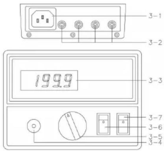
3. FRONT PANEL DESCRIPTION
text_image
3-1 3-2 1999 3-3 3-7 3-6 3-5 3-4Fig. 1
3-1 AC Power Input Socket
3-2 4 Wires Input Terminal
3-3 Display
3-4 Zero Adjust Knob
3-5 Power Off/Range Rotary Switch
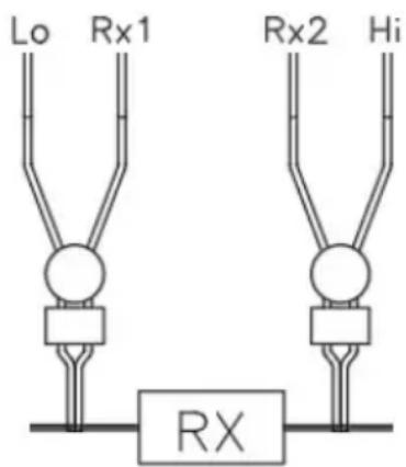
4. BASIC 4 WIRES MEASURING PRINCIPLE
The DIGITAL MILLIOHM METER is the precision, wide range & small resistance with high resolution measuring instrument. As for preventing any measuring errors, especial to avoid the influence of "LEAD STRAY RESISTANCE" or "TEST WIRE'S RESISTANCE". The meter is designed according the following "4 WIRES MEASURING PRINCIPAL" to let the meter within high accuracy.
text_image
Lo Rx1 Rx2 Hi RXFig. 2
* Please refer to 2-2 Electrical Specification (page 2), each range exist the exciting test current (from Hi to Lo terminal).
* The standard current is dropped to the unknown resistor Rx.
* From the terminal Rx1, Rx2 can measure a voltage : Vx = Is x Rx.
* According the Vx value, then meter can get the unknown resistance (Rx) values from following formula :
$$ \begin{array}{c} \text {Rx = Vx} \ \text {Is} \end{array} $$
* The measured resistance between Rx 1 and Rx 2 is not affected by any stray resistance of test wire.
5. PRECAUTION & PREPARATIONS FOR MEASUREMENT
* Please check carefully if the meter's power supply is AC 110 V or AC 220 V before operating the meter. There is a label at the rear of the meter to show the proper power source outlet AC 110 V or AC 220 V.
* Please don't input voltage to input terminal (Lo, Rx1, Rx2, Hi) to prevent any internal circuit damage.
6. MEASURING PROCEDURES
1) Rotate the "Power off/Range Rotary Switch" (3-5, Fig. 1) to the convenient & right range 200 m ohm, 2000 m ohm, 20 ohm, 200 ohm, 2000 ohm.
2) After select the above right range, then should make the following "ZERO ADJ. PROCEDURE":
a. Short the 2 clips.
b. Rotate the "Zero Adjust Knob" (3-4, Fig. 1) until the display reading values show the zero values.
Consideration :
* Zero adjustment is necessary for range 200 m ohm, 2000 m ohm, 20 ohm only.
* Recommend user select 200 m ohm range to make "ZERO ADJ. PROCEDURE"
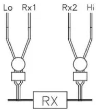
3) Connect the 2 clips as following Fig. 3 to measure the unknown resistance.
text_image
Lo Rx1 Rx2 Hi RXFig. 3
4) Connect the 2 Kelvin clips as following Fig. 4 to measure the unknown resistance between two test points, such as PCB layout.

text_image
Lo Rx1 Rx2 HiFig. 4