MTS500 - Measurement PCE Instruments - Free user manual and instructions
Find the device manual for free MTS500 PCE Instruments in PDF.

User questions about MTS500 PCE Instruments
0 question about this device. Answer the ones you know or ask your own.
Ask a new question about this device
Download the instructions for your Measurement in PDF format for free! Find your manual MTS500 - PCE Instruments and take your electronic device back in hand. On this page are published all the documents necessary for the use of your device. MTS500 by PCE Instruments.
USER MANUAL MTS500 PCE Instruments
Southpoint Business Park
Ensign way
Hampshire / Southampton
United Kingdom, SO31 4RF
From outside UK: +44
Tel: (0) 2380 98703 0
Fax: (0) 2380 98703 9
info@pce-instruments.com
www.pce-instruments.com/english
www.pce-instruments.com
Test Stand for Force Gauge
PCE-MTS500
INSTRUCTION MANUAL

natural_image
Laboratory testing setup with spring and test stand (no visible text or symbols on main components)CONTENTS
3&(0 76) Electric Vertical Test Stand, applied in tension and compression test, is assembled with (2N-5kN) Series Force Gauge. The stand adopts double-column construction with good stability, wide application range and easy operation. Furthermore, it has advantages of non-polar speed adjustment, manual or automatic operation, suitable for fields of rubber & plastic products, textile, construction, complex material, wire & cables, auto accessories, engine and scientific research, etc.
Note: When installing different force gauge, it should equip different backboard.
2. Structure
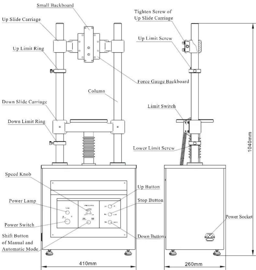
text_image
Small Backboard Up Slide Carriage Up Limit Ring Column Tighten Screw of Up Slide Carriage Up Limit Screw Force Gauge Backboard Down Slide Carriage Down Limit Ring Limit Switch Lower Limit Screw Speed Knob Power Lamp Power Switch Shift Button of Manual and Automatic Mode 410mm 1040mm Up Button Stop Button Down Button Power Socket 260mm3. Installation of Force Gauge

text_image
Force Gauge M3 Screw Force Gauge M6 Iaxangular Nut Joint Bearing Outside Backboard SensorPicture 1 Installationof (Sensor Inside) ForceGauge
Picture 2 Installation of Force Gauge
Picture 3 Installation of Force Gauge(1kN-5kN)
-
When installing (Sensor Inside) Force Gauge, take out 4 pieces of M3 screws from toolbox, and through 4 deep hole of Small Backboard, tighten them into 4 installing hole on force gauge(Picture 1);
-
When installing Force Gauge, take off 4 pieces of M6 hexangular screws of back cover, and backboard. also take off Small Backboard on test stand; through 4 hole of Force Gauge backboard, tighten 4 pieces of M6 screws into insalling hole of Force Gauge by nut (Picture 2);
-
When installing (1kN-5kN) Force Gauge, it should equip the SJ-021 Outside Backboard. Loosen the 4 pieces of M6 hexangular screws, take off the SKN Backboard, fix the SJ-021 Backboard on the position of Force Gauge Backboard by the 4 screws; Take one of the joint axletree from sensor toolbox, and tighten the sensor through hole of backboard as showing in picture(Picture 3).
4. Specification
| Capacity | ( | |
| Measuring Stroke | ||
| Measuring Speed | ||
| Maximum Gap | ||
| Work Voltage | ||
| Rate Current | ||
| Fuse of Main Circuit | ||
| Fuse of Controlling Circuit | ||
| Working Temperature | ± °C | |
| Store & Delivery Temperature | °C | °C |
| Relative Humidity |
5.Attention
A. Please do not take Up or Lower Limit Screw at any time to prevent screw mandrel from getting out or damaging to other accessories.
B. When needing to move UP Slide Carriage for appropriate space, please pay attention:
-
Loosen the tighten screw at two side of Up Slide Carriage, during which it should support the slide carriage by hands to avoid dropping down.
-
The Up Slide Carriage will not upper than the top of column, and lower than Up Limit Screw.
c. Operation
Examine Before Operation
A. Check Tighten Screw of Up Slide Carriage to be locked firmly;
B. Turn on the power switch, then the power lamp will be light.
C. Examine the stand whether there is abnormal sound when moving without load.
Manual Test
Choose the Manual mode by pressing Shift Button of Manual and Automatic Mode; Press Up or Down button all along, the test stand will work; Loosen the button, the test stand will stop work and finish test.
Automatic Test
Choose the Automatic mode by pressing Shift Button of Manual and Automatic Mode; Press Up or Down button once, the test stand will work; Press Stop button, the test stand will stop and finish test.
7. Maintenance
A. Please keep the environment clean and prevent liquid and metal scraps from entering the engine box, otherwise electric shock may happen and driving components may be damaged.
B. Please keep the column and lower slide carriage hole clean.
C. Add some lubricant to screw mandrel and gear after period of time.
D. Please pull out power connector, and make the stand away from dust and moisture if it is not used.
8. Packing List
| Number | Parts Name | Quantity |
| 1 | 3&(0 76 Main Body | 1 |
| 2 | M10 Inner Hexagon Spanner | 1 |
| 3 | 1 | |
| 4 | 110/220V Power Wire | 1 |
| 5 | Manual | 1 |
| 6 | Qualification Certificate | 1 |