W-3005 - Intercom VIKING - Free user manual and instructions
Find the device manual for free W-3005 VIKING in PDF.

User questions about W-3005 VIKING
0 question about this device. Answer the ones you know or ask your own.
Ask a new question about this device
Download the instructions for your Intercom in PDF format for free! Find your manual W-3005 - VIKING and take your electronic device back in hand. On this page are published all the documents necessary for the use of your device. W-3005 by VIKING.
USER MANUAL W-3005 VIKING
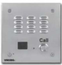
Vandal Resistant Handsfree Doorbox with Built-In Color Video Camera
Answer your door or gate from the safety of your telephone!
The W-3005 is a weather resistant, handsfree video doorbox designed to provide quick and reliable handsfree communication and CCTV video of who is at your door or gate. The W-3005 can interface directly with the unused telephone line input of nearly any phone system. One or two doorboxes can also share an existing residential phone line when used with a C-1000B doorbox controller.
When the "Call" button is pressed, the doorbox generates a standard or custom ring cadence of an adjustable number of rings. For noisy environments, the doorbox's new louder speaker output and "Push-to-Talk" feature can be used.
The W-3005-EWP shares all of the features of the W-3005 in addition to Enhanced Weather Protection (EWP) for outdoor installations where the unit is exposed to precipitation or
Features
• Built-in high resolution color video camera with wide viewing angle, tilt/swivel adjustments and wide operating temperature
• Audio and video transmission on one CAT5E cable
- Vandal Resistant Features: 14 gauge louvered 316 marine grade stainless steel faceplate with permanent laser etched graphics, stainless steel speaker/mic screen, heavy duty metal "Call" button, scratch resistant powder coating (optional VE-5x5) and hexdrive mounting screws
- Weather Resistant Features: Marine grade 316 stainless steel faceplate, screws and and push button switch. Switch internally sealed per IP67. Mylar speaker. Self-draining mic mount. Faceplate, mic and speaker gaskets. Weather resistant powder paint on optional VE-5x5.
• Volume adjustments for microphone and speaker
• Blue call progress / night light LED
• High output speaker amplifier with volume adjustment POT
• 40 volt talk battery
• 20 Hz ring generator (6.0 REN ring load maximum)
- Selectable ring cadence (standard, double, short/short/long, or short/long/short)
- Selectable number of rings (2, 3, 10 or 30)
- Selectable "Push-to-Talk" feature for noisy environments
- W-3005-EWP is designed to meet IP66 Ingress Protection Rating (see DOD 859 for more information)
- Connect to a phone system's unused trunk input, FXO port or a Viking C-1000B Controller
text_image
Call VIXCING.W-3005 Brushed 316 Stainless Steel
text_image
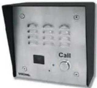
Call V10CAMLW-3005 shown with optional VE-5x5 Surface Mount Box
condensation. EWP products feature foam rubber gaskets and boots, sealed connections, gel-filled butt connectors, as well as urethane or thermal plastic potted circuit boards with internally sealed, field-adjustable trim pots and DIP switches for easy on-site programming. For more information, see DOD 859.
Applications
- Ideal for noisy locations in "Push-to-Talk" mode
• Commercial, industrial or residential door security
• Door or gate communication
• Truck stop/gas station fuel island communication - Use with the C-1000B controller for single line residential systems or when the operation of door strikes or gate openers is necessary (see DOD 155)
www.VikingElectronics.com Information: 715-386-8861
Specifications
Power: 120V AC/13.8V AC 1.25A UL listed adapter provided
Dimensions: Overall - 5.0" x 5.0" x 2.25" (127mm x 127mm x 57.2mm) Plastic Rough-In Box - 4.0" x 4.0" x 2.12" (102mm x 102mm x 54mm)
Shipping Weight: 3.2 lbs (1.45 Kg)
Operating Temperature: -15°F to 130°F (-26°C to 54°C)
Humidity: W-3005 - 5% to 95% non-condensing humidity, W-3005-EWP - Up to 100% condensing humidity
Connections: (7) Gel filled butt connectors (3M Scotchlok UR2)
(See page 2 for complete specifications)
Doorbox Specifications
Power: 120V AC/13.8V AC 1.25A UL listed adapter provided
Dimensions: Overall - 127mm x 127mm x 57.2mm (5.0" x 5.0" x 2.25") Plastic Rough-In Box - 102mm x 102mm x 54mm (4.0" x 4.0" x 2.12")
Shipping Weight: 1.81 Kg (4 lbs)
Ringer Output: 20 Hz, 6.0 REN load maximum
Maximum Loop Length: 1.9 Km (6300 ft) - 24 AWG twisted pair
Maximum Power Run with CAT5E Wire: 1 pair = 150 ft, 2 pair = 300 ft, 3 pair = 450 ft
Note: Power run length may be increased, see Wiring section.
Camera Specifications-
Power: 6-22V DC 150mA (12V DC UL Listed adapter included)
Image Sensor: 1/4" color CMOS
Video Output: 1 VP-P composite, NTSC, 75 ohms
Resolution: 420 lines (640 x 480 @ 30fps / 307,200 pixels)
Sensitivity: 0.025 LUX (50 IRE) F 1.2 3200K
Lens: 2.1mm, conical pinhole
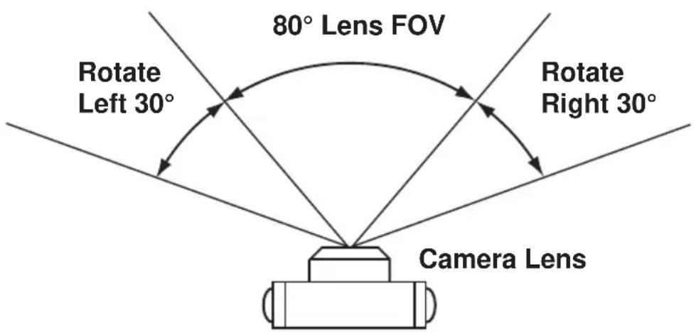
FOV (Field of View): 80° Horizontal, 60° Vertical, 100° Diagonal
Tilt/Swivel Adjustment: Vertical +/- 20°, horizontal +/- 30° (see Diagram A below)
IR Compatibility: This camera is equipped with an OLP (Optical Low Pass) filter to maintain correct video color in outside applications. The standard camera is NOT compatible with IR illuminators. If IR illumination is required, you will need to replace the existing camera with a Viking model VCAM-1IR. For more information, see DOD# 190.
Maximum Wire Run Length: 1000 ft with *RG59/RG6 for video and CAT5 for power (1 pair) and entry phone audio (1 pair). 150 ft with CAT5E for video, power and entry phone audio (longer video runs are possible by using video balun transceivers, see Installation section F, page 5).
* Note: RG59 or RG6 with solid center conductor and 95% bare copper braid shield.
Doorbox / Camera Specifications
Operating Temperature: -26^ C to 54^ C ( -15^ F to 130^ F)
Humidity: Standard model: 5% to 95% non-condensing, EWP model: Up to 100%
Connections: (5) gel-filled butt connectors (3M Scotchlok UR2)
Recommended Surface Mount Box: Viking model VE-5x5 (DOD# 424)
Diagram A
Camera Horizontal Field of View:
text_image
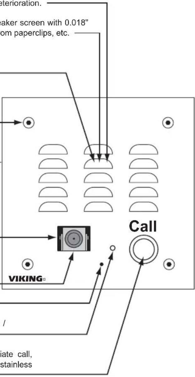
80° Lens FOV Rotate Left 30° Rotate Right 30° Camera LensSpeaker: Mylar speaker with rubber gasket to maintain water-tight seal and eliminate water deterioration.
Speaker Screen: Stainless steel speaker screen with 0.018" diameter holes to prevent punctures from paperclips, etc.
Microphone: Omni-directional microphone with protective water-resistant cloth.
Mounting Screws: (4) 6-32 x 3/4" Marine grade 316 stainless steel, flat head, 5/64" hexdrive screws (included).
Faceplate: 14 gauge Marine grade 316 stainless steel faceplate.
Color Video Camera: Wide operating temperature range of -30°F to 150°F, NTSC composite video output with 420 lines of resolution, 80° wide viewing angle lens, tilt and swivel adjustments for aiming towards visitors.
Protective Camera Window: Impact resistant polycarbonate lens with scratch resistant coating and water-tight gasket.
Condensation Drain Hole
LED: Lights blue for "Call Progress / Night Light" indication.
Push Button Switch: Push to initiate call, push again to disconnect. Solid 316 stainless steel internally sealed per IP67.
text_image
deterioration. maker screen with 0.018" om paperclips, etc. VIKING® Call / late call, stainless
text_image
Speaker Volume Microphone Volume Earth Ground: To increase surge protection, loosen the screw labeled (as shown) and fasten a wire with spade terminal (included) from the mounting screw to Earth Ground (grounding rod, water pipe, etc.) S1 DIP Switches (see page 7): S2 DIP Switches (see page 7): Faceplate Gasket: 1/8" thick closed cell PVC to provide a water-tight seal.IMPORTANT: Electronic devices are susceptible to lightning and power station electrical surges from both the AC outlet and the telephone line. It is recommended that a surge protector be installed to protect against such surges.
A. Mounting
Caution: When warm air comes in contact with cold surfaces, such as outside walls, it causes condensation. To help prevent condensation from accumulating inside the W-3005, bring conduit into the bottom of the unit. If this is not possible, drill a 1/4" diameter hole in the bottom of the plastic rough-in box.
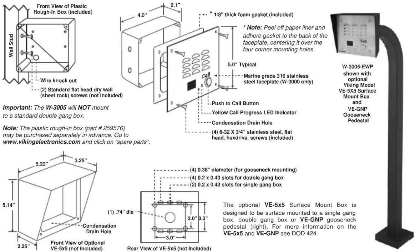
Important: The W-3005 will NOT mount to a standard double gang box.
Note: The plastic rough-in box (part # 259576) may be purchased separately in advance. Go to www.vikingelectronics.com and click on "spare parts".
The optional VE-5x5 Surface Mount Box is designed to be surface mounted to a single gang box, double gang box or VE-GNP gooseneck pedestal (right). For more information on the VE-5x5 and VE-GNP see DOD 424.
B. Wiring

text_image
Wiring (Spade connector included) ** Earth Ground (optional) Rear View of the W-3005 120V AC *** 13.8VAC (18VAC max) Red/Black Black/Red Green (Tip) Red (Ring) CAUTION: Do NOT install a W-3005 on a telephone line without a C-1000B Controller (see DOD 155). * Gel-Filled Butt Connectors Unused PABX/KSU Trunk Input Single Line Phone OR Multi-Line Phone C-O. Line TO 2nd Doorbox VIKING MODEL C-1000B DOOR ENTRY: CCTV VIDEO CONTROLLER Viking HUSTROOMER HUDSON, TO 3466 120V AC 120V AC 120V AC 120V AC 120V AC 120V AC 120V AC 120V AC 120V AC 120V AC 120V AC 120V AC 120V AC 120V AC 120V AC 120V AC 120V AC 125V AC 125V AC 125V AC 125V AC 125V AC 125V AC 125V AC 125V AC 125V AC 125V AC 125V AC 125V AC 125V AC 125V AC 125V AC 125V AC 125V AC * Note: The gel-filled (water-tight) butt connectors are designed for insulation displacement on 19-26 guage wire with a maximum insulation of 0.082 inches. Cut off stripped wire ends prior to terminating. C-1000B Controller** Note: To increase surge protection, loosen the PCB mounting screw labeled ⏻ (as shown above) and fasten a wire with spade terminal (included) from the mounting screw to Earth Ground (grounding rod, water pipe, etc.)
*** Warning: The power run wire length is limited to 150 ft of CAT5 wire. Longer power runs will require heavier gauge wire (doubling or tripling pairs) and/or a higher voltage power adapter. Voltage at the doorbox power input connections must not exceed 18VAC RMS.
C. Using W-3005(s) and a C-1000B on a DSL Line
The C-1000B can be installed on a DSL line by using a DSL PJ31X Alarm Filter and single line DSL filters.

flowchart
graph TD
    A["Model C-1000B (not included)"] --> B["VIKING © MODEL C-1000B"]
    B --> C["DOOR ENTRY / CCTV VIDEO / PAGING CONTROLLER"]
    C --> D["Cut & Strip back jacket"]
    C --> E["Cat 5 Wire"]
    C --> F["RJ45X"]
    F --> G["Brown/White"]
    G --> H["Blue/White (Inside pair)"]
    G --> I["Green/White"]
    G --> J["White/Orange (Outside pair)"]
    C --> K["Red LINE IN (Inside pair)"]
    K --> L["Green"]
    L --> M["Brown"]
    M --> N["Line OUT (Outside pair)"]
    M --> O["Gray"]
    C --> P["** Standard DSL Filter"]
    P --> Q["Doorbox 2 Model W-3005"]
    P --> R["Doorbox 1 Model W-3005"]
    P --> S["Computer"]
    P --> T["Phone 1"]
    P --> U["Phone 2"]
    style A fill:#f9f,stroke:#333
    style B fill:#ccf,stroke:#333
    style C fill:#cfc,stroke:#333
    style D fill:#fcc,stroke:#333
    style E fill:#cff,stroke:#333
    style F fill:#ffc,stroke:#333
    style G fill:#fcc,stroke:#333
    style H fill:#fcf,stroke:#333
    style I fill:#cff,stroke:#333
    style J fill:#ffc,stroke:#333
    style K fill:#fcc,stroke:#333
    style L fill:#cff,stroke:#333
    style M fill:#ffc,stroke:#333
    style N fill:#fcc,stroke:#333
    style O fill:#ffc,stroke:#333
    style P fill:#fcc,stroke:#333
    style Q fill:#fcf,stroke:#333
    style R fill:#cff,stroke:#333
    style S fill:#ffc,stroke:#333
Recommended DSL Filters:
* Excelsus Z-Blocker Alarm Panel DSL Filter Z-A431PJ31X-A
** Excelsus Z-Blocker Single Line DSL Filter Z-275P2J
For technical information or to buy Excelsus Filters, go to www.excelsus-tech.com
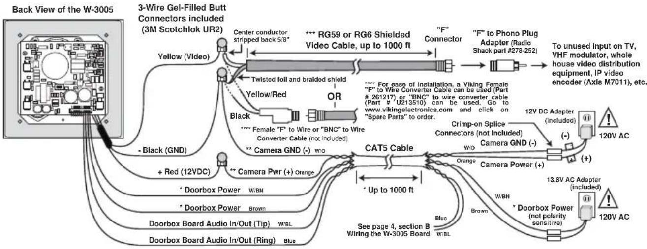
D. Wiring the W-3005 Camera
1. Using RG59 for Video and CAT5 for Camera Power and Phone Board Audio (Recommended)
flowchart
graph TD
    A["Back View of the W-3005"] --> B["3-Wire Gel-Filled Butt Connectors included (3M Scotchlok UR2)"]
    B --> C["Center conductor stripped back 5/8""]
    B --> D["Twisted foil and braided shield"]
    B --> E["Yellow/Red"]
    B --> F["Black"]
    B --> G["Or"]
    B --> H["** Female "F" to Wire or "BNC" to Wire Converter Cable (not included)"]
    B --> I["** Camera GND (-) w/o"]
    B --> J["Cat5 Cable"]
    J --> K["Crimp-on Splice Connectors (not Included)"]
    J --> L["Camera GND (-)"]
    J --> M["Orange"]
    J --> N["Camera Power (+)"]
    J --> O["See page 4, section B Wiring the W-3005 Board"]
    B --> P["+ Red (12VDC)"]
    B --> Q["* Doorbox Power w/BN"]
    B --> R["* Doorbox Power Brown"]
    B --> S["Doorbox Board Audio In/Out (Tip) w/BL"]
    B --> T["Doorbox Board Audio In/Out (Ring) Blue"]
    B --> U["Up to 1000 ft"]
    B --> V["To unused Input on TV, VHF modulator, whole house video distribution equipment, IP video encoder (Axis M7011), etc."]
    B --> W[""F" Connector"]
    W --> X[""F" to Phono Plug Adapter (Radio Shack part #278-252)"]
    X --> Y["12V DC Adapter (included)"]
    Y --> Z["(-)"]
    Y --> AA["(+)"]
    Y --> AB["120V AC"]
    Y --> AC["13.8V AC Adapter (included)"]
    Y --> AD["120V AC"]
* Warning: The doorbox power run wire length is limited to 150 ft of single pair 24 AWG CAT5E wire. Longer power runs will require heavier gauge wire (doubling pairs) and/or a higher voltage power adapter. Voltage at the doorbox power input connections must not exceed 18VAC RMS.
** Note: The maximum camera power supply wire run length is 1000 ft of 24 gauge wire (CAT 5/6), longer runs are possible by doubling pairs, increasing the wire gauge or using up to a 22V DC 200mA power adapter.
*** Note: RG59 or RG6 with solid center conductor and 95% bare copper braid shield.
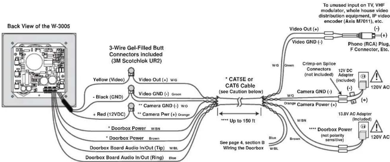
2. Using CAT5E or CAT6 for Video, Camera Power and Phone Board Audio (see Caution below)
flowchart
graph TD
    A["Back View of the W-3005"] --> B["3-Wire Gel-Filled Butt Connectors included (3M Scotchlok UR2)"]
    B --> C["Yellow (Video)"]
    B --> D["Black (GND)"]
    B --> E["Red (12VDC)"]
    B --> F["* Doorbox Power"]
    B --> G["* Doorbox Power"]
    B --> H["Doorbox Board Audio In/Out (Tip)"]
    B --> I["Doorbox Board Audio In/Out (Ring)"]
    B --> J["Blue"]
    B --> K["Orange"]
    B --> L["Image Cable"]
    B --> M["Image Cable"]
    B --> N["Image Cable"]
    B --> O["Image Cable"]
    B --> P["Image Cable"]
    B --> Q["Image Cable"]
    B --> R["Image Cable"]
    B --> S["Image Cable"]
    B --> T["Image Cable"]
    B --> U["Image Cable"]
    B --> V["Image Cable"]
    B --> W["Image Cable"]
    B --> X["Image Cable"]
    B --> Y["Image Cable"]
    B --> Z["Image Cable"]
    B --> AA["Image Cable"]
    B --> AB["Image Cable"]
    B --> AC["Image Cable"]
    B --> AD["Image Cable"]
    B --> AE["Image Cable"]
    B --> AF["Image Cable"]
    B --> AG["Image Cable"]
    B --> AH["Image Cable"]
    B --> AI["Image Cable"]
    B --> AJ["Image Cable"]
    B --> AK["Image Cable"]
    B --> AL["Image Cable"]
    B --> AM["Image Cable"]
    B --> AN["Image Cable"]
    B --> AO["Image Cable"]
    B --> AP["Image Cable"]
    B --> AQ["Image Cable"]
    B --> AR["Image Cable"]
    B --> AS["Image Cable"]
    B --> AT["Image Cable"]
    B --> AU["Image Cable"]
    B --> AV["Image Cable"]
    B --> AW["Image Cable"]
    B --> AX["Image Cable"]
    B --> AY["Image Cable"]
    B --> AZ["Image Cable"]
    B --> BA["Image Cable"]
    B --> BB["Image Cable"]
    B --> BC["Image Cable"]
    B --> BD["Image Cable"]
    B --> BE["Image Cable"]
    B --> BF["Image Cable"]
    B --> BG["Image Cable"]
    B --> BH["Image Cable"]
    B --> BI["Image Cable"]
    B --> BJ["Image Cable"]
    B --> BK["Image Cable"]
    B --> BL["Image Cable"]
    B --> BM["Image Cable"]
    B --> BN["Image Cable"]
    B --> BO["Image Cable"]
    B --> BP["Image Cable"]
    B --> BQ["Image Cable"]
    B --> BR["Image Cable"]
    B --> BS["Image Cable"]
    B --> BT["Image Cable"]
    B --> BU["Image Cable"]
    B --> BV["Image Cable"]
    B --> BW["Image Cable"]
    B --> BX["Image Cable"]
    B --> BY["Image Cable"]
    B --> BZ["Image Cable"]
    B --> CA["Image Cable"]
    B --> CB["Image Cable"]
    B --> CC["Image Cable"]
    B --> CD["Image Cable"]
    B --> CE["Image Cable"]
    B --> CF["Image Cable"]
    B --> CG["Image Cable"]
    B --> CH["Image Cable"]
    B --> CI["Image Cable"]
    B --> CJ["Image Cable"]
    B --> CK["Image Cable"]
* Note: Up to 150 ft video cable run length can be achieved using CAT5E or CAT6 cable. Longer cable runs can be used if a passive or active video Balun transceiver is used on each end of the cable. Generally, passive transceivers can achieve up to 750 ft cable runs where active transceivers can achieve up to 3000 ft runs depending on cable type, etc. The type of video balun transceiver required is specific to your cable run length. For more information on video balun transceivers go to: www.northernvideo.com.
** Note: The maximum camera power supply wire run length is 1000 ft of 24 gauge wire (CAT 5/6), longer runs are possible by doubling pairs, increasing the wire gauge or using up to a 22V DC 200mA power adapter.
*** Note: RG59 or RG6 with solid center conductor and 95% bare copper braid shield.
*** Warning: The doorbox power run wire length is limited to 150 ft of single pair 24 AWG CAT5E wire. Longer power runs will require heavier gauge wire (doubling pairs) and/or a higher voltage power adapter. Voltage at the doorbox power input connections must not exceed 18VAC RMS.
Caution: When routing CAT5E or CAT6 cable, maintain a minimum distance of 3 ft from any parallel high voltage wire (110 VAC) and a minimum of 2 ft from crossing any high voltage wire. For installations where RF noise is expected (commercial applications) or wire runs are near high voltage (110 VAC) wires, a shielded video cable such as RG6 is recommended.
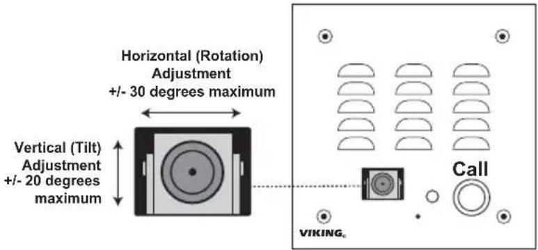
E. Adjusting the Camera
The camera can be tilted and rotated to your desired position. A portable service (test) monitor can be used to determine the correct viewing angle during installation.
Important: To prevent the edge of the faceplate from being viewed in the video image, do not rotate the camera beyond 30 degrees or tilt beyond 20 degrees.
text_image
Horizontal (Rotation) Adjustment +/- 30 degrees maximum Vertical (Tilt) Adjustment +/- 20 degrees maximum Call VIKINGProgramming
A. DIP Switches

text_image
S1 DIP Switches ON 1 2 3 OFF S2 DIP Switches ON 1 2 OFFNote: All switches shown in factory default settings.
S1 DIP Switch Settings
| Switch 1 | Switch 2 Ring Output |
| OFF OFF 2 rings | |
| ON OFF 3 rings | |
| OFF ON 10 rings (default) | |
| ON ON 30 rings | |
| Switch 3 | Communication Mode |
| OFF Normal Handsfree Mode (default) | |
| ON Push-To-Talk Mode | |
S2 DIP Switch Settings
| Switch 1 | Switch 2 R | ng Cadence |
| OFF OFF Standard: 1 sec on, 3 secs off (default) | ||
| ON OFF Double: 1 sec on, 0.5 sec off, 1 sec on, 3.5 sec off | ||
| OFF | ON | Short/Short/Long: 0.5 sec on, 0.5 sec off, 0.5 sec on, 0.5 off, 1 sec on, 3 secs off |
| ON ON | Short/Long/Short: 0.5 sec on, 0.5 sec off, 1 sec on, 0.5 sec off, 0.5 sec on, 3 secs off | |
B. Handsfree Operation (S1 Dip Switch 3 - OFF)
When the "Call" button is pressed, the call progress LED will turn off and the W-3005 will begin generating a 20 Hz ring signal. The caller at the W-3005 will hear an audio ring back signal while the LED flashes. When the inside party has answered, the LED will light until the inside party hangs up. At that point, the LED will turn off for approximately one second and then light steady to illuminate the W-3005 after dark.
C. Push-To-Talk Operation (S1 Dip Switch 3 - ON)
In extremely noisy locations, the "Push-to-Talk" mode should be used. To switch to the "Push-to-Talk" mode, place DIP switch 3 in the ON position (see Dip Switch Programming). To initiate a call, momentarily press the "Call" button to generate the ring signal. After the inside party has answered, press and hold the call button to talk. Release the call button to listen.
D. Microphone and Speaker Volume Adjustment POTs
In certain noisy locations, the microphone volume may need to be decreased. A microphone POT (see right) is provided on the W-3005's circuit board to increase or decrease the microphone volume. However, in extremely noisy locations the microphone POT adjustment may not be enough to allow two-way talk path. In this case the "Push-to-Talk" mode should be used as shown above (see section C above).
Note: Both POTs come factory set in the middle position. A speaker volume POT is also provided for increasing or decreasing the speaker audio as needed.
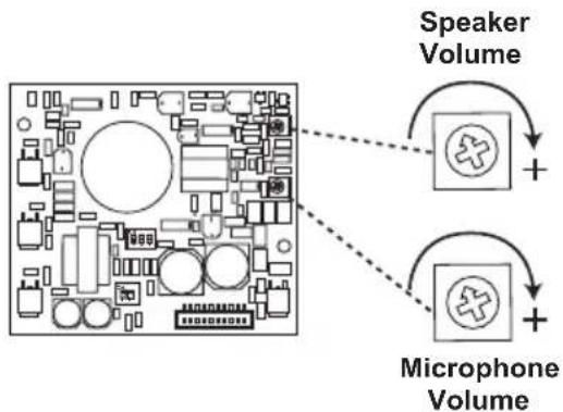
flowchart
graph TD
    A["Speaker Volume"] --> B["+"]
    C["Microphone Volume"] --> D["+"]
Operation
In the idle state, the W-3005 provides 24V DC talk battery. The LED remains lit for night time visibility. When the "Call" button is pressed, the W-3005 generates a standard or custom ring cadence (adjustable from 2-30 rings). The LED will turn off and then begin flashing during ringing. When the call is answered, ringing will stop and the LED will light steady. When the called party hangs up, the LED will turn off momentarily and then remain lit for the idle state. The W-3005 color video camera operates completely independently of the W-3005 Doorbox. With power supplied to the camera, it will continuously output a video signal.
Warranty
IF YOU HAVE A PROBLEM WITH A VIKING PRODUCT, CONTACT: VIKING TECHNICAL SUPPORT AT 715-386-8666
Our Technical Support Department is available for assistance Monday through Friday 8am - 5pm central time. So that we can give you better service, before you call please:
- Know the model number, the serial number and what software version you have (see serial label).
- Have your Product Manual in front of you.
- It is best if you are on site.
RETURNING PRODUCT FOR REPAIR
The following procedure is for equipment that needs repair:
- Customer must contact Viking's Technical Support Department at 715-386-8666 to obtain a Return Authorization (RA) number. The customer MUST have a complete description of the problem, with all pertinent information regarding the defect, such as options set, conditions, symptoms, methods to duplicate problem, frequency of failure, etc.
- Packing: Return equipment in original box or in proper packing so that damage will not occur while in transit. Static sensitive equipment such as a circuit board should be in an anti-static bag, sandwiched between foam and individually boxed. All equipment should be wrapped to avoid packing material lodging in or sticking to the equipment. Include ALL parts of the equipment. C.O.D. or freight collect shipments cannot be accepted. Ship cartons prepaid to: Viking Electronics, 1531 Industrial Street, Hudson, WI 54016
- Return shipping address: Be sure to include your return shipping address inside the box. We cannot ship to a PO Box.
- RA number on carton: In large printing, write the R.A. number on the outside of each carton being returned.
RETURNING PRODUCT FOR EXCHANGE
The following procedure is for equipment that has failed out-of-box (within 10 days of purchase):
- Customer must contact Viking's Technical Support at 715-386-8666 to determine possible causes for the problem. The customer MUST be able to step through recommended tests for diagnosis.
- If the Technical Support Product Specialist determines that the equipment is defective based on the customer's input and troubleshooting, a Return Authorization (R.A.) number will be issued. This number is valid for fourteen (14) calendar days from the date of issue.
- After obtaining the R.A. number, return the approved equipment to your distributor, referencing the R.A. number. Your distributor will then replace the product over Viking using the same R.A. number.
- The distributor will NOT exchange this product without first obtaining the R.A. number from you. If you haven't followed the steps listed in 1, 2 and 3, be aware that you will have to pay a restocking charge.
TWO YEAR LIMITED WARRANTY
Viking warrants its products to be free from defects in the workmanship or materials, under normal use and service, for a period of two years from the date of purchase from any authorized Viking distributor. If at any time during the warranty period, the product is deemed defective or malfunctions, return the product to Viking Electronics, Inc., 1531 Industrial Street, Hudson, WI., 54016. Customer must contact Viking's Technical Support Department at 715-386-8666 to obtain a Return Authorization (R.A.) number.
This warranty does not cover any damage to the product due to lightning, over voltage, under voltage, accident, misuse, abuse, negligence or any damage caused by use of the product by the purchaser or others. This warranty does not cover non-EWP products that have been exposed to wet or corrosive environments. This warranty does not cover stainless steel surfaces that have not been properly maintained.
NO OTHER WARRANTIES. VIKING MAKES NO WARRANTIES RELATING TO ITS PRODUCTS OTHER THAN AS DESCRIBED ABOVE AND DISCLAIMS ANY EXPRESS OR IMPLIED WARRANTIES OR MERCHANTABILITY OR FITNESS FOR ANY PARTICULAR PURPOSE.
EXCLUSION OF CONSEQUENTIAL DAMAGES. VIKING SHALL NOT, UNDER ANY CIRCUMSTANCES, BE LIABLE TO PURCHASER, OR ANY OTHER PARTY, FOR CONSEQUENTIAL, INCIDENTAL, SPECIAL OR EXEMPLARY DAMAGES ARISING OUT OF OR RELATED TO THE SALE OR USE OF THE PRODUCT SOLD HEREUNDER.
EXCLUSIVE REMEDY AND LIMITATION OF LIABILITY. WHETHER IN AN ACTION BASED ON CONTRACT, TORT (INCLUDING NEGLIGENCE OR STRICT LIABILITY) OR ANY OTHER LEGAL THEORY, ANY LIABILITY OF VIKING SHALL BE LIMITED TO REPAIR OR REPLACEMENT OF THE PRODUCT, OR AT VIKING'S OPTION, REFUND OF THE PURCHASE PRICE AS THE EXCLUSIVE REMEDY AND ANY LIABILITY OF VIKING SHALL BE SO LIMITED.
IT IS EXPRESSLY UNDERSTOOD AND AGREED THAT EACH AND EVERY PROVISION OF THIS AGREEMENT WHICH PROVIDES FOR DISCLAIMER OF WARRANTIES, EXCLUSION OF CONSEQUENTIAL DAMAGES, AND EXCLUSIVE REMEDY AND LIMITATION OF LIABILITY, ARE SEVERABLE FROM ANY OTHER PROVISION AND EACH PROVISION IS A SEPARABLE AND INDEPENDENT ELEMENT OF RISK ALLOCATION AND IS INTENDED TO BE ENFORCED AS SUCH.
Product Support: 715-386-8666
Due to the dynamic nature of the product design, the information contained in this document is subject to change without notice. Viking Electronics, and its affiliates and/or subsidiaries assume no responsibility for errors and omissions contained in this information. Revisions of this document or new editions of it may be issued to incorporate such changes.