ELGT-BS-90-600-10P - Sensor Festo - Free user manual and instructions
Find the device manual for free ELGT-BS-90-600-10P Festo in PDF.

User questions about ELGT-BS-90-600-10P Festo
0 question about this device. Answer the ones you know or ask your own.
Ask a new question about this device
Download the instructions for your Sensor in PDF format for free! Find your manual ELGT-BS-90-600-10P - Festo and take your electronic device back in hand. On this page are published all the documents necessary for the use of your device. ELGT-BS-90-600-10P by Festo.
USER MANUAL ELGT-BS-90-600-10P Festo
natural_image
Technical line drawing of a rectangular mechanical component with mounting holes and internal channels (no text or symbols)FESTO
Operating instruction
Translation of the original instructions
Table of contents
1 Applicable documents....4
2 Safety....4
2.1 Safety instructions....4
2.2 Intended use.... 4
2.3 Training of qualified personnel....4
3 Additional information....4
4 Product overview.... 5
4.1 Product design....5
4.2 Function....6
5 Transport....6
6 Assembly....7
6.1 Safety....7
6.2 Mounting motor....7
6.3 Mounting axis....7
6.4 Mounting payload....9
6.5 Mounting sensor.... 10
7 Commissioning.... 10
8 Maintenance.... 12
8.1 Safety.... 12
8.2 Check reversing backlash.... 12
8.3 Cleaning axis.... 12
8.4 Lubricating axis.... 12
9 Fault clearance.... 14
10 Technical data.... 16
10.1 Technical data, mechanical.... 16
10.2 Characteristic curves of support distances.... 18
10.3 Characteristic speed curves.... 20
1 Applicable documents

All available documents for the product → www.festo.com/sp.
2 Safety
2.1 Safety instructions
- Observe the identifications on the product.
-Only use the product if it is in perfect technical condition. - Before working on the product: Switch off the power supply, ensure that it is off and secure it against being switched on again.
- Store the product in a cool, dry environment protected from UV and corrosion. Keep storage times short.
- Store the product in ambient conditions without oils, greases and grease-dissolving vapours.
2.2 Intended use
The axis positions payloads or moves external guides.
The axis is approved for slide operation.

natural_image
Simple line drawing of a beam with supports at both ends and an arrow indicating upward motion (no text or symbols)Fig. 1: Slide operation
2.3 Training of qualified personnel
Work on the product may only be carried out by qualified personnel who can evaluate the work and detect dangers. The qualified personnel have knowledge and experience in handling electric drives and axes.
3 Additional information
- Contact the regional Festo contact if you have technical problems → www.festo.com.
- Accessories and spare parts → www.festo.com/catalogue.
4 Product overview
4.1 Product design

text_image
3 4 5 6 987 11 10 12 13 14 2 1 15Fig. 2: Product design ELGT-BS
1 Drive hub
2 Threaded hole for motor mounting kit
3 Drive cover
4 Guide rail
5 Cover
6 Ball screw lubrication point
7 Threaded hole for payload
8 Centring hole for payload
9 Guide lubrication point
10 Slide
11 End cap
12 Slot for sensors
13 Slot for profile mounting
14 Profile
15 Slot for slot nut, threaded hole and centring hole
Transport
text_image
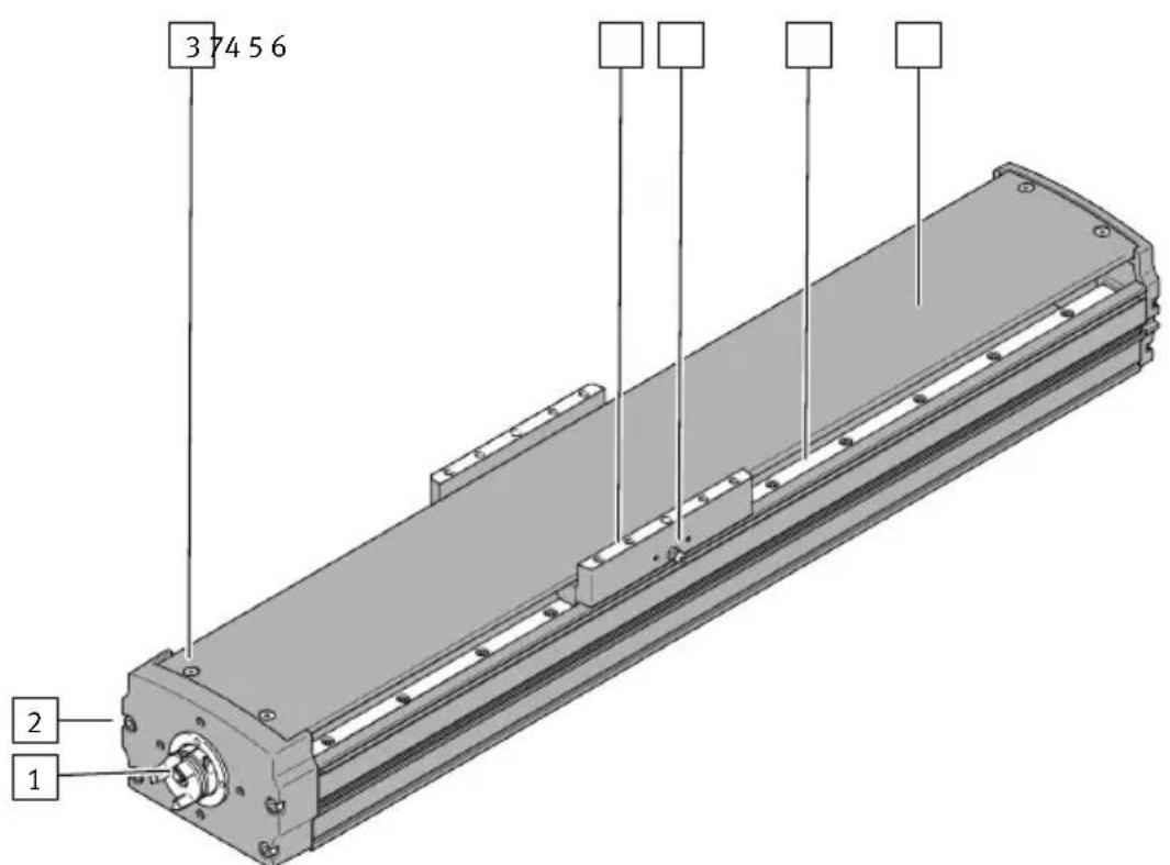
3 74 5 6 2 1Fig. 3: Surface ELGT-BS-...-AR
1 Drive hub, reflective surface
2 Drive cover retaining screw, reflective surface
3 Cover retaining screw, reflective surface
4 Attachment surface of the payload on the slide, reflective surface
5 Guide lubrication point, reflective surface
6 Guide rail and spindle, reflective surface
7 All other components, black anti-reflective surface
4.2 Function
The axis converts the rotary motion of the mounted motor into a linear motion of the slide. The screw drive converts the torque of the motor into a feed force. The linear movement of the slide is precisely guided by the guide. Sensors enable the monitoring of end positions, reference position and intermediate position.
5 Transport

WARNING
Risk of injury due to falling product
If the product is lifted incorrectly, it may fall and cut, crush or separate body parts.
- Lift the product only with suitable load-bearing equipment.
- Store and transport the product in its original packaging. Observe the weight, the dimensions and the ambient conditions.
-Take the centre of gravity of the product into consideration.
Assembly
- Store and transport the product in a horizontal position.
- Comply with the maximum permitted support clearances when attaching transportation aids 10.2 Characteristic curves of support distances. Compliance with the support clearances prevents the axis from excessive bending.
6 Assembly
6.1 Safety

WARNING
Risk of Injury due to Unexpected Movement of Components
For vertical or slanted mounting position: when power is off, moving parts can travel or fall uncontrolled into the lower end position.
- Bring moving parts of the product into a safe end position or secure them against falling.
6.2 Mounting motor
i
Observe the limit values for forces, torques and speeds if a non-recommended motor and motor mounting kit are used.
Axial kit Parallel kit
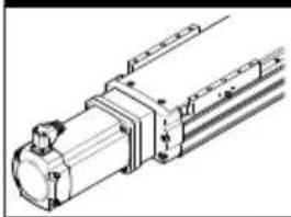
natural_image
Technical line drawing of a mechanical assembly with no visible text or symbols
natural_image
Technical line drawing of a mechanical component or housing (no text or symbols)Tab. 1: Motor mounting
- Mount the motor and motor mounting kit without tension.
6.3 Mounting axis
i
Axis with anti-reflective coating ELGT-BS-...-AR
- Recommendation: mount the axis with direct fastening or slot nut.
- Use only a hexagon socket tool with ball end for mounting the profile mounting EAHF-L2.
Profile mounting EAHF-L2 Slot nut NST Direct fastening
natural_image
Technical line drawings of three mechanical assembly configurations (no text or symbols)Tab. 2: Overview of mounting components
Requirements:
-Adequate clearance for payload to avoid collisions with motor, mounting components and sensor components.
- Sufficient space for maintenance work.
- Flatness of the mounting surface of 0.05% of the stroke length or maximum 0.5 mm over the stroke length of the bearing surface.
- Required support points lie within the specified support clearances 10.2 Characteristic curves of support distances. Compliance with the support clearances prevents the axis from excessive bending.
- Place the mounting components on the support points.
- Tighten the screws. Observe the maximum tightening torque and maximum screw-in depth.
i
When used in multi-axis systems: align to the first axis and install without tension.
| ELGT-BS-... -90 -120 -160 | |||
| Profile mounting EAHF-L2 | |||
| Thread Instruction manual | → www.festo.com/sp. | ||
| Slot nut mounting NST | |||
| Thread, bottom M5 M6 | |||
| Max. screw-in [mm] 6 depth t_max | 11.5 | ||
| Direct fastening | |||
| Thread, bottom M6 M8 | |||
| Max. tightening torque [Nm] 9.9 15 | |||
| Max. screw-in [mm] 8 depth t_max | 7 | 9 | |
| Cylindrical pins [mm] | ∅ 5 H7 | ∅ 6 H7 | ∅ 8 H7 |
6.4 Mounting payload

WARNING
Unexpected movement of components.
Injury due to impacts or crushing.
- Before working on the product, switch off the control and secure it to prevent it from being switched back on accidentally.

WARNING
Risk of Injury due to Unexpected Movement of Components
For vertical or slanted mounting position: when power is off, moving parts can travel or fall uncontrolled into the lower end position.
- Bring moving parts of the product into a safe end position or secure them against falling.

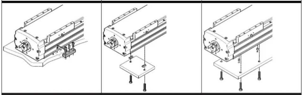
natural_image
Technical line drawing of a mechanical assembly with mounting flanges and bolts (no text or symbols)Fig. 4: Mounting payload, example "top mounting"
Requirements:
- Adequate clearance for payload to prevent collisions with motor, mounting components and sensor components.
- Sufficient space for maintenance work.
-A payload mounting surface flatness of 0.03 mm above the slide surface. -
Minimise the guide load. Short lever arms from the guide centre to the force application points and centres of gravity of the payload.
-
Place centring components in the centring holes.
- Position the payload at the intended location.
Commissioning
- Tighten the screws. Observe the maximum tightening torque and maximum screw-in depth.
| ELGT-BS-... -90 -120 -160 | |||
| Direct fastening | |||
| Thread M6 M8 | |||
| Max. tightening torque [Nm] 9.9 15 | |||
| Max. screw-in depth t_max [mm] 12 15 | |||
| Cylindrical pins [mm] ∅ 5 H7 ∅ 6 H7 ∅ | 8 H7 | ||
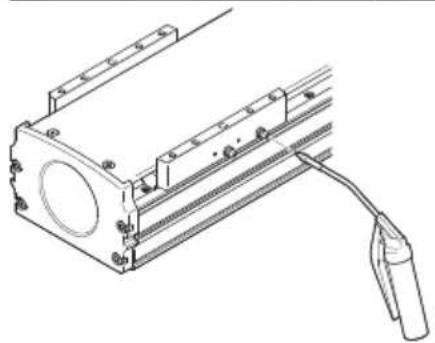
6.5 Mounting sensor
text_image
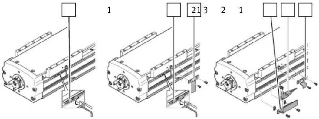
1 21 3 2 1Fig. 5: Mounting switch lug, sensor and sensor bracket
1 Sensor
3 Sensor bracket
2 Switch lug
Requirements:
- Protect the sensor from external magnetic or ferritic influences with min. 10 mm distance from slot nuts.
-
Use a hardware limit switch with N/C contact function to guarantee protection in the event of a sensor failure.
-
If necessary, mount the switch lug.
- If necessary, mount the sensor bracket.
- Mount the sensor.
7 Commissioning

WARNING
Risk of injury due to unexpected movement of components.
- Protect the positioning range from unwanted intervention.
- Keep foreign objects out of the positioning range.
- Perform commissioning with low dynamic response.
i
Block-shaped acceleration profiles without jerk limitation can have the following effects:
- High mechanical loads on the lead screw due to high force peaks.
- Overshooting effects during positioning.
- Rise of the entire system.
Recommendation: reduce high force peaks in the acceleration and deceleration phases by using the jerk limitation.
i
Identical axes can generate different running noises depending on the parameterisation, mode of operation, type of mounting, installation environment and components.
i
For use with reduced particle emission:
- Clean product 8.3 Cleaning axis.
Requirements:
- The motor encoder is referenced to the reference mark by a homing run.
- The motor encoder has the absolute reference to the reference mark.
- The direction of movement of the slide is determined by the direction of rotation of the motor.
- The mounting of the drive system has been checked.
- The installation on the motor has been checked.
- There are no foreign objects within the range of motion of the drive system.
–Maximum permissible feed force and drive torque as a function of acceleration, deceleration, e.g. with stop function or quick stop, speed, moving mass and mounting position, are not exceeded. - Axis is not mechanically overloaded and dynamic setpoint deviation is not exceeded as a result of force peaks, torque peaks or overshoot effects, e.g. overrunning the end position.
Overloads and overruns as a result of jerk limitation must be restricted by reduced acceleration and deceleration setpoints or optimised controller settings. - The software end positions are not within the effective range of the mechanical stops.
-
No homing or test run to mechanical end stops.
-
Start check run.
- Select permissible reference points "against reference switch" for the homing.
- Start the homing run with reduced speed setpoints, acceleration setpoints and deceleration setpoints.
- Start the test run with reduced speed setpoints, acceleration setpoints and deceleration setpoints.
- Check that the slide completes the entire travel cycle within the specified time.
The slide stops its travel when it reaches a limit switch and the drive system is ready for operation.
8 Maintenance
8.1 Safety

WARNING
Unexpected movement of components.
Injury due to impacts or crushing.
- Before working on the product, switch off the control and secure it to prevent it from being switched back on accidentally.
8.2 Check reversing backlash
- Check the reversing backlash (reversal error) of the slide at every maintenance interval, e.g. lubrication interval. If the maximum permissible reversing backlash is exceeded, replace the axis.
| ELGT-BS-... -90 -120 -160 | |||
| Max. permissible reversing backlash | [mm] 0.15 |
8.3 Cleaning axis
- If the guide rail is dirty, clean it with a clean, soft and lint-free cloth without cleaning agents and then apply the lubricant thinly to the guide rail.
- Clean the other product components with a clean, soft cloth and non-abrasive cleaning agents.
For use with reduced particle emission:
- Remove abraded particles and dirt from the product:
– Prior to initial commissioning.
- Regularly during operation.
8.4 Lubricating axis
Requirements:
-The pressure grease gun LUB-1, 647958, is available.
- The roller bearing grease LUB-KC1, 684474, Elkalub VP 922, is available.
- The lubrication adapter, axial output, LUB-1-KE, 744167, is available.
- Calculate the load comparison factor f_v with the formula for combined loads 10.1 Technical data, mechanical.
Maintenance
- Take the lubrication interval S_int as a function of the load comparison factor f_v from the characteristic curve.

line
| f_v | S_int [km] | | --- | --- | | 0.2 | 12500 | | 0.4 | 11500 | | 0.6 | 10000 | | 0.8 | 7500 | | 1.0 | 2000 |- Determine the load factors:
-Dusty and dirty environment.
-Nominal stroke < 300 mm or > 2000 mm.
-Ambient temperature > +40 °C.
- Service age > 3 years.
- The travel profile matches triangular operation, e.g. frequent acceleration and braking.
-
If there is a load factor, halve the lubrication interval S_int . If there are multiple load factors, reduce the lubrication interval S_int to a quarter of the standard interval.
-
If necessary, replace the needle point of the pressure grease gun with the lubrication adapter with axial or radial outlet.
-
Press the pressure grease gun onto the lubrication nipple for the ball screw. Press in the roller bearing grease at the rear.
| ELGA-BS-... -90 -120 -160 | |||
| Grease volume per lubricating hole | [g] 1.4 1.4 2 |
natural_image
Technical line drawing of a mechanical assembly with mounting holes and a cable (no text or symbols)- Press the pressure grease gun on the lubrication nipples of the recirculating ball bearing guide. Press in the roller bearing grease at the front and rear.
| ELGA-BS-... -90 -120 -160 | |||
| Grease volume per lubricating hole | [g] 1.5 3.5 5 |

natural_image
Technical line drawing of a mechanical assembly with mounting flanges and a cable (no text or symbols)- Move along the complete travel distance during the lubrication process to distribute the grease evenly in the interior.
- If necessary, grease other components with roller bearing grease, e.g. the guide rail.
9 Fault clearance

WARNING
Unexpected movement of components.
Injury due to impacts or crushing.
- Before working on the product, switch off the control and secure it to prevent it from being switched back on accidentally.

WARNING
Risk of injury due to unexpected movement of components.
- Protect the positioning range from unwanted intervention.
- Keep foreign objects out of the positioning range.
- Perform commissioning with low dynamic response.
| Malfunction Possible cause Remedy | ||
| Loud running noises, vibrations or rough running of the axis. | Coupling distance too short. | - Maintain the permitted distances between the couplings → Installation instructions for the motor mounting kit. |
| Torsional stresses | - Install axis without tension. Make sure that the contact surface is flat → 6.3 Mounting axis.- Change the layout of the attachment component, e.g. payload.-Align axes parallel to each another. | |
| Current controller settings. | - Optimise controller data, e.g. speed, acceleration, .... | |
| Resonance oscillation of the axis. | - Change travel speed. | |
| Wear on bearing or guide. | - Contact local Festo Service.- Replace axis. | |
| Wear of the ball screw. | - Check reversing backlash → 8.2 Check reversing backlash.- Contact local Festo Service.- Replace axis. | |
| Insufficient lubrication of the guide. | - Lubricate guide → 8.4 Lubricating axis. | |
| Vibrations on the slide. Operation | at the resonant frequency of the axis. | - Change travel speed.- Change acceleration.- Increase axis stiffness, e.g. shorter support distances.- Change the payload geometry. |
| Long oscillations of the profile. Resonant frequency of profile and payload too low. | - Increase axis stiffness, e.g. shorter support distances.- Change the payload geometry. | |
| Slide does not move. Coupling slips. | - Check installation of the shaft-hub connection → Installation instructions for the motor mounting kit. | |
| Loads are too high. | - Reduce forces and torques. Consider dynamics. | |
| Ball screw blocked. | - Contact local Festo Service. - Replace axis. | |
| Overruns the end position. Sensor | does not switch. | - Check sensor, installation and parameterisation. |
| Idling torque too high. Wear in the | drivetrain. | - Contact local Festo Service. - Replace axis. |
Tab. 3: Fault clearance
10 Technical data
10.1 Technical data, mechanical
| ELGT-BS-... -90-...-10P -90-...-20P -120-...-10P -120-...-20P | |||||
| Design Electromechanical axis with ball screw | |||||
| Guide Recirculating ball bearing guide | |||||
| Mounting position Any | |||||
| Max. feed force [N] | 1054 | 810 | 1265 | 805 | |
| Max. idling torque at max. speed [Nm] | 0.3 | 0.2 | 0.3 | ||
| Max. rotational speed [rpm] | 3000 | ||||
| Max. speed [m/s] | 0.5 | 1 | 0.5 | 1 | |
| Max. acceleration [m/s2] | 15 | ||||
| Repetition accuracy [mm]± 0.02 | |||||
| Feed constant [mm/rev] | 10 20 | 10 | 20 | ||
| Ambient temperature [°C] | 0 ... +50 | ||||
| Storage temperature [°C] | -20 ... +60 | ||||
| Degree of protection | IP20 | ||||
| ELGT-BS-... -90-...-10P -90-...-20P -120-...-10P -120-...-20P | |||
| Max. permissible lateral force [N] 290 on the drive shaft | |||
| Certificates, declaration of conformity | → www.festo.com/sp | ||
| Max. permissible forces and torques on the slide | |||
| Fy [N] 4710 6800 | |||
| Fz [N] 5600 8090 | |||
| Mx [Nm] 65 300 | |||
| My [Nm] 51 310 | |||
| Mz [Nm] 51 310 | |||
| Calculating the load comparison factor | |||
| fv | fv = |Fy, dyn|Fy, max + |Fz, dyn|Fz, max + |Mx, dyn|Mx, max + |My, dyn|My, max + |Mz, dyn|Mz, max ≤ 1 | ||
 | |||
Tab. 4: Technical data, mechanical
| ELGT-BS-... -160-...-10P -160-...-20P | ||
| Design Electromechanical axis with ball screw | ||
| Guide Recirculating ball bearing guide | ||
| Mounting position | Any | |
| Max. feed force [N] 1575 speed | 1045 | |
| Max. idling torque at max. [Nm] 0.4 speed | ||
| Max. rotational speed [rpm] | 3000 | |
| Max. speed [m/s] | 0.5 | 1 |
| Max. acceleration [m/s2] | 15 | |
| Repetition accuracy [mm] ± 0.02 | ||
| Feed constant [mm/ rev] | 10 20 | |
| Ambient temperature [°C] 0 ... +50 | ||
| Storage temperature [°C] -20 ... +60 | ||
| Degree of protection IP20 | ||
| Max. permissible lateral force [N] 290 on the drive shaft | ||
| Max. permissible forces and torques on the slide | ||
| Fy [N] 9550 | ||
| Fz [N] 11370 | ||
| Mx [Nm] 600 | ||
| My [Nm] 560 | ||
| Mz [Nm] 560 | ||
| Calculating the load comparison factor | ||
| fv | fv = |Fy, dyn|Fy, max + |Fz, dyn|Fz, max + |Mx, dyn|Mx, max + |My, dyn|My, max + |Mz, dyn|Mz, max ≤ 1 | |
 | ||
Tab. 5: Technical data, mechanical
10.2 Characteristic curves of support distances
Maximum permissible support distance L (without central support EAHF) as a function of force Fy/Fz with a maximum deflection of 0.5 mm.

text_image
Support distance Force load L L Fz FyTab. 6: Overview of support distance and force load

line
| L [mm] | ELGT-BS-90 | ELGT-BS-120 | ELGT-BS-160 | | ------ | ---------- | ----------- | ----------- | | 0 | 100 | 100 | 100 | | 250 | 80 | 75 | 70 | | 500 | 30 | 25 | 20 | | 750 | 5 | 4 | 3 | | 1000 | 1 | 1 | 1 |Fig. 6: Support distances L as a function of force Fy

line
| L [mm] | ELGT-BS-90 | ELGT-BS-120 | ELGT-BS-160 | | ------ | ---------- | ----------- | ----------- | | 0 | 100 | 100 | 100 | | 250 | ~80 | ~75 | ~70 | | 500 | ~40 | ~35 | ~30 | | 750 | ~15 | ~12 | ~10 | | 1000 | ~5 | ~3 | ~2 |Fig. 7: Support distances L as a function of force Fz
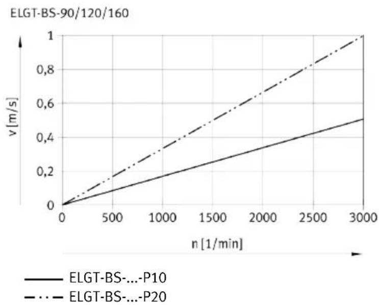
10.3 Characteristic speed curves
Velocity v as a function of the rotational speed n.
i
Rotational speed n and speed v are stroke-dependent. Observe max. Permissible rotational speed n as a function of working stroke l.
line
| n [1/min] | ELGT-BS-...P10 | ELGT-BS-...P20 | | --------- | -------------- | -------------- | | 0 | 0.0 | 0.0 | | 500 | ~0.1 | ~0.2 | | 1000 | ~0.2 | ~0.4 | | 1500 | ~0.3 | ~0.6 | | 2000 | ~0.4 | ~0.8 | | 2500 | ~0.5 | ~1.0 | | 3000 | ~0.6 | ~1.2 |Fig. 8: Velocity v as a function of the rotational speed n.
Max. permissible rotational speed n as a function of working stroke l.

line
| l [mm] | ELGT-BS-90-P10 | ELGT-BS-90-P20 | | ------ | -------------- | -------------- | | 0 | 3000 | 3000 | | 600 | 3000 | 3000 | | 800 | 2500 | 2200 | | 1000 | 1500 | 1400 |Fig. 9: ELGT-BS-90, rotational speed n as a function of working stroke l
Technical data

line
| l [mm] | ELGT-BS-120-P10 | ELGT-BS-120-P20 | | ------ | --------------- | --------------- | | 0 | 3000 | 3000 | | 200 | 3000 | 3000 | | 400 | 3000 | 3000 | | 600 | 3000 | 3000 | | 800 | 2500 | 2250 | | 1000 | 1500 | 1500 |Fig. 10: ELGT-BS-120, rotational speed n as a function of working stroke l

line
| l [mm] | ELGT-BS-120-P10 | ELGT-BS-120-P20 | | ------ | --------------- | --------------- | | 0 | 3000 | 3000 | | 200 | 3000 | 3000 | | 400 | 3000 | 3000 | | 600 | 3000 | 3000 | | 800 | 3000 | 3000 | | 1000 | 2000 | 2000 |Fig. 11: ELGT-BS-160, rotational speed n as a function of working stroke l
Copyright:
Festo SE & Co. KG
Ruiter Straße 82
73734 Esslingen
Germany
Phone:
+49 711 347-0