P.BE-CP-CO-IT - Unspecified Festo - Free user manual and instructions
Find the device manual for free P.BE-CP-CO-IT Festo in PDF.

User questions about P.BE-CP-CO-IT Festo
0 question about this device. Answer the ones you know or ask your own.
Ask a new question about this device
Download the instructions for your Unspecified in PDF format for free! Find your manual P.BE-CP-CO-IT - Festo and take your electronic device back in hand. On this page are published all the documents necessary for the use of your device. P.BE-CP-CO-IT by Festo.
USER MANUAL P.BE-CP-CO-IT Festo
natural_image
Black-and-white photo of industrial battery modules with no visible text or symbolsFESTO
Description Electronic
CPVvalveterminal withdirectlink
TypeCPV-GE-CO-8
Fieldbusprotocol - CANopen

natural_image
Isometric line drawing of a mechanical or electrical component with no visible text or symbolsDescription 175580 en0009b
Contentsandgeneralinstructions
Author H.-J.Drung, H.Hohner....
EditorsH.-J.Drung, M.Holder.
Originalde.
TranslationtranslineDeutschlandGmbH.
Layout ...... Festo SE & Co. KG, Abtl. KG-GD
...TypesettingDUCOM
Edition ...... en 0009b
Title ...... MANUAL-EN
Designation P.BE-CP-CO-EN
Order no. 175 580
© (Festo SE & Co. KG, D-73726 Esslingen, Federal Republic of Germany 2000)
Internet: http://www.festo.com
E-Mail: service_international@festo.com
The copying, distribution and utilization of this document as well as the communication of its contents to others without expressed authorization is prohibited. Offenders will be held liable for the payment of damages. All rights reserved, in particular the right to carry out patent, utility model or ornamental design registration.
Contentsandgeneralinstructions
Contents
DesignateduseV.
TargetgroupV.
Service V
InformationonthismanualInformationonthismanualVI. . . . . . . . . . . . . . . . . . . .
Important user instructions VII
1. Installation 1-1
1.1 General instructions on installation 1-3
1.2 Configuring the CPV valve terminal 1-4
1.2.1 Opening and closing the switch cover 1-5
1.2.2 Setting the CPV valve terminal 1-5
1.3 Connecting the CPV valve terminal 1-9
1.3.1 Connecting cable 1-9
1.3.2 Preparing the connecting cables 1-10
1.3.3 Selecting the power unit 1-12
1.3.4 Connecting the load voltage for the CPV valves 1-13
1.4 Connecting to the field bus 1-17
1.4.1 Installing the terminating resistor 1-22
2. Commissioning 2-1
2.1 Commissioning a CANopen master 2-3
2.1.1 Number of outputs 2-3
2.1.2 General information on CANopen 2-4
2.2 Summaries 2-5
2.2.1 Brief summary of the scope of functions 2-5
2.2.2 Summary of the object directory 2-6
2.2.3 COB identifierCOB identifier 2-7
2.2.4 Start-up reaction of the CPV valve terminal 2-8
2.2.5 Default identifier distribution 2-10
2.3 Summary of the object directory 2-11
2.3.1 PDO communication parameter record 2-12
2.3.2 PDO communication mapping parameter 2-13
2.3.3Digitaloutputs2-14.
2.3.4Reactionofthedigitaloutputstoafault2-15.....
2.4 Structure of emergency object 2-17.
2.5 Basic rules for addressing 2-18
2.5.1 Addressing the CPV valve terminal 2-19
2.6 Examples: communication run 2-20
3.1 Summary of diagnostic possibilities 3-3
3.2 Diagnosis via LEDs 3-4
3.2.1 Normal operating status 3-4
3.2.2 Error display 3-5
3.2.3 LED for the switching status of the valve solenoid coil 3-6
3.3 Testing the valves 3-7
3.3.1 Starting the test routine 3-8
3.3.2 Stopping the test routine 3-8
3.4 Diagnosis via the field bus 3-9
3.5 Error treatment 3-10
3.5.1 Reaction to faults in the control system 3-10
3. Diagnosis 3-1
A. Technical Appendix ...... A-1
A.1 Technical specifications of the valve terminal with CANopen direct link ... A-3
A.2 Accessories A-5
B.1 Index B-3
B. Index B-1
Designateduse
TheCPVvalveterminalwithdirectlinktotheCANopendocumentedinthismanualisdesignatedexclusivelyforuseas aslaveontheCANopen.TheFestoCPVvalveterminalmay onlybeusedasfollows:
- a s d e s i g n a t e d
-inoriginalcondition
-withoutunauthorizedmodifications
-infaultlesstechnicalcondition.
Thespecifiedlimitvaluesforpressures,temperatures,electricaldata,moments,etc.mustbeobservedwhenadditionalcommercially-availablecomponentssuchassensorsand actuatorsareconnected.
Pleasecomplyalsowithnationalandlocalsafetylawsand regulations.

Warning
Ifusedasanexplosion-protectedoperatingmedia, donot disconnectwhenundertension!
Targetgroup
Thismanualisdirectedexclusivelyattechnicianswhoare trainedincontrolandautomationtechnologyandwhohave experienceininstalling,commissioning,programmingand diagnosingnetworkmodulesontheCANopen.
Service
Please consult your local Festorepair service if you have any technical problems.
InformationonthismanualInformationonthismanual

Pleasenote
This manual describes the function of the CPV valveter- minal with CANopendirect link with
-softwareversion1.2
–hardwarestatusasfrom0198.
This manual contains specific information on the installation, commissioning, programming and diagnosis of the CPV valve terminal with direct link to the CANopen.

Informationonthepneumaticmodulescanbefoundinthe "Pneumaticsmanual,P.BE-CPV-...".
Importantuserinstructions
Dangercategories
This manual contains instructions on the possible dangers which may occur if the product is not used correctly. These instructions are remarked (Warning, Caution, etc), printed on a shaded background and marked additionally with a pictogram. Adistinctionism made between the following danger warnings:

Warning
...Thismeansthatfailuretoobservethisinstructionmay resultinseriouspersonalinjuryordamagetoproperty.

Caution
...Thismeansthatfailuretoobservethisinstructionmay resultinpersonalinjuryordamagetoproperty.

Pleasenote
...Thismeansthatfailuretoobservethisinstructionmay resultindamagetoproperty.

The following pictogram markspassages in the text which describe activities with the electrostatically sensitive components.
Electrostaticallysensitivecomponentsmaybedamaged if theyarenothandledcorrectly.
Markingspecialinformation
The following pictograms mark passages in the text containings special information.
Pictograms
Information:
Recommendations, tips and reference to other information sources.
Accessories:
Informationonnecessaryorsensibleaccessoriesforthe Festoproduct.
Environment:
Informationonenvironment-friendlyuseofFestoproducts.
Textmarkings
- Thebulletindicatesactiviteswhichmaybecarriedoutin anyorder.
- Figuresdenoteactivitieswhichmustbecarriedoutinthe numericalorderspecified.
-Hyphensindicategeneralactivities.

text_image
i ..Installation
Chapter1
- Installation
Contents
1.Installation1-1....
1.1 Generalinstructionsoninstallation1-3.
1.2ConfiguringtheCPVvalveterminal1-4.....
1.2.1 Opening and closing the switch cover 1-5
1.2.2 Setting the CPV valve terminal 1-5
1.3 Connecting the CPV valve terminal 1-9
1.3.1 Connecting cable 1-9
1.3.2 Preparing the connecting cables 1-10
1.3.3 Selecting the power unit 1-12
1.3.4 Connecting the load voltage for the CPV valves 1-13
1.4 Connecting to the field bus 1-17
1.4.1 Installing the terminating resistor 1-22
1. Installation
1.1 Generalinstructionsoninstallation

Warning
Switchoffthefollowingbeforeundertakinginstallation and/ormaintenancework:
• thecompressedairsupply
•theoperatingvoltagesupplyforthelogic
•theoperatingvoltagesupplyforthevalves
Youcantherebyavoid:
-uncontrolled movementsofloosetubing
—undesiredmovementsoftheconnectedactuators
-undefinedswitchingstatesoftheelectroniccomponents.

Caution
The CPV valveterminal contain selectrostatically vulnerable components.
- Donotthereforetouchanycomponents.
- Observetheregulationsforhandlingelectrostatically vulnerablecomponents.
Youcantherebypreventdamagetotheelectroniccomponents.
1. Installation
1.2ConfiguringtheCPVvalveterminal
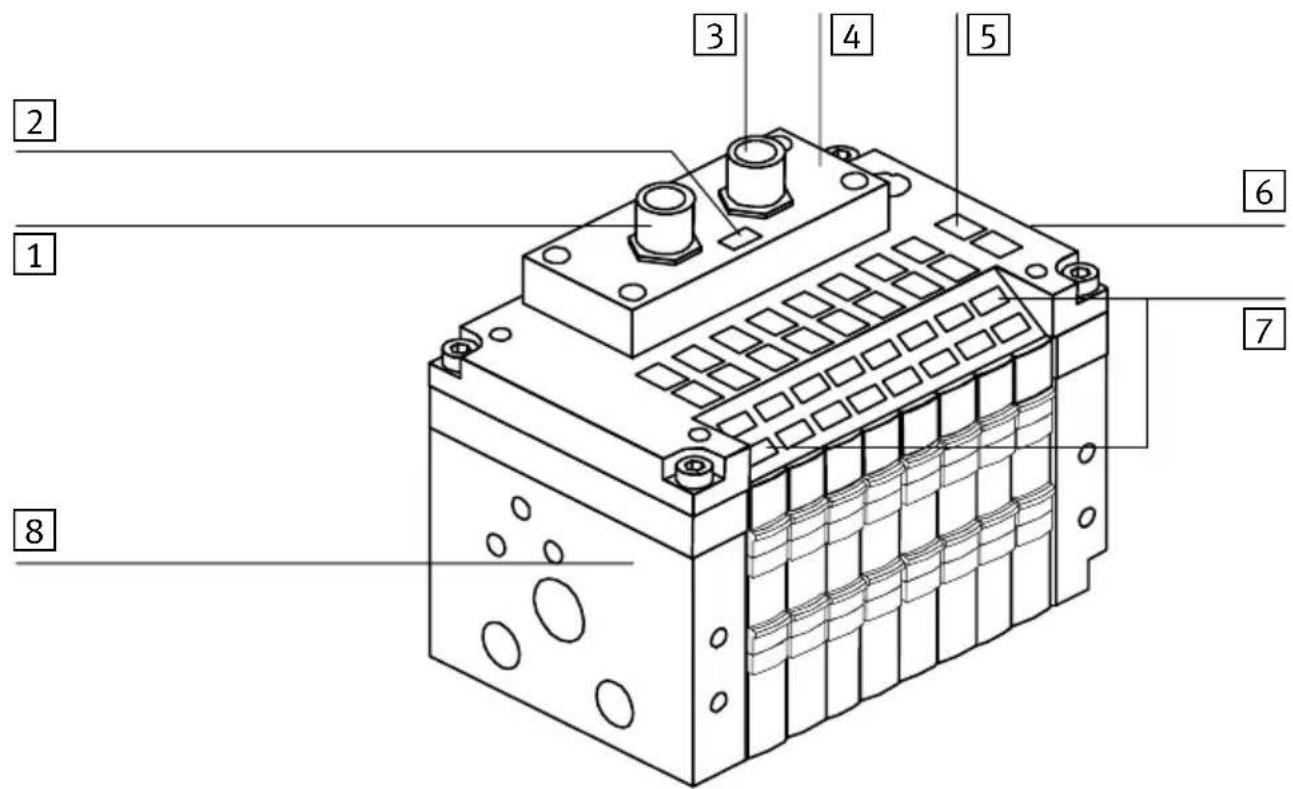
The following connecting and display elements can be found on the CPVvalveterminal with CANopendirect connection:
text_image
Technical diagram of an electrical contactor with numbered components labeled 1 through 81 LoadvoltageconnectionforCPVVvalves
2 Error/statusLED
3 Fieldbusconnection
4 Switchcoveronthesub-base
Fig.1/1: Connectinganddisplayelements
5 Indentificationlabels
6 Earthing/groundconnection
7 Singalstatusdisplayofpilotsolenoids
8Typeplate
- Installation
1.2.1 Opening and closing the switch cover
- Opening Unscrewandremovethe4screwsintheswitch cover.Pullthecoverupwards.
- Closing Replacethecover.Insertandtightenthe4screwsin diagonallyoppositesequence.
1.2.2 Setting the CPV valveterminal
The following setting possibilities can be found in the CPV valveterminal together with an LED for displaying any faults as well as the status:
- the station number ( C
-thefieldbusbaudrate
1 Addressselector switch (station-number)
2 DIL-switchfor baudrate

text_image
1 2 12 12 12 12 12 12 12 14 14 14 14 14 14Fig.1/2: Settingelements
1. Installation
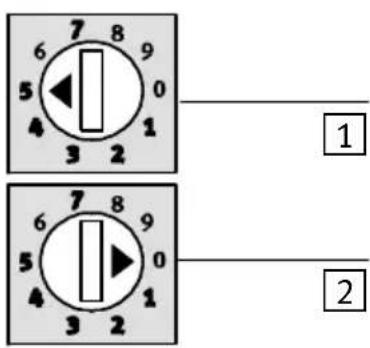
1 Addressselector switchforUNITS figure
2 Addressselector switchforTENS figure

text_image
1 2Fig.1/3:Addressselectorswitches

Pleasenote
StationnumbersmayonlybeassignedonceperCANopen interface.

Recommendation
Assignthestationnumbersinascendingorder.Ifnecessary, takeintoaccountthemachinestructureofyoursystemwhen assigningthenumbers.
1. Installation

The following station numbers are permitted: 1;...;98
Warning
Youmustobserveanypossiblelimitationsimposedbythe CANopenmasterinrespectofthestationnumbers.
Proceedasfollows:
1.Switchoftheoperatingvoltage.
2. AssignnanunassignedstationnumbertotheCPVvalve terminal.
3. Useascrewdrivertosetthearrowsoftheaddressselectorswitchestotheunitsortensfigureofthedestationnumber.
text_image
7 8 9 6 5 0 4 1 3 2 1 2Settingfor fieldbusaddress:05
text_image
7 8 9 6 5 0 4 1 3 2 1 2 7 8 9 6 5 0 4 1 3 2Settingfor fieldbusadresse:38
1 UNITS
2 TENS
1 UNITS
2 TENS
Fig.1/4:Examplesofaddresssettings
- Installation
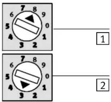
Settingthefieldbusbaudrate

Warning
SetthefieldbusbaudrateoftheCPVvalveterminalso thatitisthesameasthebaudrateonthemasterinterface.
bar
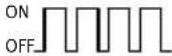
Fieldbusbaudrate | Fieldbusbaudrate | 20kBaud125kBaud | 500kBaud1000kBaud | 1000kBaud | | :--- | :--- | :--- | :--- | | ON 1 | ON 1 | ON 1 | ON 1 | | ON 2 | ON 2 | ON 2 | ON 2 | The diagram shows four rectangular blocks representing the same block type in a grid layout. The top row contains 'Fieldbusbaudrate' labels, while the bottom row contains three rows labeled 'ON'.Fig.1/5: Setting the field bus baud rate
1. Installation
1.3 Connecting the CPV valveterminal
1.3.1 Connectingcable
FieldbuscableUseatwistedscreened4-corecableforthefieldbus.Thebus
interface and the internal logic of the CPV valvete supplied with powerviathefieldbuscable.

Warning
- YoumustrefertothePLCmanualortheusermanualfor yourbusinterfaceforinstructionsregardingthechoice ofcable.Alsotakeintoaccountthedistanceandthe baudrateselected.
- Selectalsotheappropriatecablecrosssections.
- Notealsothedropinvoltage:
- in the supply line for the bus interface and
- of the internal logic of the CPV valveterminal.
BuslengthThetablebelowshowstheguidevaluesforthemaximumbus
cablelengthdependingonthebaudrateselected.Exactdetailscanbefoundinthemanualsforyourcontrolsystemor bus interface.
| Baudrate | Maximum bus length | Maximum branch line length |
| 1000kBaud | 10-40m | 0.3m |
| 500kBaud | 50-100m | 0.75m |
| 125kBaud | 500m | 3 m |
| 20kBaud | 1000m | 7.5m |
1. Installation
Load voltage cable
- Use an load voltage cable with sufficient cross section.
- AvoidlongdistancesbetweenthepowerunitandtheCPV terminal. Longloadvoltagecablesreducethevoltagesuppliedby thepowerunit.
- If necessary, calculate the suitable cable cross section and the maximum permitted cable length.
1.3.2 Preparing the connecting cables
The connection so the fieldbus interface and those for the load voltage are in the form of plugs. The pin assignment of the fieldbus interface and that of the load voltage connection are shown on the following pages.
Inordertoconnecttheloadvoltage, useplugsfromtheFesto rangewhichcorrespondtotheouterdiameterofthecables used(seeAppendixA,Accessories).
loadvoltage connection
Ready-to-usecableswithplugsforthefieldbusconnection areavailablefromvariousmanufacturers(seeAppendixA, Accessories).
FieldbusplugsWhenyouhaveselectedsuitablecables,connectthemas follows:
- Installation
1 Cable
2 Housing
3 Connectingpart
4 Strainrelief
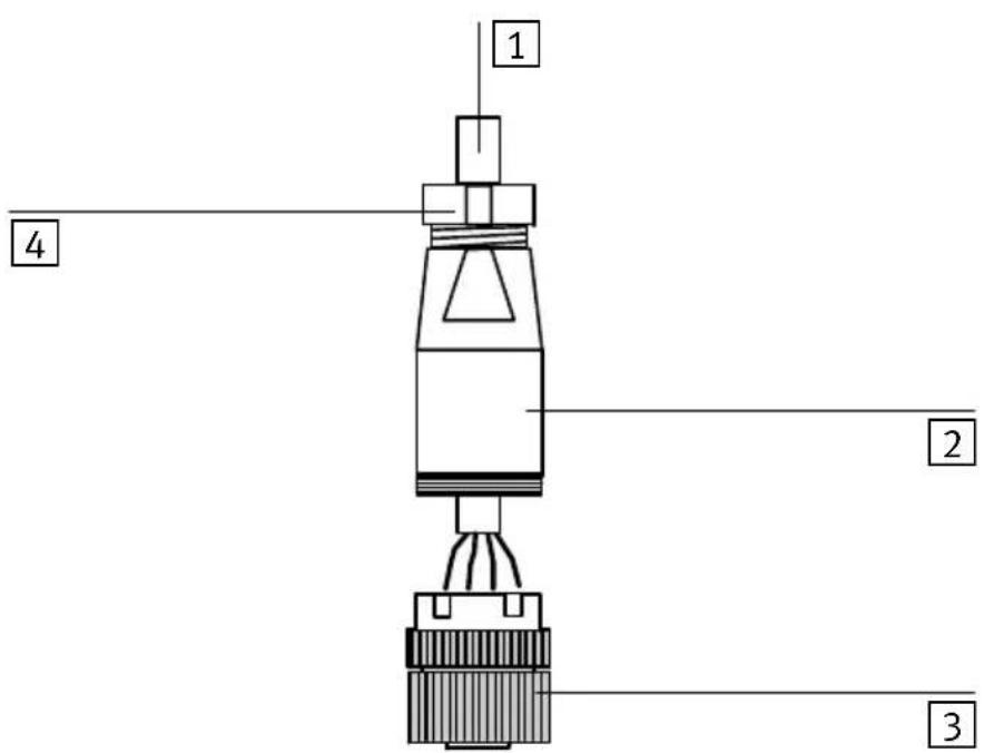
text_image
1 2 3 4Fig.1/6:Preparingtheconnectingcable
Preparingthecables
- Loosenthecentreknurlednuttoopenthesocket.
- Open the strain relief on therear of the housing. Then passthe cable through as described below.
- Remove 5 mm of the insulation from the cable and fit ends sleeve to the wirestrands.
- Connect the end so fthe conductors.
- Replacetheconnectingpartonthehousingofthesocket. Pullthecablebacksothatitisnotloopedinsidethe housing.
- Tightenthestrainrelief.
1.3.3 Selecting the power unit

Warning
Useonlypowerunitswhichguaranteeereliableelectrical isolationoftheoperatingvoltagesinaccordancewithIEC 742/EN60742/VDE0551withatleast4kVisolation resistance.Switchpowerpacksarepermitted,providing theyguaranteeereliableelectricalisolationasper EN60950/VDE0805.
The current consumption of a CPV valveterinal dependence then number of valvecoils.
- Alwaysuseclosed-loopcontrolledpowerunits.
- Whenselecting the power unit, check that it provides enough power. Include in your calculation the complete current requirements as shown in the following table.
- Connect the operating voltage for the CPV valve coils, the EMERGENCY STOP circuit.
Completecurrentconsumptionet
ThetablebelowshowshowtocalcullatethecompletecurrentconsumptionforaCPVvalveterminal.Thevaluesspecifiedhavebeenroundedup.
| CurrentconsumptionofbusinterfaceandlogicSums | ||
| CPVvalveterminal50mA | 1) | |
| Currentconsumptionofvalvesupply | ||
| Currentconsumptionofallvalve coilssuppliedsimultaneouslywith powe 1) | _x__mA=___mA | |
| 1) Currentconsumptiondependsonvalvetype (seetechnicalspecificationsofthevalves) | ||
- Installation
1.3.4 Connecting the load voltage for the CPV valves

Caution
ProtecttheloadvoltagecircuitfortheCPVvalvecoilswith anexternalfusemax.2A.
Withtheexternalfuseyoucanavoidfunctionaldamageto theCPVvalveterminalintheeventofashortcircuit.
Theloadvoltageissuppliedviathe4-pinM12plugonthe CPVvalveterminal.
1 Loadvoltage connection
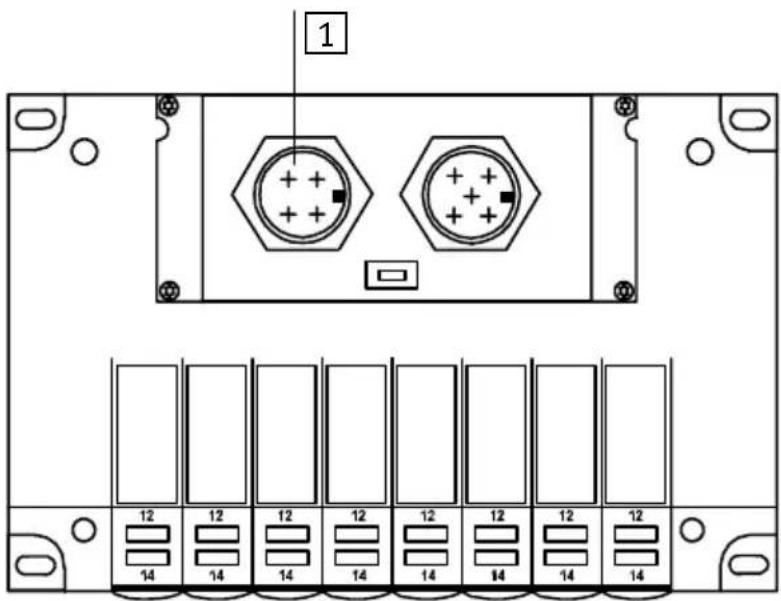
text_image
1 12 12 12 12 12 12 12 12 12 14 14 14 14 14 14 14 14Fig.1/7:Connectionforthe24VDCloadvoltage
The current consumption depends on the type of valve coil. Pleaserefertothe "Pneumaticsmanual, P.BE-CPV--" for the values.
1. Installation

Recommendation:
- ConnecttheloadvoltagefortheCPVvalves(pin2)viathe EMERGENCYSTOPcircuit.
- Checkthe24Vloadvoltagewhilethesystemisoperating.Makesurethattheloadvoltagestilllieswithinthe permittedtolerancesevenduringfulloperation.
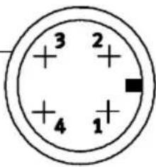
Pinassignmentoftheloadvoltageconnectionfor theCPVvalves
1
chemical
Atomic structure diagram of a nuclear charge carrier with four protons and one electron shell1 Pinassignment
1:n.c.(notconnected)
2:24VDCloadvoltageforCPVvalves
3:0VloadvoltageforCPVvalves
4:n.c.(notconnected)
Fig.1/8: Pinassignmentofloadvoltageconnection
1. Installation
EarthconnectionTheCPVvalveterminalhasanearthconnectionontheend plate.

Pleasenote
- Connecttheearthconnectionoftheendplatewithlow impedance(shortcablewithlargediameter).

You will thereby avoid interference caused by electromagnetic influences.
Remark:
Protectionagainstelectricshock(protectionagainstdirect andindirectcontact)isguaranteedonFestovalveterminals bytheuseofPELVpowerunitsinaccordancewithEN 60204-1/IEC204.Thevalveterminalsmustbeearthedin ordertoensuretheirfunction(e.g.EMC).
1. Installation
ConnectionexamplePleaseobservethefollowingwhenconnectingthe24Vsupply(pin2):
- Maintainthetoleranceof24VDC+10/-15%.
- Useacableofsufficientcrosssectionwhenconnecting theearthcabletotheCPVvalveterminal.
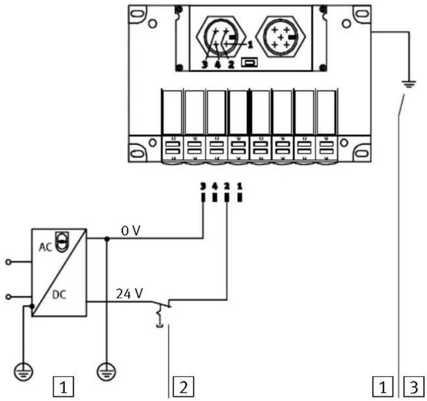
text_image
AC DC 0 V 24 V 1 2 3 4 5 6 7 8 9 10 11 12 13 14 15 16 17 18 19 20 21 22 23 24 1 2 31 Potentialcompensation
2 The24Vloadvoltagesupplyforthevalvescanbe switched offseparately.Thebusinterfaceandtheinternallogic aresuppliedwithpowerviathefieldbusconnection
3 Connectionforearth/groundontheendplate
Fig.1/9:Example-connectingthe24Vsupplyandearth cable
1. Installation
1.4 Connectingtothefieldbus
There is a field bus plug on the CPV val v terminal f necting it to the field bus. The following must be connected to this plug:
- t h e t w o b u s c a b l e s
-thevoltagesupply(+24VDCund0V)forthebusinterfaceandtheinternallogic
-thecablescreening/shield.
ThehardwarebasisofthebusinterfaceistheCANbus.A typicalfeatureofthisbusisthatthebusinterfaceissupplied withvoltageviathefieldbusplug.
Fieldbussocket
The bus connectionism made via a branch line with M12 socket with a PG9 screw connector. These can be obtained from Festo (type FBSD-GD-9-5POL, partno.18324).

Alternativelyyoucanusetheready-to-usebuscablessuppliedbyvariousmanufacturers(seealsoAppendixA,Accessories).

Pleasenote
RefertoyourPLCmanualorbusinterfacemanualtoascertainwhichT-adapterandmaximumbranchlinelengthare permittedforyourcontroller.
1. Installation
Basicstructureofthebusinterface

text_image
1 2 3 4 5 6 7 8 + 24 V 0 V1 Fieldbus
2 Voltagesupply
3 Screening/shield
4 Branchline
5 T-adapter
6Bus
7 Microprocessor
8 Valvedriver
Fig.1/10: Basic structure of the bus interface
1. Installation
BussupplyAvoidlongdistancesbetweenthebusinterfacesupplyand thelogicsupplyandtheCPVvalveterminal.

Pleasenote
Thetolerancesinrespectoftheinterfacesupplyonbus slavesvariesaccordingtothemanufacturer.Youmusttake thisintoaccountwhenplanningthebuslengthandplacing thepowerunit.

Recommendation
Placethepowerunitapproximatelyinthecentreofthebus.
The following tolerance in the bus interfaces supply appliesto the Festo CPV valveterinals:
$$ V _ {\max} = 2 5. 0 \mathrm{V} $$
$$ V _ {\min} = 1 1. 5 \mathrm{V} $$
1. Installation
Pinassignmentofthefield businterface
Connectthefieldbuscablecorrectlytotheterminalsofthe buscablesocket.Observealsotheconnectioninstructions belowaswellastheinformationinthemanualforyou trollerorbusinterface.

Caution
- Makesureofthecorrectpolaritywhenyouconnectthe fieldbusinterfaceandthevoltagesupplyforthebus interface/internallogic.
- Connectthescreening/shield.

text_image
3 2 + 5 + 4 1 1 3 220nF 1MΩ 21 Pinassignment 1: Schirm(CAN_SHLD) 2: DC+24Vbusinterface/logic(CAN_V+) 3: 0Vbusinterface/logic(CAN_GND) 4: Data+(CAN_H) 5: Data-(CAN_L)
2 Nodehousing(PE)
3 Internalscreening/shieldconnectionintheCPVvalve terminal
Fig.1/11:InternalRCnetwork
1. Installation
ThediagrambelowshowstheconnectionoftheCPVvalve terminaltoaCANopenmasterwithabusinterfaceinaccordancewithDS102.
| PLC/PC/IPCpinassignmentPlugPinPin | Valveterminalpinassignmentoffieldbusinterface | |||
 | 1 | n.c. | ||
| 2 | CAN_L | —— Data-/CAN_L | 5 | |
| 3 | CAN_GND | —— GNDBus | 3 | |
| 4 | n.c. | |||
| 5 | CAN_SHLD | —— Screening/shield | 1 | |
| 6 | GND | |||
| 7 | CAN_H | —— Data+/CAN_H | 4 | |
| 8 | n.c. | |||
| 9 | CAN_V+ | —— 24VBus | 2 | |
| nc=notconnected | ||||
Fig.1/12: PinassignmentasperDS102
1. Installation
1.4.1 Installingtheterminatingresistor
If the CPV valveterminaltobe connected dissituated at the endofthefieldbus, aiterminating resistor (120 Ohm, 0.25 Watt) must be fitted in the fieldbus socket.
If you are using T-adapters, were recommend that you fit the terminating resistortotheunusedoutputoftheT-adapter.
TerminatingresistorCrimpthewiresoftheresistortogetherwiththoseofthefield buscablebetweenhecoresData+(pin4)andData-(pin5) ofthebuscablesocket.

Pleasenote
Inordertoguaranteereliablecontact, were recommend that the wires of the resistor and those of the buscable be crimped together in common connectors sleeves.

text_image
1 120Ω 4 5 2 11 Terminatingresistor120Ohm,0.25W
Fig.1/13:Installingtheterminatingresistor
Commissioning
Chapter2
Contents
2. Commissioning2-1....
2.1 CommissioningaCANopenmaster2-3.....
2.1.1 Numberofoutputs2-3.....
2.1.2 General information on CANopen 2-4
2.2 Summaries 2-5
2.2.1 Brief summary of the scope of functions 2-5
2.2.2 Summary of the object directory 2-6
2.2.3 COB identifierCOB identifier 2-7
2.2.4 Start-up reaction of the CPV valve terminal 2-8
2.2.5 Default identifier distribution 2-10
2.3 Summary of the object directory 2-11
2.3.1 PDO communication parameter record 2-12
2.3.2 PDO communication mapping parameter 2-13
2.3.3 Digital outputs 2-14
2.3.4 Reaction of the digital outputs to a fault 2-15
2.4 Structure of emergency object 2-17
2.5 Basic rules for addressing 2-18
2.5.1 Addressing the CPV valve terminal 2-19
2.6 Examples: communication run 2-20
2. Commissioning
2.1 CommissioningaCANopenmaster
Thischapterdealswiththeconfigurationandaddressingofa CPVvalveterminalonaCANopeninterfaceorCANopen master.
The followingstandardshavebeentakenintoaccount:
| Followingstandards | |
| DS 301 | Draft Standard 301 is based on the CAL communication profile |
| DSP 401 | Draft Standard Propsal 401 defines the device profiles forinputandoutputmoduleswithinCANopen |
| DS201Ds207 | CANApplicationLayerCAL |
Inordertounderstandthischapteryoushouldbefamiliar withCANopenaswellasthespecificationsDS301andDSP 401.
2.1.1 Numberofoutputs

Pleasenote
Thesumoftheoutputsisalways2bytes,irrespectiveoftheextentandoftheequipmentfittedontheCPV valveterminal.
2. Commissioning
2.1.2 GeneralinformationonCANopen
CANopendeviceshaveanobjectdirectorywhichprovides accessinastandardformtoallimportantslaveparameters. ACANopensystemisconfiguredprincipallybyaccesstothe objectdirectoryoftheindividualslaves.Theaccessmechanismisprovidedbyservicedataobjects(SDOs).
There are twodifferentcommunicationmechanismsforcommunicationinaCANopensystem.
The Process Data Objects (PDOs) provide the fast transfer of processingdataandaretransmittedbysimpleCANmessageswithoutprotocoloverhead.Processdataobjectscanbe transmittedevent-controlled,synchronoustoasystemtime sequenceorondemand.
The Service Data Objects (SDOs) form a point-to-point connection and permit access to every entry in the object directory of anode.
2. Commissioning
2.2 Summaries
2.2.1 Brief summary of the scope of functions
-Modulestatesandboot-upaspercommunicationprofile DS301
-Allentriesinthecommunicationpartoftheobjectdirectoryareincluded
- Aservicedataobjectforreadandwriteaccesstotheobjectdirectory
-Aprocessdataobjectforaccesstodigitaloutputs
-PDO-COBidentifierforwriteaccessnotvariable
-PDOtransmissiontypeforwriteaccessfirmlyimplementedasasynchronous(255)
-PDOemergencytelegramforerrormessagestothe master
-Nodeguarding
-DefaultsettingofallidentifiersasperDS301andthe nodeaddress
2. Commissioning
2.2.2 Summaryoftheobjectdirectory
The followingtableshowstheimplementedobjectsofthe FestoCPVvalveterminal.Thetableisbasedonstandard DS-301.
| Index(hex) | Objecte |
| 1000-100ECommunicationpartoftheobjectdirectories | |
| 1400CommunicationparametersforreceivePDO | |
| 1600MappingparametersforreceivePDO(variablemappingnotimplemented) | |
| 6200Outputarray | |
| 6206Faultmodearrayfortheoutputlines | |
| 6207Faultstatearrayfortheoutputlines | |
2.Commissioning
2.2.3COBidentifierCOBidentifier
The FestoCPVvalveterminalwithCANopenisa"minimum capabilitydevice"(minimumdevice).ThePDO-COBidentifier canbeselectedindividuallyforwriteaccess.
Bit10Bit7Bit6Bit0
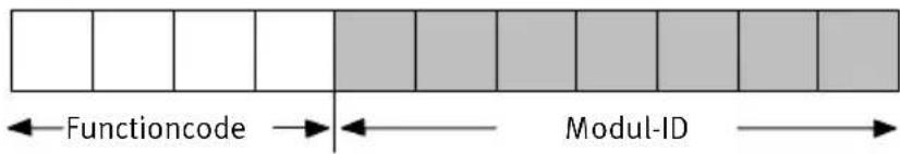
text_image
Functioncode Modul-IDFig.2/1: StructureofCOBidentifier
Maximum127slavescanbeaddressedwiththemoduleID. Theaddressisalsoreferredtoasthestationnumber,MAC-ID orMESSAGE-ID.Bymeansoftheaddresss selectorswitchesof theCPVvalveterminalyoucansetaddressesfrom1...98.
-Address99isreservedfortheselftest.
- Address 00 is not valid.
Example
COB-IDforCPVvalveterminal.Setaddress(rotaryswitch): 10D.
Bit10Bit7Bit6Bit0

text_image
0 0 0 1 0 1 0 Functioncode Modul-IDFig.2/2: StructureofCOBidentifierforvalveterminalno.10
2. Commissioning
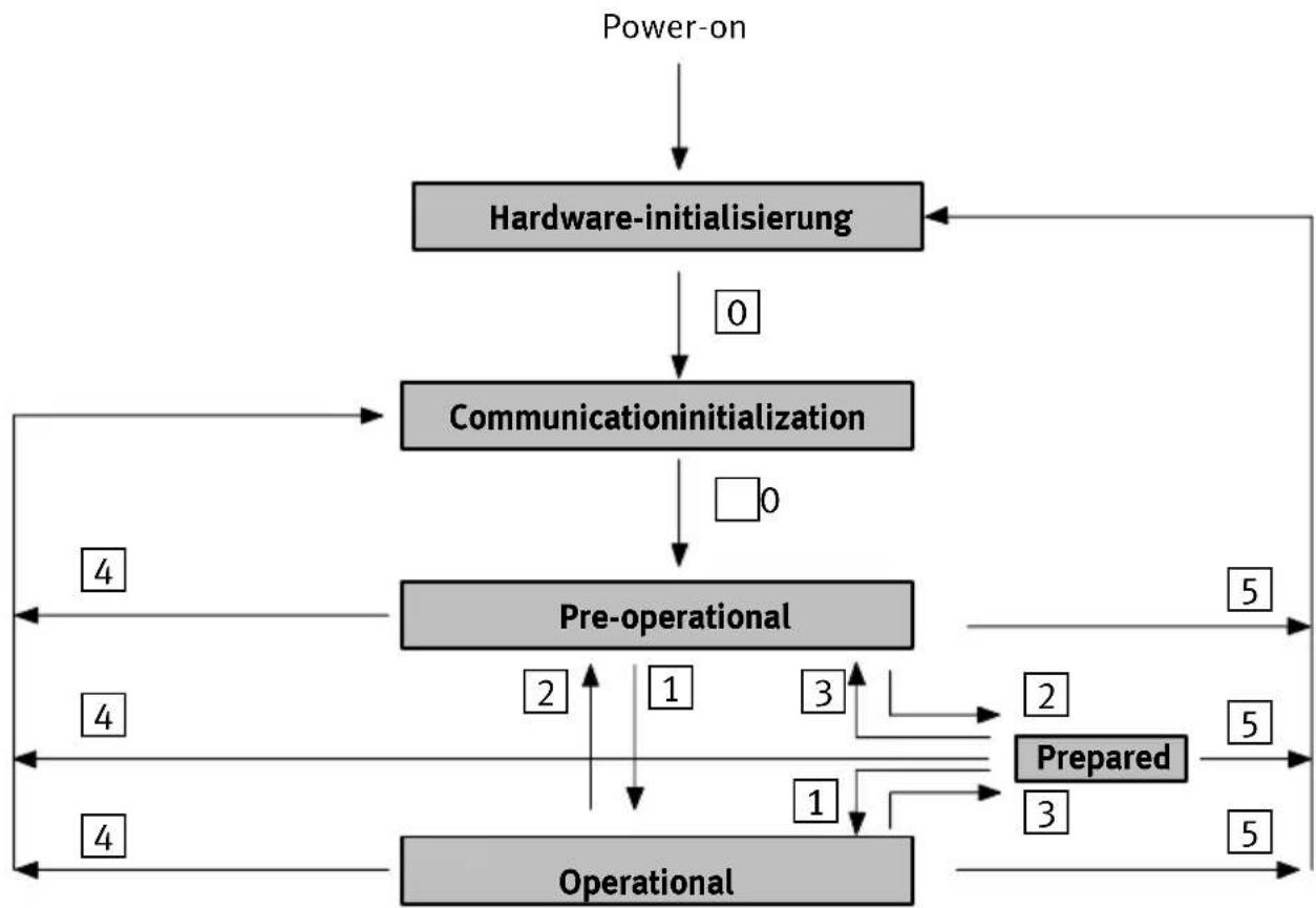
2.2.4 Start-up reaction of the CPV valveterminal
ThediagrambelowshowsthestatusdiagramoftheFesto CPVvalveterminal.
flowchart
graph TD
    A["Power-on"] --> B["Hardware-initialisierung"]
    B --> C["Communicationinitialization"]
    C --> D["Pre-operational"]
    D --> E["Operational"]
    E --> F["Prepared"]
    F --> G["Operational"]
    G --> H["Operational"]
    H --> I["Operational"]
    I --> J["Operational"]
    J --> K["Operational"]
    K --> L["Operational"]
    L --> M["Operational"]
    M --> N["Operational"]
    N --> O["Operational"]
    O --> P["Operational"]
    P --> Q["Operational"]
    Q --> R["Operational"]
    R --> S["Operational"]
    S --> T["Operational"]
    T --> U["Operational"]
    U --> V["Operational"]
    V --> W["Operational"]
    W --> X["Operational"]
    X --> Y["Operational"]
    Y --> Z["Operational"]
    Z --> AA["Operational"]
    AA --> AB["Operational"]
    AB --> AC["Operational"]
    AC --> AD["Operational"]
    AD --> AE["Operational"]
    AE --> AF["Operational"]
    AF --> AG["Operational"]
    AG --> AH["Operational"]
    AH --> AI["Operational"]
    AI --> AJ["Operational"]
    AJ --> AK["Operational"]
    AK --> AL["Operational"]
    AL --> AM["Operational"]
    AM --> AN["Operational"]
    AN --> AO["Operational"]
    AO --> AP["Operational"]
    AP --> AQ["Operational"]
    AQ --> AR["Operational"]
    AR --> AS["Operational"]
    AS --> AT["Operational"]
    AT --> AU["Operational"]
    AU --> AV["Operational"]
    AV --> AW["Operational"]
    AW --> AX["Operational"]
    AX --> AY["Operational"]
    AY --> AZ["Operational"]
    AZ --> BA["Operational"]
    BA --> BB["Operational"]
    BB --> BC["Operational"]
    BC --> BD["Operational"]
    BD --> BE["Operational"]
    BE --> BF["Operational"]
    BF --> BG["Operational"]
    BG --> BH["Operational"]
    BH --> BI["Operational"]
    BI --> BJ["Operational"]
    BJ --> BK["Operational"]
    BK --> BL["Operational"]
    BL --> BM["Operational"]
    BM --> BN["Operational"]
    BN --> BO["Operational"]
    BO --> BP["Operational"]
    BP --> BQ["Operational"]
    BQ --> BR["Operational"]
    BR --> BS["Operational"]
    BS --> BT["Operational"]
    BT --> BU["Operational"]
    BU --> BV["Operational"]
    BV --> BW["Operational"]
Fig.2/3:StatusdiagramoftheCPVvalveterminal
Descriptionofthestatustransitions
| Status transition | DesignationCommand specifier(cs) | Function | |
| 0 | Autom.BootupnachPowerOn | ||
| 1 | Start_Remote_Node_Indication | 01_H | StartstheCPVvalveterminal (operationalmode), SDOtransmissionvalid-PDOtransmissionvalid (outputsactive)-Nodeguardingvalid (response:toggle+05 H) |
| 2 | Enter_Pre_Opera-tion_State_Indication | 80_H | CPVvalveterminalinpre-operational mode: SDOtransmissionvalid-PDOtransmissionnotvalid(out-putsassumeerrorstatus*)-Nodeguardingvalid (response:toggle+7F H) |
| 3 | Stop_Node_Indication | 02_H | Stopp communication:-SDOtransmissionnotvalid-PDOtransmissionnotvalid (outputsassumeerrorstatus*)-Nodeguardingvalid(response: toggle+04 H) |
| 4 | Reset_Communication_Indication | 82_H | Resetsthecommunicationfunctions:-Outputsarereset-Maskingoftheoutputsresetto default |
| 5 | Reset_Node_Indication | 81_H | Moduleresetincl.application:-Outputsarereset-SDOre-initialized, modifiedvaluesarereset |
| *)Onlyaftertransferfromoperationalmodetopreparedorpre-operationalmode | |||
2.2.5 Defaultidentifierdistribution
The followingtableshowstheidentifierdistribution.
| Peer-to-peer objects | ||||
| ObjectnameObject | designation | Functioncode (binary) | CMSpriority group | Valuerangeof COBidentifier withFestoCPV valveterminals |
| EMERGENCYForhigh-priority processese.g.un-dervoltage | 00010,1129 | D ...226 D 081H... 0E2H | ||
| Recive-PDO01002513 | D ... 610D 201H 262H | |||
| Send-SDO | 101161409 | D ... 1506D 581H 5E2H | ||
| Recive-SDO | 11006,7 | 1537 | D ... 1634D 601H 662H | |
| Nodeguarding | 111071793 | D ... 1890D 701H 762H | ||
2.3 Summary of the object directory
The communication part of the objects contains the following objects (values and examples: ModuleID=1).
| Communicationsprofile | ||||||
| Index (hex) | Object name symbolic | Object designation | Object type | Object attributes | Valves/subindex | Explanationofvalues |
| 1000 | VAR | device type | U32 | ro | 91 01 02 00 | 0191 = Deviceprofile forl/Omodulex: 0200=Digitaleoutputs available |
| 1001VARmanufacturer errorfield | U8 | ro | xx | 00 = No error 81= Generic/manu facturer error | ||
| 1002 | VAR | predef_status | U32 | ro | 00 00 00 00 | Not defined at present |
| 1003ARRAY | predef_error field [2] | U16ro“0”=0x00 | “1”=2033 | Numberoferrors(0or1) Standarderrorfield 3320= voltagefor valves <20,4 V | ||
| 1004ARRAY | number of PDOs[3] supported | U32 | ro | “0”=00 00 0100 “1”=00 00 0000 “2”=00 00 0100 | Numberoftransmit-PDOs Numberofreceive-PDOs Numberlofsyn.trans.-PDOs Numberofsyn.rec.-PDOs Number ofasync. trans.-PDOs Number ofasync. rec.-PDOs | |
| 1008ARRAY | manufacturer devicename | String | ro4350434F | CPCO | ||
| 1009ARRAY | manufacturer hardwareversion | String | ro | 30 31 39 38 | at least 0198 | |
| U=Unsigned,ro=readonly,rw=read/write | ||||||
| Index (hex) | Object name symbolic | Object designation | Ob-ject type | Object at-tributes | Valves/subindex | Explanationofvalues |
| 100AAR | RAYmanufacturer softwareversion | Stringro | 56312E32 | atleastV1.2 | ||
| 100B | VAR | node-ID | U32 | ro | 01 00 00 00 | Node adress |
| 100C | VAR | guard time | U16 | rw | E8 03 | 1000 ms |
| 100D | VAR | lifetime factor | U8 | rw | 03 | Life time for the node guardingprotocol |
| 100E | VAR | nodeguard_id | U32 | ro | 01 07 00 00 | Nodeguard Identifier |
| U=Unsigned,ro=readonly,rw=read/write | ||||||
2.3.1 PDO communication parameter record
The following objects are defined in the "Receive" PDO communication parameter
(values and examples: module ID = 1).
| Communicationsprofile | ||||||
| Index (hex) | Object name symbolic | Object designation | Object type | Object attributes | Valves/subindex | Explanationof values |
| 1400RECORD | Communicationsparameter for receive-PDO | PDOComm parameter | ro"0"=02 | "1"=01 02 00 00"2"=FF | =Numberof entries=COB-ID200+ module-IDTransmiss.typeFF= acyclic,asynchron | |
2. Commissioning
2.3.2 PDO communication mapping parameter

Pleasenote
Variablemappingisnotsupported.
The following objects are defined in theReceivePDOmappingparameter.
| Communicationsprofile | ||||||
| Index (hex) | Object name symbolic | Object designation | Object type | Object attributes | Valves/subindex | Explanationof values |
| 1600AR | RAYMapping | parameterfor receivePDO | PDOComm parameter | ro"0"=02 | "1"=0 1 0 2 0 0 0 0"2"=FF | =Numberof available outputbytes=coils0-7=coils8-15 |
2. Commissioning
2.3.3 Digitaloutputs
FestosupportstheOUTPUTARRAYforthe8-bitcommands.
The following table applies as per DSP401:
| Communicationsprofile | ||||||
| Index (hex) | Object name symbolic | Object designation | Object type | Object attributes | Valves/subindex | Explanationof values |
| 6200AR | RAYWriteState8OutputLines[3] | Unsigned 8 | rw | "0" = 02"1" = x x"2" = x x | =Numberof available outputbytes=coils0-7=coils8-15 | |
2. Commissioning
2.3.4 Reaction of the digital output to a fault
FestosupportstheFAULTMODEARRAYforthe8-bitcommands.
The following table applies as per DSP401:
| Communicationsprofile | ||||||
| Index (hex) | Object name symbolic | Object designation | Object type | Object attributes | Valves/subindex | Explanationof values |
| 6206AR | RAYFaultMode8 | OutputLines [3]Maskierung definieren | Unsigned 8 | rw | "0" = 02"1" = xx"2" = xx | =Numberof available outputbytes = M a s k i n g coils0-7Default:FF = M a s k i n g coils8-15Default:FF |
| 6207AR | RAYFaultState8 | OutputLines [3]Maskierung definieren | Unsigned 8 | rw | "0" = 02"1" = xx"2" = xx | =Numberof available outputbytes =Faultstate coils0-7Default:00 =Faultstate coils8-15Default:00 |

Pleasenote
Index6206determineswhichoutputsaretoassumea defaultstateifthereisafault.
Index6207determineswhichstatethefixedoutputsareto assumeifthereisafault.
ThesettingsbecomeactivewhentheCPVvalveterminalis putintotheoperationalmode.
Afterswitchingonorresetting(hardwareinitialization, communicationinitialization), thedefaultvaluesareaautomaticallyassumed.Anymaskingswillbeoverwritten.
The followingthenapplies:
| Index | Definition |
| 6206Subindex 1, 2Bit0...7 | 0=definiertenStatusofoutputismaintained |
| 1=Outputassumesthestatusdefinedinindex6207 | |
| 6207Subindex 1, 2Bit0...7 | 0=Outputisreset |
| 1=Outputisset |
2.Commissioning
2.4 Structure of emergency object
FestosupportsaPDOemergencyobject. The following table applies in accordance with standard DS401.
ThePDOemergencyobjectissentbytheCPVvalveterminal inthefollowingcase:
-Undervoltageatthevalves(<20.4V)
The emergency PDOissentoncewhentheundervoltageoccursandwhenthefaultisrectified.
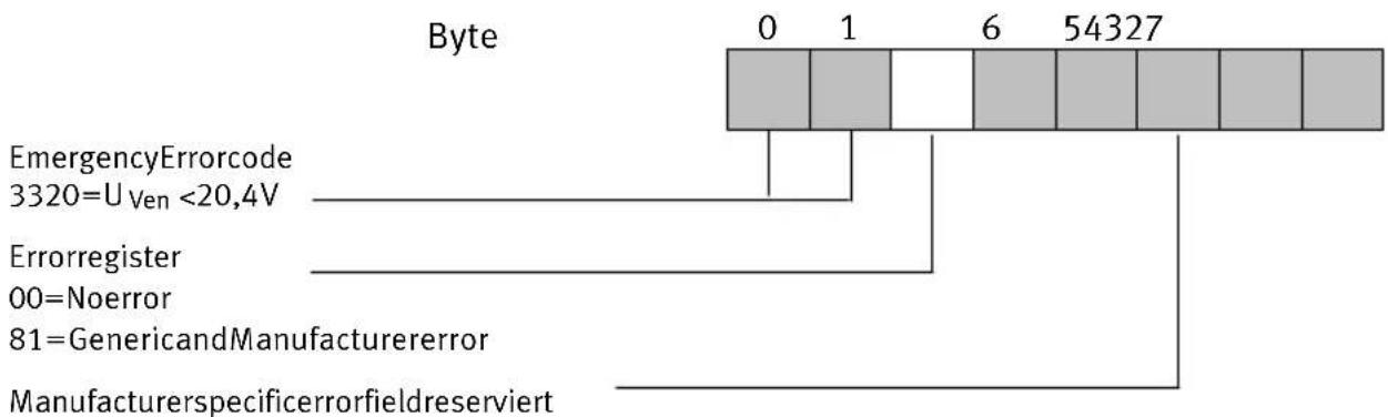
text_image
Byte 0 1 6 54327 EmergencyErrorcode 3320=U Ven <20,4V Errorregister 00=Noerror 81=GenericandManufacturererror ManufacturerspecificerrorfieldreserviertFig.2/4: Structureofemergencyobject
2.Commissioning
2.5 Basicrulesforaddressing
ACPVvalveterminalalwaysoccupies16outputs,irrespective ofthenumberofvalvesolenoidcoilsfitted.Thediagram belowshowstheaddressingsequenceoftheindividualCPV valveplates.
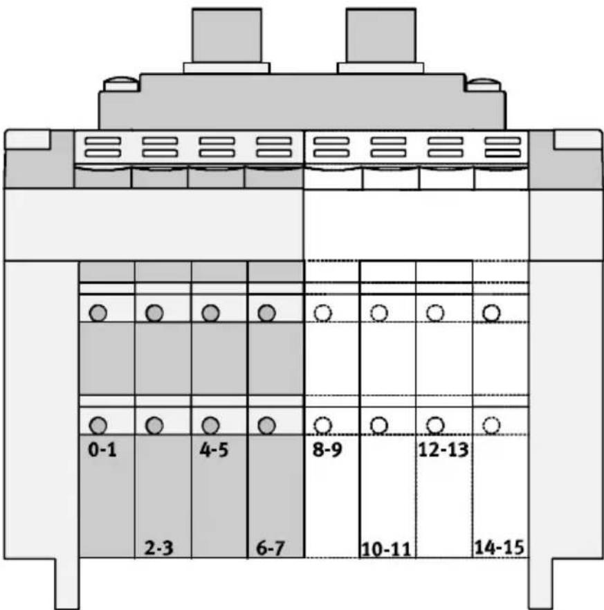
text_image
0-1 2-3 4-5 6-7 8-9 10-11 12-13 14-15Fig.2/5:AddressassignmentofaCPVvalveterminal
2.Commissioning
2.5.1 AddressingtheCPVvalveterminal
AssignmentoftheCPVvalvecoilstothedatabytes
12 LED-rowforpilot solenoid12
14 LED-rowforpilot solenoid14

text_image
12 14 12 12 12 12 12 12 12 12 12 14 14 14 14 1 3 5 7 1 3 5 7 0 2 4 6 0 2 4 6 14Fig.2/6:Assignmentofvalvecoilstodatabytes
Avalvelocationalwaysoccupies2addresseevenwhenitis fittedwithablankingplateorpressureisolatingplate bestücktist.Ifavalvelocationisfittedwithadoublesolenoid valve,thefollowingassignmentapplies:
--pilotsolenoid14occupiesthelowervalueaddress,
--pilotsolenoid12occupiesthehighervalueaddress.
Withsinglesolenoidvalves, the high value address remains unused.
2. Commissioning
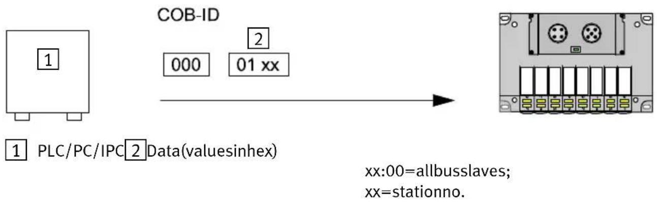
2.6Examples:communicationrun
AllexamplesrefertomoduleID=1,i.e.setCPVvalveter- minaladdress1.
flowchart
graph LR
    A["1 PLC/PC/IPC Data(valueinhex)"] --> B["COB-ID 000 01 xx"]
    B --> C["2 Data(valueinhex)"]
    C --> D["xx:00=allbusslaves; xx=stationno."]
Fig.2/7:Example1:StartCANopennetwork
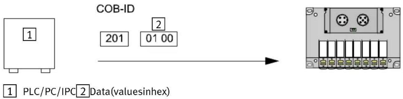
flowchart
graph LR
    A["1 PLC/PC/IPC 2 Data(valuesinhex)"] --> B["COB-ID"]
    B --> C["201 01 00"]
Fig.2/8:Example2:Setoutput0ontheCPVvalveterminal,setcoil0(1st.valve)
InordertosetvalvesontheCPVvalveterminal,thereceive PDOmustbesentbythemaster.Intheexampleonlyoutput Oisset.Anyoutputsalreadysetwillbereset.
2. Commissioning
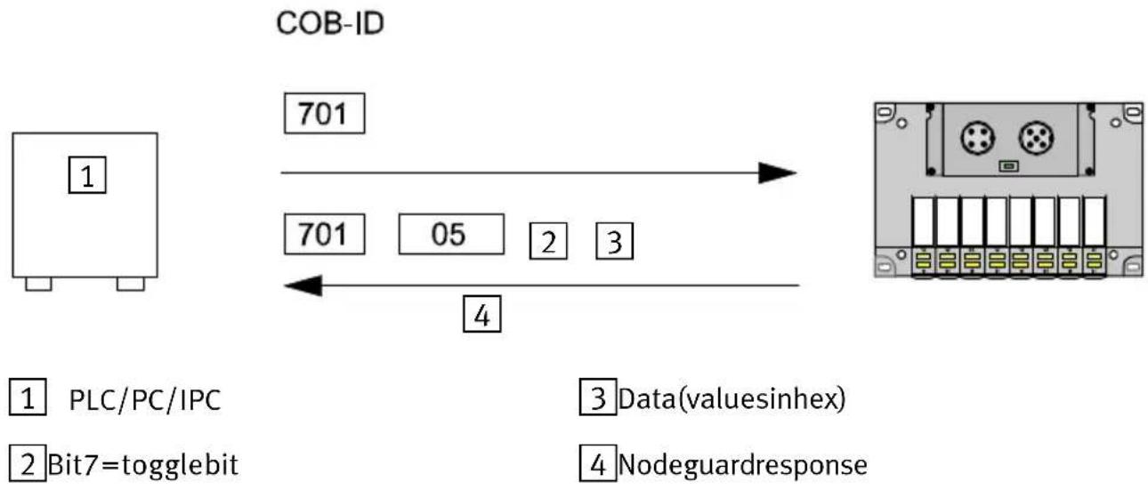
flowchart
graph LR
    A["1 PLC/PC/IPC"] --> B["COB-ID"]
    C["2 Bit7=togglebit"] --> B
    D["3 Data(valuesinhex)"] --> B
    E["4 Nodeguardresponse"] --> B
    B --> F["701 05 2 3 701"]
Fig.2/9:Example3:Startnodeguardmonitoring
Thenode guard monitoring of the CPV valvetermin CANopendirectlink starts when the first node guard telegram is received. This telegram must be cyclically repeated in the following time: guardtimex lifetime factor (index100C index100D)
If thistimeisexceeded, the valves will beswitched off for they will assumethedefault status.

Pleasenote
The timeout monitoring remains inactive in the CPV valve terminal until the first Node guard telegram is received. Valves which areswitched on remain set even after loss of communication, bus interruption, etc.
2. Commissioning

1 PLC/PC/IPC
2 Initiatedomainuploadrequest
3Index
4 Subindex
54databytes(valuesinhex)
6 Initiatedomainuploadresponse
InordertuploadobjectsofaCPVvalveterminal,theSDO mustbeloadedwiththeUploadcommand,theindexandthe subindex.TheCPVvalveterminalthensendsthenumberof databytes,theindex,thesubindexandthedatabytes.
2. Commissioning
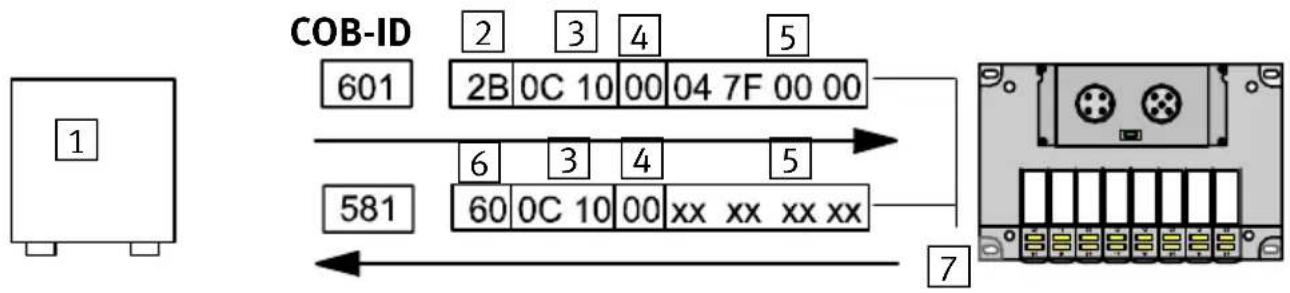
flowchart
graph TD
    A["1"] --> B["COB-ID 601"]
    B --> C["2B 0C 10 00 04 7F 00 00"]
    B --> D["581"]
    D --> E["6 0C 10 00 xx xx xx xx"]
    E --> F["7"]
1 PLC/PC/IPC
5 With2databytes(valuesinhex)
2 Initiatedomaindownloadrequest
6 Initiatedomaindownloadresponse
3Index
7 Valuesinhex
4 Subindex
xxValueisundefined
Fig.2/11:Example5:Downloadindex100C
H,subindex0(guardtime)
InordertodownloadobjectsofaCPVvalveterminal,theSDO mustbeloadedwiththeDownloadcommand,theindex,the subindexandthevalue.TheCPVvalveterminalthensends theindex,thesubindexandadatabyteasacknowledgement.
- Commissioning
Diagnosis
Chapter3
3.Diagnosis
Contents
3.Diagnosis3-1.
3.1 Summary of diagnostic possibilities 3-3.
3.2DiagnosisviaLEDs3-4.
3.2.1 Normal operating status 3-4
3.2.2 Error display 3-5
3.2.3 LED for the switching status of the valve solenoid coil 3-6
3.3 Testing the valves 3-7
3.3.1 Starting the test routine 3-8
3.3.2 Stopping the test routine 3-8
3.4 Diagnosis via the field bus 3-9
3.5 Error treatment 3-10
3.5.1 Reaction to faults in the control system 3-10
3.Diagnosis
3.1 Summary of diagnostic possibilities
TheCPVvalveterminaloffersthefollowingpossibilities of diagnosisanderrortreatment:
–Diagnosisviathebuilt-inLEDs
-valveterminalstatus
-valveterminalstatusdisplay
-Valvetest
-Diagnosisviathefieldbus.
Diagnosis via LEDs Green: Status display of operating mode
(pre-operationalmode, preparedmode, operationalmode)
Red:Errordisplay
-undervoltageatCPVvalvesor
-incorrectstationaddress(setting0)
Yellow:Valvestatusdisplay
ValvetestIntegratedtestroutineforvalves
Diagnosis via fieldbus The CPV valveterminals sends an emergency message if there is an error.
3.Diagnosis
3.2DiagnosisviaLEDs
LED display The LED on the cover of the CPV valveterminal indicate the operating status of the CPV valveterminal.
1 Module-/Network-status (red/green)
12 YellowLEDrow forpilot solenoid12
14 YellowLEDrow forpilot solenoid14

text_image
1 12 14 12 12 12 12 12 12 12 14 14 14 14Fig.3/1:LEDsoftheCPVvalveterminalwithCANopen
3.2.1 Normaloperatingstatus
InthenormaloperatingstatustheLEDDIAGlightsupgreen.


| LED | Colour | Signal | Operating status | Error treatment |
| green | normal; operational mode | none |
3.Diagnosis
3.2.2 Errordisplay
| Reaction | Signal | Colour | Operating status | Error treatment |
 |  | green/red | Operatingstatusnormalbut:-Selftestactive(LEDflashesred/geenalternately)-CPVvalveter-minalinpreoperationalmode-overrunCANerrorcounter | •Completeselftest•PutCPVvalveterminalintooperationalmode•Checkcables/plugs,reducebuslengthorbaudrate |
 |  | greenCPVval | valveterminalinpreparedmode | None |
 |  | red | -Stationnumber99 setor-Errorinstartingselftestor-Selftestactive(LEDflashesred/greenalternately) | •Correctstationnumber•Repeattest |
 |  | red | Undervoltageinvalvesupply(< 20,4V) | •Checkvoltagesupply |
3.Diagnosis
3.2.3 LED fortheswitching status of the valvesolenoid coil
ThereisayellowLEDforeachvalvesolenoidcoil. This LED indicates the switching status of the valvesolenoid coil.
| LED | Switchposition ofvalvesolenoidcoil | Meaning |
| YellowoutBasicpositionLogic0(nosignal) | ||
| Yellowalight•Switchpositionor•basicpositionbasic positionor | Logic1(signalpresent)Logic1but:-operatingvoltageofvalvesliesbelowthe permittedtolerancerange(DC <20,4V) or-faultincompressedairsupply or-pilotexhaustblocked or-servicingrequired | |
3.Diagnosis
3.3 Testingthevalves

Warning
Beforestartingthetestswitchoffthecompressed airsupplyfortheCPVvalveterminal.
You will thereby avoid undesired or dangerous movements of the actuators.

Caution
-ThetestfunctionrunsautomaticallyintheCPVvalve terminal.Allthevalvesareswitchedon/offcyclically.
-Program-technicallockingsorfurtherswitchingconditionswillnotbetakenintoaccount.
TheCPVvalveterminaloffersthefollowingtestroutines:
| Testroutine | Meaning |
| ParallelAllthevalves | vesofabyteareswitchedon/offatonesecondintervals.Switchingismadecontinuouslyfrombyte0tobyte1andviceversa. |
| SerialAllthevalves | sofabyteareswitchedon/offoneaftertheotheratonesecondintervals. |
| Switchonall valves | Allvalvesareswitchedon. |
3.Diagnosis
3.3.1 Startingthetestroutine
- Switchofftheoperatingvoltagesuppliesforthebusinterfaceandtheinternallogic.
- Removethecover(seealsoChapter2, Configuration).
- Notethesettingoftheaddresss selectorswitchandDIL switchelements.
- Setaddress99 and DIL switches1 and 2 to OFF.
- Switchontheoperatingvoltagesuppliesforthebusinterface, theinternallogicandtheCPVvalves.
- Set the desired test routine on the address selector switches as follows:
| Testroutine | Addresstobeset |
| Parallel0 | |
| Seriell1 | |
| Switchonallvalves2 |
7. Start: set DIL switches 1 and 2 to ON.
Iferrorsoccurwhentetestroutineisstarted,theredLED willflashquickly.Theprocessmustberepeated.
3.3.2 Stoppingthetestroutine
- Switchofftheoperatingvoltagesuppliesforthebusinterfaceandtheinternallogic.
- Resettheaddresss selectorswitchandtheDILswitchelementstotheiroriginalpositions.
3.Diagnosis
3.4Diagnosisviathefieldbus
The CPVvalveterminalsendstheemergencyPDOifthevoltagesupplyforthevalvesdropsbelow20.4V.

Details, structureoftheemergencyPDOetc.canbefoundin Chapter2, Commissioning.
3.5 Error treatment
3.5.1 Reaction of faults in the control system
Thevalvesreactdifferentlytoafault.Adistinctionismade betweena:
—resetbythemaster
-communicationfailure.
| Fault | Reaction |
| Reset by the master | Outputs are switched off immediately |
| Communicationfailure(bus interfaceisstillsupplied with24V) | Outputsassumethedefaultstatus afterexpiryoftime:guardtimex lifetimefactor(index100Cxindex 100D).Thedefaultstatusisdeterminedby index6206and6207. |
| Communicationfailure(bus interfaceisnolongersup- pliedwith24V) | Outputsareswitchedoffimmediately |

Pleasenote
If outputsareresetorsettothedefaultstatuswhenthere isaPLCstop,fieldbusinterruptionorfieldbusfault,the following "pneumatic rules" must be observed:
•unilaterally-actuatedvalvesmovetothebasicposition
- double-solenoidvalvesremaininthecurrentposition
- mid-positionvalvesmovetothemid-positionandare pressurized, exhaustedorblocked(dependingonvalve type).
TechnicalAppendix
AppendixA
A. Technical Appendix
Contents
A. TechnicalAppendixA-1.....
A.1 Technical specifications of the valveterminal with CANopendirectlinkA-3...
A.2 Accessories A-5
A.1 Technical specifications of the valveterminal with CANopendirect link
| General | |
| Temperaturerange:-operation-storage/transport | -5 °C ... +50 °C |
| Relativehumidity95%,noncondensing | |
| ProtectionclassasperEN60529Plugconnectorpluggedinorfittedw tectivecap | IP65with pro - |
| ProtectionagainstelectricshockProtectionagainstdirectandindirectcontactasperEN60204-1/IEC204 | bymeansofPELVpower units(ProtectedExtra-Low Voltage) |
| Protectionagainstexplosion(perEUguideline94/9/EG,EN50021 andEN50281-1-1)Donotdisconnect whenundertension! | II3G/DEExnAII T5 -5 °C ≤ Ta ≤ +50 °C T 80 °C(yearofmanufacturesee ExmarkonProduct) |
| Valves | see CPV Pneumatics manualtypeP.BE-CPV-... |
| OperatingvoltageofCPsolenoidvalves | |
| Pin2Operatingvoltageconnection-ratedvalue-tolerance | DC24V21,0...26,4V |
| Currentconsumption-Pin2 | sumofallswitchedCPvalves;seeCPVPneumaticsmanual |
| Residualripple | 4Vpp(withintolerance) |
| Powerfailurebridgingtimeduringdropinlogicvoltage | 20ms |
| Operatingvoltageforelectronicsandinputmodules | |
| Pin2,3;businterface-ratedvalue-Tolerance-Currentconsumption(24V) | externalfuserequiredDC24V;notprotectedagainstincorrectpolarity11.5...25V50mA |
| Residualripple4Vpp(withintolerance) | |
| Powerfailurebridgingtimeduringdropinlogicvoltage | 20ms |
| Electromagneticcompatibility | |
| -interferenceemission | testedasperEN55011LimitvalueclassA* |
| -resistancetointerference | testedasperEN50082-2 |
| *) The CPV valve terminal CPV..-GE-CO-8 with CANopen can also be usedwithindividualpermissioninresidentialareas(residential, businessandcommercialareas,smallfirms). | |
Informationonthepneumaticmodulescanbefoundinthe "Pneumaticsmanual,P.BE-CPV-...".
A. Technical Appendix
A.2Accessories
Thissectionprovidesasummaryofthenecessaryaccessories.

Pleasenote
The followingsummariesdonotclaimtobecomplete. The addressesofthefirmsnamedcanbefoundattheendof thesection.
Operating voltage con-nectionofCPvalves
TheoperatingvoltageconnectionoftheCPvalvesismade by a 4-pin M12 socket with PG7 or PG9 screw connected TheseconnectorscanbeorderedfromFesto:
| Design | TypePartno. | |
| PG7straight | FBSD-GD7 | 18497 |
| PG9straight | FBSD-GD9 | 18495 |
| PG7angled | FBSD-WD7 | 18524 |
| PG9angled | FBSD-WD9 | 18525 |
BusconnectionThebusmustbeconnectedviaabranchlinebymeansofa
5-pinM12socketwithPG9screwconnector.TheseconnectorscanbeorderedfromFesto:
| Design | TypePartno. | |
| PG9straightFBSD-GD9 | -5POL18324 |
Alternatively, you can use buscables (dropcable, M12/7/8") from the following manufacturers:
| Manufacturer | TypeLength | |
| LumbergRS50RKT5 | 614/1.5F | 1.5F |
| RS50RKT5-614/3F | 3.0F | |
| RS50RKT5-614/6F | 6.0F | |
| RS50RKT5-614/9F | 9.0F | |
| Turck | RSM 572-*M-RKC 4.5T/S630 | x m |
| *)Lengthinmetres | ||
Thebranchlinecanbeconnectedtothebusbymeansofa T-adapterAccessories;T-adapter(T-tap).ThefollowingT-taps areavailabletosuitthebuscablesnamed.
| Manufacturer | Type |
| LumbergTAP50-RK | |
| Turck | RSM-2RKM 57 |
| Woodhead | DN3000 |
The following manufacturers offer T-adapters with screw terminals.
| Manufacturer | Type |
| Phillips | BR50 |
| Selectron | CTA701 |
FestooffersapowerboxwithprotectionclassIP65asaT adapter:CP-FB-TBOX-SUBD9,partno.183590.
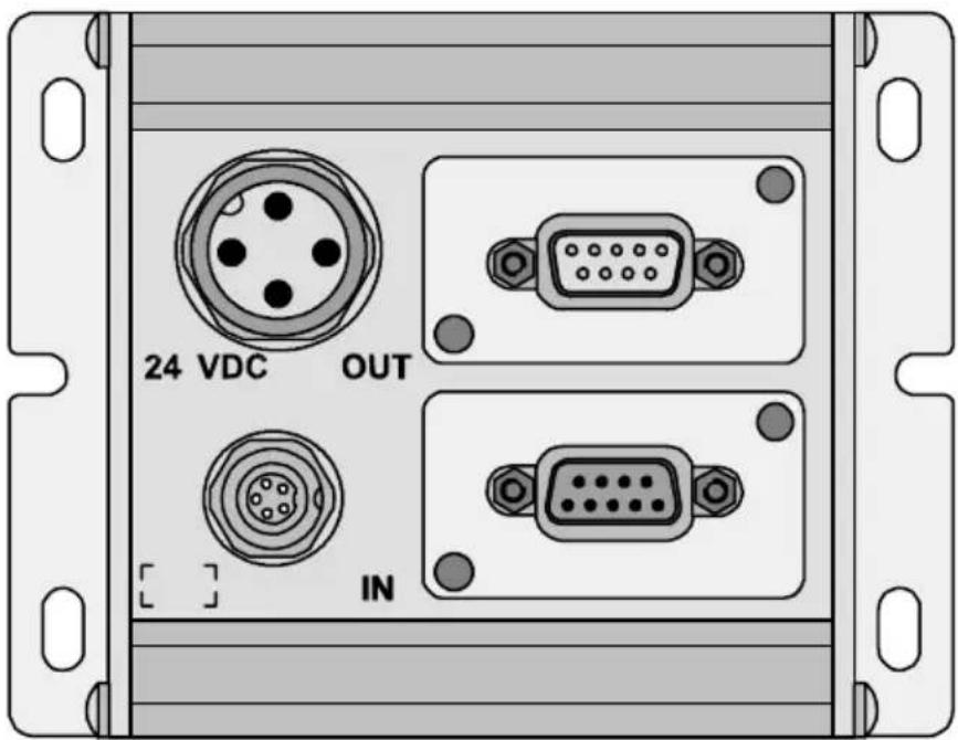
text_image
24 VDC OUT INFig.A/1:PowerboxCP-FB-TBOX-SUBD9
The following accessories are available:
| Accessory | TypePartno. | |
| Sub-Dplug,9pin,IP65 | S-SUB-9-GS-9S-SUB-9-BU9-GS-9 | 171171171172 |
| Powerconnection socketPG9-angled-straight | NTSD-WD-9NTSD-GD-9 | 1852718493 |
ConnectioncableforCANopen
| Accessory | TypePartno. | |
| Cable:Terminalconnectionangledplugtoangledsocket | KVI-CP-1WS-WD-0,5178564 | |

Pleasenote
Theready-made connection cable must be adapted to the specific connection of the power box.
Adaptionoftheterminalconnection
- Loosenthesocketfromthecable.
- Substitutethesocketbya5-pinM12socket(seeChapter 1, Connectingthebusandoperatingvoltage).
- Connect thecores as follows: 24Vbusinterface/operating voltage = yellowcore 0Vbusinterface/operating voltage = greencore CAN_h = whitecore CAN_L = browncore
Addresses:
| Manufacturer | Addresses |
| WoodheadIndustriesInc. | UnitedStatesDanielWooheadCompany3411WoodheadDriveNorthbrook,Illinois60062 |
| CanadaWoodheadCanadaLtd.1090BrevikPlaceMississauga,OntarioCanadaL4W3Y5 | |
| UnitedKingdomAero-Motive(U.K.)Ltd.9,RassauIndustrialEstateEbbwVale,Gwent,NP35SD | |
| GermanyH.F.VogelGmbHTullastraße975196Remchingen | |
| LumbergUnitedStates | LumbergInc.11351BusinessCenterDriveUSA-Richmond,VA23236 |
| UnitedKingdomLumberg(U.K.)Ltd.TheMount,HighclereGB-Newbury,Berkshire,RG209QZ | |
| GermanyLumbergGmbH & Co.Hälverstraße 9 4D-58579Schalksmühle | |
| ManufacturerAddresses | |
| TurckUnitedStates | Turcknc.3000CampusDriveUSA-Plymouth,MN55441-2656 |
| UnitedKingdomMTETurckLtd.StephensonRoadLeigh-on-Sea,EssexSS95LS | |
| GermanyHans Turck Gmbh & Co. KGWitzlebenstraße7D-45472MülheimanderRuhr | |
| PhilipsNiederlande | PMANederlandGebouwTQIII-4Postbus80025NL-5600JZEindhoven |
| GermanyPhilipsIndustrialElectronicsMiramstraße87D-34123Kassel | |
| SelectronSwiss | SelectronLyssAGIndustrielleElektronikBernstrasse70CH-3250Lyss |
| GermanySelectronSystemGmbHSchupferStraße1Postfach310262D-90202Nürnberg |
Index
AppendixB
B. Index
B.IndexB-1.
B.1Index
A
Accessories
BuscablesA-5.
ManufacturerA-7.
T-adapterA-6.
C
CANopen
COBidentifier2-7.
Defaultidentifierdistribution2-10
General information 2-4
PDO communication parameter record 2-12
Summary of object directory 2-6
COB identifier 2-7
D
Designateduse V.....
|
Important user instructions ..... VII
Information on this manual ...... VI
P
PDO, Communication parameter record 2-12
S
Service V
B. Index
T
TargetgroupV.
TechnicalspecificationsA-3.