EPCC-BS-25-25-2P-A - Pneumatic valve Festo - Free user manual and instructions
Find the device manual for free EPCC-BS-25-25-2P-A Festo in PDF.

User questions about EPCC-BS-25-25-2P-A Festo
0 question about this device. Answer the ones you know or ask your own.
Ask a new question about this device
Download the instructions for your Pneumatic valve in PDF format for free! Find your manual EPCC-BS-25-25-2P-A - Festo and take your electronic device back in hand. On this page are published all the documents necessary for the use of your device. EPCC-BS-25-25-2P-A by Festo.
USER MANUAL EPCC-BS-25-25-2P-A Festo
natural_image
Technical line drawing of a mechanical component with cylindrical body and mounting flange (no text or symbols)FESTO
Festo SE & Co. KG
Ruiter Straße 82
73734 Esslingen
Deutschland
+49 711 347-0
www.festo.com
Operating instructions
8172502
2022-03c
[8172504]

8172502
Translation of the original instructions
© 2022 all rights reserved to Festo SE & Co. KG
1 Applicable Documents
□1
All available documents for the product → www.festo.com/sp.
2 Safety
2.1 Safety instructions
- Observe labelling on the product.
- Before working on the product, switch off the power supply and secure it against being switched on again.
- Store the product in a cool, dry environment protected from UV and corrosion. Keep storage times short.
- Store the product in ambient conditions without oils, greases and grease-dissolving vapours.
2.2 Intended Use
The electric cylinder is intended to be used for positioning payloads in combination with tools or as a drive when external guides are used.
2.3 Training of qualified personnel
Work on the product may only be carried out by qualified personnel who can evaluate the work and detect dangers. The qualified personnel have knowledge and experience in dealing with electric drive systems.
3 Additional information
- Contact the regional Festo contact if you have technical problems
→ www.festo.com.
- Accessories and spare parts → www.festo.com/catalogue.
4 Product overview
4.1 Function
The electric cylinder converts the rotary motion of the mounted motor into a linear motion of the non-rotating piston rod. The lead screw converts the torque of the motor into a feed force. The linear movement of the piston rod is guided by the guide in the guide ring. Sensors enable the monitoring of end positions, reference position and intermediate position.
4.2 Product design
text_image
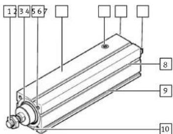
1 2 3 4 5 6 7 8 9 10Fig. 1: Product design EPCC-BS, example EPCC-BS-45-100-10P-A7-A
1 Piston rod with male thread or female thread
2 Guide ring with or without scraper
3 Threaded hole for mounting
4 Cylinder profile
5 Sealing air connection with filter element
6 Interface for motor mounting kit
7 Drive hub
8 Slot for sensor bracket
9 Slot for profile mounting
10 Slot for slot nut
5 Transport
NOTICE
Unexpected and unbraked movement of components
- Secure moving components for transport.

WARNING
Risk of injury due to falling product
If the product is lifted incorrectly, it may fall and cut, crush or separate body parts.
- Lift the product only with suitable load-bearing equipment.
-Store and transport the product in its original packaging. Observe the weight, the dimensions and the ambient conditions.
- Take the centre of gravity of the product into consideration.
-Store and transport the product in a horizontal position.
6 Assembly
6.1 Safety

WARNING
Risk of Injury due to Unexpected Movement of Components
For vertical or slanted mounting position: when power is off, moving parts can travel or fall uncontrolled into the lower end position.
- Bring moving parts of the product into a safe end position or secure them against falling.
6.2 Unpacking product
- Open packaging.
- Remove all transport materials, e.g. foils, caps, cardboard boxes.
- Remove the product from the packaging and place it on the mounting surface.
- Dispose of packaging and transport materials.
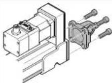
6.3 Mounting motor
i
Transverse load on the drive hub
When mounting the motor and motor mounting kit, do not exceed the maximum transverse load F_R of the drive hub, e.g. toothed belt tension when mounting the parallel kit 12.1 Technical data, mechanical.
Axial kit EAMM-A Parallel kit EAMM-U

natural_image
Technical line drawing of a mechanical component with no visible text or symbols
Tab. 1: Overview of motor mountings
Requirement
- Only loosen screws or threaded pins that are described in the directions in the instruction manuals.
- Sufficient space for reaching and mounting the sealing air connection.
- Select the motor and motor mounting kit from
Festo→ www.festo.com/catalogue.
If other motors are used: observe the critical limits for forces, torques and velocities.
- Fasten motor mounting kit, observe instruction manual
→ www.festo.com/sp.
- Fasten the motor without tension. Support large and heavy motors.
Connect motor cables only on completion of mounting.
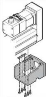
6.4 Mounting cylinder
i
High mechanical loads on the mounting connections
If high parallel torques are applied to the drive system at the same time, this will result in high mechanical loads at the mounting interfaces.
- If the mounting position is inclined or horizontal with direct fastening, the drive system will require additional support near the motor mounting.
Requirement
- No collision in the range of motion of the attachment component with motor, mounting components and sensor components.
-Sufficient space to reach maintenance interfaces.
- Sufficient space for reaching and mounting the sealing air connection.
-Flat mounting surface maximum 0.2 mm over the stroke length of the bearing surface.
-No distortion or bending when installing the product.
-
Select mounting attachments → www.festo.com/catalogue.
-
Place the mounting attachments on the support points.
-
Tighten retaining screws.
Observe the maximum tightening torque and screw-in depth.
For additional information, contact your local Festo Service.
| Direct fastening Profile mountingEAHF-L2 | Flange mountingEAHH | Swivel mountingEAHS | |
| Mounting via thread Mounting via profile groove | Mounting via profile groove | Mounting via profile groove | |
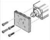 | 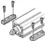 | 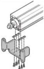 |  |
Tab. 2: Overview of mounting components for profile
| Adapter kit EAHA Swivel flange SNC... | ||
| Mounting via profile groove Mounting via thread (adapter kit EAHA) | ||
 |  | |
Tab. 3: Overview of mounting components for parallel kit
 | ||||
| Direct fastening | ||||
| Screw-M4 M5 M6 | ||||
| Max.screw-in depth tmax [mm]-8 10 12 | ||||
| Max.tightening torque [Nm]-3 4 5 | ||||
| Adapter kit EAHAFlange mounting EAHHProfile mounting EAHF-L2Swivel mounting EAHSSwivel flange SNC... | ||||
| Screw Instruction manual | →www.festo.com/sp | |||
Tab. 4: Information for mounting components
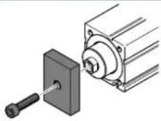
6.5 Mounting attachment component
Torque on the Piston Rod
During commissioning and operation, the piston rod may only be operated without torque.
If external torques occur, an external guide must be used.
i
Mounting the attachment component on the piston rod
When mounting the attachment component, do not exceed the maximum torque of the piston rod. The maximum torque of the piston rod may only be used for a short time during mounting Tab. 7 Information on attachment components.
| Collision-free | Torque-free | Guide load |
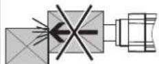 |  |  |
Tab. 5: Requirement for attachment components
Requirement:
- No collision in the range of motion of the attachment component with motor, mounting components and sensor components.
- No transverse load or torque on the piston rod.
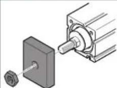
Absorb external forces and torques by an external guide. - Minimise guide load. Short lever arms from the piston rod thread to the force application points and centre of gravity of the add-on elements.
- Select accessories → www.festo.com/catalogue.
-
Screw the lock nut onto the male thread of the piston rod or attachment component.
-
Rotate or place the attachment component on the piston rod.
- Tighten lock nut.
The tightening torque must not act on the piston rod. Counterhold with a suitable tool on the spanner flat of the piston rod.
Observe maximum tightening torque.

Fig. 2: Torque-free mounting
When using an additional external guide, ensure that the electric cylinder and piston rod are aligned exactly parallel.
| EPCC-BS-... EPCC-BS-...-F | |||
| Mounting via male thread | Mounting via female thread | ||
| with nut | with screw | ||
 |  | ||
| with lock nut | |||
 |  | ||
| - Rod eye SGS, CRSGS-Rod clevis SG, CRSG-Coupling piece KSG-Self-aligning rod coupler FK; CRFK | |||
| - Rod eye SGS, CRSGS |
| -Rod clevis SG, CRSG |
| -Coupling piece KSG |
| -Self-aligning rod coupler FK; CRFK |
Tab. 6: Overview of attachment components
| Size | 25 | 32 | 45 | 60 | |
| Piston rod | |||||
| Spanner size ≤slant C [mm] | 7 | 9 | 10 | 13 | |
| Max. torque [Nm] | 0.5 | 1 | 2 | 3 | |
| Piston rod with male thread EPCC-BS-... | |||||
| Nut, lock nut | M6 | M8 | M10x1.25 M12 | x1.25 | |
| Piston rod with female thread EPCC-BS-...-F | |||||
| Screw, lock nut | M4 | M6 | M8 | M10 | |
Max. screw-in depth t_max  [mm] [mm] | 10 | 12 | 14 | 16 | |
Tab. 7: Information on attachment components
6.6 Mounting accessories
Requirement
- No collision with mounting and sensor components in the movement space of the attachment component.
Function
- Protection against uncontrolled overtravel of the end positions.
– Referencing to reference switch or end position. - Query of end positions or intermediate positions.
-
Prevention of hard impacts at the end positions.
– Prevention of contamination in the slots. -
Select accessories → www.festo.com/catalogue.
- Mount the sensor (reference or query):
Mount sensor rail or mounting kit.
- Align sensor and mount it at the switching position.
- Fasten cable.
Instruction manuals → www.festo.com/sp.
Sensor bracket EAPM
| Mounting via profile groove | ||
 | -Protect the sensor from external magnetic or ferritic influences, e.g. min. 10 mm distance to slot nuts.-Preferably use hardware limit switches with N/C contact function to guarantee protection in the event of a sensor failure.Instruction manual→ www.festo.com/sp | |
Tab. 8: Overview of sensor mountings
Connecting sealing air
The use of sealing air at approx. ± 0.02 MPa (± 0.2 bar, ± 2.9 psi) reduces or prevents subsequent contamination:
- The application of negative pressure minimises the release of abraded particles into the environment.
- The application of overpressure reduces the penetration of dirt into the drivetrain.
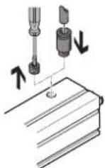
Fig. 3: Mounting fitting
1. Remove the filter element from the threaded hole.
2. Mount the screw fitting and connect the hose.
| Size 25 32 45 60 | ||||
| Thread M5 M5 G1/8 G1/4 | ||||
| Max. screw-in depth [mm] 4 5 7 7 | ||||
| Max. tightening torque [Nm] 1.4 1.4 5 8 |
Tab. 9: Information on sealing air connection
7 Commissioning
7.1 Safety
WARNING
Risk of injury due to unexpected movement of components.
- Protect the positioning range from unwanted intervention.
- Keep foreign objects out of the positioning range.
• Perform commissioning with low dynamic response.
7.2 Commissioning procedure
i
Block-shaped acceleration profiles without jerk limitation can have the following effects:
• High mechanical loads on the lead screw due to high force peaks.
• Overshooting effects during positioning.
- Rise of the entire system.
Recommendation: reduce high force peaks in the acceleration and deceleration phases by using the jerk limitation.
i
When the motor is removed, the motor encoder loses its absolute reference to the reference mark, e.g. by turning the motor drive shaft.
- Carry out a homing run every time the motor is mounted in order to establish the absolute reference between the motor encoder and the reference mark.
i
Torque on the Piston Rod
During commissioning and operation, the piston rod may only be operated without torque.
If external torques occur, an external guide must be used.
i
Running noises during operation
Identically constructed axes can generate different running noises depending on the parameterisation, mode of operation, type of mounting, installation environment and components.
i
For use with reduced particle emission
Clean product → 9.2 Cleaning.
Requirement
-Mounting of the drive system is checked.
-Installation and wiring of the motor is checked.
- No foreign objects in the movement space of the drive system.
- Maximum permissible feed force and drive torque not exceeded as a function of acceleration, deceleration (e.g. stop function, quick stop), velocity, moving mass and mounting position.
-Cylinder not mechanically overloaded and dynamic setpoint deviation not exceeded due to force peaks and torque peaks or overshoot effects, e.g. overrunning the end position.
Limit overloads and overruns by jerk limitation, reduced acceleration and deceleration setpoints or optimised controller settings.
- Control run and homing with reduced setpoint values for speed, acceleration and deceleration.
- No test run to mechanical end stops.
- Software end positions ≥ 0.25 mm away from the mechanical stops.
| Steps | Purpose Note | |
| 1. Check travel | Determine the direction of travel of the piston rod | - Direction of movement of piston rod, clockwise spindle:-Retracting: rotate drive shaft clockwise.-Advancing: rotate drive shaft anti-clockwise.-The direction of movement of the piston rod for positive and negative position values depends on the mounting position of the motor on the cylinder, e.g. parallel or axial kit.-Set a required reversal of direction of rotation via parameters in the servo drive or controller. |
| 2. Homing | Determination of the reference point and adjustment of the dimensional reference system-during the initial start-up procedure-after replacement of the motor | Permissible reference points:-towards reference switch:Travel at reduced velocity ➔ 12 Technical data.-towards end position:do not exceed maximum values ➔ Tab. 11 Speed and energy at the end positions.Additional information ➔ Instruction manual of the drive system, ➔ www.festo.com/sp. |
| 3. Test run | Checking the operating conditions | Check application requirements:-Piston rod runs through the complete travel cycle in the specified time.-The piston rod stops travel when a limit switch or software end position is reached. |
| After a successful test run, the drive system is ready for operation. | ||
Tab. 10: Commissioning steps
| Size 25 32 45 60 | ||||
| Max. stop velocity [m/s] | 0.01 | |||
| Max. stop energy [mJ] | 1.2 3.6 12 | 24 | ||
| Calculation of the maximum stop energy | ||||
| E_max = ^22 ( m + _RJ_L ) | - v = max. stop velocity-m = mass of all linear moving components-J R = mass moment of inertia of all rotating components-J L = mass moment of inertia per kg payloadAdditional information → www.festo.com/catalogue. | |||
Tab. 11: Speed and energy at the end positions
8 Operation
WARNING
Risk of injury due to unexpected movement of components.
- Protect the positioning range from unwanted intervention.
- Keep foreign objects out of the positioning range.
• Perform commissioning with low dynamic response.
i
Torque on the Piston Rod
During commissioning and operation, the piston rod may only be operated without torque.
If external torques occur, an external guide must be used.
i
Lubrication run during operation
Observe the following lubrication travel intervals.
- With working stroke less than 2 x spindle pitch... P:
- Perform a lubrication run within 10 travel cycles with a minimum stroke of ≥ 2 × spindle pitch.
9 Maintenance
9.1 Safety
WARNING
Unexpected movement of components.
Injury due to impacts or crushing.
- Before working on the product, switch off the control and secure it to prevent it from being switched back on accidentally.
9.2 Cleaning
- If the piston rod is dirty, clean it with a clean, soft and lint-free cloth without cleaning agents and then apply the lubricant thinly to the piston rod.
-Clean the other product components with a clean, soft cloth and non-abrasive cleaning agents.
For use with reduced particle emission:
- Remove abrasion and contamination from the product on the following schedule:
–Prior to initial commissioning.
- Regularly during operation.
9.3 Lubrication
Lubrication interval and accessories
| Lubrication Lead screw Piston rod | ||
| Lubrication interval Lubrication for life If required, e.g. if the grease | layer is too low. | |
| Accessories | ||
| Lubrication point — Surface | ||
| Lubricant — ELKALUB VP 922, Chemic- | Technik, Vöhringen | |
Tab. 12: Overview of lubrication intervals and accessories
10 Malfunctions
10.1 Fault clearance
WARNING
Unexpected movement of components.
Injury due to impacts or crushing.
- Before working on the product, switch off the control and secure it to prevent it from being switched back on accidentally.
WARNING
Risk of injury due to unexpected movement of components.
- Protect the positioning range from unwanted intervention.
- Keep foreign objects out of the positioning range.
• Perform commissioning with low dynamic response.
| Malfunction Possible cause Remedy | ||
| Loud running noises or vibrations or rough running of the cylinder | Coupling distance too short | Observe permissible coupling spacings ➔ Instruction manual for motor mounting kit, ➔ www.festo.com/sp. |
| Torsional stresses | - Install the cylinder free of tension. Make sure that the contact surface is flat ➔ 6.4 Mounting cylinder.-Change the layout of the attachment component, e.g. payload.-Align cylinder and attached guide element parallel to each other.-Use external guide. | |
| Current controller set- tings | Optimise controller values, e.g. velocity, acceleration, etc. | |
| Resonant vibration of the cylinder | Change the travel velocity. | |
| Wear on bearing or drive screw | - Contact local Festo Service.-Replace cylinder ➔ www.festo.com/catalogue. | |
| Insufficient lubrication of the piston rod | Lubricate piston rod ➔ 9.3 Lubrication. | |
| Vibration at the piston rod | Operation at the reso- nance point of the cyl- inder | - Change the travel velocity.-Change the acceleration.-Increase cylinder stiffness, e.g. shorter support distances.-Change the payload geometry. |
| Long oscillations of the profile | Resonant frequency of profile and payload too low. | - Increase cylinder stiffness, e.g. shorter support distances.-Change the payload geometry. |
| Piston rod does not move | Coupling slips | Check the mounting of the shaft-hub connection ➔ Instruction manual of the motor mounting kit, ➔ www.festo.com/sp. |
| Loads too high | Reduce forces and torques. Consider dynamics. | |
| Threaded drive blocked | - Contact local Festo Service.-Replace cylinder ➔ www.festo.com/catalogue. | |
| Pre-tension of toothed belt too high in parallel kit | Reduce the pre-tension of the toothed belt ➔ Instruction manual for parallel kit, ➔ www.festo.com/sp. | |
| Operation at the lower ambient temperature limit | - Optimise controller data, e.g. velocity, accel- eration, ... -Use gear unit. | |
| Piston rod jammed at the mechanical end position | Manually releasing a jam:-Switch off the controller and lock it to prevent it from being switched on again unintentionally.-Remove motor and motor mounting kit.-Rotate drive shaft freely. | |
| Overruns the end posi- tion | Sensor does not switch | Check sensor, installation and parameterisation. |
| Malfunction Possible cause Remedy | ||
| Position sensing not reproducible | Sensor switches several times | - Contact local Festo Service. |
| Idling torque too high | Wear in the drivetrain | - Contact local Festo Service.-Replace cylinder→ www.festo.com/catalogue. |
Tab. 13: Overview of fault clearance
11 Demounting
WARNING
Unexpected movement of components
Injury due to impact or crushing.
- Before working on the product: secure the slide to prevent unintentional movement.
WARNING
Risk of Injury due to Unexpected Movement of Components
For vertical or slanted mounting position: when power is off, moving parts can travel or fall uncontrolled into the lower end position.
- Bring moving parts of the product into a safe end position or secure them against falling.
- Disconnect electrical installations.
- Remove the mounted attachment component.
- Remove the mounted accessories.
- Remove motor and mounting kit.
- Remove mounting attachments.
- Observe transport information → 5 Transport.
12 Technical data
12.1 Technical data, mechanical
i
Use the Festo sizing software for sizing the drive → www.festo.com/sp.
Additional information → www.festo.com/catalogue.
EPCC-BS-25/32
| Size | 25 | 32 | |||
| Spindle pitch | 2P | 6P | 3P | 8P | |
| Design | Electric cylinder with ball screw | ||||
| Guide | Plain-bearing guide | ||||
| Mounting position | any | ||||
| Max. feed force Fx | [N] | 75 | 150 | ||
| Max. driving torque | [Nm] | 0.05 | 0.1 | 0.15 | 0.3 |
| No-load driving torque | [Nm] | 0.02 | 0.055 | 0.065 | 0.095 |
| Max. rotational speed [rpm] | 4000 3750 | ||||
| Max. velocity | [m/s] | 0.133 | 0.4 | 0.188 | 0.5 |
| → 12.2 Characteristic curves | |||||
| Max. acceleration | [m/s2] | 5 | 15 | 5 | 15 |
| Repetition accuracy | [mm] | ± 0.02 | |||
| Feed constant | [mm/rev] | 2 | 6 | 3 | 8 |
| Duty cycle | [%] | 100 | |||
| Relative humidity | [%] | 0 ... 95 (non-condensing) | |||
| Ambient temperature | [°C] | 0 ... +60 | |||
| Storage temperature | [°C] | -20 ... +60 | |||
| Degree of protection | IP40 | ||||
| Max. permissible force on the drive hub | |||||
| Max. transverse load R | [N] | 30 | 75 | ||
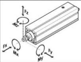
| Max. permitted forces, torques and torsional backlash on the piston rod | |||||
| Max. torsional backlash | [°] | ± 1 | |||
| Fx | [N] | 75 | 150 | ||
| Fy | [N] | → 12.2 Characteristic curves | |||
| Fz | [N] | → 12.2 Characteristic curves | |||
| Mx | [Nm] | 0 | 0 | ||
| My | [Nm] | 0.6 | 1.5 | ||
| Mz | [Nm] | 0.6 | 1.5 | ||
| Calculating the load comparison factor | |||||
| Size 25 32 | ||||
| Spindle pitch 2P 6P 3P 8P | ||||
| fv |  | |||
 | ||||
Tab. 14: General data, EPCC-BS-25/32
EPCC-BS-45/60
| Size 45 60 | ||||
| Spindle pitch 3P 10P 5P 12P | ||||
| Design Electric cylinder with ball screw | ||||
| Guide Plain-bearing guide | ||||
| Mounting position any | ||||
| Max. feed force Fx [N] 450 1000 | ||||
| Max. driving torque [Nm] 0.4 0.9 1.2 2.4 | ||||
| No-load driving torque [Nm] 0.08 0.16 0.235 0.325 | ||||
| Max. rotational speed [rpm] 3600 | 3000 | |||
| Max. velocity [m/s] | 0.18 0.6 0.25 | 0.6 | ||
| Max. acceleration [m/s2] | 5 | 15 5 | 15 | |
| Repetition accuracy [mm] | ±0.02 | |||
| Feed constant [mm/rev] | 3 | 10 5 | 12 | |
| Duty cycle [%] | 100 | |||
| Relative humidity [%] | 0 ... 95 (non-condensing) | |||
| Ambient temperature [°C] 0 ... +60 | ||||
| Storage temperature [°C] | -20 ... +60 | |||
| Degree of protection | IP40 | |||
| Max. permissible force on the drive hub | ||||
| Max. transverse load Fr [N] 180 230 | ||||
| Max. permitted forces, torques and torsional backlash on the piston rod | ||||
| Max. rotation angle [°] ±1 | ||||
| Fx [N] 450 1000 | ||||
| Fy [N] | → 12.2 Characteristic curves | |||
| Fz [N] | → 12.2 Characteristic curves | |||
| Mx [Nm] 0 | 0 | |||
| My [Nm] 2.9 6.4 | ||||
| Mz [Nm] 2.9 6.4 | ||||
| Calculating the load comparison factor | ||||
| fv |  | |||
 | ||||
Tab. 15: General data, EPCC-BS-45/60
EPCC-BS-25/32/45/60
| Size 25 32 45 60 | |||||
| Materials | |||||
| Cylinder barrel | Anodised aluminium | ||||
| Piston rod | High-alloy steel | ||||
| Spindle | Bearing steel | ||||
| Spindle nut | Bearing steel | ||||
| Weight | |||||
| Basic weight at 0 mm stroke [kg] | 0.132 | 0.225 | 0.555 | 1.114 | |
| Added weight per 10 mm stroke [kg] | 0.013 | 0.024 | 0.041 | 0.069 | |
Tab. 16: Materials and weight
12.2 Characteristic curves
Additional information → www.festo.com/catalogue.
Transverse load of piston rod EPCC-BS
Maximum transverse load Fy, Fz on the piston rod as a function of the piston rod length l
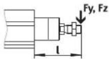
Fig. 4: Maximum transverse load Fy, Fz and piston rod length l

line
| l [mm] | Fy max, Fz max [N] (Solid) | Fy max, Fz max [N] (Dashed) | Fy max, Fz max [N] (Dash-Dot) | | ------ | -------------------------- | --------------------------- | ----------------------------- | | 0 | 10 | 10 | 10 | | 100 | 5 | 5 | 5 | | 200 | 3 | 3 | 3 | | 300 | 2 | 2 | 2 | | 400 | 1.5 | 1.5 | 1.5 | | 500 | 1.2 | 1.2 | 1.2 | | 600 | 1.1 | 1.1 | 1.1 | | 700 | 1.0 | 1.0 | 1.0 |Fig. 5: EPCC, Maximum lateral force Fy, Fz as a function of piston rod length l
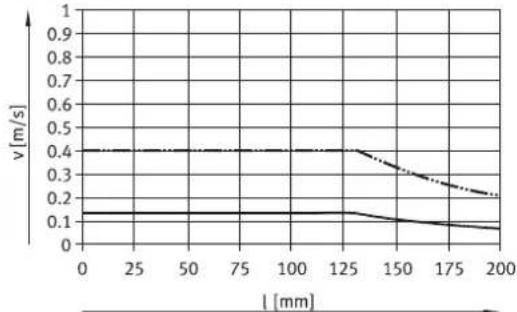
Feed speed – piston rod length EPCC-BS
Maximum feed velocity v as a function of stroke length l
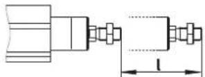
Fig. 6: Stroke length I
EPCC-BS-25-...
line
| l [mm] | v [m/s] | | ------ | ------- | | 0 | 0.1 | | 25 | 0.1 | | 50 | 0.1 | | 75 | 0.1 | | 100 | 0.1 | | 125 | 0.1 | | 150 | 0.1 | | 175 | 0.1 | | 200 | 0.1 |Fig. 7: EPCC-25, feed velocity v as a function of stroke length l

EPCC-BS-32-...

line
| l [mm] | v [m/s] | | ------ | ------- | | 0 | 0.5 | | 25 | 0.5 | | 50 | 0.5 | | 75 | 0.5 | | 100 | 0.5 | | 125 | 0.5 | | 150 | 0.5 | | 175 | 0.5 | | 200 | 0.5 |Fig. 8: EPCC-32, feed velocity v as a function of stroke length l

EPCC-BS-45-...

line
| l [mm] | v [m/s] | | ------ | ------- | | 0 | 0.6 | | 50 | 0.6 | | 100 | 0.6 | | 150 | 0.6 | | 200 | 0.6 | | 250 | 0.6 | | 300 | 0.6 |Fig. 9: EPCC-45, feed velocity v as a function of stroke length l
— EPCC-BS-45-3P EPCC-BS-45-10P
EPCC-BS-60-...

line
| l [mm] | v [m/s] | | ------ | ------- | | 0 | 0.2 | | 50 | 0.2 | | 100 | 0.2 | | 150 | 0.2 | | 200 | 0.2 | | 250 | 0.2 | | 300 | 0.2 | | 350 | 0.2 | | 400 | 0.2 | | 450 | 0.2 | | 500 | 0.2 |Fig. 10: EPCC-60, feed velocity v as a function of stroke length l
— EPCC-BS-60-5P EPCC-BS-60-12P ....