
DGST-12-50-E1A - Actuator Festo - Free user manual and instructions
Find the device manual for free DGST-12-50-E1A Festo in PDF.

| Product Type | Non-rotating twin-piston slide actuator with bearing guide |
| Model | DGST-12-50-E1A |
| Stroke Length | 50 mm |
| Pneumatic Connection | M5 |
| Operating Pressure | 0.15 … 0.8 MPa (1.5 … 8 bar, 22 … 116 psi) |
| Max. Velocity | 0.5 m/s (basic variant) |
| Theoretical Force at 6 bar (advancing) | 136 N |
| Theoretical Force at 6 bar (return) | 102 N |
| Impact Energy in End Positions (E1 variant) | 0.07 J |
| Product Weight (with 50 mm stroke) | Approx. 988 g (from max stroke weight table interpolation) |
| Ambient Temperature | −10 … +60 °C |
| Mounting Position | Any |
| Materials (Slide, Housing) | Anodised wrought aluminium alloy |
| Materials (Piston Rod) | High-alloy stainless steel |
| Seals | HNBR/PU |
| Guide Type | Recirculating ball bearing guide |
| Cushioning | Internal, elastic cushioning without end position adjustment (E1 variant) |
| Operating Medium | Compressed air to ISO 8573-1:2010 [7:4:4] |
| Lubrication | Lubricated operation possible, if used then always required |
| Maintenance | Clean with soft cloth and non-abrasive cleaners; for reduced particle emission, remove abraded particles before initial use and regularly |
| Repair | Send to Festo repair service; shock absorbers replaceable (see applicable documents) |
Frequently Asked Questions - DGST-12-50-E1A Festo
User questions about DGST-12-50-E1A Festo
0 question about this device. Answer the ones you know or ask your own.
Ask a new question about this device
Download the instructions for your Actuator in PDF format for free! Find your manual DGST-12-50-E1A - Festo and take your electronic device back in hand. On this page are published all the documents necessary for the use of your device. DGST-12-50-E1A by Festo.
USER MANUAL DGST-12-50-E1A Festo
natural_image
Isometric line drawing of a rectangular electronic device with ports and connectors (no text or symbols)FESTO
Festo SE & Co. KG
Ruiter Straße 82
73734 Esslingen
Deutschland
+49 711 347-0
www.festo.com
Operating instructions
8159550
2021-09d
[8159552]

8159550
Translation of the original instructions
© 2021 all rights reserved to Festo SE & Co. KG
1 Applicable documents
口
All available documents for the product → www.festo.com/sp.
| Documents Product Table of contents | |
| Operating instructions Shock absorber DYSS-G8 – | |
| Operating instructions Shock absorber DYEF-G8 – |
Tab. 1
2 Safety
2.1 Safety instructions
-Only use the product in its original condition without unauthorised modifications.
- Take into account the ambient conditions at the location of use.
-Observe the identifications on the product.
- Store the product in a cool, dry environment protected from UV and corrosion. Keep storage times short.
- Before working on the product, switch off the compressed air supply and lock it to prevent it from being switched on again.
2.2 Intended use
The product is intended for the space-saving transport of masses. The product is approved for slide operating mode.

Fig.1
2.3 Training of qualified personnel
Work on the product may only be carried out by qualified personnel who can evaluate the work and detect dangers. The qualified personnel have skills and experience in dealing with pneumatic (open-loop) control technology.
3 Additional information
- Contact the regional Festo contact if you have technical problems
→ www.festo.com.
- Accessories and spare parts → www.festo.com/catalogue.
4 Function
The product is a non-rotating twin-piston drive with bearing guide.
The slide is moved back and forth by alternate pressurisation of the supply ports.
The slide is braked at the end position by shock absorbers.
5 Product design

Fig.2
1 Centring
2 Thread for mounting the payload
3 Slide
4 Shock absorber with threaded sleeve
5 Drilled holes for mounting the mini slide from above
6 Slot for proximity switch
7 Thread for mounting the mini slide (concealed underneath)
8 Supply port (advance)
9 Supply port (retract)
10 Thread with centring hole for mounting the payload
6 Transport
NOTICE
Unexpected and unbraked movement of components
- Secure moving components for transport.
-
Take product weight into account → 11 Technical data.
-
Maintain the support clearance of ≤ 300 mm when attaching transportation equipment.
7 Assembly
7.1 Preparation
- Position the product to ensure that the operating elements are accessible, e.g. the clamping components for the shock absorbers.
-Mount the product without torsional stresses. - Mount the product on a mounting surface with a flatness of 0.05% of the stroke length, but max. 0.1 mm.
-If necessary: select the mounting components or the accessories. The centring sleeves are not included in the scope of delivery.
To prevent collisions: mount the mounting components outside the positioning range.
- Mount drive ensuring that the minimum number of screws is used.

- Tighten screws evenly.
| DGST | -6 | -8 | -10 | -12 | -16 | -20 | -25 | |
| Minimum number of screws dependent on the stroke | ||||||||
| 10 ... 150 | [mm] | 2 | 2 | 2 | 2 | 2 | 2 | 2 |
| 200 | [mm] | - | 3 | |||||
| Direct fastening | ||||||||
| Screw | M4 | M4 | M5 | M5 | M6 | M8 | M8 | |
| Centring [H7] | [mm] | 5 | 5 | 7 | 7 | 9 | 12 | 12 |
| Through-hole mounting | ||||||||
| Screw | M3 | M3 | M4 | M4 | M5 | M6 | M6 | |
| Centring [H7] | [mm] | 5 | 5 | 7 | 7 | 9 | 12 | 12 |
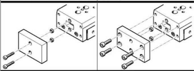
7.3 Mini slide attachment
- Mount the attachment on the slide or the yoke plate with screws and centring elements. Observe the maximum screw-in depth D.
If necessary: select the mounting components or the accessories
→ www.festo.com/catalogue. The centring sleeves are not included in the scope of delivery.
Mounting with 2 screws Mounting with 4 screws
natural_image
Technical line drawing showing two mechanical assembly configurations with screws and bolts (no text or symbols)DGST-6-8-10-12-16-20-25
| Mounting on the slide (top) | |||||||
| Screw M3 M3 M4 M4 M5 M5 M6 | |||||||
| Max. screw-in depth D [mm] 3.1 5.5 4 | 5 5.2 7.2 | 8 11 | |||||
| Centring [H7] [mm] | ∅ 5 | ∅ 5 | ∅ 5 | ∅ 5 | ∅ 5 | ∅ 12 | ∅ 12 |
| Mounting on the slide with 2 screws (front) | |||||||
| Screw – M3 M3 M4 M4 M5 M6 | |||||||
| Max. screw-in depth D [mm] – 4.7 5.2 | 6.4 6.4 | 7.4 | 7.4 | ||||
| Centring [H7] [mm] | – | ∅ 5 | ∅ 5 | ∅ 7 | ∅ 7 | ∅ 12 | ∅ 12 |
| Mounting on the slide with 4 screws (front) | |||||||
| Screw M3 M3 M4 M4 M5 M5 M6 | |||||||
| Max. screw-in depth D [mm] 4.5 | 4.5 6.5 6 | 5 8 8 10 | |||||
| Centring [H7] [mm] | ∅2H8 | ∅ 5 | ∅ 5 | ∅ 7 | ∅ 7 | ∅ 12 | ∅ 12 |
7.4 Mounting the proximity switches
For position sensing with proximity switches:

natural_image
Technical line drawing of a mechanical component with a cable inserted (no text or symbols)Fig. 3: Position sensing
-
Slide the proximity switches into the slots Fig. 3.
-
Avoid external influence caused by magnetic or ferritic parts in the vicinity of the proximity switches. Check the required clearance for the specific application.
-
To prevent contamination: use slot covers on all unused slots
→ www.festo.com/catalogue.
7.5 Mounting one-way flow control valves
To set the velocity:
- Use one-way flow control valves in the supply ports. They are screwed directly into the supply ports.
To secure the payload from dropping if the pressure fails:
- Use check valves.
8 Commissioning
8.1 Preparation
NOTICE
Unexpected movement of components.
- Keep foreign objects out of the positioning range.
- Initiate start-up at low speed.
- Slowly pressurise the complete system. Use the on-off valve HEL for slow start-up pressurisation.
With medium or large payloads or at high speeds:
- Use the sufficiently dimensioned arrester fixtures. Without the use of external arrester fixtures, the product will withstand the maximum speeds and payloads defined in the catalogue or the technical data.
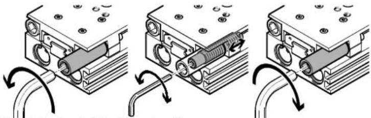
8.2 Adjustment of slide end positions
In the factory settings for the mini slide DGST-...P/-Y12 the minimum distance L of the shock absorbers specified below for the slide end positions must be observed.
natural_image
Three-step diagram showing mechanical assembly with arrows indicating motion, no text or symbols presentFig. 4: Adjustment of the slide end positions
1. Loosen the threaded sleeves.
2. Position the slides one after the other at the retracted and advanced end positions.
3. At the end position: screw in the shock absorber to the end position. Do not exceed the maximum torque when screwing the internal hexagon socket/slot. Maintain the minimum distance L. If the minimum distance L is not long enough, the shock absorbers will not be completely effective and the product will impact internally. This can lead to the destruction of the product.
| DGST | -6 | -8 | -10 | -12 | -16 | -20 | -25 | |
| Shock absorber | ||||||||
| DYEF-G8-M...-Y1 | 4 | 5 | 6 | 8 | 10 | 12 | 14 | |
| DYEF-G8-M...-Y1F | 4 | 5 | 6 | 8 | 10 | - | ||
| DYEF-G8-S-M... | 4 | 5 | 6 | 8 | 10 | 12 | 14 | |
| DYSS-G8-... | 2 | 3 | 4 | 5 | 7 | 8 | 10 | |
| Minimum distance L of the mini slide at retracted end position | ||||||||
| DGST-...-E-... | [mm] 2.1 | 0.8 | 0.5 | 0.7 | 0.8 | 1 | ||
| DGST-...-P-... | [mm] | |||||||
| DGST-...-P1-... | [mm] | 3.1 | 2.7 | 2.6 | - | - | ||
| DGST-...-Y12-... | [mm] | 2.9 | 3.1 | |||||

natural_image
Pure mechanical diagram showing a lever and shaft assembly without any text, numbers, or symbols| DGST | -6 | -8 | -10 | -12 | -16 | -20 | -25 | |
| Shock absorber | ||||||||
| DYEF-G8-M...-Y1 | 4 | 5 | 6 | 8 | 10 | 12 | 14 | |
| DYEF-G8-M...-Y1F | 4 | 5 | 6 | 8 | 10 | - | ||
| DYEF-G8-S-M... | 4 | 5 | 6 | 8 | 10 | 12 | 14 | |
| DYSS-G8... | 2 | 3 | 4 | 5 | 7 | 8 | 10 | |
| Minimum distance L of the mini slides at extended end position | ||||||||
| DGST-...-E... | [mm] 1.05 | 1.1 | 1 | 1.2 | ||||
| DGST-...-P... | [mm] | |||||||
| DGST-...-P1... | [mm] | 1.55 | 1.5 | 1.6 | - | - | ||
| DGST-...-Y12... | [mm] | 1.5 | 1.7 | |||||
At the end position: pressurise the slide as a counterhold to the shock absorber. Tighten the threaded sleeve to the specified tightening torque.
| DGST | -6 | -8 | -10 | -12 | -16 | -20 | -25 | |
| Shock absorber | ||||||||
| DYEF-G8-M...-Y1 | 4 | 5 | 6 | 8 | 10 | 12 | 14 | |
| DYEF-G8-M...-Y1F | 5 | 5 | 6 | 8 | 10 | |||
| DYEF-G8-S-M... | 4 | 5 | 6 | 8 | 10 | 12 | 14 | |
| DYSS-G8... | 2 | 3 | 4 | 5 | 7 | 8 | 10 | |
| Internal hexagon/slot on the shock absorber | ||||||||
| Max. torque [Nm] | 0.1 | 0.5 | 0.6 | 1 | 3 | 5 | 10 | |
| Threaded sleeve | ||||||||
| Tightening torque [Nm] | 0.4 | 0.64 | 0.8 | 1.6 | 2.4 | 4 | 6.4 | |
| Tolerance ± 20% | ||||||||
NOTICE
The exact slide position must be checked during a test run with compressed air applied and, if necessary, corrected.
- When operating the DGST-...-E1: restrict the speed.
- Observe the permissible impact energies → 11 Technical data.
- Suitable shock absorbers can retrofitted to the product
→ www.festo.com/catalogue.
8.3 Test run
NOTICE
Risk of collision by payloads that protrude through the rotor/slide.
- Only turn adjusting screws while the rotor/slide is stationary.

natural_image
Diagram of a device with ports and a valve, showing no text or symbolsFig.5
- Fully close the one-way flow control valves on both sides, then open them one complete revolution.
- Pressurise the drive on both sides simultaneously.
The slide moves slightly to a point of balance. - Then exhaust the drive on one side.
The slide moves to an end position. - Start the test run.
- If needed: correct speed at the one-way flow control valves. The slide should reach the end positions without striking them harshly or recoiling.
9 Cleaning
Clean the product with a clean, soft cloth and non-abrasive cleaning agents.
For use with reduced particle emission:
-Remove abraded particles and soil from the product:
-Prior to initial commissioning
- Regularly during operation
10 Malfunctions
10.1 Fault clearance
Fault description Cause Remedy
| The slide moves unevenly. The one-way flow control valves are not installed correctly. | Control the exhaust air flow. |
| The slide is in initial position despite pressurisation. | The tubing is faulty. Check the tubing. |
| The slide speed is too low. The air volume is insufficient. | - Increase the connection cross-sections.-Check the flow control valve setting.-Connect a volume upstream. |
| The slide stops in the end position without cushioning. | The speed is too high. Reduce the speed. |
| The cushioning is too low. - Re-adjust the shock absorber and the (fixed) stop 8.1 Preparation.-Reduce the speed.-Check the shock absorbers and replace if necessary. | |
| The air cushion is not present. Pressurise both supply ports simultaneously, then exhaust one side. | |
| The shock absorbers are faulty. Replace the shock absorbers. | |
| The payload is too large. Reduce the payload. |
Tab. 2: Fault clearance
10.2 Repair
Send the product to the Festo repair service for repair.
- Replacement of shock absorbers 1 Applicable documents.
11 Technical data
| DGST | -6 | -8 | -10 | -12 | -16 | -20 | -25 |
| Design | Drive with scotch yoke system | ||||||
| Guide | Recirculating ball bearing guide | Cage guide | |||||
| Mode of operation | double-acting | ||||||
| Pneumatic connection | M3 | M5 | G1/8 | ||||
| Mounting position | any | ||||||
| Ambient temperature [°C] | -10 ... +60 | ||||||
| Cushioning | |||||||
| DGST-...-E1 | Basic variant with internal, elastic cushioning without end position adjustment | ||||||
| DGST-...-E | Cushioning by external elastic shock absorbers DYEF with end-position adjustment | ||||||
| DGST-...-P | Cushioning by external elastic shock absorbers DYEF-G8 with end-position adjustment | ||||||
| DGST-...-P1 | |||||||
| DGST-...-Y12 | Cushioning by external hydraulic shock absorbers DYSS-G8 with end-position adjustment | ||||||
| DGST | -6 | -8 | -10 | -12 | -16 | -20 | -25 | |
| Max. velocity | ||||||||
| DGST-...-E/-P | [m/s] | 0.5 | 0.8 | |||||
| DGST-...-E1/-P1/-Y12 | [m/s] | 0.5 | ||||||
| Repetition accuracy | ||||||||
| DGST-...-E/-P/-E1 [mm] | ≤0.3 | |||||||
| DGST-...-P1/-Y12 | [mm] | ≤0.02 | ||||||
| Operating conditions | ||||||||
| Operating medium | Compressed air to ISO 8573-1:2010 [7:4:4] | |||||||
| Information on the operating medium | lubricated operation possible, in which case lubricated operation will always be required | |||||||
| Operating pressure^1) | [MPa] | 0.15 ... 0.8 | 0.1 ... 0.8 | |||||
| [bar] | 1.5 ... 8 | 1 ... 8 | ||||||
| [psi] | 22 ... 116 15 ... 116 | |||||||
| Theoretical force | ||||||||
| at 6 bar (advancing) | [N] | 34 | 60 | 94 | 136 | 241 | 377 | 589 |
| at 6 bar (return) | [N] | 25 | 45 | 79 | 102 | 207 | 317 | 495 |
| Impact energy in the end positions | ||||||||
| DGST-...-E/-P | [J] | 0.018 | 0.05 | 0.08 | 0.12 | 0.25 | 0.35 | 0.45 |
| DGST-...-E1 | [J] | 0.012 | 0.03 | 0.05 | 0.07 | 0.15 | 0.2 | 0.3 |
| DGST-...-P1 | [J] | 0.005 | 0.02 | 0.03 | 0.04 | 0.06 | - | - |
| DGST-...-Y12 (per stroke) | [J] | 0.09 | 0.18 | 0.28 | 0.48 | 0.85 | 1.9 | 3.6 |
| Max. operating frequency | ||||||||
| DGST-...-Y12 | [cycles/min] | 50 | 80 | 80 | 80 | 70 | 50 | 50 |
| Product weight | ||||||||
| DGST-...-E1 with 10 mm stroke | [g] | 90 | 129 | 247 | 391 | 454 | 978 | 1463 |
| DGST-...-E1 at max. stroke | [g] | 172 | 310 | 561 | 988 | 1402 | 3275 | 4803 |
| Materials | ||||||||
| Slide, housing | Anodised wrought aluminium alloy | |||||||
| Piston rod | high-alloy stainless steel | |||||||
| Guide | high-alloy steel, POM, TPE | |||||||
| Seals | HNBR/PU | |||||||
1) With DGST-6/-8/-10/-12 the minimum operating pressure may increase slightly after downtime of >24 h.
Tab. 3: Technical data DGST


- Safety
- Safety instructions
- Intended use
- Training of qualified personnel
- Additional information
- Function
- Transport
- NOTICE
- Unexpected and unbraked movement of components
- Assembly
- Preparation
- Mini slide attachment
- Mounting the proximity switches
- Mounting one-way flow control valves
- Commissioning
- Preparation
- Unexpected movement of components.
- Adjustment of slide end positions
- Test run
- Fig.5
- Cleaning
- Malfunctions
- Fault clearance
- Repair
Brand : Festo
Model : DGST-12-50-E1A
Category : Actuator