DGSL-20-150-P1A - Unspecified Festo - Free user manual and instructions
Find the device manual for free DGSL-20-150-P1A Festo in PDF.

User questions about DGSL-20-150-P1A Festo
0 question about this device. Answer the ones you know or ask your own.
Ask a new question about this device
Download the instructions for your Unspecified in PDF format for free! Find your manual DGSL-20-150-P1A - Festo and take your electronic device back in hand. On this page are published all the documents necessary for the use of your device. DGSL-20-150-P1A by Festo.
USER MANUAL DGSL-20-150-P1A Festo
natural_image
Technical line drawing of a mechanical assembly with no visible text or symbolsFESTO
Festo SE & Co. KG
Ruiter Straße 82
73734 Esslingen
Deutschland
+49 711 347-0
www.festo.com
Operating instructions
8166553
2021-11i
[8166555]

8166553
Translation of the original instructions
© 2021 all rights reserved to Festo SE & Co. KG
1 Applicable Documents
口
All available documents for the product → www.festo.com/sp.
2 Safety
2.1 Safety instructions
- Take into account the ambient conditions at the location of use.
-Only use the product in its original condition without unauthorised modifications. - Observe the identifications on the product.
-Store the product in a cool, dry environment protected from UV and corrosion. Keep storage times short. - Before working on the product, switch off the compressed air supply and lock it to prevent it from being switched on again.
- Have the product repaired by the Festo repair service only.
-Observe the tightening torques. Unless otherwise specified, the tolerance is ± 20% .
2.2 Intended use
The product is intended for the space-saving transport of masses. The product is approved for slide operating mode.
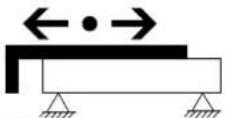
Fig.1
2.3 Foreseeable misuse
Operating the product without cushioning components will result in damage. The product may be destroyed if the slide is moved without a (fixed) stop.
- Use suitable cushioning components → www.festo.com/catalogue.
2.4 Training of qualified personnel
Work on the product may only be carried out by qualified personnel who can evaluate the work and detect dangers. The qualified personnel have skills and experience in dealing with pneumatic (open-loop) control technology.
3 Additional information
- Contact the regional Festo contact if you have technical problems
→ www.festo.com. - Accessories and spare parts → www.festo.com/catalogue.
4 Function
The product is a non-rotating single-piston drive with bearing guide.
The slide is moved back and forth by alternate pressurisation of the supply ports.
The slide is braked at the end position by shock absorbers.
-For DGSL-...-E/-P/-P1: by external elastic shock absorbers.
- For DGSL-...-Y3/-Y11: with external hydraulic shock absorbers.
5 Product design
text_image
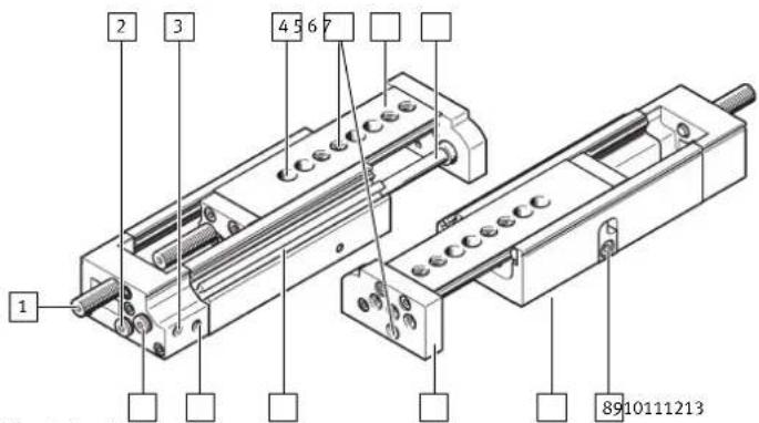
1 2 3 4 5 6 7 8910111213Fig. 2: Product design
1 Cushioning component:
- DGSL-...-E/-P/-P1: elastic
- DGSL-...-Y3/-Y11: hydraulic
- DGSL-...-N: without
2 Supply port: retract, with plug screw
3 Supply port: advance
4 Drilled hole for mounting the mini slide, concealed
5 Thread with centring recess for mounting the payload
6 Slide with bearing guide
7 Piston rod
8 (Fixed) stop
9 Thread with centring recess for mounting the mini slide, concealed
10 Yoke plate
11 Slots for proximity switches
12 Supply port: retract
13 Supply port: advance, with plug screw
6 Transport and storage
NOTICE
Unexpected and unbraked movement of components
- Secure moving components for transport.
• Do not store near magnets.
7 Assembly
7.1 Preparation
- Position the product to ensure that the operating elements are accessible, e.g. the clamping components for the shock absorbers.
-Mount the product without torsional stresses.
-If necessary: select the mounting components or the accessories.
To prevent collisions: mount the mounting components outside the positioning range.
7.2 Mounting
- Select a suitable adapter plate.
- To make the through-holes accessible, move the slide to the retracted end position.
- Use the included centring sleeves.
- Mount the product according to the type of mounting according to stroke.
| DGSL-... | -10 ... -40 | -50 ... -200 |
| Base-surface mounting with - Through-holes - Centring recess and cen- tring sleeves | ||
| Required retaining screws | 2 | 3 |
| DGSL-... | -10 ... -40 | -50 ... -200 |
| Base-surface mounting with - Through-holes - Centring recess and cen- tring sleeves | ||
| Required retaining screws | 2 | 3 |
7.3 Attachment
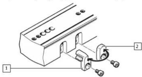
7.3.1 Attachment of yoke plate

text_image
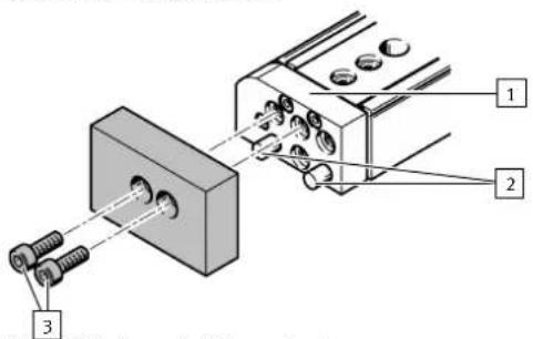
Technical diagram showing two mechanical assembly steps with labeled components and directional arrows indicating movement or force.Fig. 3: Securing yoke plate
1 Housing
3 Metal plate
2 Yoke plate
4 Centring pins
-
Push a metal plate [3] between the yoke plate [2] and the housing [1] as a counter holder.
-
Press the centring pins [4] manually into the yoke plate.
i
Do not hammer in the centring pins.
7.3.2 Attaching the payload
text_image
Technical diagram showing mechanical assembly with labeled parts 1, 2, and 3Fig. 4: Attachment of the payload
1 Yoke plate
3 Retaining screws
2 Centring pins
- Position the payload on the yoke plate [1].
- Fasten the payload with the retaining screws [3].
8 Installation
8.1 Installation of proximity switches
i
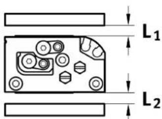
To avoid faulty switching and external influences, observe the minimum distances L_1 and L_2 between the static and moving ferritic masses and proximity switches.
text_image
L₁ L₂Fig. 5: Minimum distances
| DGSL-... -4 -6 -8 -10 -12 -16 -20 -25 | ||||||||
| L1 to ferritic materials | [mm] 5 5 0 | |||||||
| L2 to ferritic materials | [mm] 15 0 | |||||||
Tab. 1: Minimum distances
text_image
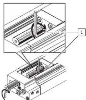
Technical diagram of a mechanical assembly with labeled component '1'Fig. 6: Position detection with proximity switch
1
Slots for proximity switches
- Position the proximity switches in the slots [1].
i
Use the lower slot for the DGSL-...-4 and DGSL-...-8 products.
- Temporarily lock the proximity switch.
- After the test run, mount the proximity switch in the suitable position.
8.2 Rough setting of end positions
- Position the slide at the desired end position by hand. Leave the slide in the retracted end position during the setting procedure.

natural_image
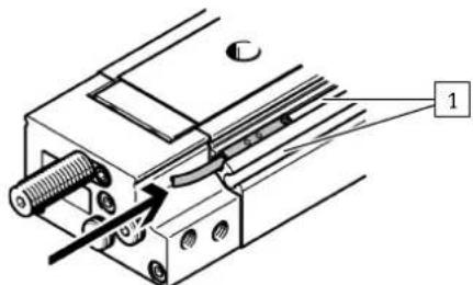
Technical line drawing of a mechanical assembly with no visible text or symbols- Unscrew the retaining screws of the (fixed) stop 1 and the orifice 2.
-Certain product variants allow coarse adjustment of the front-end position www.festo.com/catalogue.
-A stroke reduction of max. 2 standard strokes is possible in combination with the precision adjustment.
- Replace the (fixed) stop 1 with the orifice 2.
text_image
Technical diagram of a mechanical assembly with numbered components and labeled parts- Screw in the retaining screws. Observe the tightening torque.
| DGSL-... -4 -6 -8 -10 -12 -16 -20 -25 | |||||||||
| Tightening torque | [Nm] | 0.76 | 1.3 | 1.3 | 2.9 | 2.9 | 6 | 9 | 9 |
- Carry out the precision adjustment of the end positions on the cushioning components.
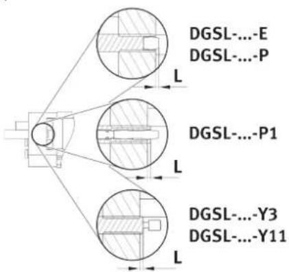
8.3 Installation of cushioning components
Cushioning components for the DGSL-...-N product must be attached at both end positions.
text_image
DGSL-...E DGSL-...P L DGSL-...P1 L DGSL-...Y3 DGSL-...Y11 LFig. 7: Minimum distance L of the cushioning components
| DGSL-... -4 -6 -8 -10 -12 -16 -20 -25 | |||||||||
| Distance L with [mm] 1 1.5 DGSL-...-E/-P/-P1 | |||||||||
| Distance L with [mm]- - 1.5 DGSL-...-Y3/-Y11 | |||||||||
Tab. 2: Minimum distances
| DGSL-....-E/-P DGSL-....-P1 | DGSL-....-Y3/-Y11 | |
| no metallic stop metallic stop | ||
| The rubber buffer touches the slide. | The stop sleeve touches the slide against the force of the cushioning. | The shock absorber housing/reducing sleeve (with DGSL-...-Y11) touches the slide against the force of the shock absorber. |
DGSL-...-E/-P DGSL-...-P1 DGSL-...-Y3/-Y11
Tab. 3: End position cushioning components
| DGSL-... -4 -6 -8 -10 | ||||
| Only for DGSL-...-Y3 | ||||
| Max. torque, cushioning com- [Nm]-- 0.5 0.8 ponent | ||||
| Shock absorber DYSW-...-Y1F [Nm]-- 4 ... 6 5 ... 8 | ||||
| Only for DGSL-...-Y11 | ||||
| Max. torque reducing sleeve [Nm]--- 0.8 | ||||
| Max. torque cushioning com- [Nm]-- 0.5 ponent | ||||
| Shock absorber DYSW-...-Y1F [Nm]--- 4 ... 6 | ||||
Tab. 4: Tightening torque
| DGSL-.... -12 -16 -20 -25 | ||||
| Only for DGSL-....-Y3 | ||||
| Max. torque, cushioning com- [Nm] 2.2 5 8 13ponent | ||||
| Shock absorber DYSW-....-Y1F [Nm] 7 ... | 10 8 ... 14 10 ... | 17 | 12 ... 20 | |
| Only for DGSL-....-Y11 | ||||
| Max. torque reducing sleeve [Nm] 2.2 5 8 13 | ||||
| Max. torque cushioning com- [Nm] 0.8 2.2 5 8ponent | ||||
| Shock absorber DYSW-....-Y1F [Nm] 5 ... | 8 7 ... 10 8 ... 14 | 10 ... 17 | ||
Tab. 5: Tightening torque
9 Commissioning
9.1 Precision adjustment of the end positions
i
Note
Check the correct positioning of the slide under compressed air. Correct the positioning.
text_image
Technical diagram showing mechanical assembly with labeled component '1'Fig. 8: Position of the clamping components
1. Loosen the clamping components [1].
2. Position the slide at the desired end position by hand.
3. Turn the cushioning component with a hex wrench until the end position is reached.
4. Tighten the clamping component.
| DGSL-... -4 -6 -8 | -10 -12 -16 | -20 -25 | ||||||||
| Tightening torque of clamping component | [Nm] | 0.15 | 0.2 | 0.3 | 0.8 | 1.2 | 2.5 | 2.5 | 3.5 | |
9.2 Test run
text_image
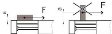
F a a FFig. 9: Positioning payload
- Position the payload on the slide. Position the centre of gravity of the payload as low as possible.
- Close the one-way flow control valves.
natural_image
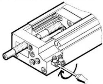
Technical line drawing of a mechanical assembly with gears and a screw (no text or symbols)- Open the one-way flow control valves by one revolution.
- Pressurise the drive. Slowly pressurise with an on-off valve.
The slide moves to an end position.
- Start a test run with a moveable mass.
-
Take the following into account in the test run:
-
The speed and the acceleration of the moveable mass
- The end position
- The mass of the payload
- The position of the proximity switches
- Only make changes when the slide is stationary.
- Unscrew the one-way flow control valves until the required speed of the slide is reached.
i
An increased speed when approaching the end position can result in the slide rebounding from the end position.
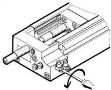
natural_image
Technical line drawing of a mechanical assembly with no visible text or symbols- Fix the proximity switches in the final positioning position.
10 Maintenance
10.1 Replacement of cushioning components
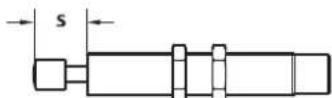
Fig. 10: Cushioning distance s
- Check the cushioning elements every 2 million cycles.
- Check the cushioning length s → 12 Technical data
- Replace the cushioning components if there are signs of wear.
- Replace the cushioning components after max. 5 million cycles.
10.2 Cleaning
Clean the product with a clean, soft cloth and non-abrasive cleaning agents. For use with reduced particle emission:
- Remove abraded particles and soil from the product:
- Prior to initial commissioning
- Regularly during operation
10.3 Lubrication
i
Note
Check the need for shorter lubrication intervals:
- At high temperatures.
- With excessive dirt accumulation.
-
In the vicinity of grease-dissolving liquids or grease-dissolving vapours.
-
Lubricate the product as required.
-
Lubricate the piston rod and the guide rail.
Use the following lubricant:
Festo LUB-KC1
- Move the slide by hand for even lubrication.
11 Fault clearance
| Fault description Cause Remedy | ||
| The slide moves unevenly. The one-way flow control valves are not installed correctly. | Control the exhaust air flow. | |
| The slide is in initial position despite pressurisation. | The tubing is faulty. Check the tubing. | |
| The slide speed is too low. The air volume is insufficient. -Increase the connection cross-sections.-Check the flow control valve setting.-Connect a volume upstream. | ||
| The slide stops in the end position without cushioning. | The speed is too high. Reduce the speed. | |
| The cushioning is too low. -Re-adjust the shock absorber and the (fixed) stop → 9 Commissioning.-Reduce the speed.-Check the shock absorbers and replace if necessary. | ||
| The air cushion is not present. Pressurise both supply ports simultaneously, then exhaust one side. | ||
| The shock absorbers are faulty. Replace the shock absorbers. | ||
| The payload is too large Reduce the payload. | ||
| The proximity switches have no function. | The slide has been magnetised. Contact Festo → www.festo.com. | |
Tab. 6: Fault clearance
12 Technical data
| DGSL-... | -4 -6 | -8 | -10 | ||
| Design | double-acting drive with Scotch yoke system and ball-bearing cage guide | ||||
| Mounting position | any | ||||
| Cushioning | |||||
| DGSL-...-E/-P | elastic cushioning, without metallic end position, at both ends | ||||
| DGSL-...-P1 | elastic cushioning, with metallic end position, metal end positions at both ends | ||||
| DGSL-...-Y3 | - | with progressive shock absorber and metallic end position, both ends | |||
| DGSL-...-Y11 | - | with pro-gressive shock absorber and metallic end posi-tion, both ends | |||
| DGSL-...-N | - | without cushioning | |||
| Operating conditions | |||||
| Operating medium | Compressed air to ISO 8573-1:2010 [7:4:4] | ||||
| Information on the operating medium | lubricated operation possible, in which case lubricated operation will always be required | ||||
| Operating pressure | [MPa] 0.25 ... 0.8 0.15 ... 0.8 | ||||
| [bar] 2.5 ... 8 1.5 ... 8 | |||||
| [psi] | 36 ... 116 | 22 ... 116 | |||
| Ambient temperature [°C] | 0 ... 60 (observe temperature range of proximity switches) | ||||
| Repetition accuracy | |||||
| DGSL-...-E/-P | [mm] | 0.3 | |||
| DGSL-...-P1/-Y3/.../-Y11 | [mm] | ±0.01 | |||
| Materials | |||||
| Note on materials | Free of copper and PTFE | ||||
| Housing, cover, yoke plate | Anodised wrought aluminium alloy | ||||
| Screws | Steel | ||||
| Piston rod, slide, adjusting screw | High-alloy stainless steel | ||||
| Cover, stops, driver | Beryllium bronze, nickel-plated | ||||
| Buffer | Nitrile rubber | ||||
| Seals | Hydrated nitrile rubber, polyurethane | ||||
Tab. 7: Technical data DGSL, size 4 ... 10
| DGSL-... | -12 | -16 | -20 | -25 |
| Design | double-acting drive with Scotch yoke system and ball-bearing cage guide | |||
| Mounting position | any | |||
| Cushioning | ||||
| DGSL-...-E/-P | elastic cushioning, without metallic end position, at both ends | |||
| DGSL-...-P1 | elastic cushioning, with metallic end position, metal end positions at both ends | |||
| DGSL-...-Y3 | with progressive shock absorber and metallic end position, both ends | |||
| DGSL-... | -12 | -16 | -20 | -25 | |
| DGSL-...-Y11 | with progressive shock absorber and metallic end position, both ends | ||||
| DGSL-...-N | without cushioning | ||||
| Operating conditions | |||||
| Operating medium | Compressed air to ISO 8573-1:2010 [7:4:4] | ||||
| Information on the operating medium | lubricated operation possible, in which case lubricated operation will always be required | ||||
| Operating pressure | [MPa] 0.1 ... 0.8 | ||||
| [bar] 1 ... 8 | |||||
| [psi] | 14.5 ... 116 | ||||
| Ambient temperature [°C] | 0 ... 60 (d | observe temperature range of proximity switches) | |||
| Repetition accuracy | |||||
| DGSL-...-E/-P | [mm] | 0.3 | |||
| DGSL-...-P1/-Y3/.../-Y11 | [mm] | ±0.01 | |||
| Materials | |||||
| Note on materials | Free of copper and PTFE | ||||
| Housing, cover, yoke plate | Anodised wrought aluminium alloy | ||||
| Screws | Steel | ||||
| Piston rod, slide, adjusting screw | High-alloy stainless steel | ||||
| Cover, stops, driver | Beryllium bronze, nickel-plated | ||||
| Buffer | Nitrile rubber | ||||
| Seals | Hydrated nitrile rubber, polyurethane | ||||
Tab. 8: Technical data DGSL, size 12 ... 25
| DGSL-... | -4 -6 | -8 -10 | |||
| Impact energy at the end positions | |||||
| DGSL-...E/-P | [Nm] | 0.015 | 0.05 | 0.08 | 0.12 |
| DGSL-...P1 | [Nm] | 0.005 | 0.02 | 0.03 | 0.04 |
| DGSL-...Y3 | [Nm] | - | - | 0.5 | 1 |
| DGSL-...Y11 | [Nm] | - | - | - | 0.5 |
| Theoretical force at 0.6 MPa (6 bar, 87 psi) | |||||
| Advancing | [N] 17 30 | 47 | 68 | ||
| Retracting | [N] 13 23 | 40 | 51 | ||
| Max. permissible forces and torques | → www.festo.com/catalogue. | ||||
| Max. velocity | [m/s] | 0.5 | 0.5 | 0.8 | 0.8 |
| Weight min. stroke | [kg] | 0.08 | 0.16 | 0.74 | 0.4 |
| Weight max. stroke | [kg] | 0.1 | 0.23 | 0.45 | 0.8 |
Tab. 9: Technical data DGSL, size 4 ... 10
| DGSL-... | -12 | -16 | -20 | -25 | |
| Impact energy at the end positions | |||||
| DGSL-...-E/-P | [Nm] | 0.25 | 0.35 | 0.45 | 0.55 |
| DGSL-...-P1 | [Nm] 0.06 | 0.12 | 0.2 | 0.25 | |
| DGSL-...-Y3 | [Nm] | 2 | 4 | 7 | 10 |
| DGSL-...-Y11 | [Nm] | 1 | 2 | 4 | 7 |
| Theoretical force at 0.6 MPa (6 bar, 87 psi) | |||||
| Advancing | [N] | 121 | 188 | 295 | 483 |
| Retracting | [N] | 104 | 158 | 247 | 415 |
| Max. permissible forces and torques | → www.festo.com/catalogue. | ||||
| Max. velocity | [m/s] | 0.8 | 0.8 | 0.8 | 0.8 |
| Weight min. stroke | [kg] | 0.6 | 0.9 | 1.5 | 2.5 |
| Weight max. stroke | [kg] | 1.5 | 2.0 | 4.3 | 6.1 |
Tab. 10: Technical data DGSL, size 12 ... 25
| DYSW-... | -4 ... -6 | -5 ... -8 | -7 ... -10 | |
| Cushioning distance (s) [mm] | 6 | 8 | 10 | |
| Max. energy absorption per stroke | [l] | 0.8 | 1.3 | 2.5 |
| Max. energy absorption per hour | [k] | 7 | 10 | 15 |
Tab. 11: Technical data DYSW
| DYSW-... | -8 ... -14 -10 ... | 17 | -12 ... | 20 | |
| Cushioning distance (s) [mm] | 14 | 17 | 20 | ||
| Max. energy absorption per stroke | [J] | 4 | 8 | 12 | |
| Max. energy absorption per hour | [k] | 21 | 30 | 41 | |
Tab. 12: Technical data DYSW