PDU41404 - Inverter CyberPower - Free user manual and instructions
Find the device manual for free PDU41404 CyberPower in PDF.

User questions about PDU41404 CyberPower
0 question about this device. Answer the ones you know or ask your own.
Ask a new question about this device
Download the instructions for your Inverter in PDF format for free! Find your manual PDU41404 - CyberPower and take your electronic device back in hand. On this page are published all the documents necessary for the use of your device. PDU41404 by CyberPower.
USER MANUAL PDU41404 CyberPower
Intelligent PDU/ATS User Guide
PDU31xxx
PDU41xxx
PDU71xxx
PDU81xxx
PDU34xxx
PDU44xxx
PDU74xxx
PDU84xxx

text_image
PDU Remote Management Summary PDU Enter Leg System Help Summary Current Condition • RDU is accepted • Environment status is accepted PDU Status Status: 100% Status: 7 System Date Name: PDU-2001 Location: Absolute Location Contact: Administrator Rating: EBA Operator: Supply Mio. Motor, Binaer Phone: 2017/06/27 to 06/23 Service Status: Temperature: 30.4°C Intensity: 45%RH Service Date: Owner: Performance Location: Service Status Recommended Service Status: Name: Company 2017/06/27 16:45:29 Date: short time period until 1 July 2017 GMT 12 PMED/06/28 or 1 July 2017 2017/06/27 16:45:29 Post-day cost breakdown, the value is assigned to UnitTable of Contents
Web Interface .... 1
Introduction....1
Advanced Power Management....10
Outlet Management 41
Security 59
Network Service....69
PDU/ATS Information....82
Command Line Interface 84
Introduction 84
Command Lists 86
Save and Restore Configuration Settings.... 116
PDU/ATS Network Daisy Chain....120
Firmware Upgrade....125
Web Interface
Introduction
CyberPower's Intelligent Power Distribution Unit (PDU) and Automatic Transfer Switch (ATS) Web Interface gives users all the features they need to configure, manage, and monitor the Intelligent PDU/ATS Series via a Web browser. With this easy-to-navigate interface, users can perform real-time monitoring of each outlet, control individual outlet, set power alerts, and complete many other tasks in an intuitive manner.
How to Log in
CyberPower
PDU Remote Management

text_image
Remote Management - LOGIN Name cyber Password ...... Automatic Login LOGIN© 2010-2016, CyberPower Systems, Inc. All rights reserved.
- Open a Web browser.
- Enter the IP address of the CyberPower PDU/ATS in the Browser Address Bar, and then press ENTER.
Note: To look up the IP address, please refer to the LCD screen of the PDU/ATS.
- Enter the information for the User Name and Password fields.
There are two types of user accounts.
| Account Type | Default User Name | Default Password | Authorization |
| Administrator | cyber | cyber | View, access, and control all settings. |
| Viewer | device | cyber | View all settings. |
- Click LOGIN to open the Summary Tab.
General Settings
These are the basic settings for the PDU/ATS.
1. Date and Time Settings
The date and time can be set manually or synchronized with a Network Time Protocol (NTP) server. All time-related configurations are based on this setting. See System Tab > General > Time.
System Tab > General > Time

text_image
PDU Remote Management Administrator login from 192 168.25 26 [Logout] Summary | PDU | Envir | Log | System | Help General Time Identification Daylight Saving Time Security Network Service Notification Reset/Reboot About Time Current Settings Time 2017/07/25 Tuesday & 16:15:28 Status Update from manual input. Next NTP Update System Time Configuration Time Zone GMT+08:00 ▼ Date Format yyyy/mm/dd ▼ Using NTP Server Primary NTP Server 0.0.0.0 Secondary NTP Server 0.0.0.0 Update Interval 8759 [1-8760 Hour(s)] Update right now Manual Setup Date 2017 / 7 / 26 yyyy/mm/dd Time 16:15:28 hh:mm:ss Apply Reset| Item | Definition |
| Current Settings | |
| Time | The current date and time. |
| Status | Show whether the date and time setting is updated by manual setup or by the NTP (Network Time Protocol) server. |
| Next NTP Update | Synchronize with Update Interval. |
| System Time Configuration | |
| Time Zone | The options for time zone selection. |
| Date Format | The options for date format selection. |
| Using NTP Server | *Primary NTP Server: Users enter the IP address/domain name of the NTP server and choose local time zone based on their location.*Secondary NTP Server: Users enter the IP address/domain name of the NTP server and choose local time zone based on their location.*Update Interval: The frequency for updating the date and time from the NTP server.Select the Update right now option to update immediately. |
| Manual Setup | *Date: Enter the date in the designated format.*Time: Enter the time in the designated format. |
2. Daylight Saving Time
Users adjust the daylight saving time according to their location. See System Tab > General > Daylight Saving Time.
System Tab > General > Daylight Saving Time

text_image
PDU Remote Management Administrator login from 192.168.25.28 [Logout] Summary | PDU | Envir | Log | System | Help Daylight Saving Time DST Configuration Disable Traditional US DST time (Second Sunday in March to First Sunday in November) Manual DST Date Time Start 02:00 ▼ , the Second ▼ Sunday ▼ of March ▼ End 02:00 ▼ , the First ▼ Sunday ▼ of November ▼ Apply Reset General Time Identification Daylight Saving Time Security Network Service Notification Reset/Reboot About| Item | Definition |
| DST Configuration | |
| Disable | Disable the DST function. |
| Traditional US DST Time | Start from the second Sunday in March to the first Sunday in November. |
| Manual DST Date Time | Select the start/end time using the dropdown menu. |
3. Device Identification
Users assign the device's name, location, and the person to contact about issues. See System Tab > General > Identification.
System Tab > General > Identification

text_image
PDU Remote Management Administrator login from 192.168.210.219 [Logout] Summary | PDU | Log | System | Help Identification General Time Identification Daylight Saving Time Security Network Service Notification Reset/Reboot About Name PDU81001 Synchronization with Host Name Location Server Room Contact Administrator Apply Reset| Item | Definition |
| HOST/GUEST# | Select the role of the PDU/ATS (HOST or GUEST#) if PDU/ATSs are daisy chained. Up to 3 GUEST PDU/ATSs can connect to 1 HOST PDU/ATS. |
| Synchronization with Host Name | Allow the host name to be synchronized with the identification name so both fields automatically contain the same value.Note: When enabling this feature, the identification name can only contain numbers(0-9), letters(a-z, A-Z), hyphen and decimal point. Besides, the identification name should not start with hyphen or decimal point. |
| Name | The name entered by the user to identify the PDU/ATS. |
| Location | The PDU/ATS location entered by the user. |
| Contact | The person to be contacted about issues. Entered by the user. |
4. Device Reset/Reboot
Users can reboot the PDU/ATS or reset all the settings to defaults. See System Tab > Reset/Reboot.
System Tab > Reset/Reboot

text_image
PDU Remote Management Administrator login from 192.168.210.139 [Logout] Summary | PDU | Envir | Log | System | Help General Security Network Service Notification Reset/Reboot About Reset/Reboot ● Reboot system ○ Reset system ○ Reset system (TCP/IP Settings Reserved) Apply Reset| Item | Definition |
| Reboot System | Restart the System without turning off and restarting the PDU/ATS outlets. |
| Reset System | Reset the System to default setting and restart it. This action do not turn off or restart the PDU/ATS outlets. |
| Reset System (TCP/IP Settings Reserved) | Reset the System to default setting but reserving TCP/IP settings, and restart it. This action do not turn off or restart the PDU/ATS outlets. |
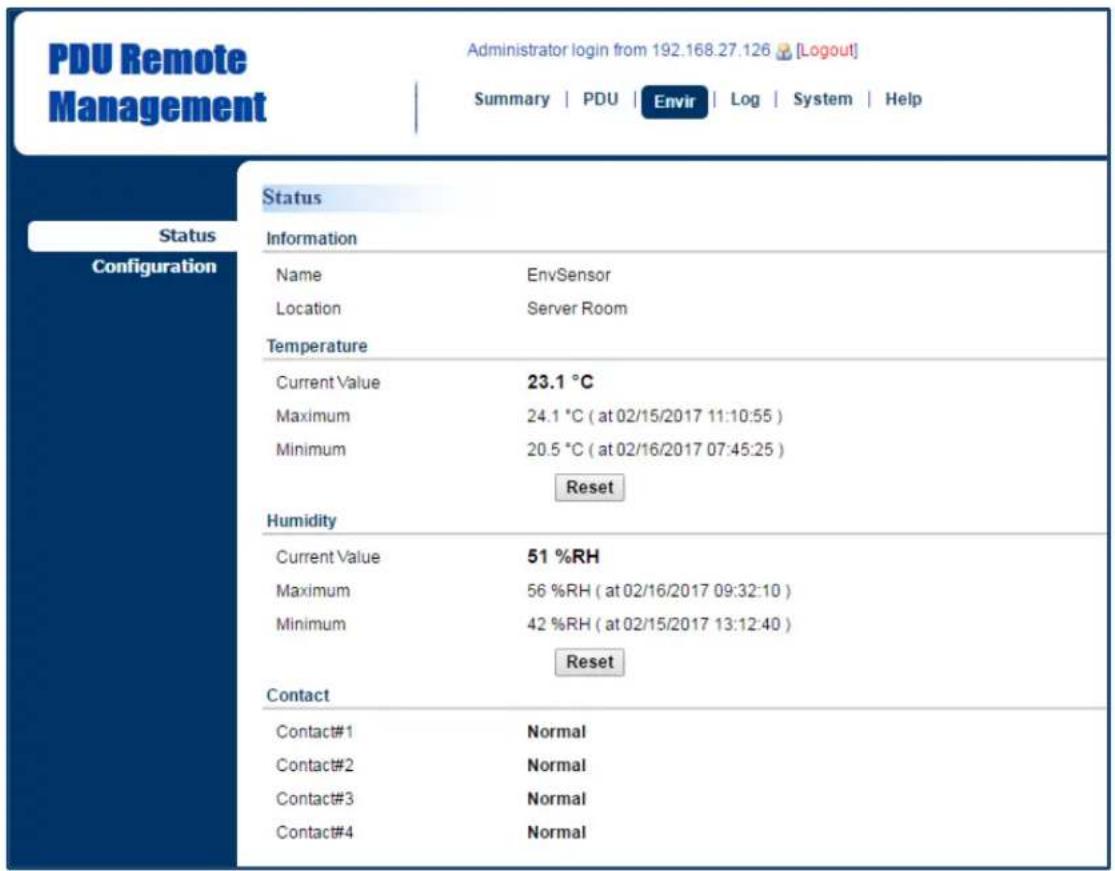
5. Environmental Monitoring
PDU/ATS with CyberPower ENVIROSENSOR can provide remote monitoring of temperature and humidity in a server closet and/or datacenter. You can set temperature and humidity threshold for event action warning. See Envir Tab > Status & Envir Tab > Configuration. Note that Envir Tab only appears when an ENVIROSENSOR is connected to the PDU/ATS.
Envir Tab > Status
text_image
PDU Remote Management Administrator login from 192.168.27.126 [Logout] Summary | PDU | Envir | Log | System | Help Status Information Name EnvSensor Location Server Room Temperature Current Value 23.1 °C Maximum 24.1 °C ( at 02/15/2017 11:10:55 ) Minimum 20.5 °C ( at 02/16/2017 07:45:25 ) Reset Humidity Current Value 51 %RH Maximum 56 %RH ( at 02/16/2017 09:32:10 ) Minimum 42 %RH ( at 02/15/2017 13:12:40 ) Reset Contact Contact#1 Normal Contact#2 Normal Contact#3 Normal Contact#4 Normal| Item | Definition |
| Information | Display the name and location of the ENVIROSENSOR. |
| Temperature | |
| Current Value | The real-time reading of temperature. |
| Maximum | The highest temperature recorded and the time of occurrence. |
| Minimum | The lowest temperature recorded and the time of occurrence. Click Reset to reset the highest and lowest value to zero. |
| Humidity | |
| Current Value | The real-time reading of humidity. |
| Maximum | The highest humidity recorded and the time of occurrence. |
| Minimum | The lowest humidity recorded and the time of occurrence.Click Reset to reset the highest and lowest value to zero. |
| Contact | Display the current status of each input dry contact relay. |
Envir Tab > Configuration

text_image
PDU Remote Management Administrator login from 192 168 25:32 [Logout] Summary | PDU | Envir | Log | System | Help Status Configuration Configuration Information Name EnvSensor Location Server Room Temperature High Threshold 32 °C [1-70] Low Threshold 15 °C [1-70] Hysteresis 2 °C [1-10] Rate of Change 10 °C per 5 minutes [1-70] Unit °C ▼ Humidity High Threshold 80 %RH [10-90] Low Threshold 20 %RH [10-90] Hysteresis 5 %RH [1-20] Rate of Change 20 %RH per 5 minutes [1-80] Contact #1 Name & State Contact#1 Normally Open ▼ #2 Name & State Contact#2 Normally Open ▼ #3 Name & State Contact#3 Normally Open ▼ #4 Name & State Contact#4 Normally Open ▼ Apply Reset| Item | Definition |
| Information | |
| Name | The name entered by user to identify the ENVIROSENSOR. |
| Location | The location of the ENVIROSENSOR, entered by the user. |
| Temperature | |
| High Threshold | Set the highest temperature value for a high temperature warning. |
| Low Threshold | Set the lowest temperature value for a low temperature warning. |
| Hysteresis | The point where the environmental state changes from abnormal to normal and users receive a clearing event notification. The function of Hysteresis is to avoid receiving multiple event notifications.*For high threshold, the point is the threshold minus the Hysteresis value; for low threshold, the point is the threshold plus the Hysteresis value.For example: The high threshold is 32°C, and hysteresis is 2°C. The temperature rises to 33°C, you will get a warning. Then it goes down to 31°C and up to 33°C repeatedly. No clearing events and warnings will occur while the temperature readings are within the Hysteresis. You will not get a clearing event until it drops to 30°C. |
| Rate of Change | Define the abnormal change of temperature per 5 minutes.For example: The current temperature is 23°C, and rate of change is 10°C. If it goes up to 33°C or down to 13°C within 5 minutes, you will get a warning. |
| Unit | Select the unit of temperature. |
| Humidity | |
| High Threshold | Set the highest humidity value for a high humidity warning. |
| Low Threshold | Set the lowest humidity value for a low humidity warning. |
| Hysteresis | Same as Hysteresis under temperature. |
| Rate of Change | Same as Hysteresis under temperature. |
| Contact | Enter the name of each input dry contact relay and use the dropdown menu to define the normal status of each one. |
Advanced Power Management
Remote Monitoring
Users can see real-time readings of PDU/ATS vitals such as device load, power consumption, and outlet status for an overview of current PDU/ATS status. See Summary Tab, PDU/ATS Tab > Status, and PDU/ATS Tab > Status > Outlet.
Summary Tab

text_image
PDU Remote Management Administrator login from 192 168 25 28 [Logout] Summary | PDU | Envir | Log | System | Help Summary Host Current Condition PDU is normal Environment sensor is normal PDU Status Dev Load 0.00 A Outlet 1 2 3 4 5 6 7 8 System Data Name PDU81001 Location Server Room Contact Administrator Rating 12A Uptime 4day. 5hr. 17min. 10sec. Time 2017/07/24 20:51:34 Envir Status Temperature 29.5°C Humidity 43%RH Envir Data Name Env Sensor Location Server Room Recent Device Events Time Events 2017/07/20 16:08:29 Daisy chain new guest added; PDU81001 (SN: 123456789022) is Guest #1
text_image
ATS Remote Management Administrator login from 192 166.210.139 [Logout] Summary | ATS | Log | System | Help Summary Current Condition i ATS is normal. ATS Status selected Source A Dev Load 0.00 A Outlet 1 2 3 4 5 6 7 8 9 10 System Data Name PDU44002 Location Server Room Contact Administrator Uptime 10hr. 25min. 59sec. Time 2024-03-05 18:28:22 Rating Current 16A Rating Voltage 100-120 V| Item | Definition |
| HOST/GUEST# | Select the role of PDU/ATS (HOST or GUEST#) if PDU/ATSs are daisy chained. Up to 3 GUEST PDU/ATSs can connect to 1 HOST PDU/ATS. |
| Current Condition | Operating condition of the PDU/ATS and ENVIROSENSOR. |
| PDU/ATS Status | |
| Dev Load | Total load current of all connected devices, measured in Amps. |
| Outlet | The on/off status of each outlet. The green light icon indicates that the outlet is on and providing power. This light will go off when the outlet turns off. Outlet Tooltip Function: move the cursor to an individual outlet, Outlet name and its ON/OFF status will be shown. |
| System Data | |
| Name | The name of the PDU/ATS. For configuration, see System Tab > General > Identification. |
| Location | The location of the PDU/ATS. For configuration, see System Tab > General > Identification. |
| Contact | The person accountable for the maintenance of the PDU/ATS. For configuration, see System Tab > General > Identification. |
| Rating | UL current rating of the PDU/ATS, measured in Amps. |
| Uptime | The amount of time the system has been working for since it was last restarted. |
| Time | System time of the PDU/ATS. For configuration, see System Tab > General > Time. |
| Envir Status | |
| Temperature | Display temperature reading when the ENVIROSENSOR is connected to the PDU/ATS. |
| Humidity | Display humidity reading when the ENVIROSENSOR is connected to the PDU/ATS. |
| Envir Data | |
| Name | The name of the ENVIROSENSOR. For configuration, see Envir Tab > Configuration. |
| Location | The location of the ENVIROSENSOR. For configuration, see Envir Tab > Configuration. |
| Recent Device Events | A list of the five most recent device events. All events are related t configuration changes. |
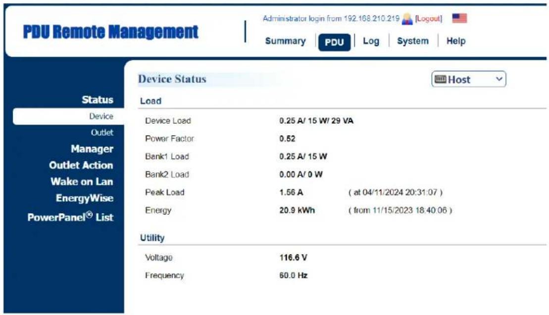
PDU Tab > Status > Device
text_image
PDU Remote Management Administrator login from 192.168.210.219 [Logout] Summary PDU Log System Help Status Device Status Host Load Device Load 0.25 A/ 15 W/ 29 VA Power Factor 0.52 Bank1 Load 0.25 A/ 15 W Bank2 Load 0.00 A/ 0 W Peak Load 1.56 A ( at 04/11/2024 20:31:07 ) Energy 20.9 kWh ( from 11/15/2023 18:40:06 ) Utility Voltage 116.6 V Frequency 60.0 HzATS Tab > Status > Device
| ATS Remote Management | Administrator login from 192 168.210 139 [Logout] Summary | ATS | Log | System | Help | ||
| Status Device Outlet Manager Outlet Action Event Counts Wake on Lan PowerPanel® List | Device Status | ||
| Source | |||
| Selected Source | Source A | ||
| Preferred Source | Source A | ||
| Source Voltage (A/B) | 120.7 /120.8 V | ||
| Source Frequency (A/B) | 60.0 /60.0 Hz | ||
| Source Status (A/B) | OK / OK | ||
| Phase Synchronization | Yes | ||
| Load | |||
| Device Load | 0.00 A/ 0 W/ 0 VA | ||
| Power Factor | ---- | ||
| Peak Load | 0.25 A | (at 2023-11-23 14:23:14 ) | |
| Energy | 0.0 kWh | (from 2023-08-07 15:35:15 ) | |
| Device | |||
| Power Supply Status | OK | ||
| Item | Definition |
| HOST/GUEST# | Select the role of PDU/ATS (HOST or GUEST#) if PDU/ATSs are daisy chained. Up to 3 GUEST PDU/ATS s can connect to 1 HOST PDU/ATS. |
| Source Status (For ATS Series Only) | |
| Selected Source | Source currently supplying power to load. |
| Preferred Source | Source the ATS will switch over to when both sources are acceptable. |
| Source Voltage | Input voltage of the source. |
| Source Frequency | Frequency of the source. |
| Source Status | Status that indicates if the source is OK. |
| Phase Synchronization | Status that indicates if source A and B are in phase. |
| Load | |
| Device Load | Load current of the connected device(s), measured in Amps.Load power of the connected device(s), measured in Kilowatts and Kilovolt-Amps. |
| Bank Load* | Load current of the bank, measured in Amps. |
| Power Factor | Power factor of the connected device(s). |
| Peak Load | Maximum load current recorded and the time of occurrence.Users can reset the value to zero at Power Restore in PDU/ATS Tab > Manager > Device. |
| Energy | Total energy consumed by the connected device(s) from the reset date, measured in kWh.Users can reset the value to zero at Power Restore in PDU/ATS Tab > Manager > Device. |
| Utility | |
| Voltage | Voltage of the utility power. |
| Frequency | Frequency of the utility power. |
*Only available in select models.
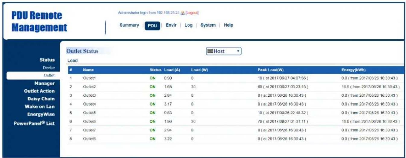
PDU/ATS Tab > Status > Outlet\*
text_image
PDU Remote Management Administrator login from 192 158 25 20 [Logout] Summary | PDU | Envir | Log | System | Help Status Device Outlet Manager Outlet Action Daisy Chain Wake on Lan EnergyWise PowerPanel® List Outlet Status Host LoadName Status Load (A) Load (W) Peak Load(W) Energy(kWh)
1 Outlet1 ON 0.90 0 10 ( at 2017/06/27 04:07:56 ) 0.0 ( from 2017/06/26 16:30:43 ) 2 Outlet2 ON 1.68 30 60 ( at 2017/06/27 03:23:15 ) 16.5 ( from 2017/06/26 16:30:43 ) 3 Outlet3 ON 2.84 0 0 ( at 2017/06/26 16:30:43 ) 0.0 ( from 2017/06/26 16:30:43 ) 4 Outlet4 ON 3.17 0 0 ( at 2017/06/26 16:30:43 ) 0.0 ( from 2017/06/26 16:30:43 ) 5 Outlet5 ON 0.83 0 10 ( at 2017/06/26 22:48:32 ) 0.0 ( from 2017/06/26 16:30:43 ) 6 Outlet6 ON 1.96 30 70 ( at 2017/06/27 01:31:11 ) 18.0 ( from 2017/06/26 16:30:43 ) 7 Outlet7 ON 2.94 0 0 ( at 2017/06/26 16:30:43 ) 0.0 ( from 2017/06/26 16:30:43 ) 8 Outlet8 ON 3.22 0 0 ( at 2017/06/26 16:30:43 ) 0.0 ( from 2017/06/26 16:30:43 )*The above Outlet Status Page is available for Switched Metered by Outlet Series, Metered by Outlet Series and Switched Series only.
| Item | Definition |
| HOST/GUEST# | Select the role of PDU/ATS (HOST or GUEST#) if PDU/ATS s are daisy chained. Up to 3 GUEST PDU/ATS s can connect to 1 HOST PDU/ATS. |
| Status | The on/off status of each outlet. |
| Load (A) | Load current of each outlet, measured in Amps. |
| Load (kW) | Load power of each outlet, measured in Kilowatts. |
| Peak Load (kW) | The maximum load current recorded and the time of occurrence. Users can reset the value to zero at Power Restore in PDU/ATS Tab > Manager > Outlet. |
| Energy (kWh) | Total energy consumed by connected equipment of each outlet since the last reset. The reset can be set in PDU/ATS Tab > Manager > Outlet. |
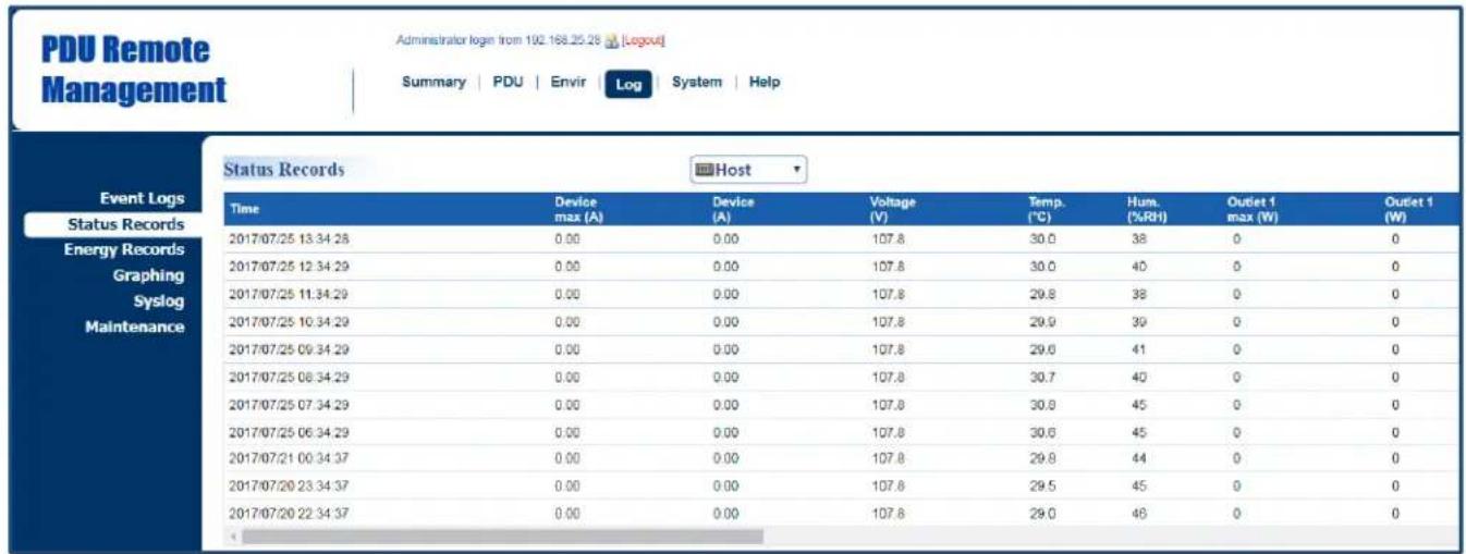
Visible Power Consumption
With comprehensive energy measurement data, users can gain more visibility to the total power usage of a PDU/ATS or the status of source A and B of an ATS, as well as estimate the energy cost and CO2 emissions. The energy-trend report also helps users analyze their power utilization and to review the history of power conditions. See Log Tab > Status Records, Log Tab > Graphing, Log Tab > Energy Records, and Log Tab > Maintenance.
Log Tab > Status Records
text_image
PDU Remote Management Administrator login from 192.168.25.28 [Logout] Summary | PDU | Envir Log System | Help Event Logs Status Records Energy Records Graphing Syslog Maintenance Status Records Host Time Device max (A) Device (A) Voltage (V) Temp. (℃) Hum. (%RH) Outlet 1 max (W) Outlet 1 (W) 2017/07/25 13:34:28 0.00 0.00 107.8 30.0 38 0 0 2017/07/25 12:34:29 0.00 0.00 107.8 30.0 40 0 0 2017/07/25 11:34:29 0.00 0.00 107.8 29.8 38 0 0 2017/07/25 10:34:29 0.00 0.00 107.8 29.9 39 0 0 2017/07/25 09:34:29 0.00 0.00 107.8 29.6 41 0 0 2017/07/25 08:34:29 0.00 0.00 107.8 30.7 40 0 0 2017/07/25 07:34:29 0.00 0.00 107.8 30.8 45 0 0 2017/07/25 06:34:29 0.00 0.00 107.8 30.6 45 0 0 2017/07/21 05:34:37 0.00 0.00 107.8 29.8 44 0 0 2017/07/20 23:34:37 0.00 0.00 107.8 29.5 45 0 0 2017/07/20 22:34:37 0.00 0.00 107.8 29.0 46 0 0| ATS Remote Management | Administrator login from 192.168.210.139 [Logout] | ||||||||
| Summary | ATS | Log | System | Help | |||||
| Event Logs Status Records Energy Records Graphing Syslog Maintenance | Status Records | ||||||||
| Time | SourceA Max(V) | SourceA Min(V) | SourceB Max(V) | SourceB Min(V) | SourceA (Hz) | SourceB (Hz) | Device max (A) | Device (A) | |
| 2024-03-01 14:07:24 | 121.5 | 120.4 | 121.6 | 120.5 | 80.0 | 60.0 | 0.00 | 0.00 | |
| 2024-03-01 14:06:24 | 121.5 | 120.4 | 121.5 | 120.5 | 60.0 | 60.0 | 0.00 | 0.00 | |
| 2024-03-01 14:05:24 | 121.4 | 120.4 | 121.5 | 120.5 | 60.0 | 60.0 | 0.00 | 0.00 | |
| 2024-03-01 14:04:24 | 121.3 | 120.4 | 121.5 | 120.6 | 60.0 | 60.0 | 0.00 | 0.00 | |
| 2024-03-01 14:03:24 | 121.3 | 120.3 | 121.4 | 120.4 | 60.0 | 60.0 | 0.00 | 0.00 | |
| 2024-03-01 14:02:24 | 121.5 | 120.4 | 121.5 | 120.4 | 60.0 | 60.0 | 0.00 | 0.00 | |
| 2024-03-01 14:01:24 | 121.4 | 120.4 | 121.4 | 120.4 | 60.0 | 60.0 | 0.00 | 0.00 | |
| 2024-03-01 14:00:24 | 121.3 | 120.4 | 121.4 | 120.4 | 60.0 | 60.0 | 0.00 | 0.00 | |
| Item | Definition |
| HOST/GUEST# | Select the role of PDU/ATS (HOST or GUEST#) if PDUs/ATS are daisy chained. Up to 3 GUEST PDU/ATSs can connect to 1 HOST PDU/ATS. |
| Source A/B Max (V)* | The maximum voltage of the Source A/B during a specific time interval, measured in Volts. This interval can be set inLog Tab > Maintenance. |
| Source A/B Min (V)* | The minimum voltage of the Source A/B during a specific time interval, measured in Volts. This interval can be set inLog Tab > Maintenance. |
| Source A/B (Hz)* | Frequency of the Source A/B. |
| Device Max (A) | The maximum load current of the connected device(s) or bank during a specific time interval, measured in Amps. This interval can be set inLog Tab > Maintenance. |
| Device (A) | Load current of the connected device(s) or bank, measured in Amps. |
| Dev. (W) | Watt of the connected devices(s) or bank, measured in Watts. |
| Voltage (V) | Voltage of the utility power. |
| ENV# Temp. (°C) | Temperature reading when the SNEV001# is connected to the PDU/ATS. |
| ENV# Hum. (%RH) | Humidity reading when the SNEV001# is connected to the PDU/ATS. |
| Temp. (°C) | Temperature reading when the ENVIROSENSOR is connected to the PDU/ATS. |
| Hum. (%RH) | Humidity reading when the ENVIROSENSOR is connected to the PDU/ATS. |
| Outlet # Max (kW)** | The maximum load power of a specific outlet during a specific time interval, measured in Kilowatts. This interval can be set inLog Tab > Maintenance. |
| Outlet # (kW)** | Load power of a specific outlet, measured in Kilowatts. |
*For ATS Series only
**For Switched Metered by Outlet Series and Metered by Outlet Series only.
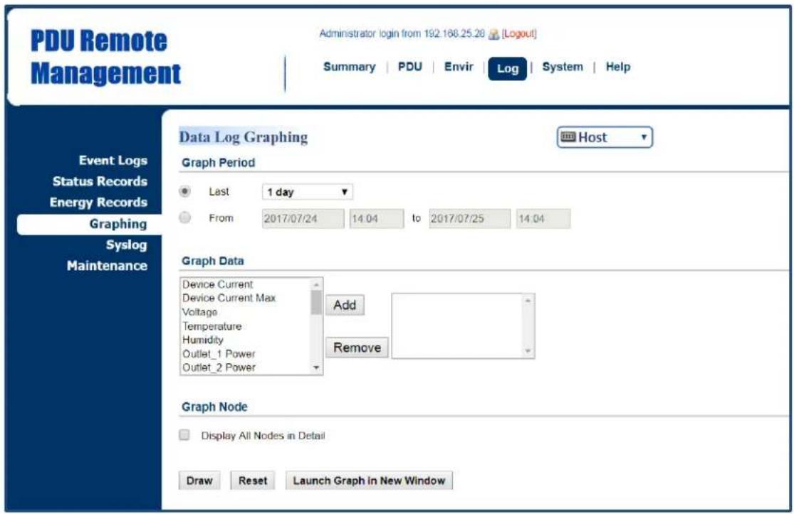
Log Tab > Graphing
text_image
PDU Remote Management Administrator login from 192.168.25.20 [Logout] Summary | PDU | Envir | Log | System | Help Event Logs Status Records Energy Records Graphing Syslog Maintenance Data Log Graphing Host Graph Period Last 1 day From 2017/07/24 14.04 to 2017/07/25 14.04 Graph Data Device Current Device Current Max Voltage Temperature Humidity Outlet_1 Power Outlet_2 Power Add Remove Graph Node Display All Nodes in Detail Draw Reset Launch Graph in New Window| Item | Definition |
| HOST/GUEST# | Select the role of PDU/ATS (HOST or GUEST#) if PDU/ATSs are daisy chained. Up to 3 GUEST PDU/ATSs can connect to 1 HOST PDU/ATS. |
| Graph Period | The time period is used to create a retroactive graph of the status records. A large time period will require more time to render the graph. |
| Graph Data | The data used to create a graph of the status records. Up to five data points can be selected. A large number of data selected will require more time to render the graph. |
| Graph Node | Select the Display All Nodes in Detail option to display the selected data points along the graph. When the cursor is moved to an individual data point, information about that point will be shown. If this option is not selected, the graph will show only the line (without the points), so less time is needed to render. |
| Draw | A graph of the status records will be created. |
| Reset | Reset the Graph Period to default (1 day). |
| Launch Graph in New Window | A detailed view of the graph opens in a new browser window. |
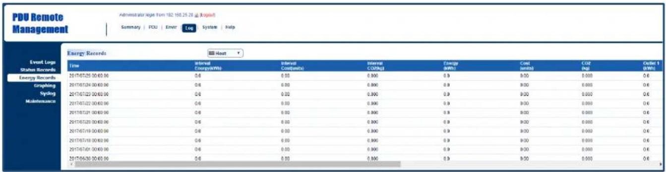
Log Tab > Energy Records
text_image
PDU Remote Management Administrator loge Tom 192.160.25.28 @ (logpat) Summary | PDU | Envir | Log | System | Help Event Log Status Records Energy Records Graphing Sviking Maintenance Energy Records Host Time internal Energy(MWh) Internal Cost(units) Internal CO2(kg) Energy (MWh) Cost (units) CO2 (Pg) Outlet 1 (MWh) 2017/07/25 00:00:00 0.6 0.00 0.000 0.9 0.00 0.000 0.6 2017/07/24 00:00:00 0.6 0.00 0.000 0.9 0.00 0.000 0.6 2017/07/23 00:00:00 0.6 0.00 0.000 0.9 9.00 0.000 0.6 2017/07/22 00:00:00 0.6 0.00 0.000 0.9 9.00 0.000 0.6 2017/07/21 00:00:00 0.6 8.00 8.000 8.9 8.00 8.000 8.6 2017/07/20 00:00:00 0.6 8.00 8.00C 8.9 9.00 8.888 8.6 2017/07/19 00:00:00 0.6 8.55 8.55C 8.9 9.55 8.888 8.6 2017/07/18 00:55:55C 8.6 8.55 8.55C 8.9 9.55 8.888 8.6 2017/07/17 19:35:35C 8.6 8.55 8.55C 8.9 9.55 8.888 8.6 2017/16/36 33:33:33C| Item | Definition |
| HOST/GUEST# | Select the role of PDU/ATS (HOST or GUEST#) if PDU/ATS s are daisy chained. Up to 3 GUEST PDU/ATS s can connect to 1 HOST PDU/ATS. |
| Interval Energy (kWh) | Energy consumed by connected device(s) during a specific time interval, measured in kWh. This interval can be set in Log Tab > Maintenance. |
| Interval Cost (units) | Cost of the energy consumed by the connected device(s) during a specific time interval, equal to Electricity Rate multiplied by Interval Energy. The interval and electricity rate can be set in Log Tab > Maintenance. |
| Interval CO2 (kg) | Equivalent CO2 emission of the connected device(s) during a specific time interval, equal to CO2 Emissions multiplied by Interval Energy. The interval and CO2 emissions can be set in Log Tab > Maintenance. |
| Energy (kWh) | Accumulated Interval Energy since the last reset. The reset can be set in Log Tab > Maintenance. |
| Cost (units) | Accumulated Interval Cost since the last reset. The reset can be set in Log Tab > Maintenance. |
| CO2 (kg) | Accumulated Interval CO2 since the last reset. The reset can be set in Log Tab > Maintenance. |
| Outlet # (kWh)* | Accumulated Interval Energy of a specific outlet since the last reset. The reset can be set in Log Tab > Maintenance. |
*For Switched Metered by Outlet Series and Metered by Outlet Series only.
Log Tab > Maintenance

text_image
PDU Remote Management Administrator login from 192.168.25.28 [Logout] Summary | PDU | Envir | Log | System | Help Event Logs Status Records Energy Records Graphing Syslog Maintenance Maintenance Event Logs Clear All Logs No Yes, right now. The Number of Events 111 / 1024 Save Event Logs Save Status Records Recording Interval 1 hour Clear All Records No Yes, right now Remaining Time 56day 11hour / 85day 8hour Save Status Records Host Save Energy Records Recording Interval one day Clear All Records No Yes, right now Electricity Rate 3.00 units / kWh [0.00-600] CO2 Emissions 0.60 kg / kWh [0.00-600] Save Energy Records Host Save Apply Reset| Item | Definition |
| Event Logs | |
| Clear All Logs | Clear the existing event logs. |
| The Number of Events | The number of the existing event logs and the maximum number of the event logs that can be recorded. Once the maximum number is reached, new events overwrite oldest events in memory. |
| Save Event Logs | Save the existing event logs as a text file. |
| Status Records | |
| Recording Interval | The frequency to record the status data.A smaller interval will provide more recordings, but the recordings are overwritten in a shorter period of time. A larger interval will provide fewer recordings, but the recordings are overwritten in a longer period of time. |
| Clear All Records | Clear the existing status records. |
| Remaining Time | The time that records have been kept. A smaller recording interval leads to less remaining time while a larger recording interval leads to more remaining time. Once the maximum number is reached, new status records overwrite oldest status records in memory. |
| Save Status Records | Save the status records as a text file. |
| Energy Records | |
| Recording Interval | The frequency to record the energy data. |
| Clear All Records | Clear the existing energy records. |
| Electricity Rate | The cost (units) of energy per unit of energy consumed (kWh). Unit is a monetary value. |
| CO2 Emissions | The equivalent CO2 emission (kg) per unit of energy consumed (kWh). |
| Save Energy Records | Save the existing energy records as a text file. |
Event Logging
Users can view all the events, including log in/out records and configuration changes. The timestamp is recorded in a 24-hour format. See Log Tab > Syslog and Log Tab > Event Logs. For event logs, Users can clear the existing event logs in Log Tab > Maintenance
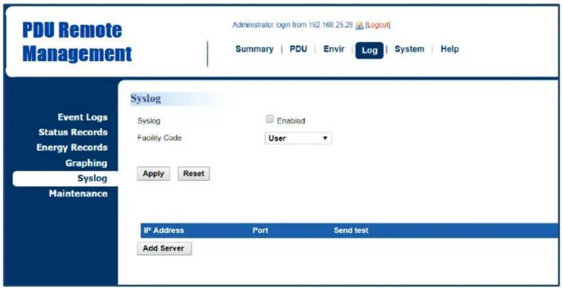
Log Tab > Syslog
text_image
PDU Remote Management Administrator login from 192.168.25.28 (Logout) Summary | PDU | Envir | Log | System | Help Event Logs Status Records Energy Records Graphing Syslog Maintenance Syslog Syslog Enabled Facility Code User Apply Reset IP Address Port Send test Add Server| Item | Definition |
| Syslog | Check this box to enable Syslog function. |
| Facility Code | Classify syslog message |
Click Add Server to enter Syslog Server Page.
Syslog Server Page

text_image
PDU Remote Management Administrator login from 192.168.25.28 [Logout] Summary | PDU | Envir | Log | System | Help Event Logs Status Records Energy Records Graphing Syslog Maintenance Syslog Server Server IP 192 168 26.76 Server Port 514 Apply Reset| Item | Definition |
| Server IP | The IP address of Syslog server. |
| Server Port | The port number that Syslog server uses to communicate. |
Logs Tab > Event Logs
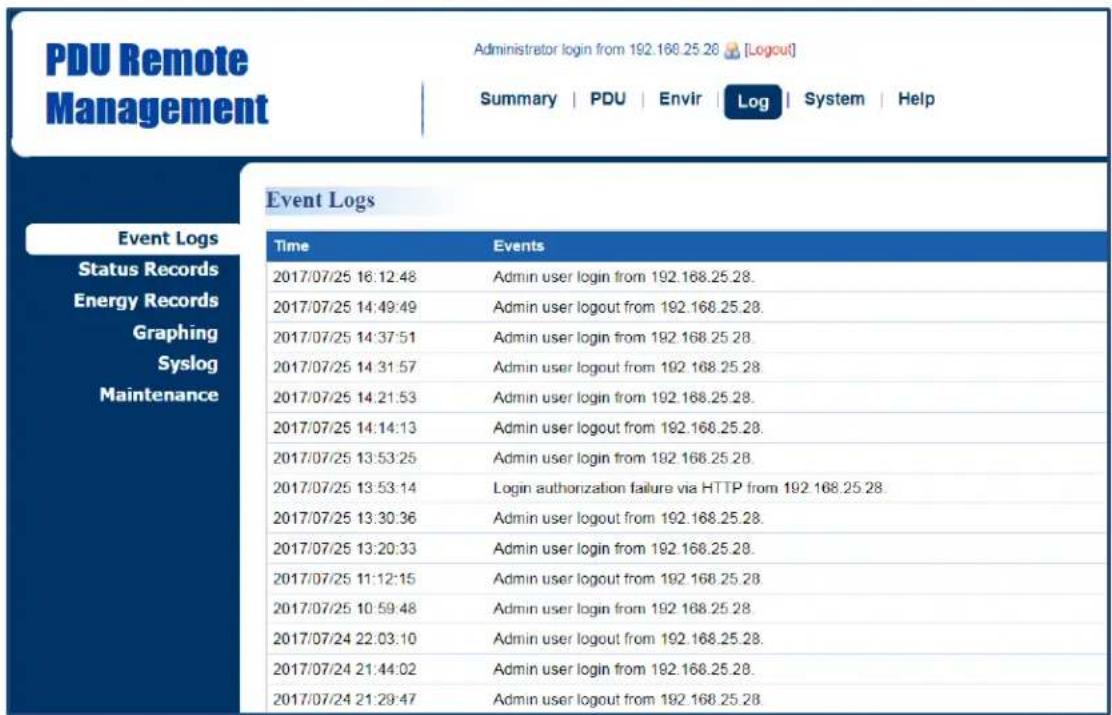
text_image
PDU Remote Management Administrator login from 192.168.25.28 [Logout] Summary | PDU | Envir | Log | System | Help Event Logs Event Logs Status Records Energy Records Graphing Syslog Maintenance Time Events 2017/07/25 16:12:48 Admin user login from 192.168.25.28. 2017/07/25 14:49:49 Admin user logout from 192.168.25.28. 2017/07/25 14:37:51 Admin user login from 192.168.25.28. 2017/07/25 14:31:57 Admin user logout from 192.168.25.28. 2017/07/25 14:21:53 Admin user login from 192.168.25.28. 2017/07/25 14:14:13 Admin user logout from 192.168.25.28. 2017/07/25 13:53:25 Admin user login from 192.168.25.28. 2017/07/25 13:53:14 Login authorization failure via HTTP from 192.168.25.28. 2017/07/25 13:30:36 Admin user logout from 192.168.25.28. 2017/07/25 13:20:33 Admin user login from 192.168.25.28. 2017/07/25 11:12:15 Admin user logout from 192.168.25.28. 2017/07/25 10:59:48 Admin user login from 192.168.25.28. 2017/07/24 22:03:10 Admin user logout from 192.168.25.28. 2017/07/24 21:44:02 Admin user login from 192.168.25.28. 2017/07/24 21:29:47 Admin user logout from 192.168.25.28Power Protection
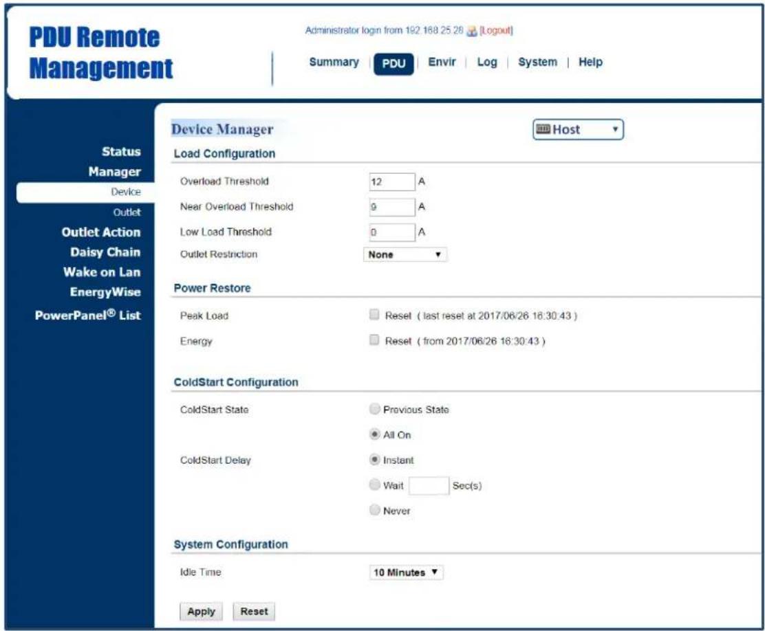
The configurable load threshold can be set to prevent an overload condition. ColdStart and system configurations are also offered for different user needs. See PDU/ATS Tab > Device Manager.
PDU/ATS Tab > Manager > Device
text_image
PDU Remote Management Administrator login from 192.168.25.28 [Logout] Summary | PDU | Envir | Log | System | Help Status Manager Device Outlet Outlet Action Daisy Chain Wake on Lan EnergyWise PowerPanel® List Device Manager Host Load Configuration Overload Threshold 12 A Near Overload Threshold 9 A Low Load Threshold 0 A Outlet Restriction None ▼ Power Restore Peak Load Reset ( last reset at 2017/06/26 16:30:43 ) Energy Reset ( from 2017/06/26 16:30:43 ) ColdStart Configuration ColdStart State Previous State All On ColdStart Delay Instant Wait Sec(s) Never System Configuration Idle Time 10 Minutes ▼ Apply Reset| Item | Definition |
| HOST/GUEST# | Select the role of PDU/ATS (HOST or GUEST#) if PDU/ATSs are daisy chained. Up to 3 GUEST PDU/ATS s can connect to 1 HOST PDU/ATS. |
| Load Configuration | |
| Overload Threshold | Set the value for the total current on the PDU/ATS that will signal an overload warning. Must be higher than Near Overload Threshold and equal to or lower than the PDU/ATS Rating in the Summary Tab. |
| Near Overload Threshold | Set the value for the total current on the PDU/ATS that will signal a near overload warning. Must be between Overload Threshold and Low Load Threshold. |
| Low Load Threshold | Set the value for the total current on the PDU/ATS that will signal a low load warning. Must be lower than Near Overload Threshold. |
| Outlet Restriction*** | When load current exceeds the corresponding threshold, no outlets will be allowed to turn on.*None: Users can turn on an outlet even if the device is in Near Overload or Overload state.*On Near Overload: Users cannot turn on an outlet when the device is in Near Overload or Overload state.*On Overload: Users cannot turn on an outlet when the device is in Overload state. |
| Power Restore | |
| Peak Load | Reset the peak load to zero. |
| Energy | Reset the energy to zero. |
| ColdStart Configuration | |
| ColdStart State | *Previous State: Outlets will return to the same state (on or off) they were in prior to the PDU/ATS turning off. The ColdStart Delay setting will apply when the PDU/ATS resumes power.*All On: All outlets will turn on when power is restored to the PDU/ATS. |
| ColdStart Delay | *Instant: Outlets will be turned on immediately when power is restored to the PDU/ATS.*Wait: Outlets will be turned on according to each outlet(s) Power On Delay after ColdStart Delay Wait when power is restored to the PDU/ATS.*Never: Outlets will never turned on when power is restored to the PDU/ATS. |
| System Configuration | |
| Idle Time | The PDU/ATS LCD screen will turn off automatically after it remains idle for the selected period of time. |
***For some models, the Outlet Restriction only shows in the Bank Manager Page.
Source Configuration
Users can select the preferred source as the primary input. When the primary input fails, the ATS will switch to the secondary one to ensure continuous operation. Frequency Parameters and Voltage Parameters configurations are also offered for user needs. See ATS Tab > Source Manager. (For ATS Series only.)
ATS Tab > Manager > Source

text_image
ATS Remote Management Administrator login from 192.168.210.139 [Logout] Summary | ATS | Log | System | Help Status Manager Source Device Outlet Outlet Action Event Counts Wake on Lan PowerPanel® List Source Manager Source Setting Preferred Source ● Source A ○ Source B ○ None Frequency Parameters Configuration Nominal Frequency 60 Hz Frequency Deviation ±1▼ Hz Voltage Parameters Configuration Sensitivity High▼ Nominal Voltage 110▼ V Voltage Transfer Range ● Wide ±20 V [6-20] ○ Medium ±12 V [6-20] ○ Narrow ±8 V [6-20] Apply Reset| Item | Definition |
| HOST/GUEST# | Select the role of PDU/ATS (HOST or GUEST#) if PDU/ATSs are daisy chained. Up to 3 GUEST PDU/ATS s can connect to 1 HOST PDU/ATS. |
| Source | |
| Preferred Source | Source the ATS will switch over to when both sources are acceptable. |
| Frequency | |
| Frequency Deviation | The range of acceptable frequency fluctuation. |
| Voltage | |
| Sensitivity | *High sensitivity means the ATS will switch over to the alternate source in response to small voltage changes.*Medium sensitivity means the ATS will switch over to the alternate source in response to medium voltage changes.*Low sensitivity means the ATS will switch over to the alternate source in response to Large voltage changes. |
| Nominal Voltage | Nominal source voltage setting for the device. |
| Voltage Transfer Range | The acceptable voltage range of source. When the source voltage is out of the voltage transfer range, the ATS will switch over to the alternate source.Options include Wide, Medium, and Narrow. The Wide value must be greater than the Medium value, and The Medium value must be greater than the Narrow value. |
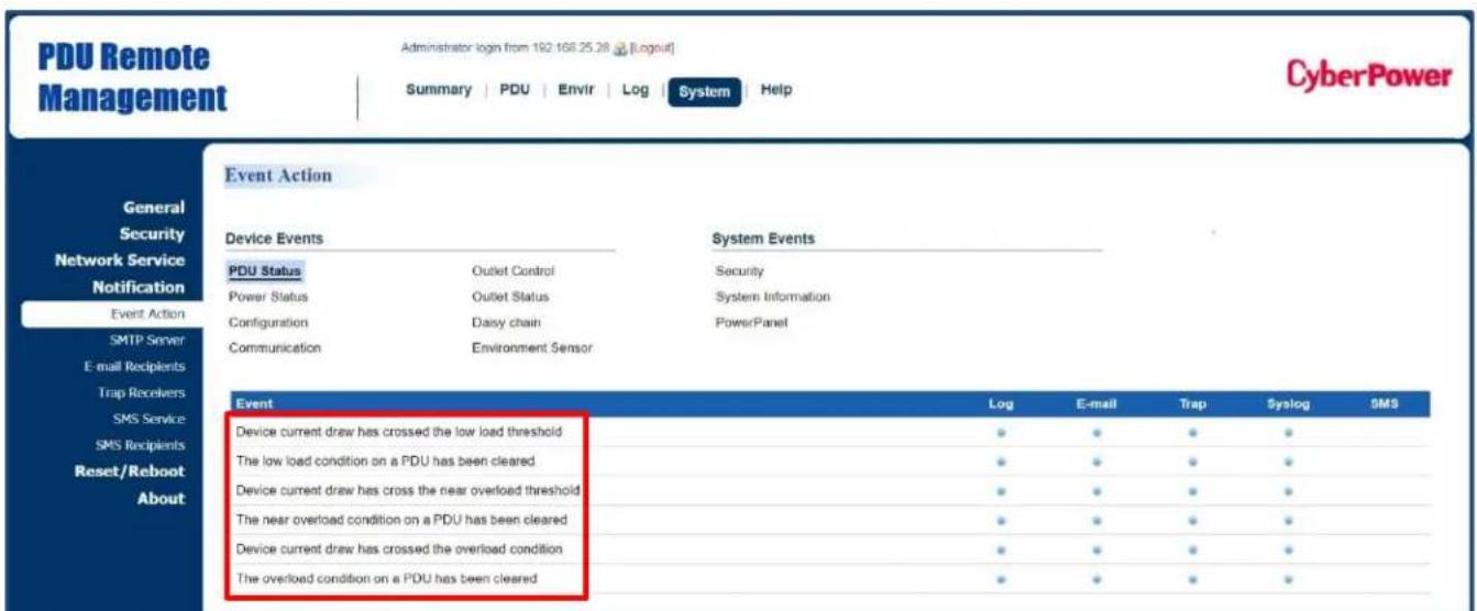
Event Action Notification
Users decide the event actions for which they receive notifications. When a certain event happens, an automatic notification will be sent to users so that they can make timely decisions to prevent potential problems. See System Tab > Notification.
System Tab > Notification > Event Action
text_image
PDU Remote Management Administrator login from 192.168.25.28 [Logout] Summary | PDU | Envir | Log | System | Help CyberPower Event Action General Security Network Service Notification Event Action SMTP Server E-mail Recipients Trap Recivers SMS Service SMS Recipients Reset/Reboot About Device Events System Events PDU Status Outlet Control Security Power Status Outlet Status System Information Configuration Daisy chain PowerPanel Communication Environment Sensor Event Log E-mail Trap Syslog SMS Device current draw has crossed the low load threshold ● ● ● ● The low load condition on a PDU has been cleared ● ● ● ● Device current draw has crossed the near overload threshold ● ● ● ● The near overload condition on a PDU has been cleared ● ● ● ● Device current draw has crossed the overload condition ● ● ● ● The overload condition on a PDU has been cleared ● ● ● ●Click the Event field to enter the Event Action Page.
Event Action Page
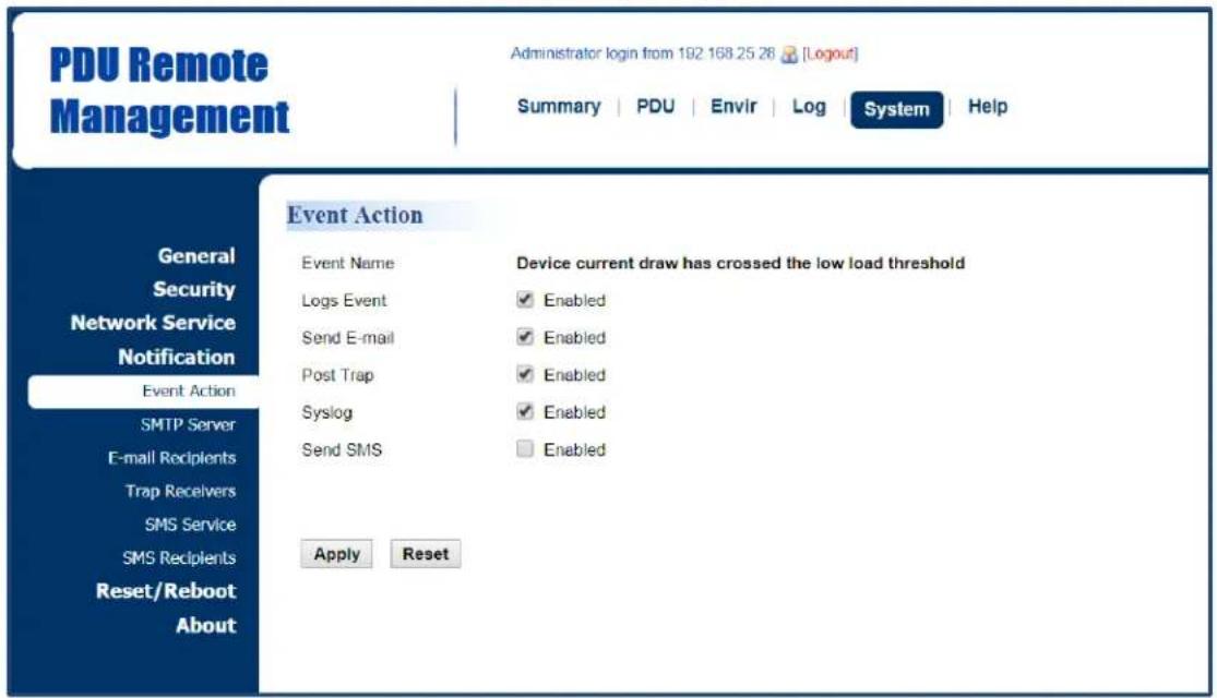
text_image
PDU Remote Management Administrator login from 192 168 25 28 [Logout] Summary | PDU | Envir | Log | System | Help Event Action General Security Network Service Notification Event Action SMTP Server E-mail Recipients Trap Receivers SMS Service SMS Recipients Reset/Reboot About Event Name Device current draw has crossed the low load threshold Logs Event Enabled Send E-mail Enabled Post Trap Enabled Syslog Enabled Send SMS Enabled Apply ResetThe Event Action Page enables users to modify the notification method.
| Item | Definition |
| Logs Event | Record the device event in the Event Logs. |
| Send E-mail | Send an email to a specific user.An available SMTP server is necessary. |
| Post Trap | Send a SNMP trap to a specific IP address. |
| Syslog | Record the device event in Syslog server. |
| Send SMS | Send a short message to a specific mobile phone number.An available Short Message Service (SMS) provider is needed. |
Event Action Recipient Settings
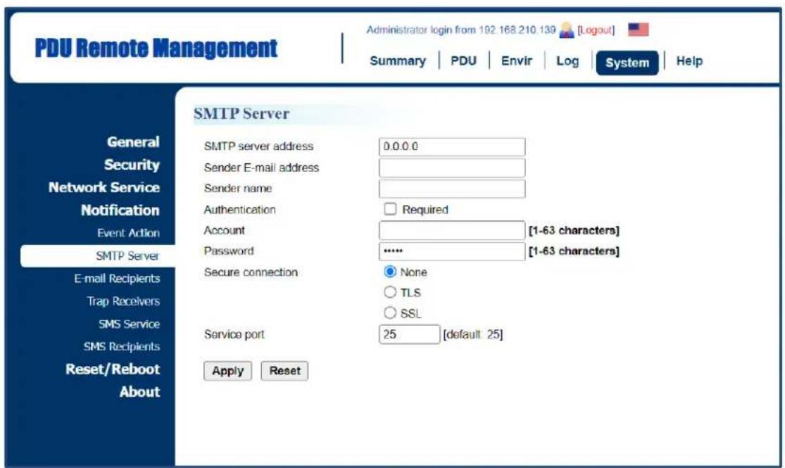
1. E-mail Notification
Set the proper SMTP server settings so that users can receive an email when a specific event occurs. See System Tab > Notification > SMTP Server.
System Tab > Notification > SMTP Server
text_image
PDU Remote Management Administrator login from 192.168.210.139 [Logout] Summary | PDU | Envir | Log | System | Help SMTP Server General Security Network Service Notification Event Action SMTP Server E-mail Recipients Trap Receivers SMS Service SMS Recipients Reset/Reboot About SMTP server address 0.0.0.0 Sender E-mail address Sender name Authentication Required Account [1-63 characters] Password ***** [1-63 characters] Secure connection None TLS SSL Service port 25 [default 25] Apply Reset| Item | Definition |
| SMTP server address | The IP or host Name of SMTP server used to notify users by e-mail. |
| Sender E-mail Address | The From field shown in the e-mail message. |
| Sender Name | The name of the sender. |
| Authentication | Select this option if the SMTP server requires Authentication. |
| User Name | Account used for Authentication. |
| Password | Password used for Authentication. |
| Secure connection | Enable/Disable TLS or SSL to encrypt the SMTP connection. |
| Service Port | The port number that the PDU uses to communicate with SMTP server. |
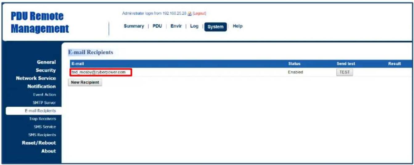
Users can set up to five e-mail recipients in designated email address format.
See System > Notification > E-mail Recipients.
System > Notification > E-mail Recipients
text_image
PDU Remote Management Administrator login from 192.168.25.28 [Logout] Summary | PDU | Envir | Log | System Help E-mail Recipients E-mail Status Send test Result ted_mosby@cyberpower.com Enabled TEST New Recipient| Item | Definition |
| Click the e-mail address of the recipient to enter the Configure E-mail Recipient Page. Users can modify the e-mail address, change its status, check test result, and delete an existing recipient. | |
| TEST | Click this button to check if the SMTP setting and the email recipients are set correctly. |
| New Recipient | Click this button to enter the Add New E-mail Recipient Page. Users can add a new recipient. |
Configure E-mail Recipient Page

text_image
PDU Remote Management Administrator login from 192.168.25.28 [Logout] Summary | PDU | Envir | Log | System | Help Configure E-mail Recipient Activate ✓ Enabled E-mail led_mosby@cyberpower.com Apply Reset Delete General Security Network Service Notification Event Action SMTP Server E-mail Recipients Trap Receivers SMS Service SMS Recipients Reset/Reboot AboutAdd New E-mail Recipient Page
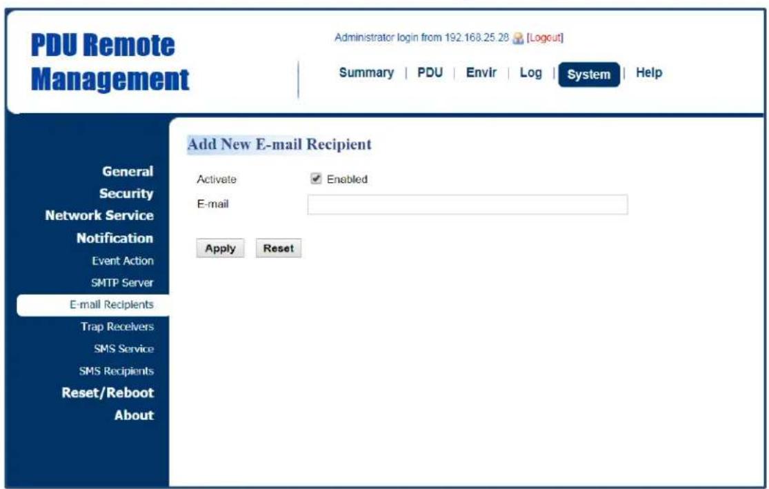
text_image
PDU Remote Management Administrator login from 192.168.25.28 [Logout] Summary | PDU | Envir | Log | System | Help Add New E-mail Recipient General Security Network Service Notification Event Action SMTP Server E-mail Recipients Trap Recivers SMS Service SMS Recipients Reset/Reboot About Activate ✓ Enabled E-mail Apply Reset2. SNMP Trap Notification
Set up to 10 SNMP trap receivers to be notified when an event occurs. See System >Notification > Trap Receivers.
System > Notification > Trap Receivers

text_image
PDU Remote Management Administrator login from 102.168.25.28 [Logout] Summary | PDU | Envir | Log | System | Help CyberPower Trap Receivers General Security Network Service Notification Event Action SMTP Server E-mail Recipients Trap Receivers SMS Service SMS Recipients Reset/Reboot About Trap Name Enabled SNMPv1 0.0.0.0 New Receiver Community/ User Name public Send test TEST| Item | Definition |
| Name | Click on the trap name to enter the Configure Trap Receiver Page.Users can modify or delete an existing receiver. |
| TEST | Click this button to check if the trap can be sent. |
| New Receiver | Click this button to enter the Add New Trap Receiver Page. Users can add a new recipient. |
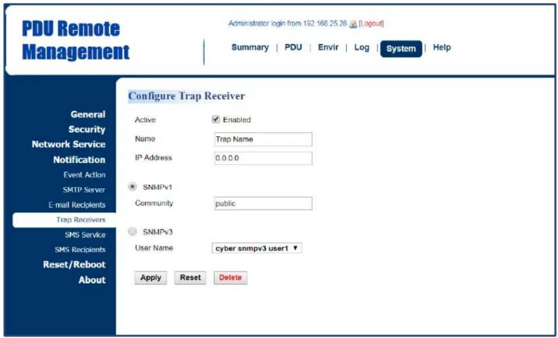
Configure Trap Receiver Page
text_image
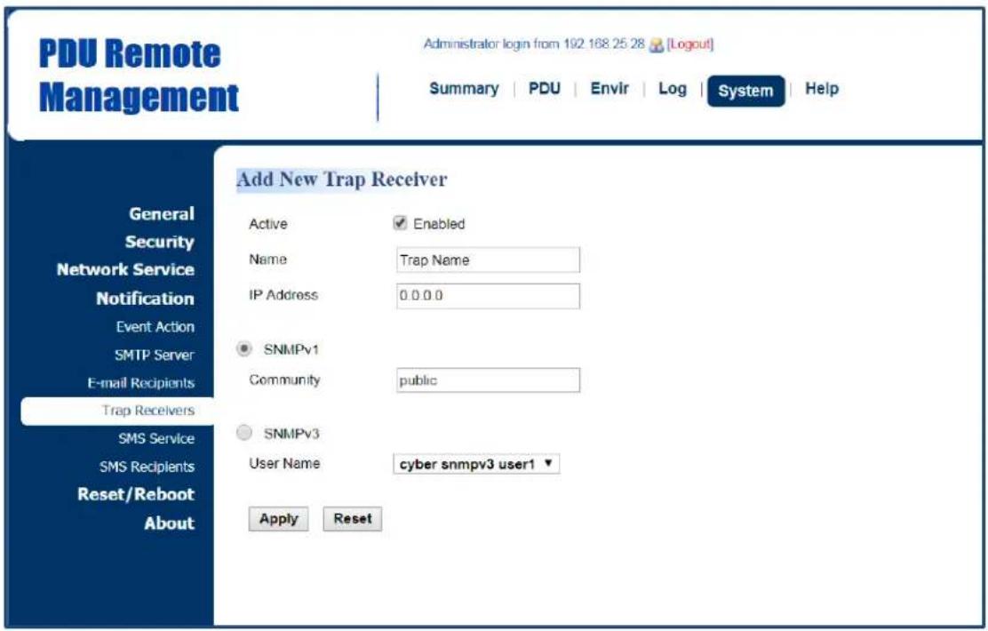
PDU Remote Management Administrator login from 192 168 25 28 [Logout] Summary | PDU | Envir | Log | System | Help Configure Trap Receiver General Security Network Service Notification Event Action SMTP Server E-mail Recipients Trap Receivers SMS Service SMS Recipients Reset/Reboot About Active Enabled Name Trap Name IP Address 0.0.0.0 SNMPv1 Community public SNMPv3 User Name cyber snmpv3 user1 ▼ Apply Reset DeleteAdd New Trap Receiver Page
text_image
PDU Remote Management Administrator login from 192 168 25 28 [Logout] Summary | PDU | Envir | Log | System | Help Add New Trap Receiver General Security Network Service Notification Event Action SMTP Server E-mail Recipients Trap Recivers SMS Service SMS Recipients Reset/Reboot About Active Enabled Name Trap Name IP Address 0.0.0.0 SNMPv1 Community public SNMPv3 User Name cyber snmpv3 user1 ▼ Apply Reset| Item | Definition |
| Name | The name of trap receiver. |
| IP Address | The IP address of the trap receiver. |
| SNMPv1 | If choosing the SNMPv1 option as the trap type for a trap receiver, select the corresponding community. See System Tab > Network Service > SNMPv1 Service. |
| SNMPv3 | If choosing the SNMPv3 option as the trap type for a trap receiver, select the corresponding user name. See System Tab > Network Service > SNMPv3 Service. |
3. SMS Notification
Short Message Service (SMS) is used by mobile communication systems to send a short message to a specific mobile phone number. Standardized communication protocols allow the exchange of short text messages between mobile devices.
The system provides four methods for users to choose how they want to send a message. See System > Notification > SMS Service.
System > Notification > SMS Service

text_image
PDU Remote Management Administrator login from 192.168.25.28 [Logout] Summary | PDU | Envir | Log | System | Help SMS Service Service Provider: Clickatell ▼ User Name tedmosby Password himym HTTP API ID 2014331 Apply Reset General Security Network Service Notification Event Action SMTP Server E-mail Recipients Trap Recivers SMS Service SMS Recipients Reset/Reboot AboutClickatell method:
Clickatell is one of the supported SMS service providers. Go to the Clickatell website to sign up and get an API ID.
| Item | Definition |
| User name | The account username created on Clickatell website. |
| User password | The user password created on Clickatell website. |
| HTTP API ID | The API ID acquired on Clickatell website. |
System > Notification > SMS Service
text_image
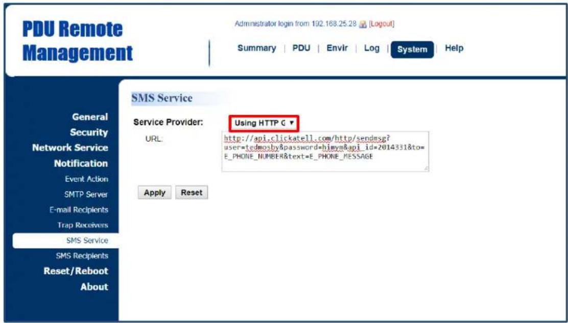
PDU Remote Management Administrator login from 192.168.25.28 [Logout] Summary | PDU | Envir | Log | System | Help General Security Network Service Notification Event Action SMTP Server E-mail Recipients Trap Receivers SMS Service SMS Recipients Reset/Reboot About SMS Service Service Provider: URL: Using HTTP G http://api.clickatell.com/http/sendmsg? user=tedmosby&password=himym&api_id=2014331&to= E_PHONE_NUMBER&text=E_PHONE_MESSAGE Apply ResetUsing HTTP GET:
Use the example where Clickatell is the SMS provider.
The basic form of URL using the HTTP GET method is:
http://api.clickatell.com/http/sendmsg?user=tedmosby&password=himym&api_id=2014331&to=E_PHONE_NUMBER&text=E_PHONE_MESSAGE
| Query String in the URL | Definition |
| user=tedmosby | Replace “tedmosby” with the user name created at the Clickatell website. |
| password=himym | Replace “himym” with the password created at the Clickatell website. |
| api_id=2014331 | Replace “2014331” with the API ID acquired at the Clickatell website. |
| to=E_PHONE_NUMBER | Do not replace this information. It refers to the receiver phone number entered in System Tab > Notification > SMS Recipients. |
| text=E_MESSAGE | Do not replace this information. It refers to the event action sent by the SMS service provider. For configurations, see System Tab > Notification > Event Action. |
System > Notification > SMS Service
text_image
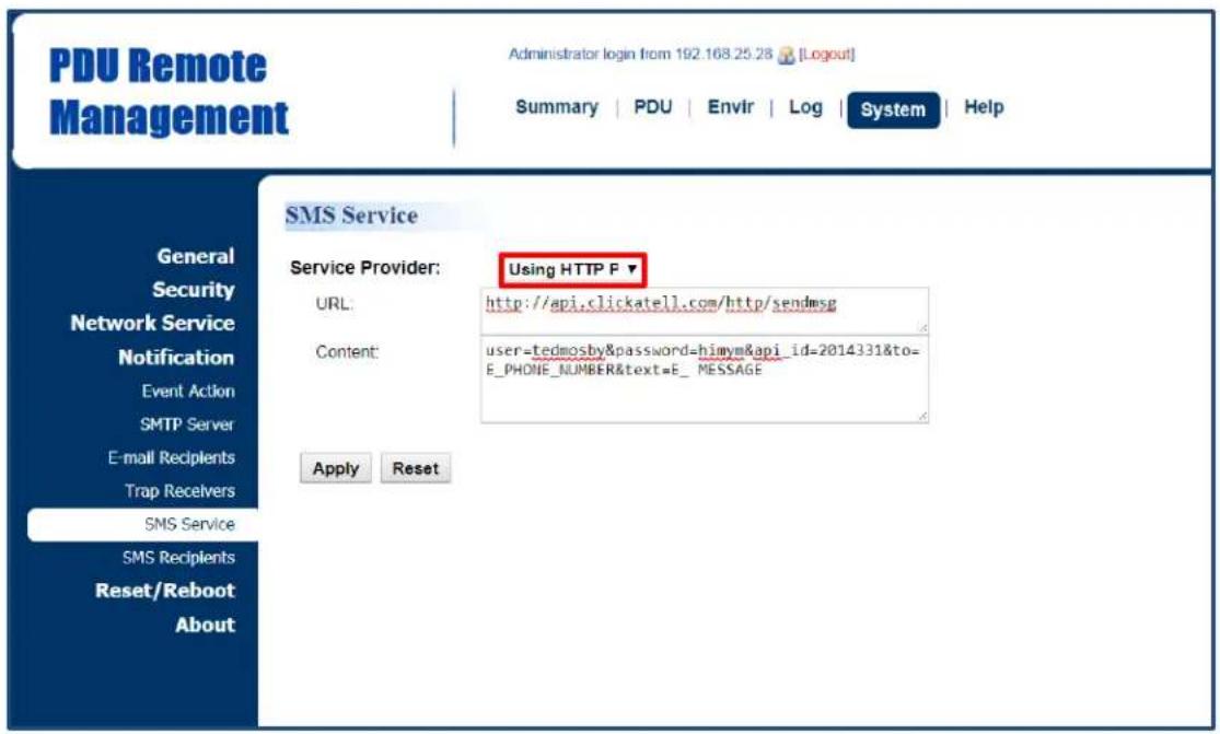
PDU Remote Management Administrator login from 192.168.25.28 [Logout] Summary | PDU | Envir | Log | System | Help SMS Service Service Provider: Using HTTP F ▼ URL: http://api.clickatell.com/http/sendmsg Content: user=tedmosby&password=himym&api_id=2014331&to= E_PHONE_NUMBER&text=E_MESSAGE Apply ResetUsing HTTP POST:
Use the example where Clickatell is the SMS provider.
The basic form of URL is: http://api.clickatell.com/http/sendmsg
The basic form of body is:
user=tedmosby&password=himym&api_id=2014331&to=E_PHONE_NUMBER&text=E_MESSAGE
| Query String in Body | Definition |
| user=tedmosby | Replace “tedmosby” with the user name created at the Clickatell website. |
| password=himym | Replace “himym” with the password created at the Clickatell website. |
| api_id=2014331 | Replace “2014331” with the API ID acquired at the Clickatell website. |
| to=E_PHONE_NUMBER | Do not replace this information. It refers to the receiver phone number entered in System Tab > Notification > SMS Recipients. |
| text=E_MESSAGE | Do not replace this information. It refers to the event action sent by SMS service provider. For configurations, see System Tab > Notification > Event Action. |
System > Notification > SMS Service
text_image
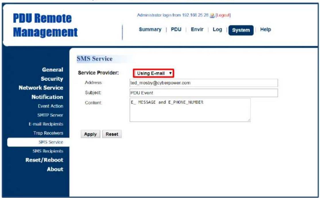
PDU Remote Management Administrator login from 192.168 25 28 [Logout] Summary | PDU | Envir | Log | System | Help SMS Service Service Provider: Using E-mail ▼ Address: ted_mosby@cyberpower.com Subject: PDU Event Content: E_ MESSAGE and E_PHONE_NUMBER Apply Reset General Security Network Service Notification Event Action SMTP Server E-mail Recipients Trap Recivers SMS Service SMS Recipients Reset/Reboot AboutUsing Mail:
Users set the SMTP server in System Tab > Notification > SMTP Server first, and then enter the following information.
| Item | Definition |
| Address | Enter the e-mail of the recipient. |
| Subject | The Subject field shown in the e-mail message, entered by user. |
| Content | |
| E_MESSAGE | Do not replace this information. It refers to the event action sent by SMS service provider. For configurations, see System Tab > Notification > Event Action. |
| E_PHONE_NUMBER | Do not replace this information. It refers to the receiver phone number entered in System Tab > Notification > SMS Recipients. |
Users can set up to 10 mobile phone numbers as SMS recipients who will receive a short message notification when a specific event occurs. See System Tab > Notification > SMS Recipients.
System Tab > Notification > SMS Recipients

text_image
PDU Remote Management Administrator login from 192.168.25.28 [Logud] Summary | PDU | Envir | Log | System | Help CyberPower SMS Recipients General Security Network Service Notification Event Action SMTP Server E-mail Recipients Trap Recovers SMS Service SMS Recipients Reset/Reboot About Status Recipient Name Mobile Number Send test Enabled Ted 0910000111 TEST New Recipient| Item | Definition |
| Recipient Name | Click the name of the recipient to open the Configure SMS Receiver Page. Users can modify or delete an existing receiver. |
| TEST | Click this button to check whether the test message is correctly sent. |
| New Recipient | Click this button to open the Add New SMS Receiver Page. Users can add a new recipient. |
Configure SMS Receiver Page

text_image
PDU Remote Management Administrator login from 192.168.25.28 [Logout] Summary | PDU | Envir | Log | System | Help Configure SMS Recipient Active ✓ Enabled Recipient Name Ted Mobile Number 0910000111 Apply Reset Delete General Security Network Service Notification Event Action SMTP Server E-mail Recipients Trap Receivers SMS Service SMS Recipients Reset/Reboot AboutAdd New SMS Receiver Page
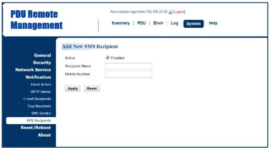
text_image
PDU Remote Management Administrator login from 192.168.25.28 [Logout] Summary | PDU | Envir | Log | System | Help Add New SMS Recipient Active Enabled Recipient Name Mobile Number Apply Reset General Security Network Service Notification Event Action SMTP Server E-mail Recipients Trap Recivers SMS Service SMS Recipients Reset/Reboot AboutOutlet Management
The following provides the outlet configurations to meet different application scenarios.
Remote Outlet On/Off/Reboot
Users can turn on, turn off, or reboot individual outlet. See PDU/ATS Tab > Outlet Action > Control. (For Switched Metered by Outlet Series and Switched Series only.)
PDU/ATS Tab > Outlet Action > Control

text_image
PDU Remote Management Administrator login from 192 168.25 26 [Logout] Summary | PDU | Envir | Log | System | Help Control Host Status Manager Outlet Action Control Schedule Daisy Chain Wake on Lan EnergyWise PowerPanel® List Control Action Turn On Delay Yes Outlet Selection All Status # Name ON 1 Outlet1 ON 2 Outlet2 ON 3 Outlet3 ON 4 Outlet4 ON 5 Outlet5 ON 6 Outlet6 ON 7 Outlet7 ON 8 Outlet8 Next > Reset| Item | Definition |
| HOST/GUEST# | Select the role of PDU/ATS (HOST or GUEST#) if PDU/ATSs are daisy chained. Up to 3 GUEST PDU/ATSs can connect to 1 HOST PDU/ATS. |
| Control Action | |
| Turn On | Selected outlets will be immediately turned on. |
| Turn On + Delay | Selected outlets will be turned on according to each outlet's Power On Delay in PDU/ATS Tab > Manager > Outlet. |
| Turn Off | Selected outlets will be immediately turned off. |
| Turn Off + Delay | Selected outlets will be turned off according to each outlet's Power Off Delay in PDU/ATS Tab > Manager > Outlet.This action could signal a computer to shut down, if PowerPoint® Business Remote software is installed on it. |
| Reboot | Selected outlets will be immediately turned off and then be turned on again according to each outlet's Reboot Duration in PDU/ATS Tab > Manager > Outlet. |
| Reboot + Delay | Selected outlets will be turned off according to each outlet's Power Off Delay. They will be synchronized with the longest Power Off Delay and the longest Reboot Duration of the selected outlets. Then they will be turned on according to each outlet's Power On Delay in PDU/ATS Tab > Manager > Outlet. |
| Cancel Pending Command | Any pending commands of the selected outlet(s) will be cancelled.Any outlet in a pending command state will be notated with an asterisk (*). |
| Outlet Selection | Outlets selected for action. |
Scheduled Outlet On/Off/Reboot
Outlet(s) can be set to automatically turn on, turn off, or reboot at scheduled times. See PDU/ATS Tab > Outlet Action > Schedule. (For Switched Metered by Outlet Series and Switched Series only.)
PDU/ATS Tab > Outlet Action > Schedule

text_image
PDU Remote Management Administrator login from 192.168.25.28 [Logout] Summary PDU Envir Log System Help Schedule Host Scheduled Action Status Name Action Action Time Frequency Outlet Add New Action Schedule Frequency Once Daily Weekly Next >Select the role of PDU/ATS (HOST or GUEST#) first if PDU/ATSs are daisy chained. Up to 3 GUEST PDU/ATS s can connect to 1 HOST PDU/ATS. Select the Once, Daily or Weekly option, and then click the Next button to enter the Add New Action Schedule Page.
| Item | Definition |
| Frequency | |
| Once | Scheduled action takes place once at the configured date and time. |
| Daily | Scheduled action takes place daily at the configured time. |
| Weekly | Scheduled action takes place once a week for the configured day and time. |
Add New Action Schedule Page

text_image
PDU Remote Management Administrator login from 192 168 25 28 [Logout] Summary | PDU | Envlr | Log | System | Help Add New Action Schedule - Once Status Manager Outlet Action Control Schedule Daisy Chain Wake on Lan EnergyWise PowerPanel® List Enable ✓ Name Schedule Name Control Action Turn On ▼ Delay □ Yes Action Time 7 ▼ / 26 ▼ at 11 ▼ : 17 ▼ Outlet Selection □ AllName
□ 1 Outlet1 □ 2 Outlet2 □ 3 Outlet3 □ 4 Outlet4 □ 5 Outlet5 □ 6 Outlet6 □ 7 Outlet7 □ 8 Outlet8 Apply ResetUp to 10 scheduled settings are allowed.
| Item | Definition |
| Enable | Check this box to activate the scheduled action function. |
| Name | The name entered by the user to identify the specific scheduled event. |
| Control Action | The action will be performed when the scheduled event takes place. For reboot action, selected outlets will be immediately turned off and then be turned on again according to outlet's Reboot Duration in PDU/ATS Tab > Manager > Outlet. The duration is within 5 to 60 seconds. |
| Delay | Click this box to activate outlet delay function. For configurations, see PDU/ATS Tab > Manager > Outlet |
| Action Time | The time at which the scheduled event takes place. |
| Outlet Selection | Outlets selected for the scheduled event. |
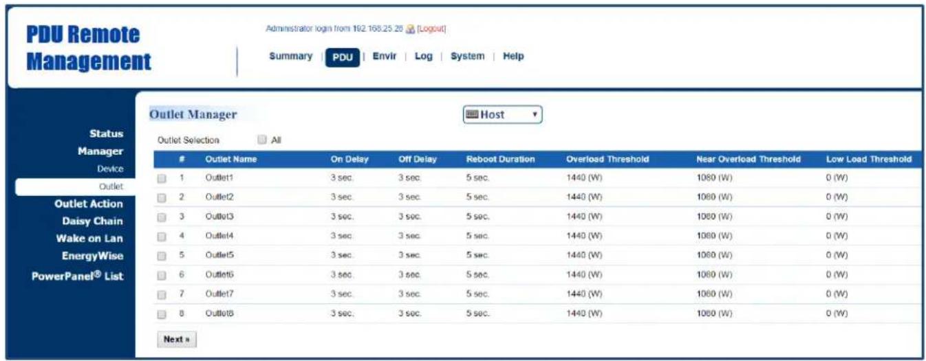
Sequencing Power On/Off/ Load Configuration
Enable users to turn on, turn off, or reboot the outlets in sequence. When powering on the connected devices, the sequential power-on method is recommended to avoid high inrush current. (For Switched Metered by Outlet Series and Switched Series only.)
The configurable load threshold can be set to prevent an overload condition. Users can set the value for amount of current placed on the selected outlet(s) that will signal an Overload threshold, Near Overload threshold, and Low Overload threshold warning. (For Switched Metered by Outlet Series and Metered by Outlet Series only.)
See PDU/ATS Tab > Manager > Outlet.
PDU/ATS Tab > Manager > Outlet
text_image
PDU Remote Management Administrator login from 192.168.25.26 [Logout] Summary PDU Envir Log System Help Status Manager Device Outlet Outlet Action Daisy Chain Wake on Lan EnergyWise PowerPanel® List Outlet Manager Host Outlet Selection AllOutlet Name On Delay Off Delay Reboot Duration Overload Threshold Near Overload Threshold Low Load Threshold
1 Outlet1 3 sec. 3 sec. 5 sec. 1440 (W) 1080 (W) 0 (W) 2 Outlet2 3 sec. 3 sec. 5 sec. 1440 (W) 1080 (W) 0 (W) 3 Outlet3 3 sec. 3 sec. 5 sec. 1440 (W) 1080 (W) 0 (W) 4 Outlet4 3 sec. 3 sec. 5 sec. 1440 (W) 1080 (W) 0 (W) 5 Outlet5 3 sec. 3 sec. 5 sec. 1440 (W) 1080 (W) 0 (W) 6 Outlet6 3 sec. 3 sec. 5 sec. 1440 (W) 1080 (W) 0 (W) 7 Outlet7 3 sec. 3 sec. 5 sec. 1440 (W) 1080 (W) 0 (W) 8 Outlet8 3 sec. 3 sec. 5 sec. 1440 (W) 1080 (W) 0 (W) Next >Select the role of PDU/ATS (HOST or GUEST#) first if PDU/ATSs are daisy chained. Up to 3 GUEST PDU/ATSs can connect to 1 HOST PDU/ATS. Click the box to select one outlet or multiple outlets for power sequencing and then click Next to open the Outlet Configuration Page for configuration.
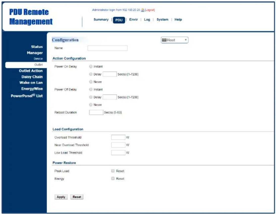
Outlet Configuration Page
text_image
PDU Remote Management Administrator login from 192.198.25.28 [Logout] Summary | PDU | Envir | Log | System | Help Status Manager Device Outlet Outlet Action Daisy Chain Wake on Lan EnergyWise PowerPanel® List Configuration Name Action Configuration Power On Delay Instant Delay Sec(s) [1-7200] Never Power Off Delay Instant Delay Sec(s) [1-7200] Never Reboot Duration Sec(s) [5-60] Load Configuration Overload Threshold W Near Overload Threshold W Low Load Threshold W Power Restore Peak Load Reset Energy Reset Apply Reset Host| Item | Definition |
| Name | The name entered by the user to identify the selected outlet or multiple outlet configuration. |
| Action Configuration* | |
| Power On/Off Delay | *Instant: Turn on/off the outlet immediately.*Delay: Delay time before turning on/off the outlet. Valid values are within the range of 1 to 7,200 seconds.*Never: Never turn on/off the outlet. |
| Reboot Duration | The length of time the outlet will remain off during a Reboot action. Valid values are within the range of 5 to 60 seconds. |
| Load Configuration** | |
| Overload Threshold | Set the value for individual outlet that will signal an overload warning in Watts. Must be higher than Near Overload Threshold. |
| Near Overload Threshold | Set the value for individual outlet that will signal a near overload warning in Watts. Must be between Overload Threshold and Low Load Threshold. |
| Low Overload Threshold | Set the value for individual outlet that will signal a low overload warning in Watts. Must be lower than Near Overload Threshold. |
| Power Restore | |
| Peak Load | Restore the peak load of each outlet to zero. |
| Energy | Restore the energy of each outlet to zero. |
* For Switched Metered by Outlet Series and Switch Series only.
** For Switched Metered by Outlet and Metered by Outlet Series only.
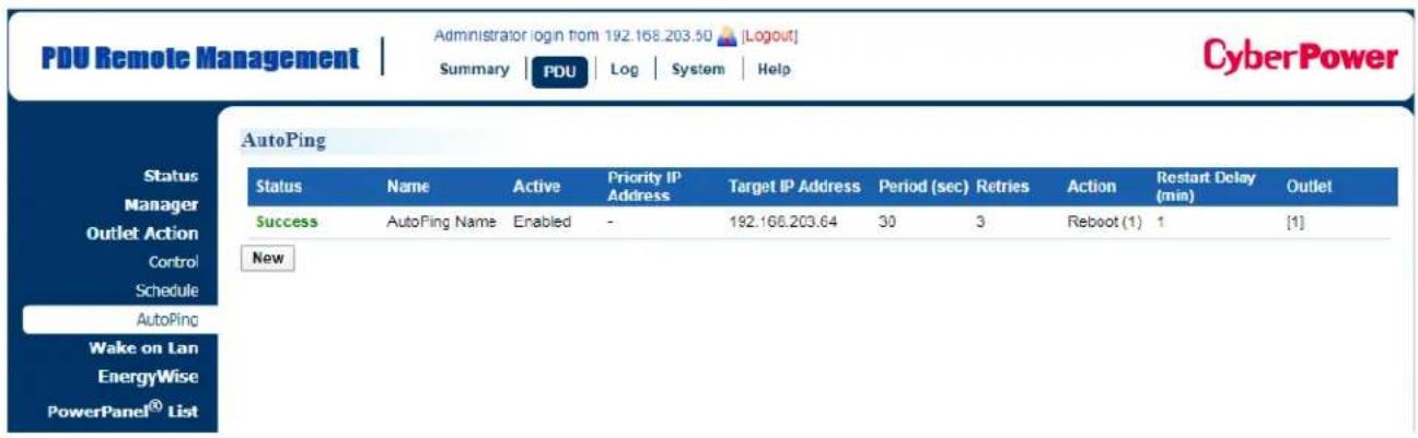
AutoPing
The AutoPing feature allows the PDU/ATS to detect if a target device becomes unresponsive to IP pings and automatically reboot the device. If the device gets back to normal operation after reboot, network connection could be restored at the same time.
To utilize the function, See PDU/ATS Tab > Outlet Action > AutoPing. (For Switched Metered by Outlet Series and Switched Series only.)

text_image
PDU Remote Management Administrator login from 192.160.203.50 [Logout] Summary | PDU | Log | System | Help CyberPower AutoPing Status Name Active Priority IP Address Target IP Address Period (sec) Retries Action Restart Delay Outlet Manager Outlet Action Control Schedule AutoPing Wake on Lan EnergyWise PowerPanel® List NewAutoPing configuration is shown as below. For example, the AutoPing function is enabled on Outlet 1 with 192.168.203.64 as "Target IP address". The PDU/ATS sends IP pings to the target device every 30 seconds. Outlet1 reboots once only if ping tests fail 3 times in a row, which takes 90 seconds for the PDU/ATS to detect the failure and trigger the action. After Outlet1 reboots, no pings are sent to the target device until 1 minute of "Restart Delay" is reached.

text_image
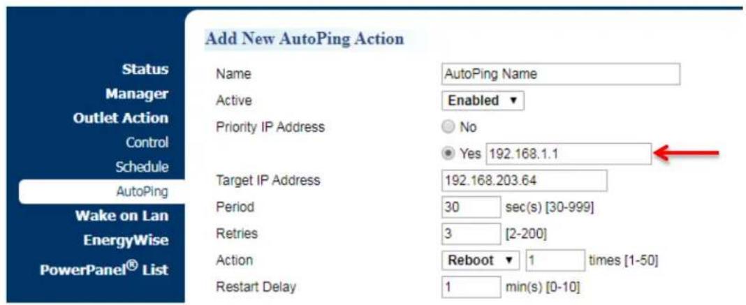
PDU Remote Management Administrator login from 192.168.203.50 [Logout] Summary | PDU | Log | System | Help CyberPower Add New AutoPing Action Status Manager Outlet Action Control Schedule AutoPing Wake on Lan EnergyWise PowerPanel® List Name AutoPing Name Active Enabled ▼ Priority IP Address No Yes Target IP Address 192.168.203.64 Period 30 sec(s) [30-999] Retries 3 [2-200] Action Reboot ▼ 1 times [1-50] Restart Delay 1 min(s) [0-10] Outlet Selection All Bank 1 Bank 2 Bank 1 Bank 2Name # Name
✓ 1 Outlet1 9 Outlet9 □ 2 Outlet2 10 Outlet10 □ 3 Outlet3 11 Outlet11 □ 4 Outlet4 12 Outlet12 □ 5 Outlet5 13 Outlet13 □ 6 Outlet6 14 Outlet14 □ 7 Outlet7 15 Outlet15 □ 8 Outlet3 16 Outlet16 Apply ResetUp to 10 AutoPing settings are allowed.
| Item | Definition |
| Active | Enable/Disable the AutoPing function. |
| Priority IP Address | When “Yes” is selected, sets the IP address of the priority to utilize the function. Pings will only be sent to the target device when receiving a successful ping response from the priority. For example, the target device is connected to a router, which is set to be the priority. The PDU/ATS sends IP pings to the target device only if the router is responsive to IP pings. In this way, the PDU/ATS can verify network connection by sending IP pings to the priority first and determine if target IP ping test is performed accordingly. |
| Target IP Address | The IP address of the target device. |
| Period | The time interval between successive pings to the target device, in second. |
| Retries | The number of failed ping tests that must be consecutively detected before the action is triggered. |
| Action | The action on specific outlet if the PDU/ATS continuously receives no response from the target device. When “Reboot” is selected, sets the maximum number of times to be triggered. |
| Restart Delay | Length of time after an action is triggered before beginning to restart ping tests. This allows a proper time for the device to get back to normal operation. During this time interval, no pings are sent to the target device. |
After confirming the AutoPing configuration and pressing "Apply" button, find your preferred configuration and AutoPing status on AutoPing Webpage.
text_image
PDU Remote Management Administrator login from 192.168.203.50 [Logout] Summary | PDU | Log | System | Help CyberPower AutoPing Status Name Active Priority IP Address Target IP Address Period (sec) Retries Action Restart Delay Outlet Success AutoPing Name Enabled - 192.168.203.64 30 3 Reboot (1) 1 [1] New Wake on Lan EnergyWise PowerPanel® ListBesides, set the IP address of the priority when "Yes" is selected. For example, the target device is connected to a router, which is set to be the priority. The PDU/ATS sends IP pings to the target device only if the router is responsive to IP pings. In this way, the PDU/ATS can verify network connection by sending IP pings to the priority first and determine if target IP ping test is performed accordingly.
text_image
Add New AutoPing Action Status Manager Outlet Action Control Schedule AutoPing Wake on Lan EnergyWise PowerPanel® List Name Active Priority IP Address Target IP Address Period Retries Action Restart Delay AutoPing Name Enabled No Yes 192.168.1.1 192.168.203.64 30 sec(s) [30-999] 3 [2-200] Reboot 1 times [1-50] 1 min(s) [0-10]Wake on LAN (WoL)
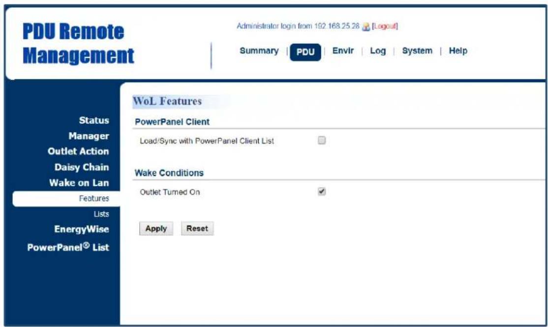
When turning on an outlet, a Wake on LAN packet can be sent to the connected computer to awaken it. It is necessary for the computer to support this function and is configured as "Enabled" in its BIOS settings. See PDU/ATS Tab > Wake on LAN > Features and PDU/ATS Tab > Wake on LAN > Lists. (For Switched Metered by Outlet Series and Switched Series only.)
PDU/ATS Tab > Wake on LAN > Features
text_image
PDU Remote Management Administrator login from 192.168.25.28 [Logout] Summary | PDU | Envlr | Log | System | Help Status Manager Outlet Action Daisy Chain Wake on Lan Features Lists EnergyWise PowerPanel® List WoL Features PowerPanel Client Load/Sync with PowerPoint Client List Wake Conditions Outlet Turned On Apply Reset| Item | Definition |
| PowerPanel Remote | Load/Sync with PowerPanel List. To achieve synchronization, make sure the PDU/ATS has established communication with PowerPanel® Business Remote software. See System Tab > Security > Authentication. |
| Wake Conditions | Enable or disable the Wake on LAN function. |
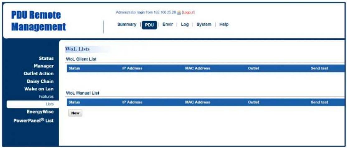
PDU/ATS Tab > Wake on LAN > Lists
text_image
PDU Remote Management Administrator login from 192 168.25.26 [Logout] Summary | PDU | Envir | Log | System | Help WoL Lists Wol. Client List Status IP Address MAC Address Outlet Send test Wol. Manual List Status IP Address MAC Address Outlet Send test New Status IP Address MAC Address Outlet Send test EnergyWise PowerPanel® List| Item | Definition |
| WoL Remote List | If the PowerPanel Remote option in PDU/ATS Tab > Wake on LAN > Features is selected, the PowerPanel® List will be automatically added to the WoL Remote list. |
| WoL Manual List | Click New to enter the Add Wake on LAN Receiver Page. Users can manually add WoL receivers. |
Add Wake on LAN Receiver Window

text_image
PDU Remote Management Administrator login from 192.168.25.28 [Logout] Summary PDU Envir Log System Help Add Wake on Lan Receiver Status Manager Outlet Action Daisy Chain Wake on Lan Features Lists EnergyWise PowerPanel® List Active Enabled IP Address 0.0.0.0 OutletName
1 Outlet1 2 Outlet2 3 Outlet3 4 Outlet4 5 Outlet5 6 Outlet6 7 Outlet7 8 Outlet8 Apply Reset| Item | Definition |
| Active | Enable/Disable the Wake on LAN function. |
| IP Address | The IP address of the computer. This IP must be within the same subnet as the PDU/ATS. Up to 50 IP addresses are supported. |
| Outlet | Select the outlet that provides power to the computer. |
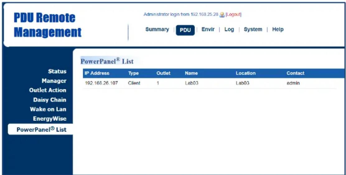
Graceful Computer Shutdown
After the connected computer is installed with PowerPanel Business Remote or Management and establishes communication with the PDU/ATS, its IP address will be automatically displayed in the PowerPanel® List shown below. This computer can perform a safe shutdown before the outlet powering the computer turns off, thus avoiding data loss. To achieve communication between the computer and PDU/ATS, see System > General > Security.
Up to 50 computers having PPBE Remote or Management installed can be listed. A Remote or Management computer will be removed when it has been disconnected from the PDU/ATS for an hour. See PDU/ATS Tab > PowerPanel® List. (For Switched Metered by Outlet Series and Switched Series only.)
PDU/ATS Tab > PowerPanel® List
text_image
PDU Remote Management Administrator login from 192.168.25.28 [Logout] Summary | PDU | Envir | Log | System | Help PowerPanel® List Status Manager Outlet Action Daisy Chain Wake on Lan EnergyWise PowerPanel® List IP Address Type Outlet Name Location Contact 192.168.26.107 Client 1 Lab03 Lab03 adminClick the IP address of a client to access configuration settings.
Cisco EnergyWise
Users can manage and control all Cisco EnergyWise entities and configure settings. See PDU/ATS Tab > EnergyWise > Configuration and PDU/ATS Tab > EnergyWise > Children List.
PDU/ATS Tab > EnergyWise > Configuration

text_image
PDU Remote Management Administrator login from 192.166.25.28 [Logout] Summary PDU Envir Log System Help EnergyWise Configuration Status Manager Outlet Action Daisy Chain Wake on Lan EnergyWise Configuration Children List PowerPanel® List Version 1.2.0 EnergyWise Enable Service port 43440 Domain Name Off-State Cache Secure Mode Shared Secret Apply Reset| Item | Definition |
| Version | The version of EnergyWise supported. |
| EnergyWise | Enable/Disable EnergyWise support. |
| Service Port | The port number is used to communicate with EnergyWise.This number must be the same as that of a Cisco switch that the PDU/ATS connects to. |
| Domain Name | The EnergyWise domain name.This must be the same as that of a Cisco switch that the PDU/ATS connects to. |
| Off-State Cache | Enable/Disable endpoint to cache EnergyWise list in the Cisco switch after the PDU/ATS has rebooted. |
| Secure Mode | Enable EnergyWise use of a shared secret. |
| Shared Secret | The secret for the EnergyWise domain. |
PDU/ATS Tab > EnergyWise > Children List

text_image
PDU Remote Management Administrator login from 102.168.25.28 [Logout] Summary PDU Envir Log System Help EnergyWise Children List Status Manager Outlet Action Daisy Chain Wake on Lan EnergyWise Configuration Children List PowerPanel® List ParentName Role Keywords importance
1 PDU_Base base,role endpoint,child,base 1 ChildrenName Role Keywords importance
1 Outlet1 outlet,role endpoint,child,outlet 1 2 Outlet2 outlet,role endpoint,child,outlet 1 3 Outlet3 outlet,role endpoint,child,outlet 1 4 Outlet4 outlet,role endpoint,child,outlet 1 5 Outlet5 outlet,role endpoint,child,outlet 1 6 Outlet6 outlet,role endpoint,child,outlet 1 7 Outlet7 outlet,role endpoint,child,outlet 1 8 Outlet8 outlet,role endpoint,child,outlet 1 9 Bank1 bank,role endpoint,child,bank 1Click the Name field in parent and/or children list to enter the EnergyWise Parent Configuration Page and EnergyWise Child Configuration Page.
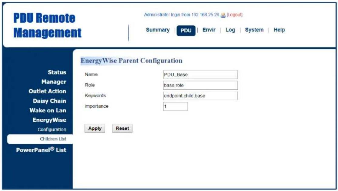
EnergyWise Parent Configuration Page
text_image
PDU Remote Management Administrator login from 192 168.25.28 [Logout] Summary | PDU | Envir | Log | System | Help EnergyWise Parent Configuration Status Manager Outlet Action Daisy Chain Wake on Lan EnergyWise Configuration Children List PowerPanel® List Name PDU_Base Role base,role Keywords endpoint,child,base Importance 1 Apply ResetEnergyWise Child Configuration Page
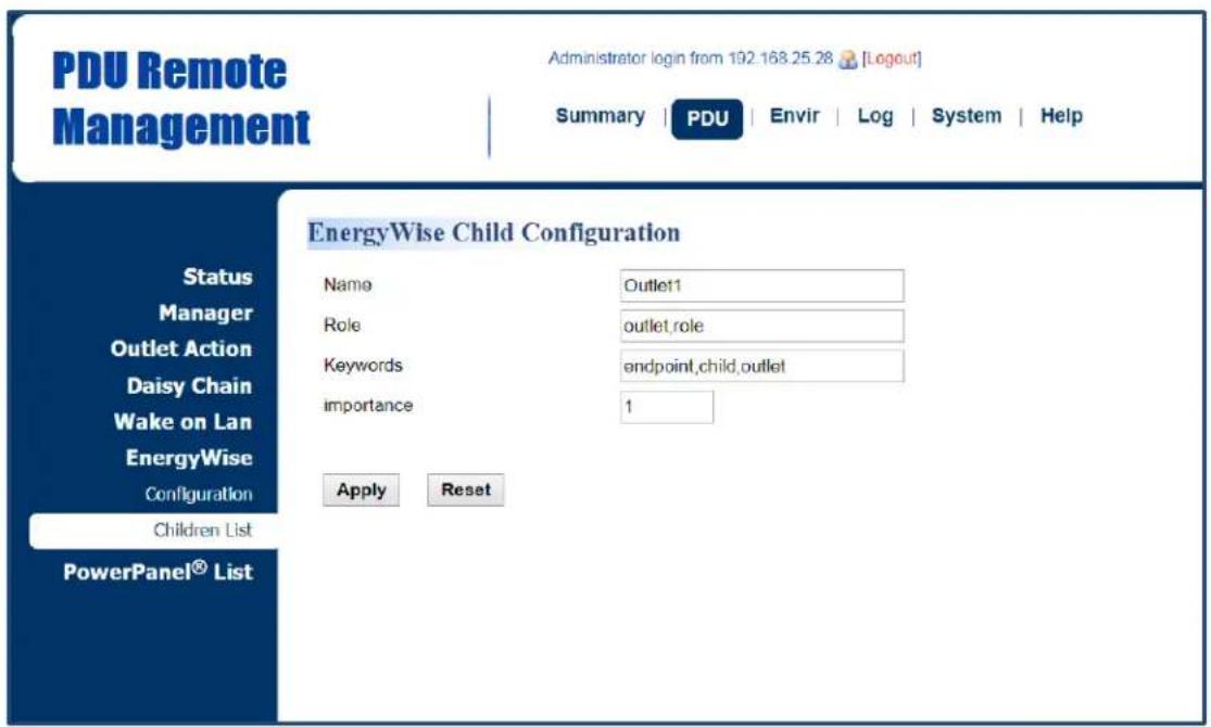
text_image
PDU Remote Management Administrator login from 192.168.25.28 [Logout] Summary | PDU | Envir | Log | System | Help EnergyWise Child Configuration Status Manager Outlet Action Daisy Chain Wake on Lan EnergyWise Configuration Children List PowerPanel® List Name Outlet11 Role outlet,role Keywords endpoint,child,outlet Importance 1 Apply Reset| Item | Definition |
| Name | The name entered by the user to identify an EnergyWise entity.The maximum length is 31 characters. |
| Role | This parameter is a string entered by the user to describe the function ofthe entity. Maximum length is 31 characters. |
| Keywords | This parameter is a string entered by the user to describe the entity.Maximum length is 31 characters. |
| Importance | This parameter, entered by the user, shows the value of an entity's importance and must be between 1 and 100. |
Security
The following provides account configurations to protect against unauthorized entry.
Login Authentication
There are five options for login authentication. Only one user can log in to the web interface at a time.
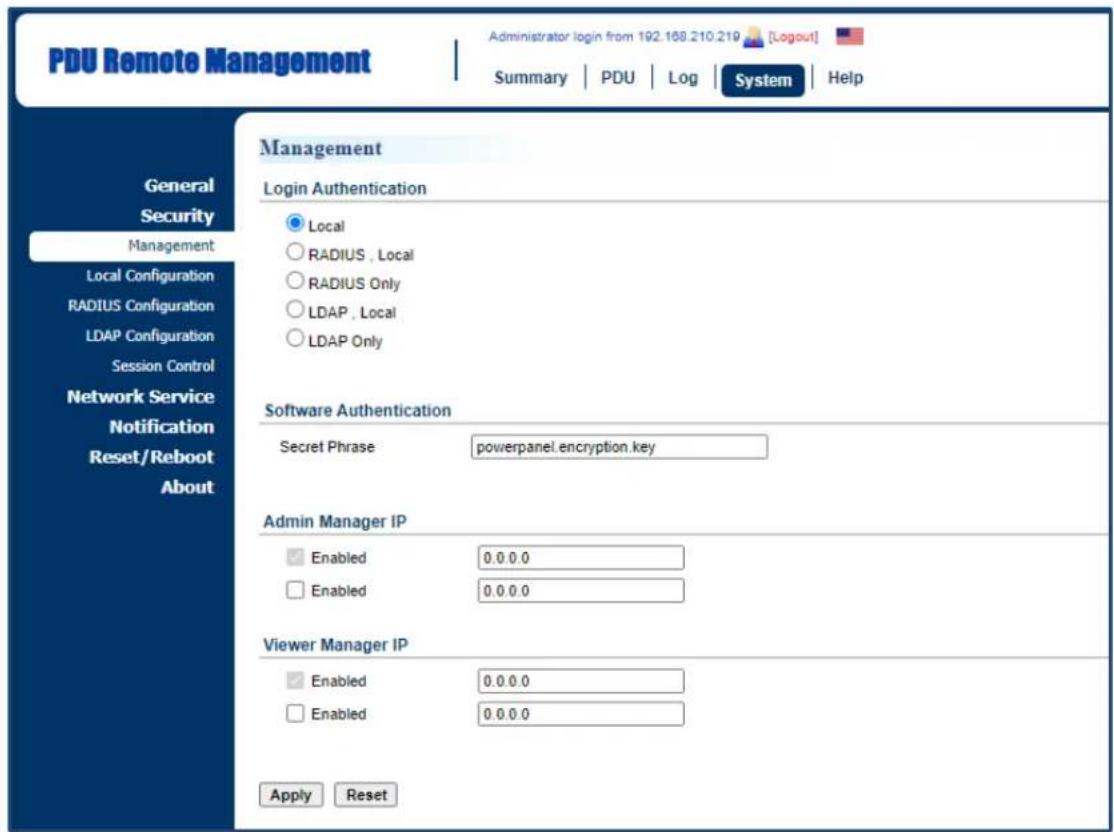
System Tab > Security > Management
text_image
PDU Remote Management Administrator login from 192.168.210.219 [Logout] Summary | PDU | Log | System | Help General Security Management Local Configuration RADIUS Configuration LDAP Configuration Session Control Network Service Notification Reset/Reboot About Management Login Authentication Local RADIUS, Local RADIUS Only LDAP, Local LDAP Only Software Authentication Secret Phrase powerpanel.encryption.key Admin Manager IP Enabled 0.0.0.0 Enabled 0.0.0.0 Viewer Manager IP Enabled 0.0.0.0 Enabled 0.0.0.0 Apply Reset| Item | Definition |
| Login Authentication | |
| Local | Log in with user name and password configured in Local Account. See System Tab > Security > Local Configuration. |
| RADIUS, Local | Log in with user name and password to authenticate with RADIUS server first. If the RADIUS server fails to respond, then the user name and password configured in Local Configuration can be used. See System Tab > Security > RADIUS Configuration. |
| RADIUS Only | Log in with user name and password to authenticate with RADIUS server only. See System Tab > Security > RADIUS Configuration. |
| LDAP, Local | Log in with user name and password to authenticate with LDAP server first. If the LDAP server fails to respond, then the user name and password configured in Local Configuration can be used. See System Tab > Security > LDAP configuration. |
| LDAP Only | Log in with user name and password to authenticate with LDAP server only. See System Tab > Security > LDAP configuration. |
| Software Authentication | |
| Secret Phrase | The authentication phrase is used to communicate with PowerPoint® Business software. This phrase should be the same Secret Phrase as the field on PowerPoint® Business software interface. |
| Manager IP | |
| Admin Manager IP (optional) | Set the Admin IP which is allowed to access. If you want access from any IP address, you can set one of them as 0.0.0.0 or 255.255.255.255.Note: You can also set a range of IP addresses to access, for example, 192.168.16.1/24. |
| Viewer Manager IP (optional) | Set the Viewer IP which is allowed to access. If you want access from any IP address, you can set one of them as 0.0.0.0 or 255.255.255.255.Note: You can also set a range of IP addresses to access, for example, 192.168.16.1/24. |
1. Using Local Configuration for Authentication
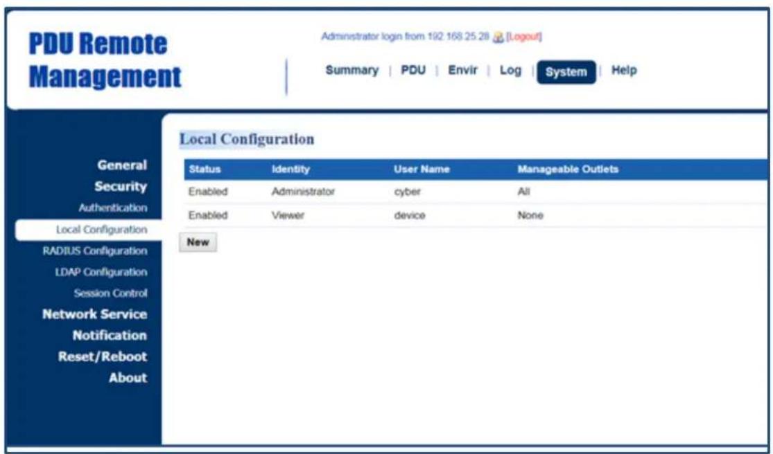
System Tab > Security > Local Configuration
text_image
PDU Remote Management Administrator login from 192 168 25 28 [Logout] Summary | PDU | Envir | Log | System | Help General Security Authentication Local Configuration RADIUS Configuration LDAP Configuration Session Control Network Service Notification Reset/Reboot About Local Configuration Status Identity User Name Manageable Outlets Enabled Administrator cyber All Enabled Viewer device None NewThere are two types of account: administrator and viewer. Click User Name field to enter Administrator Page or Viewer Page. Users can also click NEW to enter Add Outlet User Page to create an outlet account.
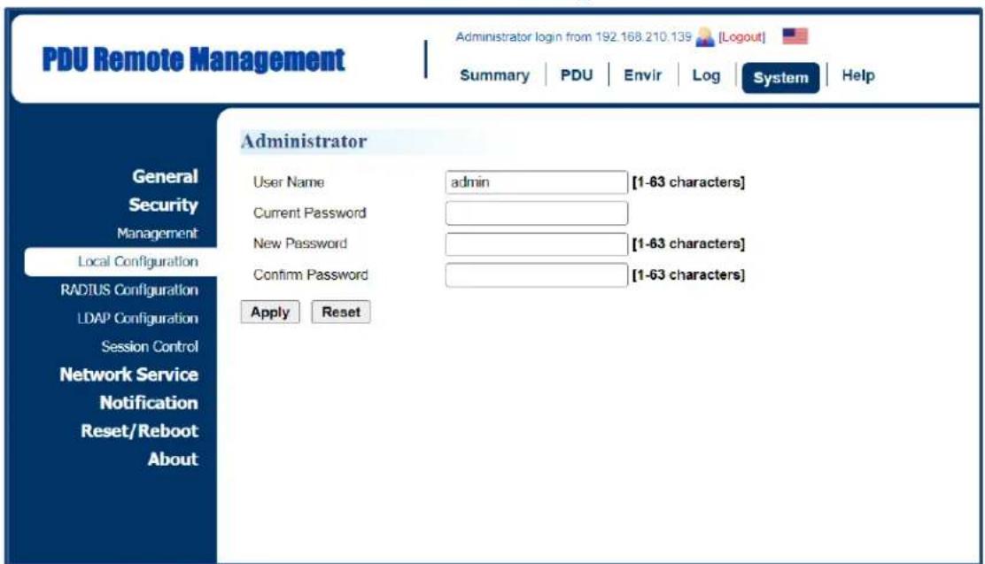
Administrator Page
text_image
PDU Remote Management Administrator login from 192.168.210.139 [Logout] Summary | PDU | Envir | Log | System | Help General Security Management Local Configuration RADIUS Configuration LDAP Configuration Session Control Network Service Notification Reset/Reboot About Administrator User Name admin [1-63 characters] Current Password New Password [1-63 characters] Confirm Password [1-63 characters] Apply ResetViewer Page
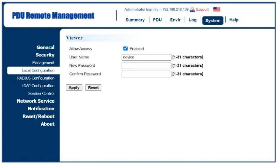
text_image
PDU Remote Management Administrator login from 192.168.210.139 [Logout] Summary | PDU | Envir | Log | System | Help General Security Management Local Configuration RADIUS Configuration LDAP Configuration Session Control Network Service Notification Reset/Reboot About Viewer Allow Access ✓ Enabled User Name device [1-31 characters] New Password [1-31 characters] Confirm Password [1-31 characters] Apply Reset| Item | Definition |
| Administrator | The administrator can access all functions, including Enable/Disable the Viewer account. For login configuration, users can only create one administrator account. |
| User Name | Enter the new user name. |
| Current Password | Enter the current password for authentication. |
| New Password | Enter the new password. |
| Confirm Password | Enter the new password again to confirm it. |
| Viewer | The viewer can view the settings but cannot control or change any settings. |
| Allow Access | Check this box to enable view account. |
Add Outlet User Page*
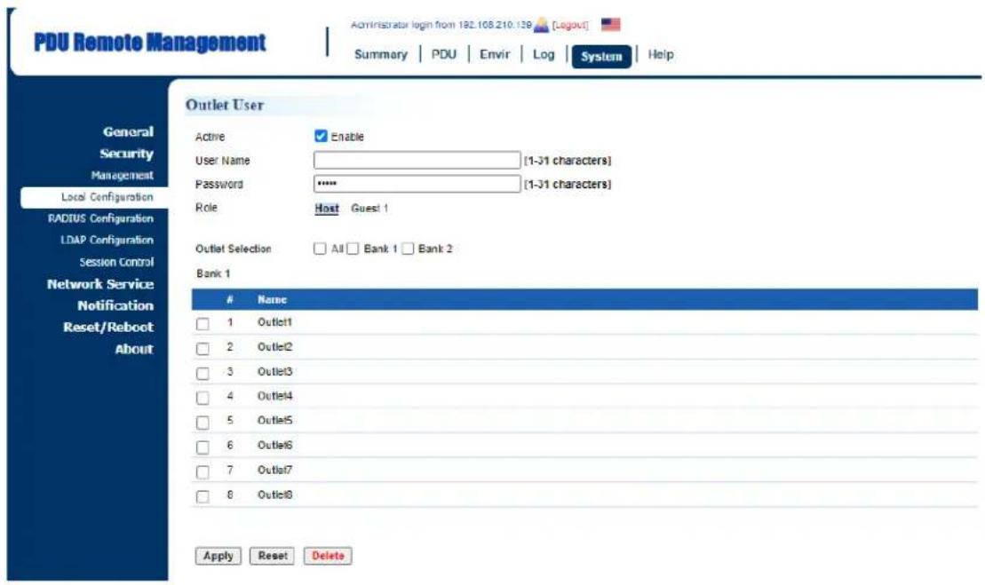
text_image
PDU Remote Management Administrator login from 192.108.210.139 [Logout] Summary | PDU | Envir | Log | System | Help General Security Management Local Configuration RADIUS Configuration LDAP Configuration Session Control Network Service Notification Reset/Reboot About Outlet User Active Enable User Name [1-31 characters] Password ***** [1-31 characters] Role Host Guest 1 Outlet Selection All Bank 1 Bank 2 Bank 1Name
1 Outlet1 2 Outlet2 3 Outlet3 4 Outlet4 5 Outlet5 6 Outlet6 7 Outlet7 8 Outlet8 Apply Reset DeleteUsers can create an outlet account that is allowed to control assigned outlet(s).
| Item | Definition |
| Active | Enable or disable the user account. |
| User Name | Set a name for the user account. |
| Password | Set the user password. |
| Role | Select the role of the PDU/ATS (HOST or GUEST#) if PDU/ATSs are daisy chained. Up to 3 GUEST PDU/ATSs can connect to 1 HOST PDU/ATS. |
| Outlets Selection | Outlets that the user can control. |
2. Using RADIUS Configuration for Authentication
System Tab > Security > RADIUS Configuration
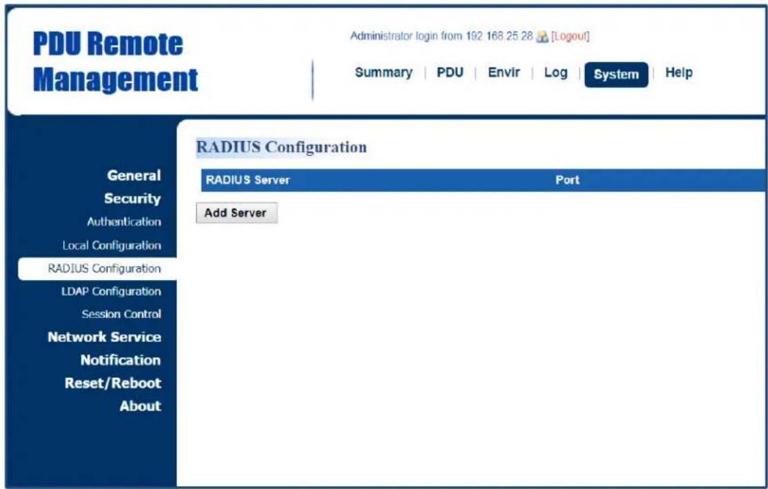
text_image
PDU Remote Management Administrator login from 192 168.25 28 [Logout] Summary | PDU | Envir | Log | System | Help RADIUS Configuration RADIUS Server Port Add Server General Security Authentication Local Configuration RADIUS Configuration LDAP Configuration Session Control Network Service Notification Reset/Reboot AboutClick Add Server to enter Radius Server Configuration Page to create a server.
Radius Server Configuration Page
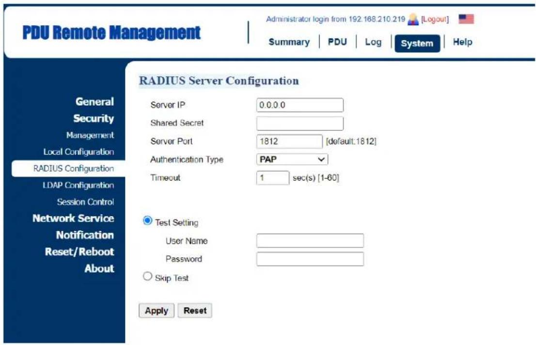
text_image
PDU Remote Management Administrator login from 192.168.210.219 [Logout] Summary PDU Log System Help RADIUS Server Configuration General Security Management Local Configuration RADIUS Configuration LDAP Configuration Session Control Network Service Notification Reset/Reboot About Server IP 0.0.0.0 Shared Secret Server Port 1812 [default:1812] Authentication Type PAP Timeout 1 sec(s) [1-60] Test Setting User Name Password Skip Test Apply Reset| Item | Definition |
| Server IP | The IP address of RADIUS server. |
| Shared Secret | The shared secret of RADIUS server. |
| Server Port | The UDP port used by the RADIUS server. |
| Authentication Type | The authentication protocol type for RADIUS Server.Password authentication protocol (PAP)Challenge-Handshake Authentication Protocol (CHAP) |
| Timeout | The time of waiting to login Radius server. |
| Test Setting | Use user name and password to authenticate with RADIUS server, and save information of RADIUS server if authentication succeeds. |
| Skip Test | Save information of the RADIUS server without test. |
3. Using LDAP Configuration for Authentication
System Tab > Security > LDAP configuration

text_image
PDU Remote Management Administrator login from 192.168.25.28 [Logout] Summary | PDU | Envir | Log | System | Help General Security Authentication Local Configuration RADIUS Configuration LDAP Configuration Session Control Network Service Notification Reset/Reboot About LDAP Configuration LDAP Server Type LDAP SSL Add ServerClick Add Server to enter LDAP Server Configuration Page to create a server.
LDAP Server Configuration Page
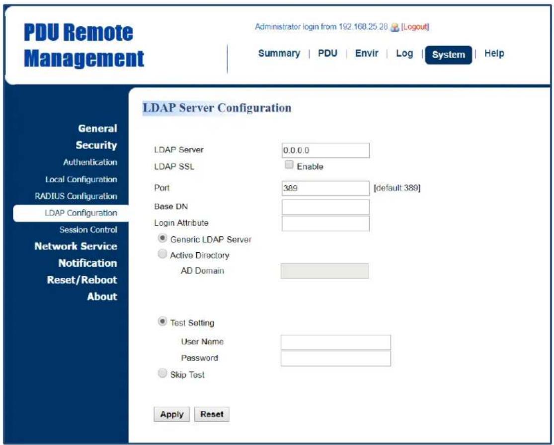
text_image
PDU Remote Management Administrator login from 192 168.25.28 [Logout] Summary | PDU | Envir | Log | System | Help General Security Authentication Local Configuration RADIUS Configuration LDAP Configuration Session Control Network Service Notification Reset/Reboot About LDAP Server Configuration LDAP Server 0.0.0.0 LDAP SSL Enable Port 389 [default 389] Base DN Login Attribute ● Generic LDAP Server ● Active Directory AD Domain ● Test Setting User Name Password ○ Skip Test Apply Reset| Item | Definition |
| LDAP Server | The IP address of LDAP server. |
| LDAP SSL | To communicate with LDAP server by LDAPS. |
| Port | The TCP port used by the LDAP(S) server. |
| Base DN | The base DN of LDAP server. |
| Login Attribute | The login attribute of LDAP user entry. (ex: cn or uid) |
| Generic LDAP Server | The type of LDAP server. |
| Active Directory | Select LDAP server type as Windows AD |
| AD Domain | The AD Domain of the Active Directory server. |
| Test Setting | Use user name and password to authenticate with LDAP server, and save information of LDAP server if authentication succeeds. |
| Skip Test | Save information of the RADIUS server without test. |
Timeout Setting
Configure the idle login sessions. See System > Security > Session Control.
System > Security > Session Control
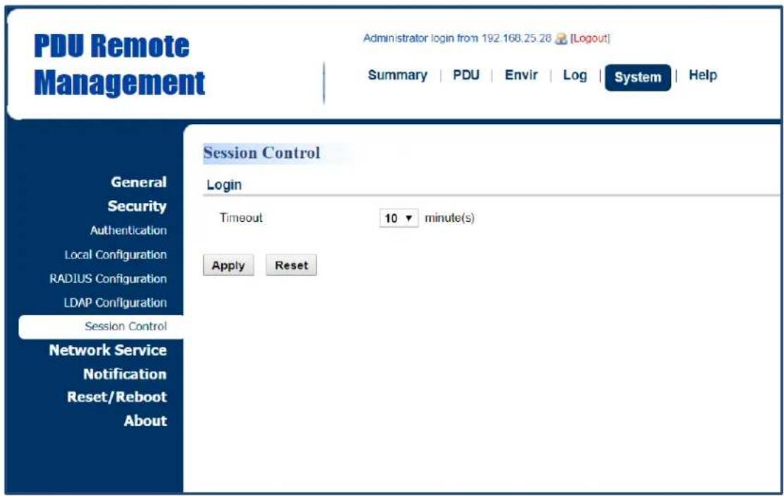
text_image
PDU Remote Management Administrator login from 192.168.25.28 [Logout] Summary | PDU | Envir | Log | System | Help Session Control Login Timeout 10 minute(s) Apply Reset General Security Authentication Local Configuration RADIUS Configuration LDAP Configuration Session Control Network Service Notification Reset/Reboot About| Item | Definition |
| Login Session | |
| Timeout | The time in minutes that the system waits before automatically logging off. |
Network Service
The following provides the network configurations.
TCP/IPv4 Setting
Display the current TCP/IPv4 settings and allow users to select the option to obtain TCP/IP settings by DHCP. See System > Network Service > TCP/IPv4.
System > Network Service > TCP/IPv4

text_image
PDU Remote Management Administrator login from 192.168.210.219 [Logout] Summary | PDU | Log | System | Help TCP/IPv4 Current Configuration IP Address 192.168.202.186 Subnet Mask 255.255.255.0 Gateway 192.168.202.254 DNS Server 192.168.20.125 Active Host Name Active Domain Name DHCP Enable DHCP Manual IP Address 192.168.202.186 Subnet Mask 255.255.255.0 Gateway 192.168.202.254 DNS Server 192.168.20.125 Host Name Host Name PDU81001 Synchronization with Identification Name Apply Reset| Item | Definition |
| Current Configuration | Display the current TCP/IP settings: IP Address, Subnet Mask, Gateway, and DNS server. |
| DHCP | *Enable DHCP: Select this option to get IP address, Subnet Mask, and Gateway from DHCP.*Obtain DNS Address from DHCP: Select this option to get DNS by DHCP if DHCP is enabled. |
| Manual | Unselect Enable DHCP first.Enter the TCP/IP settings manually and click Apply. |
| Host Name | Configure a host name.*Synchronization with Identification Name - Allow the identification name to be synchronized with the host name so both fields automatically contain the same value.Note: When enabling this feature, the identification name can only contain numbers (0-9), letters (a-z, A-Z), hyphen and decimal point. Besides, the identification name should not start with hyphen or decimal point. |
TCP/IPv6 Setting
Display the current TCP/IPv6 settings and allow users to assign the IPv6 address either by router control or manually. See System > Network Service > TCP/IPv6.
System > Network Service > TCP/IPv6
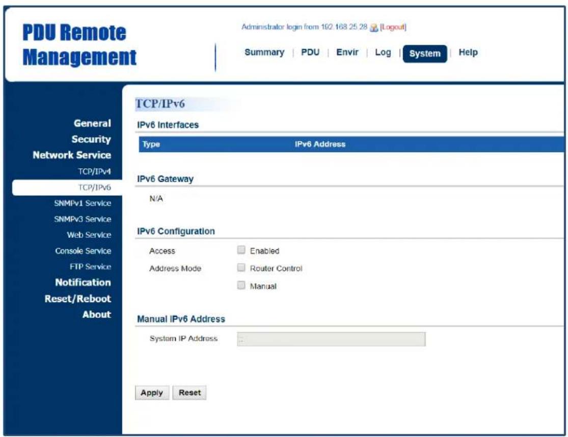
text_image
PDU Remote Management Administrator login from 102.168.25.28 [Logout] Summary | PDU | Envir | Log | System | Help General Security Network Service TCP/IPv4 TCP/IPv6 SNMPv1 Service SNMPv3 Service Web Service Console Service FTP Service Notification Reset/Reboot About TCP/IPv6 IPv6 Interfaces Type IPv6 Address IPv6 Gateway N/A IPv6 Configuration Access Enabled Address Mode Router Control Manual Manual IPv6 Address System IP Address Apply Reset| Item | Definition |
| IPv6 Interface | Displays the current IPv6 address. |
| IPv6 Gateway | Displays the current IPv6 gateway. |
| IPv6 Configuration | |
| Allow Access | Enable/Disable IPv6 service. |
| Address Mode:Router Control | The IPv6 address is assigned through the method (Stateless Address Auto configuration, Stateless DHCPv6, or Stateful DHCPv6) determined by the router's configuration. |
| Address Mode:Manual | The IPv6 address is assigned manually. |
| Manual IPv6Address | Enter the IPv6 address manually and click Apply when the Address Mode: Manual option is selected. |
SNMPv1 Service Setting
Allow users to perform SNMPv1 configurations. See System Tab > Network Service > SNMPv1 Service.
System Tab > Network Service > SNMPv1 Service
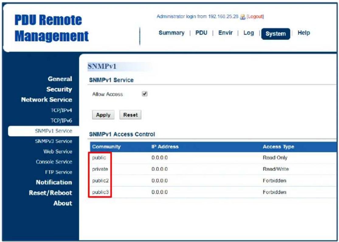
text_image
PDU Remote Management Administrator login from 192.168.25.28 [Logout] Summary | PDU | Envir | Log | System | Help SNMPv1 SNMPv1 Service Allow Access ✓ Apply Reset SNMPv1 Access Control Community IP Address Access Type public 0.0.0.0 Read Only private 0.0.0.0 Read/Write public2 0.0.0.0 Forbidden public3 0.0.0.0 Forbidden| Item | Definition |
| SNMPv1 Service | |
| Allow Access | Enable or disable the SNMPv1 service. |
Click the SNMP Trap Community field to enter the SNMPv1 Page. Users can configure the SNMPv1 settings.
SNMPv1 Page
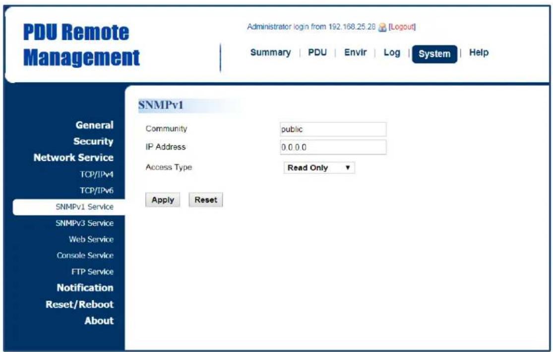
text_image
PDU Remote Management Administrator login from 192.168.25.28 [Logout] Summary | PDU | Envir | Log | System | Help SNMPv1 General Security Network Service TCP/IPv4 TCP/IPv6 SNMPv1 Service SNMPv3 Service Web Service Console Service FTP Service Notification Reset/Reboot About Community public IP Address 0.0.0.0 Access Type Read Only Apply Reset| Item | Definition |
| Community | The name used to access the SNMP community from a Network Management System (NMS). Its maximum length is 15 characters. |
| IP Address (IPv6 Support) | The IP address or IP address mask can be accessed by the NMS. A specific IP address allows access only by the NMS with the specified IP Address. The “255” is regarded as the subnet mask and the rules are as follows:*192.168.20.255: Access only by an NMS on the 192.168.20.0 segment.*192.255.255.255: Access only by an NMS on the 192.0.0.0 segment.*0.0.0.0 (the default setting) or 255.255.255.255: Access by any NMS on any segments. |
| Access Type | The allowable action for the NMS through the community and IP address.*Read Only: GET at any time but cannot SET.*Write/Read: GET at any time. SET at any time unless someone logs in to the Web interface.*Forbidden: No GET or SET. |
SNMPv3 Service Setting
Users can perform SNMPv3 configurations. Authentication type or privacy type are provided to strengthen security. See System Tab > Network Service > SNMPv3 Service.
System Tab > Network Service > SNMPv3 Service
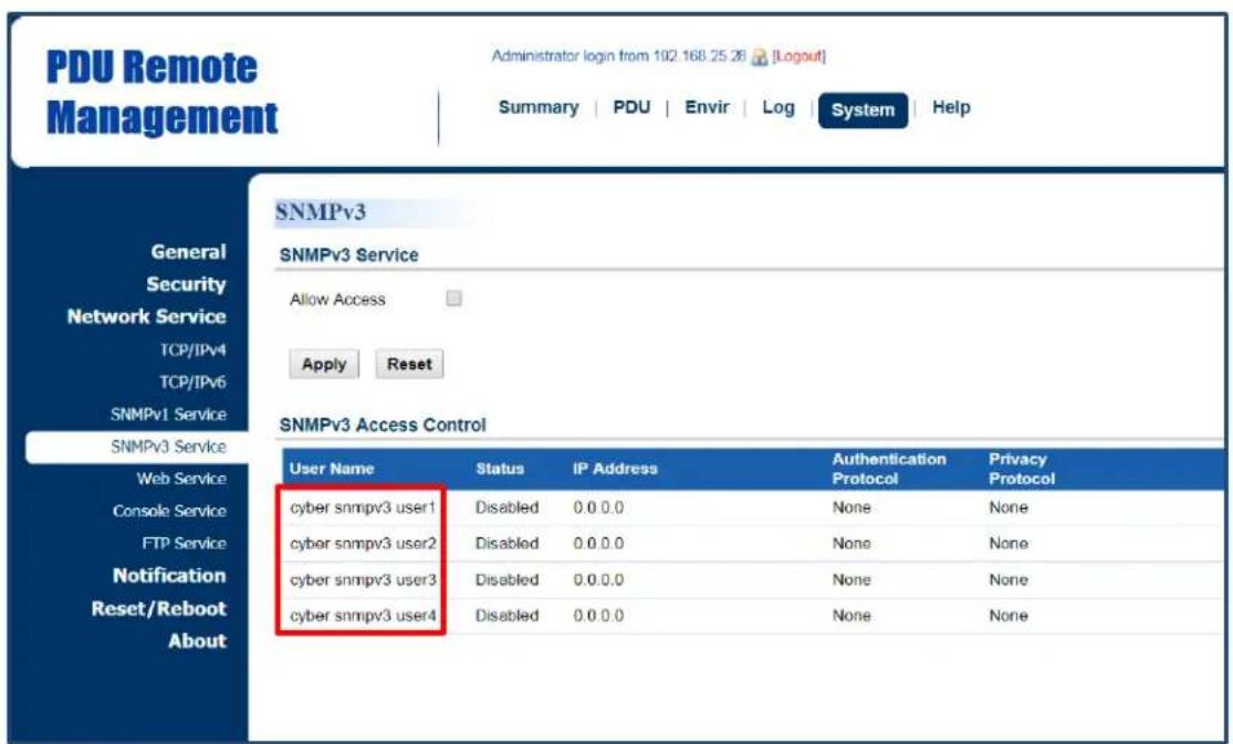
text_image
PDU Remote Management Administrator login from 102.168.25.26 [Logout] Summary | PDU | Envir | Log | System | Help SNMPv3 SNMPv3 Service Allow Access Apply Reset SNMPv3 Access Control User Name Status.IP Address Authentication Privacy Protocol Protocol cyber snmpv3 user1 Disabled 0.0 0.0 None None cyber snmpv3 user2 Disabled 0.0 0.0 None None cyber snmpv3 user3 Disabled 0.0 0.0 None None cyber snmpv3 user4 Disabled 0.0 0.0 None None| Item | Definition |
| SNMPv3 Service | |
| Allow Access | Enable or disable the SNMPv3 service. |
Click the User Name field to enter the SNMPv3 Page. Users can configure SNMPv3 settings.
SNMPv3 Page
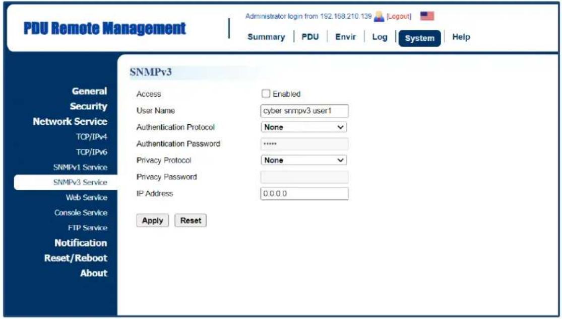
text_image
PDU Remote Management Administrator login from 192.168.210.139 [Logout] Summary | PDU | Envir | Log | System | Help SNMPv3 General Security Network Service TCP/IPv4 TCP/IPv6 SNMPv1 Service SNMPv3 Service Web Service Console Service FTP Service Notification Reset/Reboot About SNMPv3 Access Enabled User Name cyber snmpv3 user1 Authentication Protocol None Authentication Password ****** Privacy Protocol None Privacy Password IP Address 0.0.0.0 Apply Reset| Item | Definition |
| Access | Enable or disable the SNMPv3 service. |
| User Name | The name that identifies the SNMPv3 user. It must be 1 to 31 characters long. |
| Authentication Protocol | The hash type for authentication. |
| Authentication Password | The password used to generate the key for authentication. It must be 16 to 31 characters long. |
| Privacy Protocol | The type for encrypting and decrypting data.Note: The privacy protocol can not be selected if no authentication protocol is selected |
| Privacy Password | The password used to generate the key for encryption. It must be 16 to 31 characters long. |
| IP Address (IPv6 Support) | The IP address or IP address mask that can be accessed by the NMS. A specific IP address allows access only by the NMS with the specified IP Address. The “255” is regarded as the subnet mask and the rules are as follows:*192.168.20.255: Access only by an NMS on the 192.168.20.0 segment.*192.255.255.255: Access only by an NMS on the 192.0.0.0 segment.*0.0.0.0 (the default setting) or 255.255.255.255: Access by any NMS on any segments. |
Web Service
Select the Enable HTTP/HTTPS option to access the HTTP/HTTPS Service and configure HTTP/HTTPS port settings. See System Tab > Network Service > Web Service.
System Tab > Network Service > Web Service
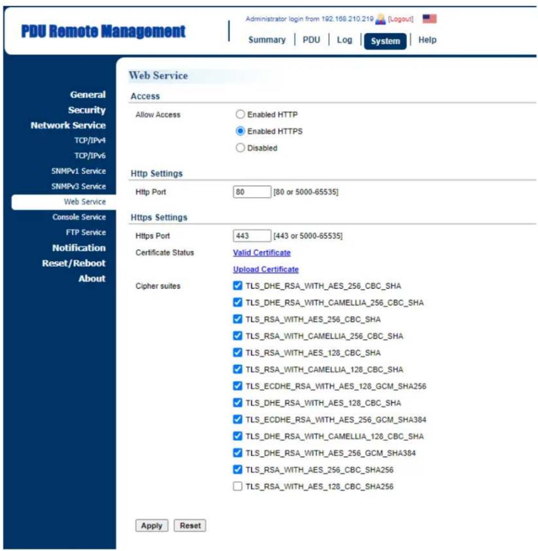
text_image
PDU Remote Management Administrator login from 192.168.210.219 [Logout] Summary | PDU | Log | System | Help General Security Network Service TCP/IPv4 TCP/IPv6 SNMPv1 Service SNMPv3 Service Web Service Console Service FTP Service Notification Reset/Reboot About Web Service Access Allow Access Enabled HTTP Enabled HTTPS Disabled Http Settings Http Port 80 [80 or 5000-65535] Https Settings Https Port 443 [443 or 5000-65535] Certificate Status Valid Certificate Upload Certificate Cipher suites ✓ TLS_DHE_RSA_WITH_AES_256_CBC_SHA ✓ TLS_DHE_RSA_WITH_CAMELLIA_256_CBC_SHA ✓ TLS_RSA_WITH_AES_256_CBC_SHA ✓ TLS_RSA_WITH_CAMELLIA_256_CBC_SHA ✓ TLS_RSA_WITH_AES_128_CBC_SHA ✓ TLS_RSA_WITH_CAMELLIA_128_CBC_SHA ✓ TLS_ECDHE_RSA_WITH_AES_128_GCM_SHA256 ✓ TLS_DHE_RSA_WITH_AES_128_CBC_SHA ✓ TLS_ECDHE_RSA_WITH_AES_256_GCM_SHA384 ✓ TLS_DHE_RSA_WITH_CAMELLIA_128_CBC_SHA ✓ TLS_DHE_RSA_WITH_AES_256_GCM_SHA384 ✓ TLS_RSA_WITH_AES_256_CBC_SHA256 □ TLS_RSA_WITH_AES_128_CBC_SHA256 Apply Reset| Item | Definition |
| Access | |
| Allow Access | Enable or disable HTTP/HTTPS service. HTTPS supports the following encryption algorithms:● AES (256/128 bits)● Camellia (256/128 bits) |
| Http Settings | |
| HTTP Port | The TCP/IP port of the Hypertext Transfer Protocol (HTTP); 80 is the default value.Users can also change the port setting to any unused port from 5000 to 65535 to enhance security. |
| Https Settings | |
| Https Port | The TCP/IP port of the Hypertext Transfer Protocol Secure (HTTPS); 443 is the default value.Users can also change the port setting to any unused port from 5000 to 65535 to enhance security. |
| Certificate Status | *Valid Certificate: Display the detailed certificate information.*Upload Certificate: Upload a certificate and replace the current one. The certificate must be uploaded in standard PEM (Privacy Enhanced Mail) format. |
| Cipher suites | Set the Cipher suite to either Enable or Disable. |
Click the Valid Certificate link, and the Installed Certificate Page will appear.
Installed Certificate Page
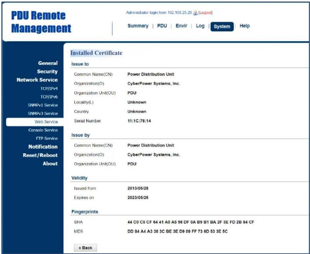
text_image
PDU Remote Management Administrator login from 192.168.25.28 [Logout] Summary | PDU | Envir | Log | System | Help General Security Network Service TCP/IPv4 TCP/IPv6 SNMPv1 Service SNMPv3 Service Web Service Console Service FTP Service Notification Reset/Reboot About Installed Certificate Issue to Common Name(CN) Power Distribution Unit Organization(O) CyberPower Systems, Inc. Organization Unit(OU) PDU Locality(L) Unknown Country Unknown Serial Number 11:1C:76:14 Issue by Common Name(CN) Power Distribution Unit Organization(O) CyberPower Systems, Inc. Organization Unit(OU) PDU Validity Issued from 2013/05/28 Expires on 2023/05/26 Fingerprints SHA 44 C0 C5 CF 64 41 A0 A5 98 DF 0A B9 B1 BA 2F 3E FD 2B 84 CF MD5 DD 84 A4 A3 38 3C BE 3E D9 09 FF 73 6D 53 3E 5C « BackClick the Upload Certificate link, and the Change Certificate Page will appear.
Change Certificate Page

text_image
PDU Remote Management Administrator login from 192.168.25.28 [Logout] Summary | PDU | Envir | Log | System | Help General Security Network Service TCP/IPv4 TCP/IPv6 SNMPv1 Service SNMPv3 Service Web Service Console Service FTP Service Notification Reset/Reboot About Upload and Replace Upload Certificate Select File Submit « BackConsole Service
Select the Enable options to allow access using Telnet/SSH service and configure Telnet/SSH port settings. See System Tab > Network Service > Console Service.
System Tab > Network Service > Console Service

text_image
PDU Remote Management Administrator login from 192 168 210 139 [Logout] Summary | PDU | Envir | Log | System | Help Console Access Allow Access Enable Telnet Enable SSH Disabled Telnet Settings Telnet Port 23 [23 or 5000-65535] SSH Settings SSH Port 22 [22 or 5000-65535] Hostkey Status Valid Upload Hostkey Export Hostkey Hostkey Fingerprint: D6 58 DD D3 A6 DF 01 29 50 02 B7 0C 76 03 91 29 Apply Reset General Security Network Service TCP/IPv4 TCP/IPv6 SNMPv1 Service SNMPv3 Service Web Service Console Service FTP Service Notification Reset/Reboot About| Item | Definition |
| Access | |
| Allow Access | Enable access using Telnet or SSH version 2, which transmits use names, passwords, and data in an encrypted format. |
| Telnet Settings | |
| Telnet Port | The TCP/IP port that Telnet uses to communicate; 23 is the default value. Users can change the port setting to any unused port from 5000 to 6553 to enhance security.Note: Telnet Client requires users to enter a space and the port number after the PDU/ATS IP address on the command line to access the control console. |
| SSH Settings | |
| SSH Port | The TCP/IP port that SSH uses to communicate; 22 is the default value.Users can change port setting to any unused port from 5000 to 65535 to enhance security. |
| Hostkey Status | Display the status of hostkey fingerprint to show whether it is valid or invalid.Click Upload Hostkey to upload or change hostkey.Click Export Hostkey to export a current hostkey. |
| Hostkey Fingerprint | The hostkey fingerprint uploaded by users will be displayed in this field. |
FTP Service
Allow users to enable/disable the FTP server service and configure the TCP/IP port of the FTP server. The FTP server is used for upgrading Firmware. See System Tab > Network Service > FTP Service.
System Tab > Network Service > FTP Service

text_image
PDU Remote Management Administrator login from 192.168.25.28 [Logout] Summary | PDU | Envlr | Log | System | Help FTP General Security Network Service TCP/IPv4 TCP/IPv6 SNMPv1 Service SNMPv3 Service Web Service Console Service FTP Service Notification Reset/Reboot About Allow Access ✓ Enabled Service port 21 [21 or 5000-65535] Apply Reset| Item | Definition |
| Allow Access | Enable FTP server access. |
| Access Port | The TCP/IP port of the FTP server; 21 is the default value. Users can change port setting to any unused port from 5000 to 65535 to enhance security. |
PDU/ATS Information
Display the system information of the PDU/ATS. See System > About.
System > About
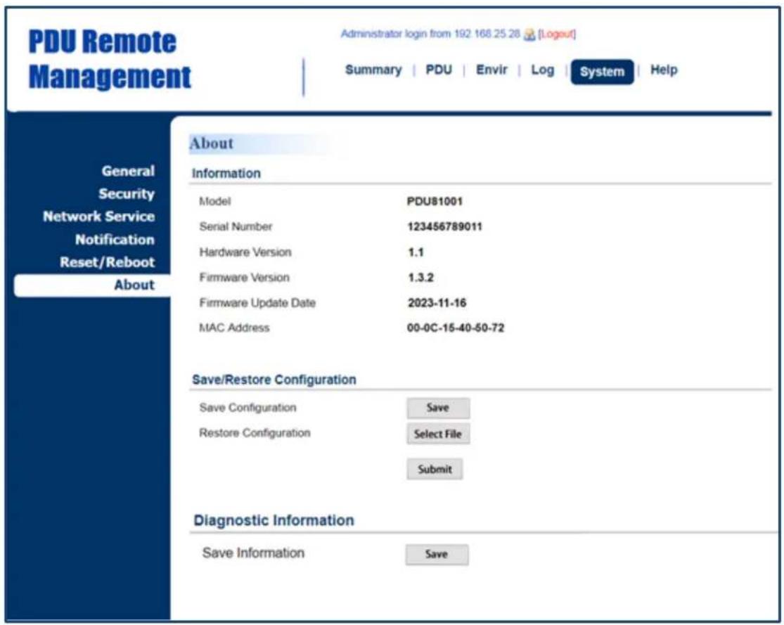
text_image
PDU Remote Management Administrator login from 192 168.25.28 [Logout] Summary | PDU | Envir | Log | System | Help About Information Model PDU81001 Serial Number 123456789011 Hardware Version 1.1 Firmware Version 1.3.2 Firmware Update Date 2023-11-16 MAC Address 00-0C-15-40-50-72 Save/Restore Configuration Save Configuration Save Restore Configuration Select File Submit Diagnostic Information Save Information Save| Item | Definition |
| Information | |
| Model Name | Model name of the PDU/ATS. |
| Serial Number | Serial Number of the PDU/ATS. |
| Hardware Version | The hardware version of the PDU/ATS. |
| Firmware Version | The current firmware version installed on the PDU/ATS. |
| Firmware Updated Date | The date the firmware was last updated. |
| MAC Address | MAC address of the PDU/ATS.Note: The MAC address is shown on the label on the back ofthe PDU/ATS and via the LCD screen on the PDU/ATS. |
| Save/Restore Settings | |
| Save Configuration | Click Save to save the PDU/ATS configuration file to local computer. The text file name will have a default format of YYYY_MM_DD_HHMM.txt. |
| Restore Configuration | To restore a configuration that has been saved earlier.Click Select File to import an existing configuration file and then click Submit. |
| Diagnostic Information | |
| Save Information | Click the "Save" button to save all diagnostic information to a file. The saved information includes Event Logs, Status Records and other device information. Its suggested to have this information saved when contacting CyberPower Technical Support for assistance. |
Command Line Interface
Introduction
How to log on
Users can log on to the command line interface through either console network access (Telnet or SSH) or local access (Serial port).
- Network access to the command line interface
When user logs in with the admin username and admin password through Telnet or SSH, there are two types of interfaces available. One is the command line interface (CLI) and the second is a menu interface. The default is CLI. If the user wants to change to the menu interface, type in the [menumode] command. To switch back to CLI, it is necessary to logout and login to the PDU/ATS.
- Local access to the command line interface
To log on via serial connection, the PC/server must be connected directly to the Universal port of the PDU/ATS using the included RJ45/DB9 Serial Port Connection Cable, and perform the following steps.
Step 1: Open Hyper Terminal software (eg. PuTTY, HyperTerminal, or Tera Term) on your PC and select a name and icon for the connection.
Step 2: Setup the COM port settings using the following values
Step 4: Enter the user name and password of the PDU/ATS at the Authentication menu.
Note: Serial connection can only access Command Line Mode and cannot support Menu Mode.
How to use telnet access command line interface
Step 1: Need to make sure the computer has access to the PDU/ATS installed network. At a command prompt, type telnet and the IP address for the PDU/ATS (for example, telnet 139.225.6.133, when the PDU/ATS uses the default Telnet port of 23), and press Enter.
Step 2: Enter the user name and password (by default, user name: cyber, password: cyber)
How to use SSH access command line interface
SSH is highly recommended for using to access the command line interface. SSH encrypts user
names, passwords, and transmitted data. To use SSH you must first configure SSH and install an SSH client program (eg. PuTTY, HyperTerminal, or Tera Term) on your computer.
Note: If using PuTTY to configure SSH access, please configure Line discipline of Terminal to "Force off", as shown in Figure 5.

text_image
PuTTY Configuration Category: Session Logging Terminal Keyboard Bell Features Window Appearance Behaviour Translation Selection Colours Connection Data Proxy Telnet Rlogin SSH Serial Options controlling the terminal emulation Set various terminal options Auto wrap mode initially on DEC Origin Mode initially on Implicit CR in every LF Implicit LF in every CR Use background colour to erase screen Enable blinking text Answerback to ^E: PuTTY Line discipline options Local echo: Auto Force on Force off Local line editing: Auto Force on Force off Remote-controlled printing Printer to send ANSI printer output to: None (printing disabled) About Open CancelFigure 5. The PuTTY Configuration window.
How to use the Command Line Interface
While using the command line interface, you can also do the following:
-
To close the connection to the command line interface → Type "exit" and press Enter
-
To switch mode as Menu Mode → Type "menumode" and press Enter
-
To view a list of available commands or arguments → Type “?” (Eg. date ?).
-
To view the command that was typed most recently in the session Press the UP/DOWN arrow key. (The session can remember up to ten previous commands.)
-
A command can support multiple options To define the date as March 21, 2015 (Eg. date yyyy 2015 mm 3 dd 21)
Command Response Codes
When the command or arguments is not recognized or is incorrect, the console interface will display [^] underneath the wrong command or argument. The following error message will be displayed:
| Command not found | PDU/ATS doesn’t know this command.Console interface display the list of available commands. |
| Parameter Error | The parameter type or format is not allowed. |
Console interface display the list of available value or format.
Command Lists
devsta
Description: Show device status of load and utility.
| Option | Argument | Description |
| show | Show information of system device load and utility status. | |
| guest | 1 | 2 | 3 | Select daisy chain index. |
Example 1:
To display device status
CyberPower > devsta show
devcfg
Description: Show and set device load threshold, reset power parameters in device level, set cold start status and delay.
| Option | Argument | Description |
| show | Show information of device configuration. | |
| guest | 1 | 2 | 3 | Select daisy chain index. |
| overload | Set device overload threshold value. | |
| nearover | Set device near overload threshold value. | |
| lowload | Set device low load threshold value. | |
| restriction | Set outlet restriction of device. | |
| pwrrest | peakload | energy | Reset the peak load or energy of device. |
| coldstasta | previous | allon | Set the cold start state of device. |
| coldstadly | -1 | 0 | 1 | 2 |...| 300 | Set the cold start delay of device. |
| idletime | 1 | 2 | 3 | 5 | 10 | never | Set idle time of device. |
Example 1:
To display load configuration of the device
CyberPower > devcfg show
Example 2:
To set overload threshold at 10A
CyberPower > devcfg overload 10
Example 3:
To set near overload threshold at 8A
Intelligent PDU/ATS User Guide
CyberPower > devcfg nearover 8
Example 4:
To set cold start delay at 0
CyberPower > devcfg coldstadly 0
Example 5:
To set idle time of the device at 10 minutes
CyberPower > devcfg idletime 10
srccfg
Description: Show and set the source configuration. (For ATS Series only.)
| Option | Argument | Description |
| show | Show information of source configuration. | |
| guest | 1 | 2 | 3 | Select daisy chain index. |
| prefer | Set device preferred source. | |
| freqdeviation | 1 | 2 | 3 | Set device frequency deviation.. |
| sensitivity | high|low | Set device voltage sensitivity. |
| nomivol | <208 | 220 | 230 | 240> or <100 | 110 |120> | Set device nominal voltage. |
| volrangepolicy | wide |medium |narrow | Set device voltage transfer range policy. |
| widevol | Set device wide voltage transfer range. | |
| mediumvol | Set device medium voltage transfer range. | |
| narrowvol | Set device narrow voltage transfer range. |
Example 1:
To display source configuration of the device
CyberPower > srccfg show
Example 2:
To set preferred source of the device to be Source B
CyberPower > srccfg prefer b
Example 3:
To set frequency deviation to be +/- 2Hz
CyberPower > srccfg freqdeviation 2
Example 4:
To set device voltage sensitivity to be Low
CyberPower > srccfg sensitivity low
Example 5:
To set device nominal voltage at 100V
CyberPower > srccfg nomivol 100
bankcfg
Description: Show and set bank load configuration.
| Option | Argument | Description |
| show | Show information of bank load threshold. | |
| guest | 1 | 2 | 3 | Select daisy chain index. |
| index | b1 | b2 | all | Select bank index. |
| overload | Set bank overload threshold value. | |
| nearover | Set bank near overload threshold value. | |
| lowload | Set bank low load threshold value. | |
| restriction | none | onnear | onover | Set outlet restriction of bank |
Example 1:
To display bank load configuration
CyberPower > bankcfg show
Example 2:
To set overload threshold of bank 1 at 15A
CyberPower > bankcfg index b1 overload 15
Example 3:
To set near overload threshold of bank 2 at 10A
CyberPower > bankcfg index b2 nearover 10
oltsta
Description: Show information of outlet status.
| Option | Argument | Description |
| show | Show information of outlet status. | |
| guest | 1 | 2 | 3 | Selectdaisy chain index. |
| index | 1 | 2 |...| outlet number | Select outlet index. |
Example 1:
To display all outlet status
Description: Show and set configuration of outlet action.
| Option | Argument | Description |
| show | Show information of outlet delay time. | |
| guest | 1 | 2 | 3 | Select daisy chain index. |
| index | 1 | 2 |...| outlet number | all | Select outlet index. |
| name | Set outlet name. | |
| td_on | -1 | 0 | 1 | 2 |...| 7200 | Set outlet on delay time. |
| td_off | -1 | 0 | 1 | 2 |...| 7200 | Set outlet off delay time. |
| td_reboot | Set outlet reboot duration time. | |
| set | <1 | 2 |...| outlet number |all><Outlet Name><0 | 1 | 2 |...| 7200><0 | 1 | 2 |...| 7200><5 | 6 |...| 60> | Set outlet configuration |
Example 1:
To display all outlet configuration
CyberPower > oltcfg index all show
Example 2:
To name outlet #1 as test_1
CyberPower > oltcfg index 1 name test_1
Example 3:
To set turn on delay of outlet #2 as 3 seconds
CyberPower > oltcfg index 2 td_on 3
Example 4:
To set turn off delay of outlet #3 as 3 seconds
CyberPower > oltcfg index 3 td_off 3
Example 5:
To set reboot duration of outlet #4 as 5 seconds
CyberPower > oltcfg index 4 td_reboot 5
Example 6:
To name outlet #1 as test_1, set turn on delay as 3 seconds, set turn off delay as 4 seconds and
set reboot duration as 5 seconds with a single command
CyberPower > oltcfg set 1 test_1 3 4 5
oltloadcfg
Description: Show and set outlet load threshold, reset power parameters in outlet level.
| Option | Argument | Description |
| show | Show information of outlet load threshold. | |
| guest | 1 | 2 | 3 | Select daisy chain index. |
| index | 1 | 2 |...|outlet number | all | Select outlet index. |
| name | Set outlet name. | |
| overload | Set outlet overload threshold value. | |
| nearover | Set outlet near overload threshold value. | |
| lowload | Set outlet low load threshold value. | |
| pwrrest | peakload | energy | Reset the peak load or energy of outlet. |
Example 1:
To display outlet load configuration
CyberPower > oltloadcfg show
Example 2:
To set overload threshold of outlet #1 at 1800W
CyberPower > oltloadcfg index 1 overload 1800
Example 3:
To set near overload threshold of outlet #2 at 1000W
CyberPower > oltloadcfg index 2 nearover 1000
Example 4:
To set low load threshold of outlet #10 at 100W
CyberPower > oltloadcfg index 10 lowload 100
oltctrl
Description: Control the action of outlet.
| Option | Argument | Description |
| Index | 1 | 2 |...| outlet number | b1 | b2 | all | Select outlet index. |
| guest | 1 | 2 | 3 | Select daisy chain index. |
| act | on | off | reboot | delayon | delayoff | delayreboot | cancel | Control the action of outlet. |
Example 1:
To turn on outlet #1 immediately
CyberPower > oltctrl index 1 act on
Example 2:
To turn on outlet #2 with turn on delay
CyberPower > oltctrl index 2 act delayon
schedule
Description: Show and configure the outlet schedule of device.
| Option | Argument | Description |
| show | Show information of schedule. | |
| guest | 1 | 2 | 3 | Select daisy chain index. |
| index | 1 | 2 |...| schedule number | 10 | Select schedule index. |
| add | once | daily | weekly | Add outlet schedule with a schedule name and follow the settings step by step.The parameters ofstatusenable | disableThe parameters ofactionon | off | reboot | delayon | delayoff |delayrebootThe parameters ofoutlet1 | 2 |...|outlet numberThe parameters offrequencyonce | daily | weeklyThe Parameters ofhour1| 2| 3| ...... |24The Parameters ofminutes1| 2| 3| ...... |59The Parameters of day ofweekMon | Tue | Wed | Thu | Fri | Sat | SunThe parameters ofmonth1| 2| ...... |12The Parameters ofday1| 2| 3| ...... |31 |
| name | Set schedule name. | |
| status | enable | disable | Set schedule status |
| act | on | off | reboot | delayon |delayoff | delayreboot | Control the action of outlet. |
| time | Set schedule time. | |
| date | Set schedule date. | |
| week | Mon | Tue | Wed | Thu | Fri | Sat | Sun | Set schedule week. |
| oltnum | 1 | 2 |...| outlet number| b1| b2 | all | Set the outlet number of schedule. |
| delete | Delete the schedule. |
Example 1:
To display schedules of the device
CyberPower > schedule show
date
Description: Show and configure timezone, date format, date, time.
| Option | Argument | Description |
| show | Show system date information | |
| yyyy | Set year of system date by AD. | |
| mm | Set month of system date. | |
| dd | Set day of month. | |
| format | mm/dd/yyyy | yyyy/mm/dd | dd.mm.yyyy | mmm-dd-yy | dd-mmm-yy | yyyy-mm-dd | Set system date format |
| timezone | Choose the time zone in GMT (Greenwich Mean Time). | |
| time | Set system time. |
Example 1:
To define timezone offset as +08:00
CyberPower > date timezone +0800
Example 2:
To define the date as March 21, 2015
CyberPower > date yyyy 2015 mm 3 dd 21
Example 3:
To define the time as 13:45:12
CyberPower > date time 13:45:12
Intelligent PDU/ATS User Guide
ntp
Description: Show and configure NTP server IP, NTP update interval time.
| Option | Argument | Description |
| show | Show all NTP information | |
| access | enable | disable | If enable was set, System will set date and time from NTP server. |
| priip | Set the IP address/domain name of primary NTP servers | |
| secip | Set the IP address/domain name of secondary NTP servers | |
| update | now | 1-8760 | now—Choose Update right now to update immediately.1-8760—Set the frequency to update the date and time from NTP server. |
Example 1:
To enable NTP server define date and time
CyberPower > ntp access enable
Example 2:
To setup primary NTP server IP as "192.168.26.22"
CyberPower > ntp priip 192.168.26.22
Example 3:
To update time by NTP immediately
CyberPower > ntp update now
sys
Description: Show and configure identification of the device.
| Option | Argument | Description |
| show | Show all system information | |
| name | Set name of the equipment. | |
| location | Set the location of power equipment. | |
| contact | Set the person to contact about this equipment. | |
| reset | reboot | notcpip | all | Reboot—Reboot the device notcpip—Reset the System to default setting but reserving TCP/IP settings, and restart it.all—Set all to reset the System to default setting and restart it. |
Example 1:
To view all information of system
CyberPower > sys show
Name: PDU81001
Location: Server Room
Contact: Admainistrator
Model: PDU81001
Hardware Version: 1.1
Firmware Version: 1.0.3
Firmware Update Date: 03/08/2015
Serial Number: TALGY2001975
MAC Address: 00-0C-15-00-B9-42
Example 2:
To reset the device to default parameter.
CyberPower > sys reset all
dst
Description: Show and configure type of Daylight Saving Time.
| Option | Argument | Description |
| show | Show all DST information | |
| mode | disable | us | manual | disable—Disable DST.us—Tradition US DSTmanual—Manual DST date time rules.After finish this command, input start and end time step by step.The parameters ofWeek of month:first | second | third | forth | lastThe Parameters ofday of week:Mon | Tue | Wed | Thu | Fri | Sat | SunThe parameters ofmonth:Jan | Feb | Mar | Apr | May | Jun | Jul | Aug | Sep | Oct | Nov| Dec |
Example 1:
Manual set Daylight Saving Time
CyberPower > dst mode manual
Start time (0\~23): 2
Start week of month: second
Start day of week: Sun
Start month: Mar
End time (0\~23): 2
End week of month: first
End day of week: Sun
End month: Nov
Example 2:
To view DST setting
CyberPower > dst show
DST: Manual DST Date Time
Start: 02:00, the second Sunday of Mar
End: 02:00, the first Sunday of Nov
login
Description: Show and configure authentication for login.
| Option | Argument | Description |
| show | Show all login information | |
| type | local | radiuslocal | radiusonly | Idaplocal | Idaponly | local—User to login Remote Management Card with user name and password that configured in Local Account.radiusislocal—User to login Remote Management Card with user name and password for authenticate with RADIUS server first. If the RADIUS server fails to respond, the user name and password that configured in Local Account will be used.radiusisonly—User to login Remote Management Card with user name and password for authenticate with RADIUS server only.Idaploca1—User to login Remote Management Card with user name and password for authenticate with LDAP server first. If the LDAP server fails to respond, the user name and password that configured in Local Account will be used.Idaponly—User to login Remote Management Card with user name and password for authenticate with LDAP server only. |
| secretphrase | The Authentication Phrase used to communicate with PowerPanel Business Remote. | |
| timeout | 1~10 | The period (in minutes) that the system waits before auto logging off. The range of argument is from 1 to 10 (in minutes). |
Example 1:
To change authentication type to Radius, Local Account
CyberPower > login type radiuslocal
admin
Description: Show and configure administrator account and manager IP.
| Option | Argument | Description |
| show | Show all admin information | |
| primip | Set primary manager IP of admin | |
| secmipac | enable | disable | Enable or disable secondary manager IP of admin |
| secmip | Set secondary manager IP of admin | |
| name | Set user name of admin | |
| passwd | Set user password of admin |
Example 1:
To change the primary administrator account information with a single command (need current password)
CyberPower > admin name pri_name passwd pri_pass
Input admin password : cyber
pass
device
Description: Show and configure viewer account and manager IP.
| Option | Argument | Description |
| show | Show all viewer account information | |
| access | enable | disable | Enable or disable viewer account |
| primip | Set primary manager IP of viewer account | |
| secmipac | enable | disable | Enable or disable secondary manager IP of viewer account |
| secmip | Set secondary manager IP of viewer account | |
| name | Set user name of viewer account | |
| passwd | Set user password of viewer account |
Example 1:
To define primary viewer manager IP as 192.168.26.0/24
CyberPower > device primip 192.168.26.0/24
oltuser
Description: Show and configure the outlet user.
| Option | Argument | Description |
| show | Show information of outlet user. | |
| index | 1 | 2 | ......outlet user number | Select outlet user index. |
| add | Add outlet user then input user name/password/ outlet number appear later on. | |
| status | enable | disable | Enable of disable the status of outlet user. |
| name | Set the name of outlet user. | |
| passwd | Set the password of outlet user. | |
| oltnum | 1 | 2 |...| outlet number | b1 | b2 | all | Set the outlet number of outlet user. |
| g#<1 | 2 | daisy chain index >-<1 | 2 |...| outlet number | b1 | b2 | all>; | Set the daisy chain PDU/ATS's outlet number of outlet user.Note1 : Host PDU/ATS doesn't need to type "g#-".Note2 : End of outlet number list need to type Semicolon";" | |
| delete | Delete the outlet user. |
Example 1:
To display configuration of outlet users
CyberPower > oltuser show
Status User Name
Manageable Outlets
1 Ena outletuser1
1,2,3,4
2 Disa outletuser2
g#1-5,6,7,8
3 Ena outletuser3
1,3,5,7;g#1-2,4,6,8
Example 2:
To disable the outlet user #1
CyberPower > oltuser index 1 status disable
Example 3:
To set host outlet 1,3,5, guest #1 outlet 2,4,6, and guest #2 outlet 7,8,9 to the outlet user #1
CyberPower > oltuser index 1 oltnum 1,3,5;g#1-2,4,6;g#2-7,8,9
Example 4:
To delete the outlet user #1
CyberPower > oltuser index 1 delete
radius
Description: Show and configure information of RADIUS server.
| Option | Argument | Description |
| show | Show all Radius server information | |
| pri sec | show | Show primary/secondary Radius server information. |
| add | Add radius server then input radius server IP/Secret/Port appear later on. | |
| add | Add radius server information including server IP/Secret/Port at one time. | |
| priip secip | Set the IP address of primary/secondary RADIUS server. | |
| priport secport | Set the UDP port which is used by the primary/secondary Radius server. | |
| prisecret secsecret | Set the shared secret of primary/secondary Radius server. | |
| pritype sectype | Set the authentication type of primary/secondary Radius server. | |
| pridel secdel | Delete primary/secondary Radius server |
Example 1:
To view primary radius server information
CyberPower > radius pri show
Server IP: 192.168.26.33
Server Secret: testsecret
Server Port: 1826
Example 2:
To view secondary radius server information
CyberPower > radius sec show
Server IP: 192.168.30.58
Server Secret: testsecret2
Server Port: 1508
Enter the following command to add Radius server information configuration with a single command:
radius add
For example:
CyberPower > radius add 192.168.203.55 testsecret 150 pap
Note: This single command could not be executed successfully if there are two Radius servers to be set already.
Idap
Description: Show and configure information of LDAP server.
| Option | Argument | Description |
| show | Show all LDAP server information | |
| add | Add LDAP server then input information for requirements appear later on. | |
| pritype sectype | openldap | ad | Set the type of LDAP server. |
| priip secip | Set the IP address of primary/secondary LDAP server. | |
| prissl secssl | enable | disable | Enable or disable using LDAPS. |
| priport secport | Set the TCP port which is used by the primary/secondary LDAP server. | |
| pridn secdn | < LDAP server base DN> | Set the Base DN of primary/secondary LDAP server. |
| priaddomain secaddomain | < LDAP server AD domain> | Set the AD Domain of the primary/secondary Active Directory server. |
| priattr secattr | < LDAP server login attribute> | Set the Login Attribute of primary/secondary LDAP user entry. |
| pridel secdel | Delete primary/secondary LDAP server. |
Example 1:
To add LDAP Server
CyberPower > ldap add
Input LDAP Server Type [openldap | ad]: ad
Input IP address: 192.168.26.33
Use SSL [enable | disable]: disable
Input LDAP port: 389
Input base DN: dc=cyber, dc=com
Input login attribute: cn
Input AD Domain: cyber.com
Example 2:
To view information about LDAP Server
CyberPower > ldap show
Primary LDAP Server
Type: Windows AD
LDAP Server: 192.168.26.33
LDAP SSL: Disable
Port: 389
Base DN: dc=cyber, dc=com
Login Attribute: cn
AD Domain: cyber.com
tcpip
Description: Show and configure IPv4 IP, netmask, gateway, DNS.
| Option | Argument | Description |
| show | Show all IPv4 information | |
| dhcp | enable | disable | Enable or disable DHCP |
| dns | manual | auto | Auto—Obtain DNS Address from DHCP when DHCP enableManual—Obtain DNS Address by manual when DHCP enable. |
| ip | Set IP Address of system | |
| netmask | Set netmask of system | |
| gateway | Set gateway of system | |
| dnsip | Set DNS of system |
Example 1:
To disable DHCP and define IP address to 192.168.26.33
CyberPower > tcpip dhcp disable ip 192.168.26.33
tcpip6
Description: Show and configure status of IPv6 router control, IPv6 manual IP.
| Option | Argument | Description |
| show | Show all IPv6 information | |
| access | enable | disable | Enable or disable IPv6 service. |
| routerctrl | enable | disable | The IPv6 address is assigned through the method (Stateless Address Autoconfiguration, Stateless DHCPv6 or Stateful DHCPv6) which is decided by router setting. |
| manual | enable | disable | Enable or disable IPv6 manual ip. |
| ip | Set manual IPv6 ip. |
Example 1:
To define IPv6 manual IP address then show the information of IPv6
CyberPower > tcpip6 ip 2001:cdba:0:0:0:0:3257:9652 show
Access: Enable
Router Control: Enable
Manual: Enable
Manual IPv6 Address: [2001:cdba::3257:9652]
snmpv1
Description: Show and configure status of SNMPv1.
| Option | Argument | Description |
| show | Show SNMPv1 status. | |
| index | 1 | 2 | 3 | 4 | Select SNMPv1 community index. |
| set | <1 | 2 | 3 | 4><Community><IF Address><readonly | readwrite | forbidden> | Set SNMPv1 community information. |
| access | enable | disable | Enable or disable SNMPv1. |
| community | Set SNMPv1 community name. | |
| ip | Set SNMPv1 community IP address. | |
| type | readonly | readwrite | forbidden | Set SNMPv1 community type. |
Example 1:
To view the second SNMPv1 community information
CyberPower > snmpv1 index 2 show
Community: private
IP Address: 192.169.203.20
Type: Read/Write
Example 2:
To change the community name of first SNMPv1 community to Public1
CyberPower > snmpv1 index 1 community Public1
Example 3:
To change the IP address of third SNMPv1 community to 192.168.203.88
CyberPower > snmpv1 index 3 ip 192.168.203.88
Example 4:
To change the community type of forth SNMPv1 community to read/write
CyberPower > snmpv1 index 4 type readwrite
Enter the following command to perform all parameters configuration with a single command:
snmpv1 set <1 | 2 | 3 | 4>
For example:
CyberPower > snmpv1 set 3 CyberPower 192.168.203.91 readonly
snmpv3
Description: Show and configure status of SNMPv3.
| Option | Argument | Description |
| Show | Show SNMPv3 status. | |
| Index | 1 | 2 | 3 | 4 | Select SNMPv3 user index. |
| Set | <1 | 2 | 3 | 4><IP Address><readonly | readwrite | forbidden> | Set SNMPv3 user information. |
| Access | enable | disable | Enable or disable SNMPv3. |
| Name | Set SNMPv3 user name. | |
| Status | Enable or disable SNMPv3 user. | |
| Ip | Set IP address of SNMPv3 user. | |
| Auth | md5 | sha | none | Set authentication protocol of SNMPv3 user. |
| Authkey | Set authentication password of SNMPv3 user. | |
| Priv | aes | des | none | Set privacy protocol of SNMPv3 user. |
| Privkey | Set privacy password of SNMPv3 user. |
Example 1:
To view the first SNMPv3 user information
CyberPower > snmpv3 index 1 show
Intelligent PDU/ATS User Guide
User Name: CyberPower
Status: Enable
IP Address: 192.169.30.58
Auth Protocol: MD5
Priv Protocol: aes
Example 2:
To change the user name of second SNMPv3 user to CyberPower
CyberPower > snmpv3 index 2 name CyberPower
Example 3:
To enable the third SNMPv3 user
CyberPower > snmpv3 index 3 status enable
Example 4:
To change the IP address of forth SNMPv3 user to 192.168.203.66
CyberPower > snmpv3 index 4 ip 192.168.203.66
Example 5:
To change the authentication protocol of second SNMPv3 user to md5 and set its authentication password as test_authkey_123456
CyberPower > snmpv3 index 2 auth md5 authkey test_authkey_123456
Example 6:
To change the authentication password of first SNMPv3 user to test_authkey_123456
CyberPower > snmpv3 index 1 authkey test_authkey_123456
Example 7:
To change the authentication protocol of third SNMPv3 user to none
CyberPower > snmpv3 index 3 auth none
Example 8:
To change the privacy protocol of second SNMPv3 user to aes and set its privacy password as test_privkey_123456
CyberPower > snmpv3 index 2 priv aes privkey test_privkey_123456
Example 9:
To change the privacy password of first SNMPv3 user to test_privkey_123456
CyberPower > snmpv3 index 1 privkey test_privkey_123456
Example 10:
To change the privacy protocol of third SNMPv3 user to none
CyberPower > snmpv3 index 3 priv none
Enter the following command to perform all parameters configuration with a single command:
snmpv3 set <1 | 2 | 3 | 4> <User Name> <IP Address> <md5 | sha | none> <Auth Key> <aes | des | none> <Priv Key>
For example:.
CyberPower > snmpv3 set 1 CyberPower 192.168.203.90 sha test_authkey_123456 des test_privkey_123456
trap
Description: Show and configure information of SNMP trap receiver.
| Option | Argument | Description |
| show | Show trap receiver information. | |
| add | Add trap receiver. | |
| index | 1 | 2 | ... | 10 | Select trap receiver index. |
| name | Set trap name of trap receiver. | |
| ip | Set IP address of trap receiver. | |
| ver | v1 | v3 | Set SNMP version of trap receiver. |
| status | enable | disable | Enable or disable trap receiver. |
| community | Set SNMPv1 community name of trap receiver. | |
| user | 1 | 2 | 3 | 4 | Select SNMPv3 user of trap receiver. |
| test | Trap receiver send test | |
| delete | Delete trap receiver. |
Example 1:
To view sixth trap receiver information
CyberPower > trap index 6 show
Trap Name: CyberPower
Status: Enable
IP Address: 192.168.203.68
Type: SNMPv1
Community: test_community
Example 2:
To change the trap name of second trap receiver to test
CyberPower > trap index 2 name test
Example 3:
To change the IP address of third trap receiver to 192.168.30.85
CyberPower > trap index 3 ip 192.168.30.85
Example 4:
To change the SNMP version of forth trap receiver to SNMPv3
CyberPower > trap index 4 ver v3
Example 5:
To change the fifth trap receiver
CyberPower > trap index 5 status enable.
Example 6:
To change the community name of second trap receiver to CyberPower with the condition that the SNMP version of trap receiver must be SNMPv1.
CyberPower > trap index 2 community CyberPower
Example 7:
To change the SNMPv3 user of tenth trap receiver to SNMPv3 user2 with the condition that the
SNMP version of trap receiver must be SNMPv3
CyberPower > trap index 10 user 2
Example 8:
To delete the fifth trap receiver
CyberPower > trap index 5 delete
Enter the following command to add trap receiver configuration with a single command:
For SNMPv1: trap add
For example:
CyberPower > trap add CyberPower 192.168.203.16 v1 test
For SNMPv3: trap add
For example:
CyberPower > trap add cyberpower 192.168.203.12 v3 3
web
Description: Show and configure web access type, http port and https port.
| Option | Argument | Description |
| show | Show all web information | |
| access | http | https | disable | http—Enable the access to http service.https—Enable the access to https service.disable—Disable web service |
| httpport | The TCP/IP port of the Hypertext Transfer Protocol (HTTP) (80 by default) | |
| httpsport | The TCP/IP port of the Hypertext Transfer Protocol Secure (HTTPS) (443 by default) | |
| index | 1 | 2 | ... | 13 | Select Cipher Suites list index |
| status | enable | disable | Enable or disable Cipher Suite |
Example 1:
To change the HTTP server port to 5000
CyberPower > web httport 5000
console
Description: Show and configure console network access type, telnet port and SSH port.
| Option | Argument | Description |
| show | Show all console information. | |
| access | disable | telnet | ssh | disable—Disable console service.telnet—Enable the access to Telnet.ssh—Enable the access to SSH. |
| telnet | enable | disable | enable—Enable Telnet.disable—Disable Telnet. |
| ssh | enable | disable | reset_hostkey | enable—Enable SSH.disable—Disable SSH.reset_hostkey—Reset SSH Hostkey to default. |
| telnetport | The TCP/IP port (23 by default) that Telnet uses to communicate. | |
| sshport | The TCP/IP port (22 by default) that SSH uses to communicate. |
Example 1:
To enable Telnet as console type
CyberPower > console telnet enable
Example 2:
To disable SSH as console type
CyberPower > console ssh disable
Note: The telnet and the ssh modes are options for switching between each other. For example, the telnet will be automatically disabled once ssh is enabled as console type and vice versa.
Example 3:
To reset SSH Hostkey to default
CyberPower > console ssh reset_hostkey
Note: The system will reboot after the SSH Hostkey is reset to default.
ftp
Description: Show and configure FTP access type and TCP/IP port of FTP.
| Option | Argument | Description |
| show | Show all FTP information | |
| access | enable | disable | Enable or disable FTP server |
| port | The TCP/IP port of the FTP server (21 by default). |
Example 1:
To enable FTP service
CyberPower > ftp access enable
eventlog
Description: View and clear the eventlog of the device.
| Option | Argument | Description |
| show | Show the list of events and a brief description of each event along with the date and time stamp. | |
| clear | Clear the existing event logs. |
Example 1:
CyberPower > eventlog show
12/11/2015 03:32:08 Admin login from 192.168.26.33.
Then use the following keys to navigate the event log.
| Key | Description |
| SPACE | View the next page of event log. |
| Q | Close the event log and return to command line interface. |
Example 2:
To clear all event logs.
CyberPower > eventlog clear
Do you want to clear all eventlog [yes / no]: yes
syslog
Description: Show and configure information of SYSLOG server.
| Option | Argument | Description |
| show | Show all syslog information. | |
| s1s2s3s4 | show | Show syslog server information for 1 to 4 servers. |
| add | Add syslog server then input syslog server IP /Port appear later on. | |
| add | Add syslog server information including server IP/Port at one time. | |
| access | enable | disable | Enable or disable syslog. |
| facility | kernel | user | mail | system | auth1 | syslog | link | news | uucp | clock1 | auth2 | ftp | ntp | logaudit | logalert | clock2 | local0 | local1 | local2 | local3 | local4 | local5 | local6 | local7 | Set Syslog facility. |
| s1tests2tests3tests4test | Send test message to Syslog server for 1 to 4 servers. | |
| lp1lp2lp3lp4 | Set the IP address of Syslog server for 1 to 4 servers. | |
| port1port2port3port4 | Set the UDP port which is used by the Syslog server 1 to 4 servers. | |
| s1dels2dels3dels4del | Delete Syslog server for 1 to 4 servers. |
Example 1:
To view syslog information of server 1
CyberPower > syslog s1 show
IP: 192.168.26.33
Port: 514
Example 2:
To view syslog information of server 2
CyberPower > syslog s2 show
IP: 192.168.203.89
Port: 268
Example 3:
To view syslog information of server 3
CyberPower > syslog s3 show
IP: 192.168.30.15
Port: 101
Example 4:
To view syslog information of server 4
CyberPower > syslog s4 show
IP: 192.168.26.93
Port: 358
Enter the following command to perform all parameters configuration with a single command:
syslog add
For example:
CyberPower > syslog add 192.168.203.65 180
Note: This single command could not be executed successfully if there are four Syslog servers to be set already.
menumode
Description: Switch mode as Menu Mode.
accy
Description: Show accessory information.
| Option | Argument | Description |
| show | Show information of accessory. |
Example 1:
To display general information of accessory
CyberPower > accy show
| Model | Serial number | HW version | FW version | |
| 1 | SENV001 | TBLMV2000001 | 1.0 | 1.0.4 |
| 2 | SENV001 | TBLMV2000002 | 1.0 | 1.0.4 |
envsta
Description: Show environment sensor status.
| Option | Argument | Description |
| show | Show status of environment sensor. | |
| index | 1 | 2 | 3|...| 8 | Select environment sensor index. |
Example 1:
To display general status of environment sensor
CyberPower > envsta show
| Name | Location | Temp | Humid |
| 1 Name1 | Location1 | 77.21 F | 54.00 %RH |
| 2 Name2 | Location2 | 76.33 F | 53.00 %RH |
envcfg
Description: Show and set environment sensor configuration.
| Option | Argument | Description |
| show | Show configuration of environment sensor. | |
| index | 1 | 2 | 3|...| 8 | Select environment sensor index. |
| name | < environment sensor name> | Set environment sensor name. |
| location | < environment sensor location> | Set environment sensor location. |
| temphthres | Set high temperature threshold. | |
| templthres | Set low temperature threshold. | |
| temphyster | Set temperature hysteresis. | |
| tempchange | Set temperature rate of change. | |
| humthres | Set high humidity threshold. | |
| humlthres | Set low humidity threshold. | |
| humhyster | Set humidity hysteresis. | |
| humchange | Set humidity rate of change. | |
| maxminreset | Reset maximum and minimum record of temperature or humidity. | |
| unit | Set temperature unit |
Example 1:
To display general configuration of environment sensor
CyberPower > envcfg show
| Name | Location | Temperature(F) [HTH|LTH|HYS|CAG] | Humidity(%RH) [HTH|LTH|HYS|CAG] |
| 1 Name1 | Location1 | [158|33 |3 |18 ] | [80 |50 |5 |20 ] |
| 2 Name2 | Location2 | [158|33 |3 |18 ] | [80 |50 |5 |20 ] |
*HTH = High Threshold *LTH = Low Threshold
*HYS = Hysteresis *CAG = Change Rate(per 5min)
Example 2:
To set accessory#1's name as envirname1
CyberPower > envcfg index 1 name envirname1
Example 3:
To set high temperature threshold of the accessory#1 at 70
CyberPower > envcfg index 1 tempthres 70
Example 4:
To reset maximum and minimum record of accessory#1 temperature
CyberPower > envcfg index 1 maxminreset temp
Example 5
To set temperature unit as celcius
CyberPower > envcfg unit celcius
contactsta
Description: Show contact status.
| Option | Argument | Description |
| show | Show status of contact. | |
| index | 1 | 2 | 3|...| 8 | Select contact index. |
Example 1:
To display general status of contact
CyberPower > contactsta show
| name | |name | |name | |name | |status |
| contact1 | |contact2 | |contact3 | |contact4 | |[#1|#2|#3|#4] |
| 1 contact1-1 | |contact1-2 | |contact1-3 | |contact1-4 | |[X|X|X|X] |
| 2 contact2-1 | |contact2-2 | |contact2-3 | |contact2-4 | |[X|X|X|X] |
*0 = Normal *X = Abnormal
contactcfg
Description: Show and set contact configuration.
| Option | Argument | Description |
| show | Show configuration of contact. | |
| index | 1 | 2 | 3|...| 8 | Select contact index. |
| contact1name | Set contact 1 name. | |
| contact1state | Set contact 1 state | |
| contact2name | Set contact 2 name. | |
| contact2 state | Set contact 2 state | |
| contact3name | Set contact 3 name. | |
| contact3 state | Set contact 3 state | |
| contact4name | Set contact 4 name. | |
| contact4 state | Set contact 4 state |
Example 1:
To display general configuration of contact
CyberPower > contactcfg show
Example 2:
To set envirsensor#1's contact 2 name as contact1-2
CyberPower > contactcfg index 1 contact2name contact1-2
clear
Description: Clear the console screen
exit
Description: Close the connection to the command line interface.
Save and Restore Configuration Settings
Option 1: via Web interface
You can easily save and restore the device configuration to your local PC on System > About.

text_image
PDU Remote Management Administrator login from 192.168.25.28 [Logout] Summary | PDU | Envir | Log | System | Help About General Security Network Service Notification Reset/Reboot About Information Model PDU81001 Serial Number 123456789011 Hardware Version 1.1 Firmware Version 1.3.2 Firmware Update Date 2023-11-16 MAC Address 00-0C-15-40-50-72 Save/Restore Configuration Save Configuration Save Restore Configuration Select File Submit Diagnostic Information Save Information SaveTo save the configuration file, click "Save" to save the configuration to your local PC. The text file will have a default format of YYYY_MM_DD_HHMM.txt. To restore configuration, click "Browse" to the location of the saved configuration file and click "Submit" to restore a configuration that has been saved earlier.
Option 2: via File Transfer Protocol (FTP)
Note: Only firmware version 1.2.6 and above supports the functionality to download configuration file via FTP.
Use the following steps to save configuration via FTP.
-
Open a command prompt window and navigate to "C:\".
-
Login to the PDU/ATS with FTP command, type
- C:\>ftp
- ftp> open 192.168.22.126 21 (for example: 192.168.22.126 is the current IP of the PDU/ATS and 21 is the default ftp port for the PDU/ATS)
- Connected to 192.168.22.126.
- 220 CyberPower FTP Server Ready.
- User (192.168.22.126:(none)):cyber
- 331 User name okay, need password.
- Password:
- 230 User logged in, proceed.
- ftp>
- Download the configuration file, type
- ftp> get <filename>
- Download is complete, type
- ftp> quit
Note:
For example:
-ftp> get YYYY_MM_DD_HHMM.txt
YYYY_MM_DD_HHMM.txt is the configuration file to be saved.
Use the following steps to restore configuration via FTP.
-
Open a command prompt window and navigate to "C:\".
-
Login to the PDU/ATS with FTP command, type
- C:\>ftp
- ftp> open 192.168.22.126 21 (for example: 192.168.22.126 is the current IP of the PDU/ATS and 21 is the default ftp port for the PDU/ATS)
- Connected to 192.168.22.126.
- 220 CyberPower FTP Server Ready.
- User (192.168.22.126:(none)):cyber
- 331 User name okay, need password.
- Password:
- 230 User logged in, proceed.
- ftp>
- Upload the configuration file, type
- ftp> put
- Upload is complete, type
- ftp> quit
- The system will reboot after you type "quit".
Option 3: Use Secure Copy (SCP) command
Use the following steps to restore configuration via SCP.
Note: Only firmware version 1.1.2 and above supports the functionality to restore configuration via SCP.
For Windows Users:
- Download any PuTTY Secure Copy client (PSCP) utility.
- Save the configuration file and the PSCP Utility in the same folder.
- Open the Command Line Interface and change the path to where the configuration file and the PSCP Utility are saved.
- Enter the following command to restore configuration:
pscp -scp
Note:
(1) The SSH setting on the PDU/ATS must be Enabled.
(2)
(3)
(4) Ensure to add “:” after the IP address.
For example:
pscp -scp YYYY_MM_DD_HHMM.txt cyber@192.168.1.100:
Note: YYYY_MM_DD_HHMM.txt is the configuration file to be restored.
-
After executing the command, a message may appear asking if you trust the host. To continue type "y" for yes within 10 seconds.
-
On the next screen enter the PDU/ATS password. Please wait until the progress indicator displays 100%. The system will automatically log out and reboot after the transfer is complete.
For Linux, MacOS and Unix Users:
- Install the related distribution of an SSH or SCP client, for example OpenSSH client.
-
Open the Terminal and change the path to where the configuration files are saved.
-
Enter the following Command to restore configuration:
scp
Note:
(1) The SSH setting on the PDU/ATS must be Enabled.
(2)
(3)
(4) Ensure to add “:” after the IP address.
For example:
scp YYYY_MM_DD_HHMM.txt cyber@192.168.1.100:
Note: YYYY_MM_DD_HHMM.txt is the configuration file to be restored.
- After executing the command, a message may appear asking if you trust the host. To continue type "y" for yes within 10 seconds.
- On the next screen enter the PDU/ATS password. Please wait until the progress indicator displays 100%. The system will automatically log out and reboot after the transfer is complete.
PDU/ATS Network Daisy Chain
The daisy-chain function allows up to four PDU/ATSs to be connected together to be monitored and controlled from one IP address.

text_image
Ethernet Host Guest #1 Guest #2 Guest #3When PDU/ATSs are connected, two roles are defined: Host and Guest. Up to three Guest PDU/ATSs can be connected to one Host PDU/ATS. The Guest PDU/ATSs will be recognized by serial number and their order within the daisy-chain.
Note: To perform the daisy-chain function, the firmware version of the connected PDU/ATSUs needs to be the same (v1.08 or above).
How to connect the PDU/ATSs together?
Use one Ethernet cable and connect one end of it to the daisy-chain (Out) port on the Host PDU and the other end to the daisy-chain (In/ENV) port on the Guest 1 PDU/ATS to connect the PDU/ATSs (as
shown below).

text_image
Host PDU DaisyChain Role Type Host Display ID 1 CyberPower Out port Guest #1 PDU DaisyChain Role Type Guest #1 Display ID 2 CyberPower In/ENV portWhat remote management protocols are supported in PDU/ATSU daisy-chains?
Currently users can monitor and control daisy-chained PDU/ATSs through Web interface (HTTP/HTTPS) or SNMP protocols.
What functions on the Web pages does daisy-chain support?
Please find in below table:
| Summary | |
| PDU/ATS | Device Status |
| Outlet Status | |
| Source Manager* | |
| Device Manager | |
| Bank Manager | |
| Outlet Manager | |
| Outlet Control | |
| Outlet Schedule | |
| Log | Status Records |
| Energy Records | |
| Graphing | |
| System | Identification |
*For ATS Series Only
How to switch between Host and Guest PDU/ATSs on the Web interface?
Functionality supported by daisy-chained PDU/ATSs will have the Host/ Guest # drop down menu displayed on the Web interface (as shown below).

text_image
PDU Remote Management Administrator login from 192.169.25.109 (Layout) Summary | PDU | Envir | Log | System | Help CyberPower Status Device Status Load Device Load 0.00 A/ 0 W/ 0 VA Power Factor --- Peak Load 0.00 A ( at 2017/06/26 16:30:43 ) Energy 0.0 kWh ( from 2017/06/26 16:30:43 ) Utility Voltage 105.1 V Frequency 60.0 HzCan I upgrade the firmware version of the Guest PDU/ATSs through the Host PDU/ATS?
Yes, you can upgrade the firmware using the Power Device Network Utility 2,
FTP (network connection required), or USB port. Once the Host completes the PDU/ATS firmware upgrade, it will trigger its Guest PDU/ATSs to upgrade the firmware automatically. It takes about 5 minutes for the Guest PDU/ATSs to upgrade, regardless of the number of PDU/ATSs in the series.
What will happen if an Ethernet cable is disconnected in the PDU/ATS daisy-chain?
For example, if four PDU/ATSs are connected and the cable connecting Guest 1 and 2 is disconnected, then Guest 2 and 3 will no longer be detected by the Host PDU/ATS.
An event showing that Guest 2 and 3 are removed will be recorded in the Host PDU/ATS. Meanwhile, Guest 2 and 3 will create a new daisy-chain where Guest 2 becomes a Host and Guest 3 becomes Guest 1 to the new Host.
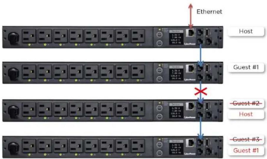
text_image
Ethernet Host Guest #1 Guest #2 Host Guest #3 Guest #1In the above example, if the disconnected Ethernet cable is re-connected, will the role of the PDU/ATSs stay the same?
Yes, when the disconnected cable between Guest 1 and 2 is re-connected, Guest 2 and 3 will revert to their previous roles.
What happens if one PDU/ATS in the daisy-chain is powered off?
For example, if four PDU/ATSs are connected and Guest 1 is powered off, an event showing that Guest 1, 2 and 3 are removed will be recorded in the Host PDU/ATS. Guest 2 and 3 will not create another daisy-chain.
Does the Host PDU/ATS record the logs of the Guest PDU/ATSs and itself?
Yes, the Host PDU/ATS records the logs from all Guest PDU/ATSs daisy-chained to it.
Will the Logs of the Guest PDU/ATSs recorded in the Host PDU/ATS be cleared if the Guest PDU/ATSs are removed from the Host PDU/ATS?
No, the Logs of the Guest PDU/ATSs will remain even after the Guest PDU/ATSs are removed.
Does the Host PDU/ATS record the Status Records of the Guest PDU/ATSs and itself?
Yes, the Host PDU/ATS records the Status Records for all the PDU/ATSs in the daisy-chain.
Will the Status Records of the Guest PDU/ATSs logged in the Host PDU/ATS be cleared if the Guest PDU/ATSs are disconnected from the Host PDU/ATS?
Yes, once the Guest PDU/ATSs are removed, the Status Records logged in the Host PDU/ATS will be cleared. As long as the Host PDU/ATS does not connect to other PDU/ATS s, the Status Records of the disconnected PDU/ATS can be displayed when it is re-connected to the Host PDU/ATS. If the Host PDU/ATS connects to different PDU/ATS s, the Status Records of the removed PDU/ATS will be entirely cleared.
Are the Guest PDU/ATS s able to connect to the network when they are daisy-chained?
Yes, even when the PDU/ATS s are daisy-chained, the Guest PDU/ATS s are able to connect to the network directly. Note that a Guest PDU/ATS will require having its own Ethernet cable connected to the network.
What will happen if a 5th PDU/ATS is added to a daisy-chain?
The maximum number of PDU/ATS s that can be connected in one daisy-chain is 4. The daisy-chain functionality will not work until the fifth PDU/ATS is removed.
What is the maximum recommended length of the Ethernet cable to daisy-chain the PDU/ATS s? 50 ft (15 m)
Troubleshooting
| Problem | Possible Cause | Solution |
| The PDU/ATS s are connected but the daisy chain function is not working. | -The firmware version does not support daisy chain.-The PDU/ATS s have different firmware version. | Check the firmware version of each PDU/ATS and upgrade to v1.08 or above. |
| I cannot set the EnergyWise configuration for Guest PDU/ATS s. | Only the Host PDU/ATS supports this function. | N/A |
| I cannot set the WoL for Guest PDU/ATS s. | Only the Host PDU/ATS supports this function. | N/A |
Firmware Upgrade
By upgrading the Firmware, you can obtain new features and updates/improvements to existing functionality. To ensure the firmware is kept up to date, please regularly visit our website to see if there is any updated firmware version available. There are three methods for upgrading the PDU/ATS firmware. Please follow the instructions below for the method that is appropriate for your application.
There are two files to update in order to upgrade the firmware version:
* cpsmpdumadata_XXX.bin
* cpsmpdumafw_XXX.bin
Note that the XXX is not part of the file name but is where the version number in the filename is given.
Prior to performing a firmware update, please:
- Download the latest firmware from www.cyberpower.com
- Extract the downloaded firmware file to your local "C:\ drive
Note:
- The FTP service needs to be enabled before attempting to execute a firmware upgrade. Please refer to 5.7 FTP Service to make sure that FTP is enabled.
- Please do not turn the PDU/ATS off when processing the Firmware upgrade. PDU/ATS outlets will remain powered on while the firmware update takes place. Only the PDU/ATS LCD screen will reboot.
- The PDU/ATS LCD screen will reboot during the firmware update process. This DOES NOT cause the PDU/ATS outlets to reboot.
Option 1: Single Device Upgrade via FTP
Use the following steps to upgrade the firmware.
- Open a command prompt window and navigate to "C:\".
- Login to the PDU/ATS with FTP command, type
- Connected to 192.168.22.126.
- 220 CyberPower FTP Server Ready.
- User (192.168.22.126:(none)): cyber
- 331 User name okay, need password.
- Password:
- 230 User logged in, proceed.
- ftp>
- C:\>ftp
- ftp> open 192.168.22.126 21 (for example: 192.168.22.126 is the current IP of
    the PDU/ATS and 21 is the default ftp port for the PDU/ATS)
- Upload the cpsmpdumadata_XXX.bin, type
- ftp > bin
- ftp > put cpsmpdumadata_XXX.bin
- Upgrade complete, type
- ftp > quit
-
The system will reboot after you type "quit". This reboot will take approx. 30 seconds.
-
Login to the PDU/ATS via FTP again, type
- C:\>ftp
- ftp> open 192.168.22.126 21 (for example: 192.168.22.126 is the current IP of
    the PDU/ATS and 21 is the default ftp port for the PDU/ATS)
- Connected to 192.168.22.126.
- 220 CyberPower FTP Server Ready.
- User (192.168.22.126:(none)):cyber
- 331 User name okay, need password.
- Password:
- 230 User logged in, proceed.
- ftp>
- Upload cpsmpdumafw_XXX.bin, type
- ftp > bin
- ftp > put cpsmpdumafw_XXX.bin
- Upgrade complete, type
- ftp > quit
- The system will reboot after you type "quit".
Option 2: Single or Multiple Device Upgrade (recommended)
Use the following steps to upgrade the firmware.
- Install the Power Device Network Utility 2 available for download at www.cyberpower.com
- After installation completes, run the Power Device Network Utility 2.
- Wait for scanning to finish (shown in Figure 1).

text_image
PDNU | Device (17) V2.1.2 Type MAC Address Version Account IP Address DHCP Time All All No records found Scan Scanning H 1 > H 50 Copyright © 2022 Cyber Power Systems, Inc. All rights reserved.Figure 1.
- Check the checkbox to select devices listed in the Operation View (Shown in Figure 2).
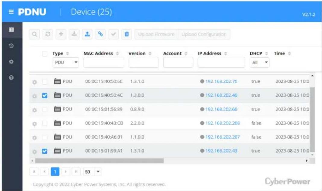
text_image
PDNU Device (25) v2-1.2 Type MAC Address Version Account IP Address DHCP Time PDU PDU 00:0C:15:40:50:6C 1.3.1.0 192.168.202.70 true 2023-08-25 10:0 PDU 00:0C:15:40:50:4C 1.3.0.0 192.168.202.40 true 2023-08-25 10:0 PDU 00:0C:15:01:56:89 0.8.9.0 192.168.202.60 true 2023-08-25 10:0 PDU 00:0C:15:40:43:CB 2.2.0.0 192.168.202.208 false 2023-08-25 10:0 PDU 00:0C:15:40:A6:01 1.1.0.0 192.168.202.207 false 2023-08-25 10:0 PDU 00:0C:15:01:99:A1 1.3.1.0 192.168.202.43 true 2023-08-25 10:0 K < 1 > M 50 Copyright © 2022 Cyber Power Systems, Inc. All rights reserved. CyberPowerFigure 2
- Make sure Account and Password are valid on selected devices (Shown in Figure 3).

text_image
PDNU Device (25) V2.1.2 Upload Firmware Upload Configuration Type PDU Connection Information Account cyber Password ...... DMCP Time All true 2023-08-25 10:0 true 2023-08-25 10:1 true 2023-08-25 10:0 false 2023-08-25 10:0 false 2023-08-25 10:0 保存 Cancel PDU 00:0C:15:01:99:A1 1.3.1.0 cyber 192.168.202.43 true 2023-08-25 10:1 Copyright © 2022 Cyber Power Systems, Inc. All rights reserved. CyberPowerFigure 3.
-
Select Upload Firmware.
-
Click Browse to locate and select the firmware and data file to be updated and then click OK (Shown in Figure 4).

text_image
PDNU Device (25) V2.1.2 Upload Firmware Upload Configuration File Locations of Firmware & Data DHCP Time All PDU Firmware true 2023-08-25 10:0 cpsmpdumafw_131.bin Browse true 2023-08-25 10:1 Data true 2023-08-25 10:0 false 2023-08-25 10:0 false 2023-08-25 10:0 OK Cancel PDU 00:0C:15:01:S9:A1 1.3.1.0 cyber 192.168.202.43 true 2023-08-25 10:1 Copyright © 2022 Cyber Power Systems, Inc. All rights reserved. CyberPowerFigure 4.
- The upgrade progress bar will show in the lower right Upload Firmware window (Shown in Figure 5).
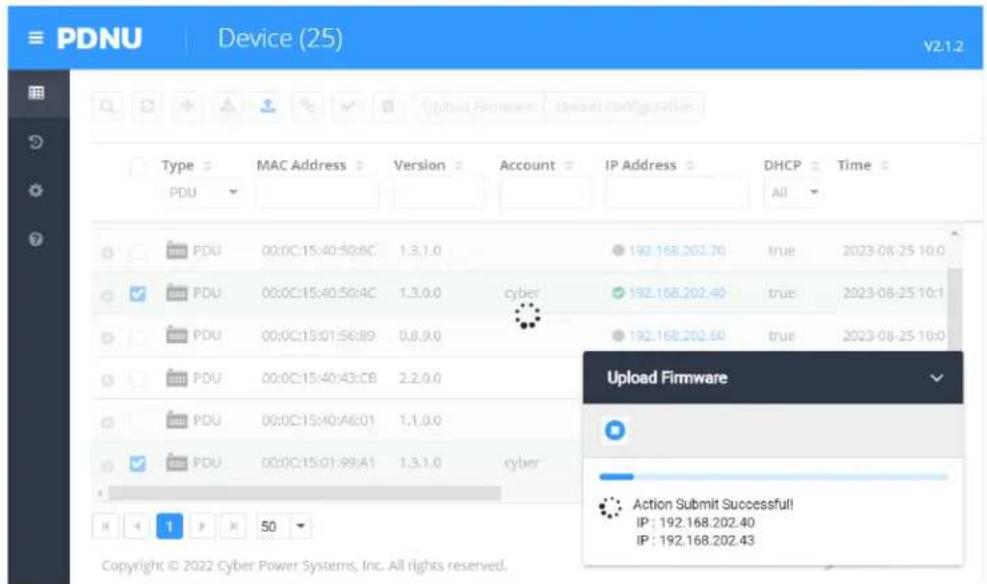
text_image
PDNU Device (25) V2.1.2 Type MAC Address Version Account IP Address DHCP Time PDU PDU 00:0C:15:40:50:6C 1,3,1,0 192.168.202.70 true 2023-08-25 10:0 PDU 00:0C:15:40:50:4C 1,3,0,0 cyber 192.168.202.40 true 2023-08-25 10:1 PDU 00:0C:15:01:56:89 0,8,9,0 192.168.202.60 true 2023-08-25 10:0 PDU 00:0C:15:40:43:CB 2,2,0,0 PDU 00:0C:15:40:A6:01 1,1,0,0 PDU 00:0C:15:01:99:A1 1,3,1,0 cyber Upload Firmware Action Submit Successful! IP : 192.168.202.40 IP : 192.168.202.43 Copyright © 2022 Cyber Power Systems, Inc. All rights reserved.Figure 5.
- The result of firmware upgrade will show in Result column (Shown in Figure 6).
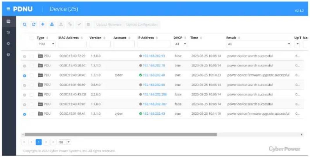
text_image
PDNU Device (25) V2.1.2 Type MAC Address Version Account IP Address DHCP Time Result Up T Na PDU 00:0C:15:40:72:29 1,3,0,0 192.168.202.93 false 2023-08-25 10:06:14 power device search successful 6... PDU 00:0C:15:40:50:6C 1,3,1,0 192.168.202.70 true 2023-08-25 10:06:14 power device search successful 0... PDU 00:0C:15:40:50:4C 1,3,1,0 cyber 192.168.202.40 true 2023-08-25 10:14:23 power device firmware upgrade successful 0... PDU 00:0C:15:01:56:89 0,8,9,0 192.168.202.60 true 2023-08-25 10:06:14 power device search successful 0... PDU 00:0C:15:40:43:CB 2,2,6,0 192.168.202.208 false 2023-08-25 10:06:14 power device search successful 0... PDU 00:0C:15:40:A8:01 1,1,0,0 192.168.202.207 false 2023-08-25 10:06:14 power device search successful 0... PDU 00:0C:15:01:99:A1 1,3,1,0 cyber 192.168.202.43 true 2023-08-25 10:14:19 power device firmware upgrade successful 0... Copyright © 2022 Cyber Power Systems, Inc. All rights reserved. CyberPowerFigure 6.
Note: If you don't want to wait for the firmware upgrade, you can stop the process by clicking Cancel in the lower right Upload Firmware window. However, this is not recommended because the Cancel action may cause the device to malfunction.
Option 3: Use a USB Flash Drive
Use the following steps to upgrade the firmware.
- Download the latest firmware from www.cyberpower.com
- Extract the file to the root directory of a USB flash drive with FAT32 formatting. Please note that the two files below should be available in order to complete the firmware upgrade process:
*cpsmpdumadata_xxx.bin
*cpsmpdumafw_xxx.bin
- Plug the USB drive into the PDU/ATS USB port and press Enter on the PDU/ATS LCD screen to enter Main Menu. The USB option will be displayed.

text_image
Main Menu Alert Meter Control Sensor Setting About USB-
Select USB and press Enter button to enter Firmware Upgrade menu.
-
Select Main and Yes to start the upgrade process.

flowchart
graph TD
    A["USB"] --> B["Firmware Upgrade"]
    B --> C["Main"]
    C --> D["Return"]
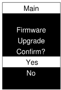
text_image
Main Firmware Upgrade Confirm? Yes No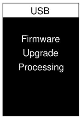
text_image
USB Firmware Upgrade Processing
text_image
USB Firmware Upgrade Success- The PDU/ATS will reboot after the process is completed.
Note: You can check to see if the firmware upgrade is successful by checking the "Firmware version" on the [System->About] webpage. You can also check Firmware Version on LCD screen. Press Enter on the LCD screen to enter Main Menu. Select About and press Enter to see the PDU/ATS information. Select Firmware Version to check the PDU/ATS Firmware Version.
Option 4: Use Secure Copy (SCP) command
Use the following steps to update the firmware via SCP.
Note: Only firmware version 1.10 and above supports the functionality to update firmware via SCP.
For Windows Users:
- Download any PuTTY Secure Copy client (PSCP) utility.
- Save the firmware files and the PSCP Utility in the same folder.
- Open the Command Line Interface and change the path to where the firmware files and the PSCP Utility are saved.
- Enter the following command to perform the firmware update:
pscp -scp
Note:
(5) The SSH setting on the PDU/ATS must be Enabled.
(6)
(7)
(8) Ensure to add “:” after the IP address.
For example:
pscp -scp cpsmpdumafw_XXX.bin cyber@192.168.1.100:
Note: cpsmpdumafw_XXX.bin is the firmware file of the version being updated.
- After executing the command, a message may appear asking if you trust the host. To continue type "y" for yes within 10 seconds.
- On the next screen enter the PDU/ATS password. Please wait until the progress indicator displays 100%. The system will automatically log out and reboot after the transfer is complete.
- Repeat steps 4 through step 6 to upload the firmware file cpsmpdumafw_XXX.bin to complete the firmware update process.
- If the firmware file transfer is unsuccessful you will see an error message. Attempt to retype the command and execute it again.
For Linux, MacOS and Unix Users:
- Install the related distribution of an SSH or SCP client, for example Openssh client.
- Open the Terminal and change the path to where the firmware files are saved.
- Enter the following Command to perform firmware update:
scp@< IP address of PDU/ATS>:
Note:
(1) The SSH setting on the PDU/ATS must be Enabled.
(2)
(3)
(4) Ensure to add “:” after the IP address.
For example:
scp cpsmpdumafw_XXX.bin cyber@192.168.1.100:
Note: cpsmpdumafw_XXX.bin is the firmware file of the version being updated.
- After executing the command, a message may appear asking if you trust the host. To continue type "y" for yes within 10 seconds.
- On the next screen enter the PDU/ATS password. Please wait until the progress indicator displays 100%. The system will automatically log out and reboot after the transfer is complete.
- Repeat steps 3 through step 5 to upload the firmware file cpsmpdumafw_XXX.bin to complete the firmware update process.
- If the firmware file transfer is unsuccessful you will see an error message. Attempt to retype the command and execute it again.
Contact Information
Feel free to contact our Tech Support department with installation, troubleshooting, or general product questions.
Cyber Power Systems, Inc.
Web: www.cyberpower.com
For USA and Canada:
4241 12th Ave East, Suite 400 Shakopee, MN55379
Toll-free: (877) 297-6937
For all other regions:
Please visit our website for local contact information.