MBP63AHVHW82U - Inverter CyberPower - Free user manual and instructions
Find the device manual for free MBP63AHVHW82U CyberPower in PDF.

User questions about MBP63AHVHW82U CyberPower
0 question about this device. Answer the ones you know or ask your own.
Ask a new question about this device
Download the instructions for your Inverter in PDF format for free! Find your manual MBP63AHVHW82U - CyberPower and take your electronic device back in hand. On this page are published all the documents necessary for the use of your device. MBP63AHVHW82U by CyberPower.
USER MANUAL MBP63AHVHW82U CyberPower
natural_image
Illustration of a BYPASS industrial control unit with ports, connectors, and indicator lights (no text or symbols on main body)SAFETY INSTRUCTIONS
SAVE THESE INSTRUCTIONS
This manual contains important instructions. Please read and follow all instructions carefully during installation and operation of the unit. Read this manual thoroughly before attempting to unpack, install, or operate the Maintenance Bypass PDU (MBP).
The SmartApp Online MBP63AHVHW82U models that are covered in this manual are intended for installation in an environment within 32^ F to 104^ F ( 0^ C to 40^ C), free of conductive contaminants.
SPECIAL SYMBOLS

Warning: High voltage - Risk of Electric Shock.

Caution - Important Instructions: Must always be followed.

Information, advice, help.

See applicable user manual.
SAFETY INSTRUCTIONS CONT.
PERSONAL SAFETY
CAUTION

CAUTION - To reduce the risk of fire, connect only to a circuit provided with 40 amperes (5,000 VA) /50 amperes (6,000 VA)/60 amperes (8,000 VA)/75 amperes (10,000 VA) maximum branch circuit overcurrent protection in accordance with the National Electric Code, ANSI/NFPA 70 and the Canadian Electrical Code, Part I, C22.1.
CAUTION! The MBP must be connected to a grounded AC power outlet with a fuse or circuit breaker protection. DO NOT plug the MBP into an outlet that is not grounded.
CAUTION! The MBP should be placed near the connected equipment and easily accessible.
CAUTION! The AC outlet, where the MBP is connected, should be close to the unit and easily accessible.
Do not work alone under hazardous conditions.
Input circuit breaker must be "OFF" during the building installation.
RISK OF ELECTRIC SHOCK
WARNING! To prevent the risk of fire or electric shock, install in a temperature and humidity controlled indoor area, free of conductive contaminants. (Please see specifications for acceptable temperature and humidity range).
WARNING! (No User Serviceable Parts): Risk of electric shock, do not remove the cover. There are no user serviceable parts inside. Seek service from qualified service personnel.
To prevent the risk of fire or electric shock, only use the supplied hardware to attach the mounting brackets.
Remove watches, rings or other metal objects. Use tools with insulated handles.
To prevent the risk of fire or electric shock, install in a temperature and humidity controlled indoor area, free of conductive contaminants. (Please see specifications for acceptable temperature and humidity range).
To avoid electric shock, turn off and unplug the unit before installing the input/output power cord with a ground wire. Connect the ground wire prior to connecting the line wires!
Connect the Protection Earth (PE) safety conductor before any other cables are connected.
SAFETY INSTRUCTIONS CONT.
PRODUCT SAFETY
RISK OF ELECTRIC SHOCK
Maintenance Bypass PDU (MBP) covered in this document are permanently-connected equipment and only qualified maintenance personnel may carry out installations.
Wiring must be done by qualified personnel.
DO NOT USE FOR MEDICAL OR LIFE SUPPORT EQUIPMENT! Under no circumstances should this unit be used for medical applications involving life support equipment and/or patient care.
DO NOT USE WITH OR NEAR AQUARIUMS! To reduce the risk of fire, do not use with or near aquariums. Condensation from the aquarium can come in contact with metal electrical contacts and cause equipment to short out.
The unit has a dangerous amount of voltage.
DO NOT INSTALL THE MBP WHERE IT WOULD BE EXPOSED TO DIRECT SUNLIGHT OR NEAR A STRONG HEAT SOURCE!
DO NOT CONNECT DOMESTIC APPLIANCES SUCH AS HAIR DRYERS TO MBP OUTPUT SOCKETS!
A readily accessible disconnect device shall be incorporated in the building installation wiring for AC Input.
Wiring Information: "Use No. 6 AWG, minimum 90°C copper wire and 18 lb-in Torque force when connecting to AC wiring terminal".
TABLE OF CONTENTS
SAFETY INSTRUCTIONS......II
Special Symbols ......II
Personal Safety....III
Product Safety....IV
INTRODUCTION....1
Maintenance Bypass PDU (MBP)....1
Whats In The Box....3
HARDWARE INSTALLATION 4
Front Panel Description.... 4
Brackets Installation 5
MBP Installation....5
ELECTRICAL INSTALLATION....7
Hardwiring The Input/Output Terminals 7
Operations With MBP Detection Cable Installed....10
Operations To Retain EPO & ROO Function....15
TECHNICAL SPECIFICATIONS....21
INTRODUCTION
The CyberPower Maintenance Bypass PDU (MBP) allows the seamless transfer of an electrical load from UPS power to utility power for uninterrupted operation of connected equipment when performing maintenance, replacing batteries, or installing a new UPS.
The key features include:
• Power Distribution
Delivers AC power to servers, equipment, and connected devices via a power distribution unit.
- Maintenance Bypass
Qualified personnel can use the bypass feature to disconnect the PDU from the UPS without disrupting power to connected equipment. This feature allows connected equipment to operate seamlessly during maintenance periods, battery replacement, or UPS installation.
- Manual Bypass Switch
When the Manual Bypass Switch is turned to Normal, connected equipment is supplied by UPS output. When the Manual Bypass Switch is turned to Bypass, connected equipment is supplied by utility power.
• Durable Metal Housing
Protects internal components and resists damage from impact or abrasions within challenging industrial environments. Also extends the life of the product.
INTRODUCTION CONT.
[NOTE] MBP63AHVHW82U Only with compatible CyberPower UPS.
[NOTE] If the MBP Detection Cable is not used, the Firmware is not required to be updated.
[NOTE] If MBP Detection Cable is installed, the UPS EPO and ROO functions will be disabled.
[NOTE] If MBP Detection Cable is not installed, the UPS will not automatically transfer to bypass mode.
[NOTE] TO AVOID DAMAGE! Read the MBP User Manual before installation and operation for correct operating procedures and to avoid lost power load or UPS damage.
[NOTE] If the UPS is equipped with outlets, those outlets can no longer be used, loads can only be connected to the MBP outlets or the MBP Output terminal blocks.
UPS should be turned off when UPS is doing maintenance, if load connect to UPS outlet, the load will be lost.
Before turn off UPS, MBP need to set to bypass and keep provide power from utility.
INTRODUCTION CONT.
WHATS IN THE BOX

| ITEM | CONTENT QTY | |
| 1 | MBP63AHVHW82U(Maintenance Bypass PDU) | 1 |
| 2 | User's manual | 1 |
| 3 | Rackmount brackets | 2 |
| 4 | Flat head screws: M4X6L (4) | 4 |
| 5 | Pan head screws: M5X8L (4) | 4 |
| ITEM | CONTENT QTY | |
| 6 | Input/output terminal block cover | 2 |
| 7 | Cage nut | 4 |
| 8 | MBP detection cable 3.3ft | 1 |
| 9 | Conduits with internal wires for MBP63AHVHW82U to UPS input / output 3ft | 2 |
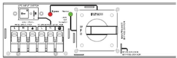
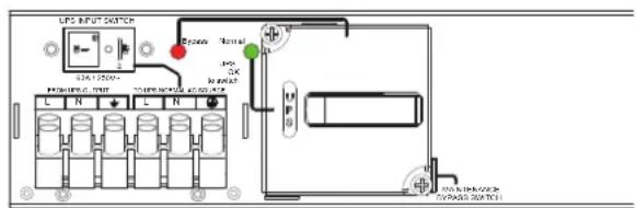
MBP FRONT PANEL DESCRIPTION
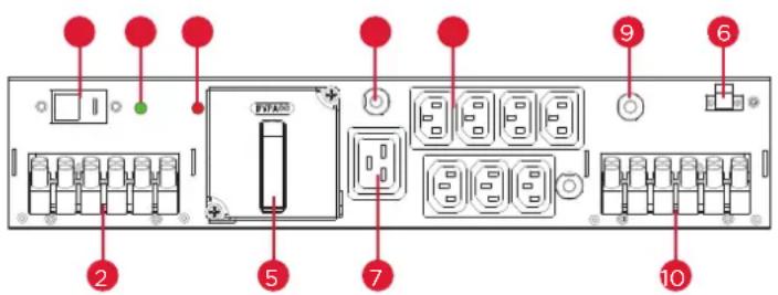
text_image
Diagram of an electronic device rear panel with labeled ports and components, including battery, switches, and indicators.- UPS INPUT SWITCH
- Input/Output terminal blocks connect to UPS
- "Bypass" Red light LED indicator (Bypass source ready)
- "Normal" Green light LED indicator (UPS source ready OK to switch)
- MAINTENANCE BYPASS SWITCH
- 16A circuit breaker for IEC C19 outlet
- EC C19 (1) outlet
- IEC C13 (7) outlet
- 10A circuit breaker for IEC C13 outlet
- Input terminal blocks connect to utility and Output terminal blocks connect to equipment load
- MBP detection port
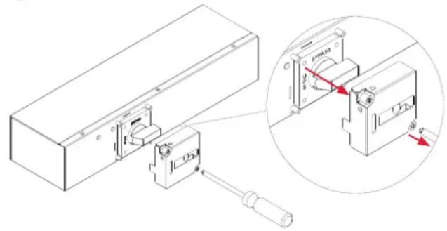
HARDWARE INSTALLATION CONT.
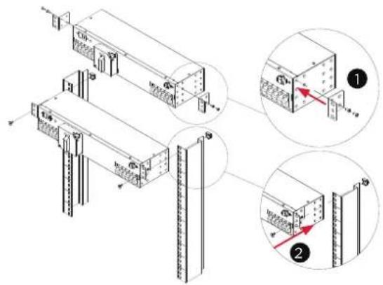
The MBP can be mounted in a rackmount or vertical tower orientation. Please follow the instructions below for the respective mounting methods.
1. Brackets installation
Attach the two brackets to the MBP using the provided screws M4X6L*4pcs.
2. MBP Installation
Secure the MBP to rack, CyberPower rack-mounted UPS or a wall with the provided screws M5X8L*2pcs.
MBP mounted horizontally in a rackmount
text_image
Technical diagram showing structural assembly with labeled components and magnified views of a component detailMBP mounted vertically in a rackmount

text_image
Technical diagram showing three views of a server rack with labeled components and directional arrows indicating assembly or installation steps.
text_image
Technical diagram showing assembly steps of server racks with labeled components and directional arrows indicating movement.HARDWARE INSTALLATION CONT.
1. Brackets installation
Attach the two brackets to the MBP using the provided screws M4X6L*4pcs.
2. MBP Installation
Secure the MBP to rack, CyberPower rack-mounted UPS or a wall with the provided screws M5X8L*2pcs.
MBP mounted horizontally with a CyberPower UPS

text_image
Technical diagram showing a server rack with labeled components and a magnified view of the internal structure.MBP mounted with a CyberPower UPS in tower mode

text_image
Technical diagram of a server rack with labeled components and an inset showing internal wiring connectionsWall-mounted

text_image
Technical diagram of a modular device with labeled components and an inset view showing internal structure details.
Caution: Important Instructions
To prevent the risk of fire or electric shock, only use the supplied hardware to attach the mounting brackets.
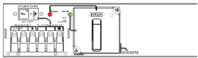
ELECTRICAL INSTALLATION
HARDWIRING THE INPUT/OUTPUT TERMINALS
Important! Set the UPS INPUT switch of the MBP to the "O" off position before hardwire connecting.

text_image
Technical diagram showing electrical panel layout with labeled components and wiring connections, including a close-up of a cable outlet.CONNECT MBP TO UTILITY AND LOAD CONFIGURATION
- Fix the terminal block bottom cover and tighten the two screws to fix the terminal block bottom cover on the MBP.
- Insert the output cable through the appropriate cable gland and connect three wires L, N and Ground to the "OUTPUT" MBP terminal block. (For connection to Load).
- Insert the input cable through the appropriate cable gland and connect the three wires L, N and Ground to the "NORMAL AC SOURCE" MBP terminal blocks. (For connection to Utility).
- Put the terminal block Top cover and tighten the two screws to cover terminal.
- Tighten the cable glands.

text_image
Technical diagram showing a device with labeled components and a magnified view of its internal structure.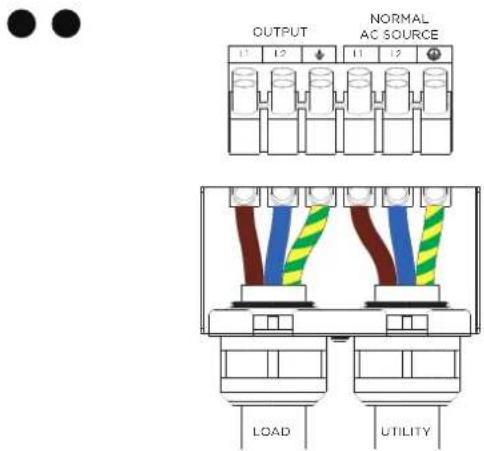
text_image
OUTPUT NORMAL AC SOURCE LOAD UTILITY
natural_image
Technical line drawing of a mechanical component with two curved pipes (no text or symbols)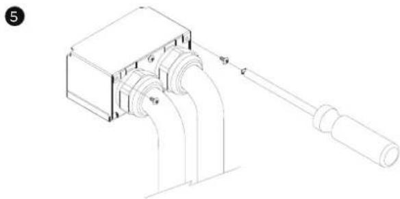
natural_image
Technical line drawing of a mechanical device with pipes and a shaft (no text or symbols)ELECTRICAL INSTALLATION CONT.
CONNECT MBP TO UPS INPUT/OUTPUT CONNECT INTERNAL WIRES THROUGH CONDUITS FOR MBP63AHVHW82U TO UPS
- Separate the top and bottom covers by Loosening the two screws to separate the top and bottom covers.
Fix the terminal block bottom cover and tighten the two screws to fix the terminal block bottom cover on the MBP. - Insert the output cable through the conduits and connect three wires L, N and Ground to the "FROM UPS OUTPUT" terminal block. (For connection to UPS output).
- Insert the input cable through the conduits and connect the three wires L, N and Ground to the "UPS NORMAL AC SOURCE" MBP terminal blocks. (For connection to UPS input).
- Put the terminal block Top cover and tighten the two screws to cover terminal.
- Tighten the cable glands.
1

natural_image
Technical line drawings of three mechanical components: a box, a screwdriver, and a cylindrical component (no text or symbols present)2
4

text_image
FROM UPS OUTPUT TO UPS NORMAL AC SOURCE UPS OUTPUT UPS INPUT●

natural_image
Technical line drawing of a mechanical component with two curved pipes (no text or symbols)●

natural_image
Technical line drawing of a mechanical device with pipes and a shaft (no text or symbols)ELECTRICAL INSTALLATION CONT.
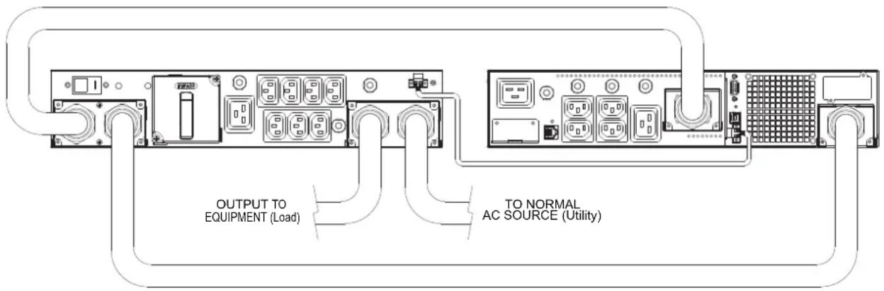
CONNECTING THE MAINTENANCE BYPASS PDU TO A UPS
Connect the input/output as shown in the following diagrams for different models
OL5KERTHD/OL6KERTHD
text_image
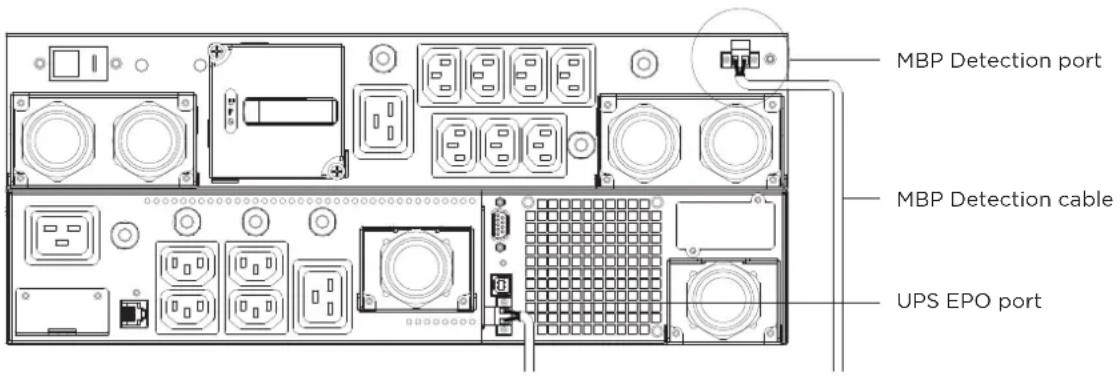
OUTPUT TO EQUIPMENT (Load) TO NORMAL AC SOURCE (Utility)MBP DETECTION CABLE INSTALLATION
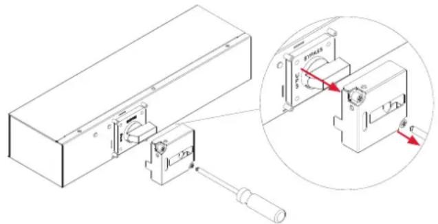
Connect the MBP detection cable to the specific UPS connector.
Important ! Only with compatible CyberPower UPS.
After installing the MBP detection cable to the UPS EPO port, the UPS signal input must be set up for Manual Bypass. Refer to the UPS User Manual as following.
(1) OL5KERTHD/OL6KERTHD models :
Set up→communication→Signal input→Manual Bypass→Save Change?
[NOTE] Verify that the total equipment ratings do not exceed the UPS capacity to prevent an overload alarm.
[NOTE] If MBP Detection Cable is installed, the UPS EPO and ROO functions will be disabled.
[NOTE] If MBP Detection Cable is not installed, the UPS will not automatically transfer to bypass mode.
[NOTE] TO AVOID DAMAGE! Follow the correct operation and start up procedures using either the MBP Detection Cable (P9) or Retaining EPO & ROO Function (P15).
text_image
MBP Detection port MBP Detection cable UPS EPO portELECTRICAL INSTALLATION CONT.
OPERATIONS WITH MBP DETECTION CABLE INSTALLED
UPS START-UP WITH MBP63AHVHW82U AND MBP DETECTION CABLE
[NOTE] If the UPS is equipped with outlets, those outlets can no longer be used, loads can only be connected to the MBP outlets or the MBP Output terminal blocks. UPS should be turned off when UPS is doing maintenance, if load connect to UPS outlet, the load will be lost. Before turn off UPS, MBP need to set to bypass and keep providing power from utility.
- Check that the UPS is correctly connected to the MBP63AHVHW82U (see previous chapter HARDWIRING THE INPUT/OUTPUT TERMINAL connecting the input/output and MBP detection) If the UPS is equipped with outlets, those outlets can no longer be used (loads can only be connected to the MBP outlets or the MBP Output terminal blocks).
- Verify that the MBP terminal blocks are connected to the Normal AC source (Utility).
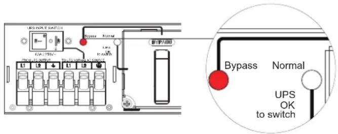
- Release two screws by screw driver and open the Cover of MBP switch and Check that the MBP manual Bypass switch is to the "Bypass" position.
- Set the upstream circuit breaker (not provided) to the "I" on position to switch On the Normal AC source (Utility) power.
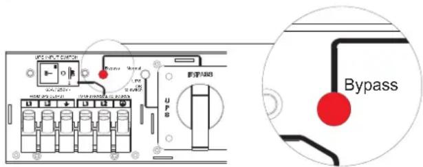
- Verify that the "Bypass" red light of the MBP goes On, indicating that the load is now powered by the Normal AC source (Utility).
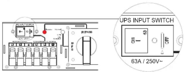
- Set the UPS INPUT switch of the MBP to the "I" on position.
- Verify that the UPS is correctly powered (UPS display panel illuminates).
3
natural_image
Technical diagram of a mechanical assembly with an inset showing internal components (no text or symbols present)5
text_image
UPS 100V, 25V UPS 100V, 25V UPS 100V, 25V UPS 100V, 25V UPS 100V, 25V UPS 100V, 25V UPS 100V, 25V UPS 100V, 25V UPS 100V, -25V UPS 100V, -25V UPS 100V, -25V UPS 100V, -25V UPS 100V, -25V UPS 100V, -25V UPS 100V, -25V UPS 100V, -25V UPS 1O UPS 1B UPS 1C UPS 1D UPS 1E UPS 1F UPS 1G UPS 1H UPS 1I UPS 1J UPS 1K UPS 1L UPS 1M UPS 1N UPS 2A UPS 2B UPS 2C UPS 2D UPS 2E UPS 2F UPS 3A UPS 3B UPS 3C UPS 3D UPS 3E UPS 3F UPS 4A UPS 4B UPS 4C UPS 4D UPS 4E UPS 4F UPS 4G UPS 4H UPS 4I UPS 4J UPS 4K UPS 4L UPS 4M UPS 4N UPS 4O UPS 4P UPS 4Q UPS 4R UPS 4S UPS 4T UPS 4U UPS 4V UPS 4W UPS 4X UPS 4Y UPS 4Z UPS 4A UPS 4B UPS 4C UPS 4D UPS 4E UPS 4F UPS 4G UPS 4H UPS 4I UPS 4J UPS 4K UPS 4L UPS 4M UPS 4N UPS 4O UPS 4P UPS-1A UPS-1B UPS-1C UPS-1D UPS-1E UPS-1F UPS-1G UPS-1H UPS-1I UPS-1J UPS-1K UPS-1L UPS-1M UPS-1N UPS-1O UPS-1P UPS-1Q UPS-1R UPS-1F UPS-1G UPS-1H UPS-1I UPS-1J UPS-1K UPS-1L UPS-1M UPS-1N UPS-1O UPS-1P UPS-1Q UPS-1R UPS-1F UPS-1G UPS-1H UPS - Bypass6
text_image
UPS INPUT SWITCH 63A / 250V~ UPSELECTRICAL INSTALLATION CONT.
UPS START-UP WITH MBP63AHVHW82UAND MBP DETECTION CABLE CONT.
- Important ! The signal input setting of UPS should set to "Manual Bypass" for MBP detection (refer to the UPS user manual as following)
OL5KRTHD/OL6KERTHD models :
Set up→Communication→Signal input→Manual Bypass→Save Change?
[NOTE] If not follow the step to set the UPS Signal input to Manual Bypass function enable and correctly connected MBP detection cable, it will be caused UPS damage.
-
Press the UPS "ON/OFF" power button for 3 seconds to start the UPS.
-
UPS will be automatically turning to "Bypass mode" (MBP detection port should connect to UPS EPO port, see previous chapter HARDWIRING THE INPUT / OUTPUT TERMINAL connecting the input / output and MBP detection cable)
- Verify that the UPS is on Bypass mode by checking UPS display panel (refer to the UPS user manual).
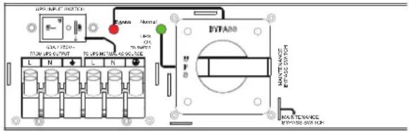
- Verify that the "Normal" green light of the MBP goes On, indicating that the UPS output power is available on the MBP.
Important ! do not continue to next step if the “Normal” green light of the MBP is still Off(the load will be lost).
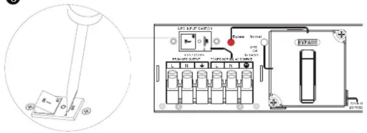
- Set the MBP manual Bypass switch to the "UPS" position: the load is now powered by the UPS.
- Replace the Cover of MBP switch and tighten 2 screws by screw driver, UPS will be automatically turning to Line mode.
- Check that the UPS is in Online mode by checking UPS display panel (refer to the UPS user manual) the load is now protected by the UPS.

text_image
12 UPS INPUT SWITCH BYP/ABB BYP/ABB BYP/ABB BYP/ABB BYP/ABB BYP/ABB BYP/ABB BYP/ABB BYP/ABB BYP/ABB BYP/ABB BYP/ABB BYP/ABB BYP/ABB BYP/ABB BYP/ABB BYP/ABB BYP/ABB BYP/ABB BYP/ABB BYP/ABG BYP/ABG BYP/ABG BYP/ABG BYP/ABG BYP/ABG BYP/ABG BYP/ABG BYP/ABG BYP/ABG BYP/ABG BYP/ABG BYP/ABG BYP/ABG BYP/ABG BYP/ABG BYP/ABG BYP/AK BYP/AK BYP/AK BYP/AK BYP/AK BYP/AK BYP/AK BYP/AK BYP/AK BYP/AK BYP/AK BYP/AK BYP/AK BYP/AK BYP/AK BYP/AK BYP/AK BYP/AK BYP/AK BYP/AK BYP/Ak BYP/Ak BYP/Ak BYP/Ak BYP/Ak BYP/Ak BYP/Ak BYP/Ak BYP/Ak BYP/Ak BYP/Ak BYP/Ak BYP/Ak BYP/Ak BYP/Ak BYP/Ak BYP/Ak BYP/Ak BYP/Ak BYP/Ak BYP/AaAaAaAaAaAaAaAaAaAaAaAaAaAaAaAaAaAaAaAaAaAaAaAaAaAaAaAaAaAaAaAaAaAaAaAaAaAaAaAaAaAaAaAaAaAaAaAaAaAaAa13
text_image
UPS UHV SWITCH 0.5A 125V~ FDC UPG OUTPUT L N L N Epass Name LPS ON 70/MPPT BYPARD MANTENANCE BYPARD OUT FCF14

text_image
UPS INPUT SWITCH 0.541 LPS FROM MFGS, START 70 MPG INCHORS AND SWITCH Control OK No Control Control Control Control Control Control Control Control Control Control Control Control Control Control Control Control Control Control Control Control Control Control Control Control Control Control Control Control Control Control Control Control Control Control Control Control Control Control Control Control Control Control Control Control Control Control Control Control Control Control CUTR/RINJ/REFR STATION SWITCHELECTRICAL INSTALLATION CONT.
UPS REPLACEMENT WITH MBP63AHVHW82U AND MBP DETECTION CABLE
For UPS removal, follow the MANDATORY steps below:
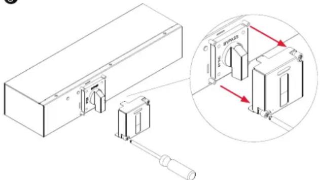
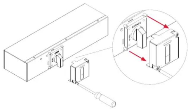
- Release two screws by screw driver and open the Cover of MBP switch, UPS will be automatically turning to "Bypass mode".
- Verify that the UPS is on Bypass mode by checking UPS display panel (refer to the UPS user manual).
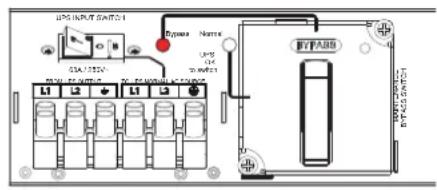
- Set the MBP manual Bypass switch to "Bypass" position, indicating that the load is supplied directly by Normal AC source (Utility) power.
- Replace the Cover of MBP switch and tighten 2 screws by screw driver.
- Press the UPS "ON/OFF" power button for 3 seconds to turn off UPS and make sure UPS is turned in to standby mode and green light of the MBP goes Off.
1
text_image
Technical diagram showing a mechanical assembly with labeled components and a magnified inset highlighting a specific component with red arrows indicating rotation.3

text_image
UPS BUT1 2021-24 IGBT IGBT-A38 U P M1000000000 M1000000000 IGBT-A38 IGBT-A38 IGBT-A38 IGBT-A38 IGBT-A38 IGBT-A38 IGBT-A38 IGBT-A38 IGBT-A38 IGBT-A38 IGBT-A38 IGBT-A38 IGBT-A38 IGBT-A38 IGBT-A38 IGBT-A38 IGBT-A38 IGBT-BUT1 2021-24 IGBT-BUT1 2021-24 IGBT-BUT1 2021-24 IGBT-BUT1 2021-24 IGBT-BUT1 2021-24 IGBT-BUT1 2021-24 IGBT-BUT1 2021-24 IGBT-BUT1 2021-24 A15A15A15A15A15A15A15A15A15A15A15A15A15A15A15A15A15A15A15A15A15A15A15A15A15A15A15A15A15A15A15A15A15A15B4

text_image
LPG FAN10 SWITCH I2A 250V REQUISITION LPG N I2A EFPASS EFPASS SWITCH5
text_image
UPS INPUT SWITCH Bypass Normal USS 100A 200A TICKERS OUTPUT UPS 100A 200A UPS 100A 200A 新开关口 Bypass Normal UPS OK to switchELECTRICAL INSTALLATION CONT.
UPS REPLACEMENT WITH MBP63AHVHW82U AND MBP DETECTION CABLE CONT.
- Set the UPS INPUT switch of the MBP to the "O" off position and wait 90 seconds to make sure UPS is totally shut down.
- UPS stops, the UPS can now be disconnected, as described below:
(1) First opening the I/O terminal blocks cover of UPS, check if hazardous voltage is no longer present on UPS terminal blocks by using an electrical safety tester.
(2) Disconnect the MBP conduits, and the MBP detection cable.
- Replace the UPS
! Hazardous voltage and lost load risk: do not operate the MBP manual Bypass switch without UPS connected to the MBP power conduits.
6
text_image
LPS INPUT SWITCH P-500 12320V 12320V 12320V 12320V 12320V 12320V 12320V 12320V 12320V 12320V 12320V 12320V 12320V 12320V 12320V BYFABO BYFABO7
text_image
UPS INPUT SWITCH CIA 1234 DC 1234 DC 1234 DC 1234 Dyneo Name UPS DC DC BFPADB BFPADB SWITCHRETURN TO NORMAL OPERATION:
- Check that the new UPS is correctly connected to the MBP, as described below:
(1) First check that UPS INPUT switch of the MBP is still locked to the "O" off position.
(2) After opening the UPS I/O terminal blocks cover, connect to UPS the MBP conduits, and the MBP detection cable.
(see previous chapter HARDWIRING THE INPUT/OUTPUT TERMINAL connecting for more details)
- Set the UPS INPUT switch of the MBP to the "I" on position.
- Verify that the UPS is correctly powered (UPS display panel illuminates).
- Important ! The signal input setting of UPS should set to "Manual Bypass" for MBP detection (refer to the UPS user manual as following).
OL5KERTHD/OL6KERTHD models :
Set up → communication → Signal input → Manual Bypass → Save Change?
1
UPS INPUT SWITCH

text_image
N 3 +63A / 250V\~
ELECTRICAL INSTALLATION CONT.
RETURN TO NORMAL OPERATION CONT.:
- Press the UPS "ON/OFF" power button for 3 seconds to turn to start the UPS.
- UPS will be automatically turning to Bypass mode If not, please check MBP detection cable is correctly connected.
- Verify that the UPS is on Bypass mode by checking UPS display panel (refer to the UPS user manual).
- Verify that the "Normal" green light of the MBP goes On, indicating that the UPS output power is available on the MBP.
Important ! do not continue to next step if the “Normal” green light of the MBP is still Off (the load will be lost).
- Release two screws by screw driver and open the Cover of MBP switch and the MBP manual Bypass switch is to the "Bypass" position now.
- Set the MBP manual Bypass switch to the "UPS" position, indicating that the load is now powered by the UPS.
- Replace the Cover of MBP switch and tighten 2 screws by screw driver, UPS will be automatically turning to Line mode.
- Check that the UPS is in Online mode by checking UPS display panel (refer to the UPS user manual) the load is now protected by the UPS.
9
natural_image
Technical line drawing of a mechanical assembly with an inset showing a close-up of a component labeled 'SAC' (no text or symbols present)ELECTRICAL INSTALLATION CONT.
OPERATIONS TO RETAIN EPO & ROO FUNCTION (NO MBP DETECTION CABLE)
UPS START-UP WITH MBP63AHVHW82U
[NOTE] Verify that the total equipment ratings do not exceed the UPS capacity to prevent an overload alarm.
[NOTE] If the MBP Detection Cable is not used, the Firmware is not required to be updated.
[NOTE] If MBP Detection Cable is installed, the UPS EPO and ROO functions will be disabled.
[NOTE] If MBP Detection Cable is not installed, the UPS will not automatically transfer to bypass mode
[NOTE] TO AVOID DAMAGE! Follow the correct operation and start up procedures using either the MBP Detection Cable (P9) or Retaining EPO & ROO Function (P15).

text_image
MBP detection port Remove EBM detection cable UPS EPO port[NOTE] If the UPS is equipped with outlets, those outlets can no longer be used, loads can only be connected to the MBP outlets or the MBP Output terminal blocks. UPS should be turned off when UPS is doing maintenance, if load connect to UPS outlet, the load will be lost.
Before turn off UPS, MBP need to set to bypass and keep provide power from utility.
- Check that the UPS is correctly connected to the MBP63AHVHW82U (see previous chapter HARDWIRING THE INPUT/OUTPUT TERMINAL connecting the input and output but no need to connect MBP detection).
If the UPS is equipped with outlets, those outlets can no longer be used (loads can only be connected to the MBP outlets or the MBP Output terminal blocks).
- Verify that the MBP terminal blocks are connected to the Normal AC source (Utility).
ELECTRICAL INSTALLATION CONT.
UPS START-UP WITH MBP63AHVHW82U CONT.
- Release two screws by screw driver and open the Cover of MBP switch and Check that the MBP manual Bypass switch is to the "Bypass" position.
- Set the upstream circuit breaker (not provided) to the "I" on position to switch On the Normal AC source (Utility) power.
- Verify that the "Bypass" red light of the MBP goes On, indicating that the load is now powered by the Normal AC source (Utility).
- Set the UPS INPUT switch of the MBP to the "I" on position.
- Verify that the UPS is correctly powered (UPS display panel illuminates)
-
Enable EPO or ROO function (refer to the UPS user manual as following) OL5KERTHD/OL6KERTHD models : Set up → communication → Signal input → EPO or ROO → Save Change?
-
Press the UPS "ON/OFF" power button for 3 seconds to start the UPS, UPS will be turning to line mode.
-
UPS should set to bypass mode from LCD Panel (refer to the UPS user manual as following) OL5KERTHD/OL6KERTHD models : Controls→Manual Bypass→Enable→Activate Important ! before setting the UPS to bypass mode, do not set the MBP manual Bypass switch to the "UPS" position. UPS will be damaged if this is not followed.

natural_image
Technical line drawing of a mechanical assembly with an inset close-up showing internal components (no text or symbols)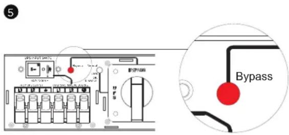
text_image
5 Bypass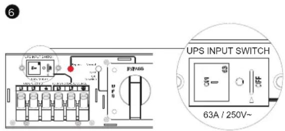
text_image
6 UPS INPUT SWITCH 63A / 250V~ELECTRICAL INSTALLATION CONT.
UPS START-UP WITH MBP63AHVHW82U CONT.
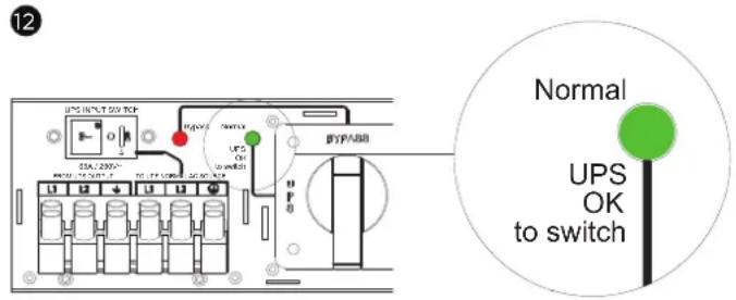
- Verify that the UPS is on Bypass mode by checking UPS display panel (refer to the UPS user manual).
- Verify that the “Normal” green light of the MBP goes On, indicating that the UPS output power is available on the MBP.
Important! do not continue to next step if the "Normal" green light of the MBP is still Off (the load will be lost).
- Set the MBP manual Bypass switch to the "UPS" position: the load is now powered by the UPS.
- Replace the Cover of MBP switch and tighten 2 screws by screw driver, UPS will be automatically turning to Line mode.
- UPS should set back to line mode from LCD Panel (refer to the UPS user manual as following) OL5KERTHD/OL6KERTHD models :
Controls→Manual Bypass→Disable→Activate
Important ! After the MBP manual Bypass is switched to the "UPS" position, UPS should set back to Line mode to protect load.
If not, the load is still supplied directly by Normal AC source (Utility) power.
- Check that the UPS is in Online mode by checking UPS display panel (refer to the UPS user manual) the load is now protected by the UPS.
12
text_image
12 UPS INPUT 057 TCK STA.2395- R45-16-057 UPS OK SWITCH BYP3388 Normal UPS OK to switch13
text_image
I2C-1250-4 I2C-1250-32 L N L R BYFASG I2C-1250-4 I2C-1250-32 BYFASG 3214
text_image
UPS INPUT SWITCH DC1/200+ PUBSING C. UTR L N L N Resistor Normal MAX OK Max Input M M M M M M M M M M M M M M M M M MELECTRICAL INSTALLATION CONT.
UPS REPLACEMENT WITH MBP63AHVHW82U
For UPS removal, followed the MANDATORY steps below:
-
Firstly UPS should set to bypass mode from LCD Panel (refer to the UPS user manual as following) (1) OL5KERTHD/OL6KERTHD models :
Controls → Manual Bypass → Enable → Activate -
Verify that the UPS is on Bypass mode by checking UPS display panel (refer to the UPS user manual) Important ! before setting the UPS to bypass mode, do not set the MBP manual Bypass switch to the "Bypass" position.
UPS will be damaged if this is not followed.
-
Release two screws by screw driver and open the Cover of MBP switch.
-
Set the MBP manual Bypass switch to "Bypass" position, indicating that the load is supplied directly by Normal AC source (Utility) power.
-
Replace the Cover of MBP switch and tighten 2 screws by screw driver.
-
Press the UPS "ON/OFF" power button for 3 seconds to turn off UPS and make sure UPS is turned in to standby mode and green light of the MBP goes Off.
3
natural_image
Technical line drawing of a mechanical assembly with an inset showing a close-up view of a component (no text or symbols present)4

text_image
EVTAB0 ENRASS SWITCH5
text_image
I2S INPUT Switch Exposure Normal LUN R TX 750V/100V DC 50V EIP bus + - + - + - + - + - + -6

text_image
UPG INPUT SWITCH Bypass Normal UPS OK to switch BIP/SSS UPS OR to switch Bypass Normal UPS OK to switchELECTRICAL INSTALLATION CONT.
UPS REPLACEMENT WITH MBP63AHVHW82U CONT.
- Set the UPS INPUT switch of the MBP to the "O" off position and wait 90 seconds to make sure UPS is totally shut down.
- UPS stops, the UPS can now be disconnected, as described below:
(1) First opening the I/O terminal blocks cover of UPS, check if hazardous voltage is no longer present on UPS terminal blocks by using an electrical safety tester.
(2) Disconnect the MBP conduits.
- Replace the UPS
7

text_image
UPS INPUT SWITCH 614/250V~ LPS OK to switch LN N TC175-30Hz 45.5G8

text_image
UPS INPUT SWITCH SIA / 1250V- FROM UPS CUTO UT L1 L2 70 UPS NORMAL AC 6.0 MPB L1 L2 Square Normal UPS CK 800mA BYPASS MAINTENANCE BYPASS SWITCH! Hazardous voltage and lost load risk: do not operate the MBP manual Bypass switch without UPS connected to the MBP power conduits.
RETURN TO NORMAL OPERATION:
- Check that the new UPS is correctly connected to the MBP, as described below:
(1) Firstly check that UPS INPUT switch of the MBP is still locked to the "O" off position.
(2) After opening the UPS I/O terminal blocks cover, connect to UPS the MBP conduits but no need to connect MBP detection.
(see previous chapter HARDWIRING THE INPUT/OUTPUT TERMINALS connecting for more details).
- Set the INPUT switch of the MBP to the "I" on position.
- Verify that the UPS is correctly powered (UPS display panel illuminates)
- Enable EPO or ROO function (refer to the UPS user manual as following)
(1) OL5KERTHD/OL6KERTHD models :
Set up → Communication → Signal input → EPO or ROO → Save Change?
1
UPS INPUT SWITCH

natural_image
Pure electrical circuit lines without any symbols63A / 250V\~
ELECTRICAL INSTALLATION CONT.
RETURN TO NORMAL OPERATION CONT.:
- Press the UPS "ON/OFF" power button for 3 seconds to start the UPS, UPS will be turning to line mode.
- UPS should set to bypass mode from LCD Panel (refer to the UPS user manual as following) (1) OL5KERTHD/OL6KERTHD models :
Controls → Manual Bypass → Enable → Activate
Important ! before setting the UPS to bypass mode, do not set the MBP manual Bypass switch to the "UPS" position.
UPS will be damaged if this is not followed.
- Verify that the UPS is on Bypass mode by checking UPS display panel (refer to the UPS user manual).
- Verify that the "Normal" green light of the MBP goes On, indicating that the UPS output power is available on the MBP.
Important ! do not continue to next step if the “Normal” green light of the MBP is still Off (the load will be lost).
- Release two screws by screw driver and open the Cover of MBP switch and the MBP manual Bypass switch is to the "Bypass" position now.
-
Set the MBP manual Bypass switch to the "UPS" position, indicating that the load is now powered by the UPS.
-
Replace the Cover of MBP switch and tighten 2 screws by screw driver.
- UPS should set back to line mode from LCD Panel (refer to the UPS user manual as following) OL5KERTHD/OL6KERTHD models :
Controls → Manual Bypass → Disable → Activate
Important! After the MBP manual Bypass is switched to the "UPS" position, UPS should set back to Line mode to protect load.
If not, the load is still supplied directly by Normal AC source (Utility) power.
- Check that the UPS is in Online mode by checking UPS display panel (refer to the UPS user manual) the load is now protected by the UPS.

text_image
Technical diagram showing a mechanical assembly with labeled components and an inset view of a device with red directional arrows indicating motion or force.TECHNICAL SPECIFICATIONS
MODEL MBP63AHVHW82U
| Input | |
| Input Voltage Range 200-240V | |
| Input Current Rating 63A | |
| Inlet To Utility Power (1) Terminal | Block |
| Inlet To UPS Input (1) Terminal Block | |
| Inlet To UPS Output (1) Terminal | Block |
| Wiring Information Use No. 6 AWG, minimum 90°C copper wire and 18 lb-in | |
| Output | |
| Outlets | (1) IEC C19(7) IEC C13(1) Terminal Block |
| Physical | |
| Form Factor 2U | |
| Enclosure Construction Steel | |
| Dimensions (WxHxD) (in.) 17 x 3.4 x 4.9 | |
| Dimensions (WxHxD) (mm.) | 433 x 86.5 x 125 |
| Weight (lbs.) | 8.8 |
| Weight (kg.) 4 | |
| TO UPS Cord Length | 3ft. |
| Environmental | |
| Operating Temperature | 32°F to 104°F / 0°C to 40°C |
| Operating Relative Humidity | 0% - 90% non-condensing |