FR45608BNI - Lamp Fredrick Ramond - Free user manual and instructions
Find the device manual for free FR45608BNI Fredrick Ramond in PDF.

User questions about FR45608BNI Fredrick Ramond
0 question about this device. Answer the ones you know or ask your own.
Ask a new question about this device
Download the instructions for your Lamp in PDF format for free! Find your manual FR45608BNI - Fredrick Ramond and take your electronic device back in hand. On this page are published all the documents necessary for the use of your device. FR45608BNI by Fredrick Ramond.
USER MANUAL FR45608BNI Fredrick Ramond
natural_image
Silhouette of a chandelier with a hanging top and tassel (no text or symbols)MIME
FR45608BNI/FBZ
Bulbs: 6-60W CAND. Replacement Parts: SHADE: R45608SH (BNI FINISH), R455608AMBSII (FBZ FINISII), R45602CRY-A
ASSEMBLY INSTRUCTIONS
Assembly of this fixture will be accomplished by first assembling the main body, installing the mounting hardware to the junction box, hanging the fixture and then installing the shade and crystals.
SAFETY WARNING: Read wiring and grounding instructions [FRIS 18] and any additional directions. Turn power supply off during installation. If new wiring is required, consult a qualified electrician or local authorities for code requirements.
STEP 1
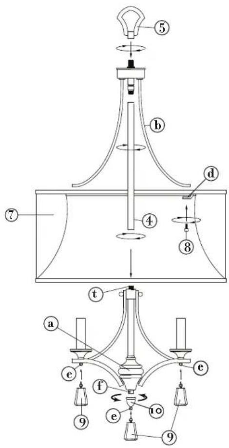
1 Slip center column (4) along wire and thread onto swivel (s) located on the top main body with the three arms (b) - see DRAWING 1.
1 Slip center stem (4) with top main body (b) along wire and thread onto threaded tube (t) located on the top of socket body assembly (a).
2 Slip loop (5) along wire and thread onto top of fixture.
3 Spread arms (b) until they are 60 degrees apart.
4 Fixture is ready for installation.
STEP 2 Refer to Hanging Instruction Sheet [FRIS19] to hang fixture. Then refer back to this sheet to continue installation of this fixture.
STEP 3
Take shade (7) and line up holes in tabs (d) with the holes in end of arms (b). Shade tab should be on top of the arm.
2 Slip ball knob stud (8) through hole in shade tab and thread it into arm (b). Repeat process with the remaining shade tabs.
3 Next thread knob (10) onto threaded tube (f). Then attach crystals (9) to loop (e).
[DRAWTING 1]
text_image
Technical diagram of a mechanical device with numbered components and directional arrows indicating motion or force.
FREDRICK RAMOND
ESTABLISHED 1965
A Division of Hinkley Lighting, Inc.
33000 PIN OAK PARKWAY | AVON LAKE, OHIO 44012 toll free 800.446.5539 | phone 440.653.5500
FRIS19
HANGING INSTRUCTIONS
SAFETY WARNING: Read wiring and grounding instructions [FRIS 18] and any additional directions. Turn power supply off during installation. If new wiring is required, consult a qualified electrician or local authorities for code requirements.
STEP 1
1 Shut off electrical current before starting. If the fixture you are replacing is turned on and off by a wall switch, simply turn the switch off. If not, remove the appropriate fuse (or open the circuit breakers) until the fixture is dead. • DO NOT restore current - either by fuse, breaker or switch - until the new fixture is completely wired and in place.
STEP 2
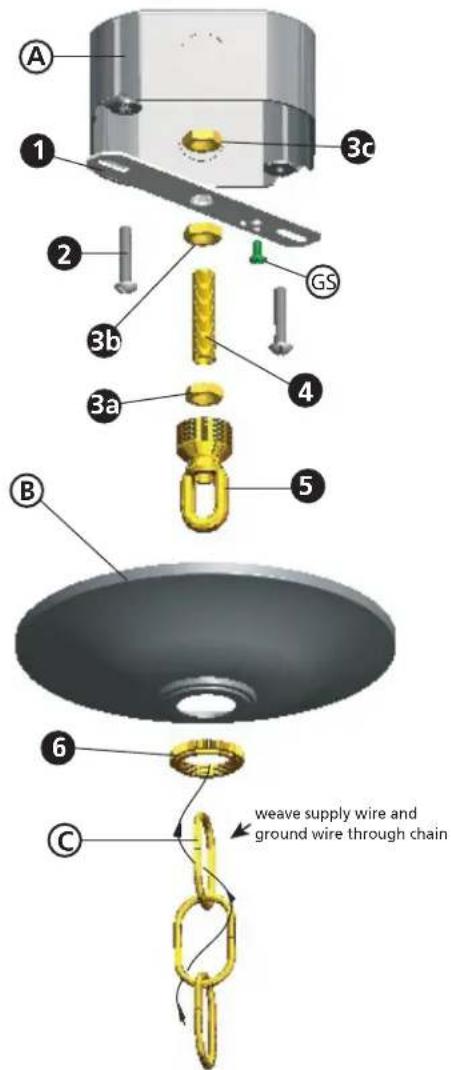
1 Fasten mounting strap (1) to outlet box (A) with the two 8-32 screws (not provide) (2) - see Drawing 1.
2 Thread 2 - hex nuts (3a) and (3b) onto threaded tubing (4).
3 Thread one end of threaded tubing (4) into loop (5) a minimum of 1/2" to 3/4". Thighten hexnut (3a) against loop (5) to lock loop in position.
4 Thread other end of threaded tube (4) into mounting strap approximately 1/2".
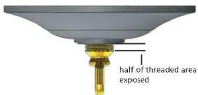
5 Slip canopy (B) over loop (5) and adjust height of loop so half of the threaded area on the loop is exposed - see Drawing 2 below. After loop height is adjusted, thigten hex nut (3b) up against mounting strap, tighten against mounting strap to lock in position.
6 Remove mounting strap (1) from junction box (A), and thread third hex nut (3c) onto end of threaded tube (4), above the mounting strap (1), tighten against mounting strap to lock assembly in position.
7 Remount mounting strap to junction box.
STEP 3
1 Taking the chain, determine the length you require to hang the fixture.
2 Attach one end of the chain to the top loop of the fixture - see Drawing 2.
3 Now slip loop collar (6) and canopy (B) onto chain (C).
4 Attach other end of chain to loop (5). Get assistance for this step since fixture may be heavy and difficult to hold while attaching the chain.
STEP 4
1 Unwrap supply wire and ground wire and weave them up through the chain.
2 Slip supply wire and ground wire through center of loop (5).
3 Connect ground wire to mounting strap (1) using green ground screw (GS).
4 Make electrical connections from supply wire to fixture lead wires. Refer to instruction sheet [FRIS18] and follow all instructions to make all necessary wiring connections.
5 Slip canopy up firmly against the ceiling and secure by turning the threaded loop collar (6) onto loop (5) until tight.
[DRAWING 1]
text_image
A 1 2 3a 3b 3c GS 4 5 B 6 C weave supply wire and ground wire through chain|DRAWING 2|
text_image
half of threaded area exposed
FREDRICK RAMOND
ESTABLISHED 1965
A Division of Hinkley Lighting, Inc.
33000 PIN OAK PARKWAY | AVON LAKE, OHIO 44012
toll free 800.446.5539 | phone 440.653.5500
FRIS18
WIRING AND GROUNDING INSTRUCTIONS
SAFETY WARNING:
Read wiring and grounding instructions
[FRIS 18] and any additional directions. Turn power supply off during installation. If new wiring is required, consult a qualified electrician or local authorities for code requirements.
STEP 1 WIRING INSTRUCTIONS
Indoor Fixtures
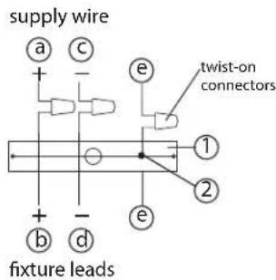
1 Connect positive supply wire (a) (typically black or the smooth, unmarked side of the two-conductor cord) to positive fixture lead (b) with appropriately sized twist on connector - See Drawings 1 or 2.
2 Connect negative supply wire (c) (typically white or the ribbed, marked side of the two-conductor cord) to negative fixture lead (d).
3 Please refer to the grounding instructions below to complete all electrical connections.
Outdoor Fixtures
1 Connect positive supply wire (a) (typically black or the smooth unmarked side of the two-conductor cord) to positive fixture lead (b) with appropriately sized twist on connector - See Drawings 2 or 3.
2 Connect negative supply wire (c) (typically white or the ribbed, marked side of the two-conductor cord) to negative fixture lead (d).
3 Cover open end of connectors with silicone sealant to form a watertight seal.
• If installing a wall mount fixture, use caulk to seal gaps between the fixture mounting plate (backplate) and the wall. This will help prevent water from entering the outlet box. If the wall surface is lap siding, use caulk and a fixture mounting platform specially.
4 Please refer to the grounding instructions below to complete all electrical connections.
STEP 2 GROUNDING INSTRUCTIONS
Flush Mount Fixtures
For positive grounding in a 3-wire electrical system, fasten the fixture ground wire (e) (typically copper or green plastic coated) to the fixture mounting strap (1) with the ground screw (2) - See Drawing 1.
Note: On straps for screw supported fixtures, first install the two mounting screws in strap.
Any remaining tapped hole may be used for the ground screw.
Chain Hung Fixtures
Loop fixture ground wire (e) (typically copper or green plastic coated) under the head of the ground screw (2) on fixture mounting strap (1) and connect to the loose end of the fixture ground wire directly to the ground wire of the building system with appropriately sized twist-on connectors - See Drawing 2.
Post-Mount Fixtures
Connect fixture ground wire (e) (typically copper or green plastic coated) to power supply ground with appropriately sized twist-on connector inside post. Cover open end of connector with silicone sealant to form a watertight seal - See Drawing 3.
[drawing 1]

text_image
supply wire a c e + - ① ② + - b d twist-on connectors fixture leads[drawing 2]
text_image
supply wire a + c - e twist-on connectors 1 2 + d fixture leads e[drawing 3]

text_image
supply wire a c + - b d fixture leads e twist-on connectors e
FREDRICK RAMOND
ESTABLISHED 1965
A Division of Hinkley Lighting, Inc. 33000 PIN OAK PARKWAY | AVON LAKE, OHIO 44012 toll free 800.446.5539 | phone 440.653.5500