AXDSPX-A2B1 - Audio/Video Electronics AXESS - Free user manual and instructions
Find the device manual for free AXDSPX-A2B1 AXESS in PDF.

User questions about AXDSPX-A2B1 AXESS
0 question about this device. Answer the ones you know or ask your own.
Ask a new question about this device
Download the instructions for your Audio/Video Electronics in PDF format for free! Find your manual AXDSPX-A2B1 - AXESS and take your electronic device back in hand. On this page are published all the documents necessary for the use of your device. AXDSPX-A2B1 by AXESS.
USER MANUAL AXDSPX-A2B1 AXESS
natural_image
Product assembly of an electronic device with various colored connectors and connectors (no visible text or labels)INTERFACE COMPONENTS
- AXDSPX-A2B1 interface
- AXDSPX-A2B1 harness
- AXDSPX-A2B1 interface harness (male connectors: 12-pin, 16-pin)
- Amplifier bypass harness (female connectors: 16-pin, 16-pin)
- Radio T-harness
- AXBK-1
A2B Data Interface with Amplifier Bypass Harness & DSP Visit Axxessinterfaces.com for current application list
Visit MetraOnline.com and Axxessinterfaces.com for harness and interface options.
INTERFACE FEATURES
- Designed for Sony A2B amplifiers
- A2B data interface with AXDSP-X (digital signal processor) built-in
- Includes an amplifier bypass harness
- Retains factory chimes including parking sensor chimes
- Retains SYNC voice prompts
- All chimes/voice prompts go through the aftermarket amplifier and/or cluster
- Adjustable chime level
- Micro-B USB updatable
Metraonline.com

For Dash Disassembly Instructions, refer to Metraonline.com. Enter the year, make, and model of the vehicle in the Vehicle Fit Guide for Radio Install kits.
TABLE OF CONTENTS
Connections....2-3
Installation 4
LED Feedback 6
TOOLS REQUIRED
- Crimping tool and connectors, or solder gun, solder, and heat shrink • Tape • Wire cutter
- Zip ties
Google Play Store

Apple App Store
iOS 12.1 or higher

ATTENTION: With the key out of the ignition, disconnect the negative battery terminal before installing this product. Ensure that all installation connections, especially the air bag indicator lights, are plugged in before reconnecting the battery or cycling the ignition to test this product.
NOTE: Refer also to the instructions included with the aftermarket radio.
CONNECTIONS TO BE MADE AT THE FACTORY AMPLIFIER'S LOCATION

flowchart
graph TD
A["Factory Amp Harness"] --> B["A2B-EXT Extension Cable"]
B --> C["AXDSP Input Harness"]
C --> D["12-Pin"]
D --> E["AX8X-1"]
E --> F["Remote Bass Knob Level Control for Ch5 and Ch6"]
F --> G["To Aftermarket Amplifiers"]
G --> H["Channel Programming is done through the AXDSP-XL App"]
H --> I["RCA Jacks (sold separately)"]
I --> J["Blue/White - Amp Turn-On Wire"]
J --> K["Red/White - Not Used"]
K --> L["AXDSP-A2B1 Interface"]
L --> M["NOT USED"]
M --> N["AXDSP Input Harness"]
N --> O["AXDSP Input Harness"]
O --> P["Factory Amp (must be removed)"]
P --> Q["Factory Amplifier Locations"]
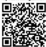
Q --> R["Please see Speaker Assignment QR Code located on the back page of instructions."]
CONNECTIONS TO BE MADE AT THE FACTORY RADIO'S LOCATION (CONT)
Wire Insertion View
Viewed from where the wires go into the connector
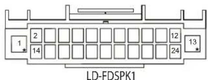
text_image
LD-FDSPK122 Pin
Interface kit includes a T-harness to tap into the speakers powered from the vehicle radio chassis
Factory Radio Harness

natural_image
Cross-sectional illustration of a black cable with internal fins and a wavy line indicating a cable or wire (no text or symbols)NOTE: For Factory Amplifier Locations, please see Speaker Assignment QR Code located on the back page of these instructions.
Run speaker wires to aftermarket amplifier(s)
Located Behind Dash
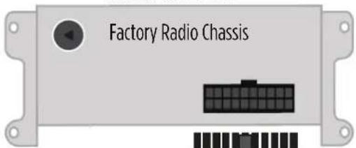
text_image
Factory Radio ChassisT-Harness Installation Location

To OE Speakers
INSTALLATION
- Locate the factory amp ( ^+ ), unplug all connectors, then remove the amp.
- Install the AXDSPX-A2B1 harness and make all necessary connections, but leave the amp turn-on wire disconnected.
Note: Ensure the USB connector from the factory amp is connected to the AXDSPX-A2B1.
- Plug the 12-pin and 16-pin connectors from the AXDSPX-A2B1 harness into the AXDSPX-A2B1 interface.
- Download and install the AXDSP-X app from the Google Play Store or Apple App Store.
- Open the app and follow the instructions on the Bluetooth Connection tab to pair the mobile device to the AXDSPX-A2B1. (Figure A)
- Scroll to the Configuration tab then select the vehicle type. Press the Lock Down button to save the configuration. (Figure B)
- Connect the amp turn-on wire from the AXDSPX-A2B1 harness.
- Click the Identify button to confirm that the AXDSPX-A2B1 is connected properly. If so, a chime will be heard from the front left speaker or gauge cluster. Test all functions of the installation for proper operation.
- Adjust the DSP settings in the app as desired. Refer to the instructions under the Setup Instructions tab, or online at Axxessinterfaces.com for an explanation of each tab in the app.
Note: In these vehicles the factory radio powers some speakers.
Escape: Front tweeters / Center channel
Fusion: Front tweeters / Front center channel / Rear center channel
(†) Amplifier Location
Escape: Behind the left rear quarter panel
Fusion: Behind the right rear quarter panel

text_image
Not Connected SETUP INSTRUCTIONS BLUETOOTH CONNECTION CONFIGURATION INPUTS CROSSOVER ADJUST EQUALIZER ADJUST DELAY ADJUST LEVELS SCAN DISCONNECT Available Devices To connect to the AX-DSP make sure the ignition is in the on position and the AX-DSP is powered up. Hit the SCAN Button and select your AX-DSP from the available devices. Conformation that you are connected to the DSP will show in the top left corner of your screen. To disconnect from the AX-DSP hit the Disconnect button.(Figure A)

text_image
SELECT Vehicle Type and OE Amp Option Make: Ford Model: With OE Amp Without OE AMP APPLY CANCEL OKDOWN Starts the current configuration into the AX-DSP SAVE CONFIG Saves the current configuration to your device RECALL CONFIG Recalls a configuration from your device Applies the recalled configuration to the AX-DSP ABOUT Displays information about this App and the AX-DSP(Figure B)
A2B LED FEEDBACK
| LED FEEDBACK | 1 blink every 5 seconds = All good |
| 2 blinks every 5 seconds = No A2B signal | |
| 3 blinks every 5 seconds = No CAN communication |
Visit AxxessInterfaces.com for more detailed information about the product and up-to-date vehicle specific applications
Speaker Assignment
Having difficulties? We're here to help.
Contact our Tech Support line at:
386-257-1187
Or via email at: techs
techsupport@metra-autosound.com
Tech Support Hours (Eastern Standard Time)
Monday - Friday: 9:00 AM - 7:00 PM
Saturday: 10:00 AM - 5:00 PM
Sunday: 10:00 AM - 4:00 PM

Metra recommends MECP certified technicians