99-5847CH - Unspecified AXESS - Free user manual and instructions
Find the device manual for free 99-5847CH AXESS in PDF.

User questions about 99-5847CH AXESS
0 question about this device. Answer the ones you know or ask your own.
Ask a new question about this device
Download the instructions for your Unspecified in PDF format for free! Find your manual 99-5847CH - AXESS and take your electronic device back in hand. On this page are published all the documents necessary for the use of your device. 99-5847CH by AXESS.
USER MANUAL 99-5847CH AXESS
natural_image
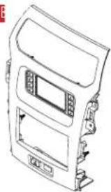
Interior view of a car dashboard with air conditioner and display screens (no visible text or symbols)Ford Explorer (with 4.2-inch touchscreen) 2011-2019
Visit MetraOnline.com for more detailed information about the product and up-to-date vehicle specific applications
KIT FEATURES
• ISO DIN radio provision with pocket
- ISO DDIN radio provision
- Touchscreen display for climate and personalization features
- Integrated hazard button and passenger airbag indicator
- Painted Charcoal Grey
KIT COMPONENTS
• A) Radio/Display trim panel with touchscreen display • B) Radio brackets • C) Pocket • D) (4) #8 x 3/8" Phillips screws for pocket
- E) (2) #4 x 1/2" Phillips screws for A/C Vent to Housing • F) (2) Panel clips • G) Antenna adapter and harnesses (not shown)
AB
natural_image
Line drawing of a car front panel with control buttons and a central touchscreen display (no text or symbols)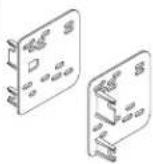


F
TOOLS REQUIRED
- Panel removal tool • Phillips screwdriver • 9/32" Socket wrench • Torx screwdriver
TABLE OF CONTENTS
Dash Disassembly....2
Kit Preparation....3
Kit Assembly
-ISO DIN radio provision with pocket....3
-ISO DDIN radio provision ....3
Final Assembly 8
Axxess Interface Installation 4-13
WIRING & ANTENNA CONNECTIONS
Wiring Harness: Axxess interface built into kit
- Antenna Adapter: Included with kit
• USB retention sold separately. AX-FDUSBAUX for 2015-2019, AXFD-USB3 for 2011-2014.
ATTENTION: With the key out of the ignition, disconnect the negative battery terminal before installing this product. Ensure that all installation connections, especially the air bag indicator lights, are plugged in before reconnecting the battery or cycling the ignition to test this product.
NOTE: Refer also to the instructions included with the aftermarket radio.
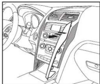
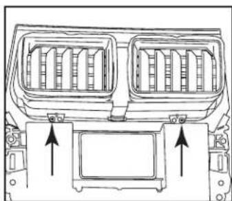
DASH DISASSEMBLY
- Unclip and remove the (2) trim panels from the left and right side of the factory radio. (Figure A)
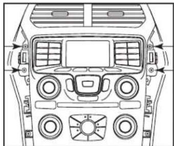
- Remove (4) 9/32" screws securing the radio/climate control panel to the dash. (Figure B)
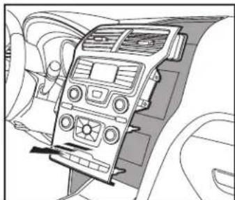
- Unclip, unplug, and remove the factory radio/climate control panel. (Figure C)
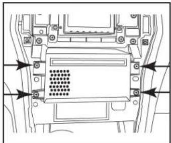
- Remove (4) 9/32" screws securing the radio chassis, then unplug and remove. (Figure D)
- Remove (4) 9/32" screws securing the factory display, then unplug and remove. (Figure E)
Continue to Kit Preparation
natural_image
Interior view of a car dashboard and steering wheel (no text or symbols visible)(Figure A)
natural_image
Top-down technical diagram of a car dashboard and steering wheel (no text or labels)(Figure B)
natural_image
Interior view of a car dashboard with air conditioners and steering wheel (no text or symbols visible)(Figure C)
natural_image
Technical line drawing of a mechanical component with mounting holes and a central grid-patterned chamber (no text or symbols)
natural_image
Technical line drawing of a vehicle chassis frame with mounting brackets and structural components (no text or symbols)(Figure E)(Figure D)
KIT ASSEMBLYKIT PREPAR
- Remove (2) Torx screws securing the a/c vents to the factory radio/climate control panel, then unclip and remove them from the panel. (Figure A)
- Attach the a/c vents to the radio trim panel using the (2) #4 x 1/2" Phillips screws provided with the kit.
- Attach the panel clips provided with the kit onto the radio trim panel. The factory clips may also be used if desired.
Continue to Kit Assembly
natural_image
Technical line drawing of a vehicle air intake system with two vent grilles and mounting brackets (no text or symbols)(Figure A)
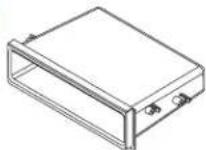
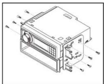
ISO DIN radio provision with pocket
- Secure the pocket to the radio brackets using the (4) #8 x 3/8" Phillips pan head screws supplied. (Figure A)
- Remove the metal DIN sleeve and trim ring from the aftermarket radio.
- Slide the radio between radio brackets, then secure with the screws supplied with the radio. (Figure A)
Continue to Axxess Interface Installation
text_image
Technical diagram of a device with labeled ports and internal components, showing directional arrows for ports A1, A2, A3, A4, and P.(Figure A)
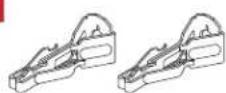
ISO DDIN radio provision
- Secure the radio to the radio brackets using the screws supplied with the radio. (Figure A)
Continue to Axxess Interface Installation

natural_image
Technical line drawing of an electronic device housing with mounting brackets and connectors (no text or symbols)(Figure A)
AXXESS INTERFACE INSTALLATION
INTERFACE FEATURES
- Provides accessory power (12-volt 10-amp)
• Retains R.A.P. (retained accessory power) - Provides NAV outputs (parking brake, reverse, speed sense)
• Retains audio controls on the steering wheel - Retains SYNC ^x
- Retains the factory backup camera
- Retains balance and fade
- Micro-B USB updatable
TABLE OF CONTENTS
Connections....5-6
Installation 7
Initializing the interface....8
Final assembly 8
Extra features (SYNC) 8
Touchscreen display operation 9-10
Steering wheel control settings....11-12
Troubleshooting....13
INTERFACE COMPONENTS
- Axxess interface (built into the touchscreen display)
- 5847 harness
• 16-pin harness with stripped leads
• 12-pin backup camera harness
• 4-pin harness with yellow RCA jacks - Hazard harness
• Female 3.5mm connector with stripped leads
TOOLS REQUIRED
- Wire cutter
- Crimp tool
- Solder gun
- Tape
- Connectors (example: butt-connectors, bell caps, etc.)
CONNECTIONS
From the 16-pin harness with stripped leads to the aftermarket radio:
- Connect the (2) Red wires to the accessory wire.
- If equipped with a factory subwoofer, connect the Blue/White wire to the amp turn on wire.
- If the aftermarket radio has an illumination wire, connect the Orange/White wire to it.
- If the aftermarket radio has a mute wire, and the vehicle is equipped with SYNC ^ , connect the Brown wire to it. If the mute wire is not connected, the radio will turn off when SYNC ^ is activated.
- Connect the Gray wire to the right front positive speaker output.
- Connect the Gray/Black wire to the right front negative speaker output.
- Connect the White wire to the left front positive speaker output.
- Connect the White/Black wire to the left front negative speaker output.
- Tape off and disregard the following (4) wires, they will not be used in this application: Green, Green/Black, Purple, Purple/Black
The following (3) wires are only for multimedia/navigation radios that require these wires.
- Connect the Blue/Pink wire to the VSS/speed sense wire.
- Connect the Green/Purple wire to the reverse wire.
- Connect the Light Green wire to the parking brake wire.
- Black wire to the ground wire.
- Yellow wire to the battery wire.
- Green wire to the left rear positive speaker output.
- Green/Black wire to the left rear negative speaker output.
- Purple wire to the right rear positive speaker output.
- Purple/Black wire to the right rear negative output.
- Tape off and disregard the following (1) wire, it will not be used in this application: Blue
- For models with SYNC ^ : Connect the Red and White RCA jacks labeled "RSE/SYNC/SAT" to the audio AUX-IN jacks of the aftermarket radio.
- For models without SYNC ^ : Connect the Red and White RCA jacks labeled "FROM 3.5" to the audio AUX-IN jacks of the aftermarket radio.
- Disregard the DIN jack, it will not be used in this application.
From the 5847 harness to the aftermarket radio, connect:
Continued on the next page
CONNECTIONS (CONT.)
3.5mm jack steering wheel control retention:
- The 3.5mm jack is to be used to retain audio controls on the steering wheel control.
- For the radios listed below, connect the included female 3.5mm connector with stripped leads, to the male 3.5mm SWC jack from the 5847 harness. Any remaining wires tape off and disregard:
- Eclipse: Connect the steering wheel control wire, normally Brown, to the Brown/White wire of the connector. Then connect the remaining steering wheel control wire, normally Brown/White, to the Brown wire of the connector.
• Metra OE: Connect the steering wheel control Key 1 wire (Gray) to the Brown wire. - Kenwood or select JVC with a steering wheel control wire: Connect the Blue/Yellow wire to the Brown wire.
Note: If your Kenwood radio auto detects as a JVC, manually set the radio type to Kenwood. See the instructions under changing radio type.
• XITE: Connect the steering wheel control SWC-2 wire from the radio to the Brown wire.
- Parrot Asteroid Smart or Tablet: Connect the 3.5mm jack into the AX-SWC-PARROT (sold separately), and then connect the 4-pin connector from the AX-SWC-PARROT into the radio.
Note: The radio must be updated to rev. 2.1.4 or higher software.
- Universal "2 or 3 wire" radio: Connect the steering wheel control wire, referred to as Key-A or SWC-1, to the Brown wire of the connector. Then connect the remaining steering wheel control wire, referred to as Key-B or SWC-2, to the Brown/White wire of the connector. If the radio comes with a third wire for ground, disregard this wire.
Note: After the interface has been programmed to the vehicle, refer to the manual provided with the radio for assigning the SWC buttons. Contact the radio manufacturer for more information.
- For all other radios: Connect the 3.5mm jack into the port on the radio designated for an external steering wheel control interface. Refer to the manual provided with the radio if in doubt as to where the 3.5mm jack goes to.
12-pin backup camera harness:
For models with a 4.2-inch display screen:
- Use the 12-pin backup camera harness.
There are two different methods for connecting the factory backup camera.
If retaining the camera to the aftermarket radio is desired:
- Connect the Yellow RCA jack the backup camera input of the aftermarket radio.
If retaining the camera to the touchscreen display is desired:
- Connect the Yellow RCA jack, to the Yellow RCA jack from the 4-pin harness with yellow RCA jacks labeled "Rearview camera".
Note: If this method is chosen, the backup camera option must be enabled in the Configuration Settings Screen.
4-pin harness with yellow RCA jacks:
- If retaining the factory backup camera to the touchscreen display is desired, connect the Yellow RCA jack labeled "Rearview camera", to the Yellow RCA jack from the 12-pin or 54-pin backup camera harness.
- Disregard the Yellow RCA jack labeled "AUX video", it will not be used in this application.
INSTALLATION
It is highly advisable to read the following steps beforehand, to ensure a clear understanding of what is to be expected. The following steps must be done in the order that they are numbered.
With the vehicle completely off:
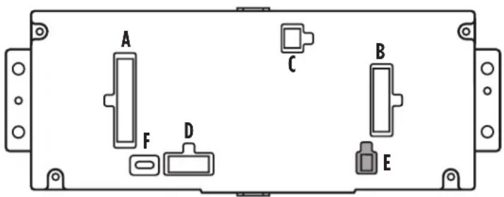
- Connect the 16-pin harness with stripped leads into port "B" in the touchscreen display.
- Connect the 5847 harness to the wiring harnesses in the vehicle. These harnesses are the ones removed in step 4 of dash disassembly. Then insert the 5847 harness into port "A" in the touchscreen display. But do not install this harness until exactly before step 1 of "Initializing the Interface". This is a timed process.
- Connect the 4-pin harness with yellow RCA jacks into port "C" in the touchscreen display.
- Connect the hazard harness into port "D" in the touchscreen display, then to the wiring harness in the vehicle. This is the harness removed in step 3 of dash disassembly.
- Disregard port "E", it will not be used in this application.
- Port "F" is an update port for future firmware upgrades.
text_image
A C B F D EPROGRAMMING FINAL ASSEM
Attention! If the interface loses power for any reason, the following steps will need to be performed again.
- Refer to step 2 of "Installing the interface".
- Place the vehicle ignition to the on position.
- Program the kit:
a. Once the touchscreen display loads up, select the vehicle type; "Ford Explorer 2011-2015".
b. Wait until the radio comes on, and the touchscreen display shows "SWC Configured*". This process may take up to 3 minutes.
Note: If the touchscreen display does not load up, or the radio doesn't come on within 3 minutes, and/or the touchscreen display does not show "SWC Configured*", turn the vehicle off and disconnect the harness from port "A" in the touchscreen display. Check all the connections, reconnect the harness into the touchscreen display, and then try again.
* For models with steering wheel controls.
- Test all functions of the installation for proper operation, before reassembling the dash.
Y
- Secure the completed assembly into the dash using the factory hardware.
- Snap the radio trim panel with touchscreen display over the completed assembly, and then reassemble the dash in reverse order of disassembly.
EXTRA FEATURES
SYNC:
If the vehicle is equipped with SYNC, the 99-5847CH can retain this feature.
- Change the source of the radio to AUX-IN.
- Press the "Info" button on the touchscreen display to enter the SYNC menu. Press the "HVAC" button to get back to the main menu.
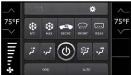
Manual climate controls
text_image
75°F AVE MAX RECBC FRONT REAR 75°F SYNC AUTOAutomatic climate controls
- This is the HVAC control screen which will be displayed on the touchscreen display. This is considered the main screen.
- The upper left tab with (3) arrows will take you to the Heated/Cooled seats screen, if applicable.
Note: This screen will also include Heated Steering if applicable.
- The upper right tab with the gear icon will take you to the Configuration Settings screen.
- Auto climate models: The climate controls will function in the same manner that they did with the factory climate controls.
- Manual climate models: The climate controls will function in the same manner that they did with the factory climate controls, yet via touchscreen buttons instead. The temperature control will display a numerical scale, with "LO" being the coldest, and "HI" being the hottest: L0 / 1-9 / HI
Note: The "Info" button will only be shown if SYNC is to be retained.
Continued on the next page
Configuration Settings screen

text_image
Configuration Settings Backlight Backup Camera Steering Wheel Controls System Config- Backlight
- Four slide bars control the color of the buttons and the back-light intensity: Red / Green / Blue / Backlight
- Backup Camera
- Enable – Enables the backup camera image to the touchscreen display - Disable – Disables the backup camera image to the touchscreen display (default)
- Steering Wheel Controls
- Remap Buttons – For remapping the steering wheel control buttons - Dual Assign – For dual assigning the steering wheel control buttons (long button press) - Select Radio – For auto detecting the radio, or changing the radio type
Touchscreen calibration
- Press and hold the upper two soft buttons on either side of the touchscreen for 10 seconds.
• A screen will pop up asking for you to press the target in the screen.
• After pressing the target with your finger, the calibration process will be complete, and the screen will disappear.
STEERING WHEEL CONTROL SETTINGS
Select Radio screen
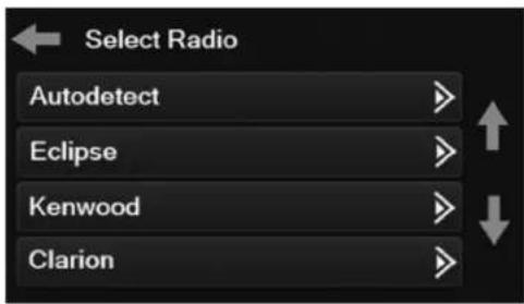
text_image
Select Radio Autodetect Eclipse Kenwood Clarion- To show which brand radio is "auto detected" to the interface, press the "Autodetect" button. The radio detected will have a filled in circle. If the incorrect radio is shown, select the proper radio.
- Following is a list of radio manufacturers that the interface presently acknowledges. Others may be added at a later date. Universal "2 or 3 wire" radios can show up as any of these radio manufacturers.
| Eclipse (type 1) (a) | Eclipse (type 2) (a) |
| Kenwood (b) | LG |
| Clarion (type 1) (a) | Parrot (d) |
| Boss (type 1) / Dual / Sony (a) -Boss only | XITE |
| JVC | Philips |
| Pioneer/Jensen | JBL |
| Alpine (c) | Insane Audio |
| Visteon / Boss (type-4) (a)-Boss only | Magnadyne |
| Valor | Boss (type-3) (a) |
| Clarion (type 2) (a) | Axxera (resistive SWC) |
| Boss (type-2) / Metra OE | Axxera (data SWC) (e) |
(a) If no SWC, change the radio type to the opposite radio type.
(b) If the interface shows JVC, change the radio type to Kenwood.
(c) If an Alpine radio isn't installed, make sure the 3.5mm jack is plugged in.
(d) AX-SWC-PARROT required (sold separately). Radio software must be at least 2.1.4.
(e) Indicated by an SWC wire labeled "IR".
STEERING WHEEL CONTROL SETTINGS (CONT.)
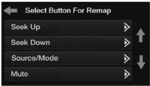
Remap Button screen Dual Assign screen
text_image
Select Button For Remap Seek Up Seek Down Source/Mode Mute- The interface has the ability to change the button assignment for the steering wheel control audio buttons, except Volume-Up and Volume-Down. Follow the prompts on the touchscreen display to remap the steering wheel control audio button(s) to your liking.
Note: The aftermarket radio may not have all of these commands. Please refer to the manual provided with the radio, or contact the radio manufacturer, for specific commands recognized by that particular radio.

text_image
Select Button for Dual Assign Seek Up Seek Down Source/Mode Mute- The interface has the capability to assign two functions to a single button, except Volume-Up and Volume-Down. Follow the prompts on the touchscreen display to program the button(s) to your liking.
Note: Seek-Up and Seek-Down come programmed as Preset-Up and Preset-Down for a long button press.
TROUBLESHOOTING
Resetting the interface
Option #1
- With everything connected and the car running.
- Hold the bottom (2) buttons for 3 seconds, then release. (Figure A) (The screen will turn black and then put you in the vehicle selection screen)
- Select your vehicle and wait till the "SWC Configured" appears on the screen.
- Turn ignition off and start vehicle, then test your interface.
Option #2
- With the vehicle running, press the Reset Vehicle Type button mentioned in System Configuration.
- Refer to Programming, step 3, from this point.

natural_image
Close-up of a control panel with multiple buttons and a blank screen (no visible text or symbols)(Figure A)
Having difficulties? We're here to help.
Contact our Tech Support line at:
386-257-1187
Or via email at: techs
techsupport@metra-autosound.com
Tech Support Hours (Eastern Standard Time)
Monday - Friday: 9:00 AM - 7:00 PM
Saturday: 10:00 AM - 7:00 PM
Sunday: 10:00 AM - 4:00 PM

Metra recommends MECP certified technicians