99-2023BR - Kit d'installation automobile AXESS - Free user manual and instructions
Find the device manual for free 99-2023BR AXESS in PDF.

User questions about 99-2023BR AXESS
0 question about this device. Answer the ones you know or ask your own.
Ask a new question about this device
Download the instructions for your Kit d'installation automobile in PDF format for free! Find your manual 99-2023BR - AXESS and take your electronic device back in hand. On this page are published all the documents necessary for the use of your device. 99-2023BR by AXESS.
USER MANUAL 99-2023BR AXESS
natural_image
Interior view of a car dashboard with air conditioners, steering wheel, and digital display (no readable text or symbols)Buick Regal 2011-2012
Visit MetraOnline.com for up-to-date vehicle specific applications.
KIT FEATURES
- ISO DIN Head unit provision with pocket
- DDIN Head unit provisions
• 99-2023B - Painted Black to match factory finish
• 99-2023BR - Painted Brown to match factory finish
TOOLS REQUIRED
- Panel removal tool - Phillips screwdriver - Socket Wrench
KIT COMPONENTS
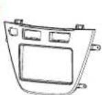
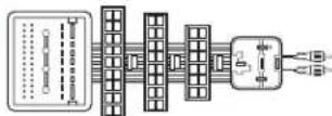
• A) Radio Trim Panel • B) Radio Brackets • C) Pocket • D) Climate Control Trim Ring • E) Climate Control Trim Panel • F) Data Interface
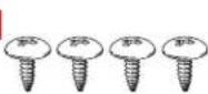
• G) Interface Harness • H) (2) #8 x 3/8" Pan-head Phillips screws • I) (4) #8 x 3/8" Truss-head Phillips screws • J) Switch Blank Plate
A
B

C

D

E

F

[Non-Text]
G
H

1
J

TABLE OF CONTENTS
Dash Disassembly 2
Radio Panel Assembly....3
Climate Control Panel Assembly 3
ISO DIN head unit provisions 4
DDIN head unit provisions 4
Axxess interface installation 5-7
WIRING & ANTENNA CONNECTIONS
Wiring Harness: • Included with kit Antenna Adapter: • 40-EU55 - amplified antenna adapter (sold separately)
ATTENTION: With the key out of the ignition, disconnect the negative battery terminal before installing this product. Ensure that all installation connections, especially the air bag indicator lights, are plugged in before reconnecting the battery or cycling the ignition to test this product. NOTE: Refer also to the instructions included with the aftermarket radio.
DASH DISASSEMBLY
- Unsnap and remove the pocket/ashtray assembly. (Figure A)
- Unsnap and remove the trim above the glove box. (Figure B)
- Unsnap and remove the trim between the radio and steering wheel. (Figure C)

natural_image
Interior view of a car gear shift lever and seatbelt mechanism (no text or symbols)(Figure A)
natural_image
Interior view of a car dashboard and steering wheel (no text or symbols visible)(Figure B)

natural_image
Diagram of a car interior showing steering wheel, dashboard, and seatbelt mechanism (no text or symbols)(Figure C)
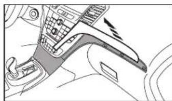
- Unsnap and remove the vent/ screen panel above the radio. (take caution not to cycle the key with this panel unplugged) (Figure D)
- Remove four 7mm screws to remove radio face and climate controls. (Figure E)
- Remove four 7mm screws to remove the radio chassis. (Figure F)
Continue to Kit Assembly

natural_image
Diagram of a car interior showing dashboard, steering wheel, and air vent (no text or labels)(Figure D)

natural_image
Interior view of a car showing dashboard, steering wheel, and dashboard panel (no text or symbols visible)(Figure E)

natural_image
Technical line drawing of a mechanical assembly with no visible text or symbols(Figure F)
RADIO PANEL ASSEMBLY
-
Unsnap the climate controls, traction control switch, park assist switch and start/stop switch (if equipped) from the factory radio panel. (Figure A)
-
Snap the switches into the Metra kit panel. Note: If no start/stop switch is present use the supplied switch blank plate.
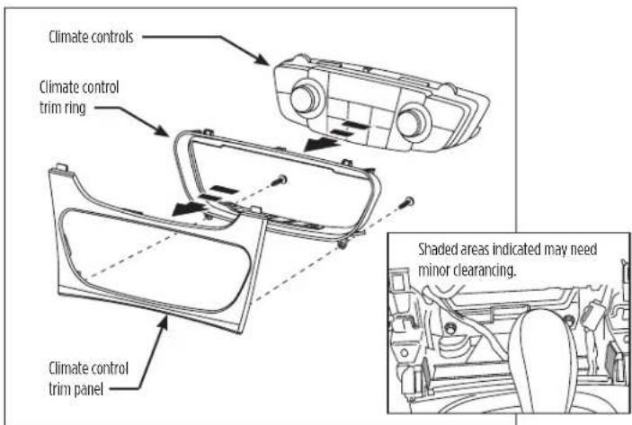
CLIMATE CONTROL PANEL ASSEMBLY
- Snap the climate control in the climate control panel.
Note: Minor sub dash modification may be necessary to allow for clearance of the climate control (See inset). (Figure B)

text_image
Parking Assist switch Traction Control switch Start/Stop switch Climate Controls(Figure A)
text_image
Climate controls Climate control trim ring Climate control trim panel Shaded areas indicated may need minor clearinging.(Figure B)
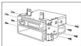
ISO DIN HEAD UNIT PROVISION WITH POCKET
- Mount the radio to the brackets with the screws included with unit. (Figure A)
- Mount the pocket to the radio brackets with the screws supplied. (Figure A)
- Locate the factory wiring harness and antenna plug in the dash. Metra recommends using the proper mating adapters from Metra and/or AXXESS.
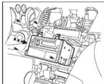
- Mount assembly into the sub dash. (Figure B)
- Reassemble dash in reverse order of disassembly using 99-2022 trim panel instead of factory panel.
Continue to Interface Installation
text_image
Technical diagram of an electrical enclosure with labeled components and internal wiring connections(Figure A)
natural_image
Technical line drawing of an internal mechanical or electronic component with no visible text or symbols(Figure B)
DOUBLE DIN HEAD UNIT PROVISIONS
- Mount the radio to the DDIN brackets with screws included with unit. (Figure A)
- Locate the factory wiring harness and antenna plug in the dash. Metra recommends using the proper mating adapters from Metra and/or AXXESS.
- Mount assembly into the sub dash. (Figure B)
- Reassemble dash in reverse order of disassembly using 99-2022 trim panel instead of factory panel.
Continue to Interface Installation

natural_image
Technical line drawing of a mechanical component with mounting holes and internal structure (no text or symbols)(Figure A)

natural_image
Technical line drawing of a vehicle interior with no visible text or symbols(Figure B)
AXXESS INTERFACE INSTALLATION
TABLE OF CONTENTS
Connections
From 16-Pin Harness....6
From 16-Pin Harness with Nav 6
From 44-Pin Harness....6
From 18-Pin Harness....6
Adjustment Settings
Chime Volume Adjustment 7
Onstar® Level Adjustment 7
Testing the Interface....7
12-Pin SWC Adjustment 7
Personalization Menu 7
TOOLS REQUIRED
- Crimping tool and connectors, or solder gun, solder, and heat shrink
- Tape
• Female Spade Connectors (Optional)
Important: Before beginning any of the following, disconnect the negative battery terminal to prevent an accidental short circuit.
The included interface with this kit is designed to retain Onstar ^® , and retain factory warning chimes, and keep the factory climate display active. It also provides a 12-volt accessory output, mute, park brake, speed signal and reverse output.
CONNECTIONS
From the 16-pin harness, connect as indicated:
• Red wire to the ignition/accessory wire
- Orange/White wire to the illumination wire of the aftermarket radio
If the aftermarket radio has no illumination wire just tape off the Orange/White wire
- Blue/White wire to the amp turn-on wire of the aftermarket radio
- White wire to the left front positive speaker output of the aftermarket radio
- White/Black wire to the left front negative speaker output of the aftermarket radio
- Gray wire to the right front positive speaker output of the aftermarket radio
- Gray/Black wire to the right front negative speaker output of the aftermarket radio
- Green wire to the left rear positive speaker output of the aftermarket radio
- Green/Black wire to the left rear negative speaker output of the aftermarket radio
- Purple wire to the right rear positive speaker output of the aftermarket radio
- Purple/Black wire to the right rear negative output of the aftermarket radio
- Brown wire to the mute wire of the aftermarket radio
If the aftermarket radio does not have a Mute wire, tape up the Brown wire
The following wires on the 16-pin harness are for the aftermarket radios with navigation built in. Connect as indicated:
• Light Green wire to the parking brake wire of the aftermarket navigation radio
- Blue/Pink wire to the VSS or speed sense wire of the aftermarket navigation radio
- Green/Purple wire to the reverse wire of the aftermarket navigation radio
From the 44-pin harness, connect as indicated:
- Yellow wire to the 12-volt constant/battery wire of the aftermarket radio
- Black wire to the ground wire of the aftermarket radio
• The RCAs to the AUX input of your aftermarket radio
From the 18-pin harness, connect as indicated:
- Black wire with the ring terminal to the radio chassis (This wire must be grounded here by itself for the interface to work properly)
- Black/Yellow wire and additional 12-pin harness will be discussed later in this manual
- Connect the RCAs to the AUX input of your aftermarket radio (if equipped)
ADJUSTMENTS
Chime Volume Adjustment
To adjust the chime volume, use a small screwdriver to rotate the potentiometer, located on the 16-pin harness side of the interface. Rotate clockwise to make the chime louder, and counterclockwise to make the chime softer.
Onstar ^® Level Adjustment
To adjust the Onstar® volume level find the Black/Yellow wire on the 22-pin harness.
Push the blue Onstar® button, while the voice is speaking tap the Black/Yellow wire to ground.
There are 4 volume settings for Onstar ^® ; once the 4th setting is reached and the Black/Yellow wire is tapped to ground it will automatically go back to the first volume setting.
Once the volume is set it will stay at that volume until the Black/Yellow wire is tapped to ground again.
This can be set during installation and then left alone.
If user adjustment is desired, the customer may also tap volume up or down to adjust the Onstar ^® level.
Additional 12-pin harness Steering Wheel Control Interface (SWC)
- This 12-pin harness is to be used in conjunction with the SWC (not included). Please refer to the Steering Wheel Control Interface instructions for programming.
Testing the Interface
- Turn the ignition on, and then turn the aftermarket radio on.
- Push the Onstar ^® button, the radio should turn off and you should hear Onstar ^® . Push the Onstar ^® cancel button and the radio should come back on.
Personalization Menu
Note: Vehicle must have steering wheel controls from the factory
- Turn off your aftermarket radio.
- Press and hold off hook for 3 seconds. After 3 seconds the personalization menu will show up on the display.
- To scroll through the menu's use seek up and down
- To make a selection, use the Source button which is the center button between seek up and down.
- Use off hook to exit the personalization menu
Note: Personalization menu can be set before the factory radio is removed.
Having difficulties? We're here to help.
Contact our Tech Support line at:
386-257-1187
Or via email at: techs
techsupport@metra-autosound.com
Tech Support Hours (Eastern Standard Time)
Monday - Friday: 9:00 AM - 7:00 PM
Saturday: 10:00 AM - 5:00 PM
Sunday: 10:00 AM - 4:00 PM

Metra recommends MECP certified technicians