
I43-SERIAL-ETHERNET - AV Accessory StarTech.com - Free user manual and instructions
Find the device manual for free I43-SERIAL-ETHERNET StarTech.com in PDF.


| Product Type | RS232 Serial Over IP Device Server |
| Model | I43-SERIAL-ETHERNET |
| Brand | StarTech.com |
| Serial Ports | 1 x DB-9 RS-232 |
| Ethernet Port | 1 x RJ-45 10/100 Mbps |
| Power Input | 5-24V DC, 3A (15W) via terminal block or DC jack |
| Power Adapter | Included universal power adapter |
| Network Protocols | Telnet Server (RFC2217), web interface |
| Management Software | StarTech.com Device Server Manager for Windows (virtual COM port) |
| Mounting Options | DIN rail and wall mount |
| LED Indicators | Power/Status, Link/Activity, Serial TX/RX |
| Compliance | FCC Class B, ICES-003 |
| Default IP | DHCP (factory reset: 192.168.5.252) |
| Default Password | admin |
| Serial Baud Rates | 300 to 921600 bps |
| Data Bits | 7, 8 |
| Parity | None, Even, Odd, Mark, Space |
| Stop Bits | 1, 2 |
| Flow Control | Hardware, Software, None |
| Factory Reset | Press and hold button for 5 seconds |
| Warranty | 2 years |
Frequently Asked Questions - I43-SERIAL-ETHERNET StarTech.com
User questions about I43-SERIAL-ETHERNET StarTech.com
0 question about this device. Answer the ones you know or ask your own.
Ask a new question about this device
Download the instructions for your AV Accessory in PDF format for free! Find your manual I43-SERIAL-ETHERNET - StarTech.com and take your electronic device back in hand. On this page are published all the documents necessary for the use of your device. I43-SERIAL-ETHERNET by StarTech.com.
USER MANUAL I43-SERIAL-ETHERNET StarTech.com
RS232 Serial Over IP Device Server

natural_image
Black rectangular electronic device labeled 'Surfacebox' with two green USB ports and a small green connector (no readable text or symbols beyond branding)123-SERIAL-ETHERNET shown
Actual product may vary from photos
User Manual
SKU#: I23-SERIAL-ETHERNET / I43-SERIAL-ETHERNET
For the latest information and specifications visit
www.StarTech.com/I23-SERIAL-ETHERNET / www.StarTech.com/I43-SERIAL-ETHERNET
Compliance Statements
FCC Compliance Statement
This equipment has been tested and found to comply with the limits for a Class B digital device, pursuant to part 15 of the FCC Rules. These limits are designed to provide reasonable protection against harmful interference in a residential installation. This equipment generates, uses and can radiate radio frequency energy and, if not installed and used in accordance with the instructions, may cause harmful interference to radio communications. However, there is no guarantee that interference will not occur in a particular installation. If this equipment does cause harmful interference to radio or television reception, which can be determined by turning the equipment off and on, the user is encouraged to try to correct the interference by one or more of the following measures:
• Reorient or relocate the receiving antenna
- Increase the separation between the equipment and receiver
- Connect the equipment into an outlet on a circuit different from that to which the receiver is connected
- Consult the dealer or an experienced radio/TV technician for help
Industry Canada Statement
This Class B digital apparatus complies with Canadian ICES-003.
Use of Trademarks, Registered Trademarks, and other Protected Names and Symbols
This manual may make reference to trademarks, registered trademarks, and other protected names and/or symbols of third-party companies not related in any way to StarTech.com. Where they occur these references are for illustrative purposes only and do not represent an endorsement of a product or service by StarTech.com, or an endorsement of the product(s) to which this manual applies by the third-party company in question. Regardless of any direct acknowledgement elsewhere in the body of this document, StarTech.com hereby acknowledges that all trademarks, registered trademarks, service marks, and other protected names and/or symbols contained in this manual and related documents are the property of their respective holders.
PHILLIPS® is a registered trademark of Phillips Screw Company in the United States or other countries.
To view manuals, videos, drivers, downloads, technical drawings, and more visit www.startech.com/support
Safety Statements
Safety Measures
- Wiring terminations should not be made with the product and/or electric lines under power.
- Cables (including power and charging cables) should be placed and routed to avoid creating electric, tripping or safety hazards.
Mesures de sécurité
To view manuals, videos, drivers, downloads, technical drawings, and more visit www.startech.com/support
Table of Contents
Compliance Statements....1
Safety Statements....2
Product Diagram (I23-SERIAL-ETHERNET) ....4
Front View 4
Rear View....5
Product Diagram (I43-SERIAL-ETHERNET) 6
Front View 6
Rear View....7
Product Information 8
Package Contents 8
Installation 8
Default Settings....8
Hardware Installation 9
Software Installation....11
Operation 11
Telnet....11
Use the Software to Discover the Serial Device Server 12
Configure the Serial Port Settings....14
Changing COM Port or Baud Rate in Windows 17
LED Chart 18
To view manuals, videos, drivers, downloads, technical drawings, and more visit www.startech.com/support
Product Diagram (I23-SERIAL-ETHERNET)
Front View

| Component Function | ||
| 1 | Status LED • Refer to LED Chart | |
| 2 | Wall Mounting Bracket Holes | • Used to secure the Serial Device Server to a Wall or Other Surface using appropriate Mounting Hardware |
| 3 | Serial Communication LED Indicators | • Refer to LED Chart |
| 4 | DB-9 Serial Ports | • Connect an RS-232 Serial Device |
| 5 | DIN Rail Mounting Holes (Not Shown) | • Four Holes on the bottom of the Serial Device Server• Used to secure the included DIN Rail Mounting Kit to the Serial Device Server |
To view manuals, videos, drivers, downloads, technical drawings, and more visit www.startech.com/support
Rear View

natural_image
Front view of a black wireless device with ports, connectors, and a green connector (no visible text or symbols)| Component Function | ||
| 1 | Ethernet Port | Connect an Ethernet Cable to the Serial Device ServerSupports 10/100MbpsLink/Activity LEDs: Refer to LED Chart |
| 2 | DC 2-Wire Terminal Block Power Input | Connect a +5V~24V DC Power SourceA minimum of 5V 3A (15W) is required |
| 3 | DC Power Input | Connect the included Power Adapter |
To view manuals, videos, drivers, downloads, technical drawings, and more visit www.startech.com/support
Product Diagram (I43-SERIAL-ETHERNET)
Front View
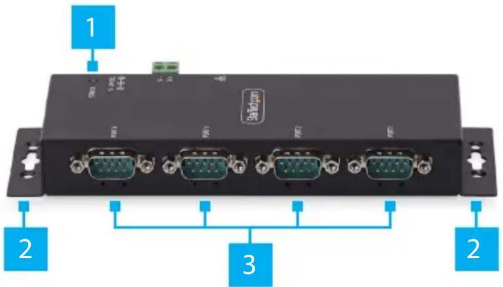
| Component Function | ||
| 1 | Status LED • Refer to LED Chart | |
| 2 | Wall Mounting Bracket Holes | • Used to secure the Serial Device Server to a Wall or Other Surface using appropriate Mounting Hardware |
| 3 | DB-9 Serial Ports | • Connect an RS-232 Serial Device |
| 4 | Serial Communication LED Indicators (Not Labelled) | • Below each DB-9 Port• Refer to LED Chart |
| 5 | DIN Rail Mounting Holes (Not Shown) | • Four Holes on the bottom of the Serial Device Server• Used to secure the included DIN Rail Mounting Kit to the Serial Device Server |
To view manuals, videos, drivers, downloads, technical drawings, and more visit www.startech.com/support
Rear View
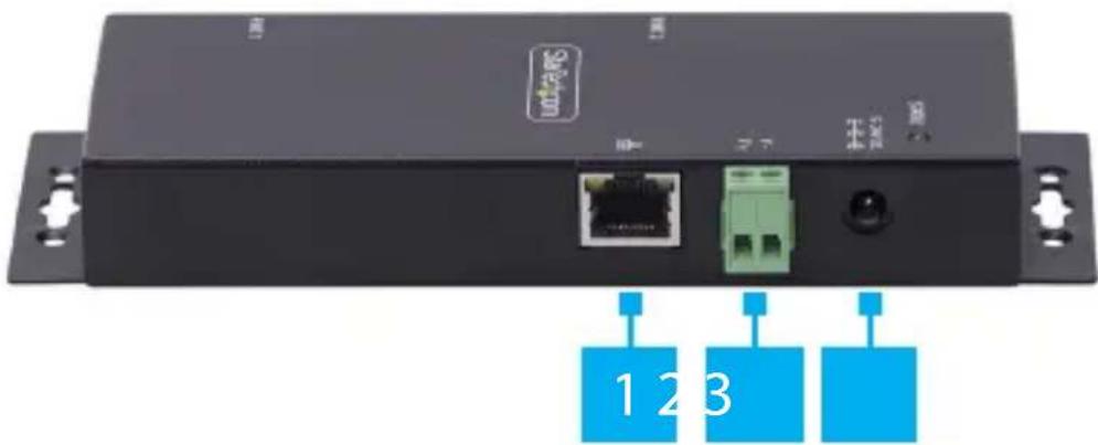
natural_image
Front view of a black wireless device with ports, connectors, and a green port (no visible text or symbols)| Component Function | ||
| 1 | Ethernet Port | Connect an Ethernet Cable to the Serial Device ServerSupports 10/100MbpsLink/Activity LEDs: Refer to LED Chart |
| 2 | DC 2-Wire Terminal Block Power Input | Connect a +5V~24V DC Power SourceA minimum of 5V 3A (15W) is required |
| 3 | DC Power Input | Connect the included Power Adapter |
| 4 | Factory Reset Button(Not Shown) | Resets the Serial Device Server to factory defaultsRefer to Factory Reset Procedure |
To view manuals, videos, drivers, downloads, technical drawings, and more visit www.startech.com/support
Product Information
Package Contents
- Serial Over IP Device Server x 1
- DIN Rail Kit x 1
- Din Rail Screws x 2
• Universal Power Adapter x 1 - Quick-Start Guide x 1
Installation
Default Settings
Out of the Box Settings
• IP Address: DHCP
- Password: admin
• Network Protocol Mode: Telnet Server (RFC2217)
- Serial Mode: RS-232
Factory Default Button Settings
• IP Address: 192.168.5.252
- Password: admin
• Network Protocol Mode: Telnet Server (RFC2217)
- Serial Mode: RS-232
To view manuals, videos, drivers, downloads, technical drawings, and more visit www.startech.com/support
Hardware Installation
(Optional) Configure DB-9 Pin 9 Power
By default, the Serial Device Server is configured with the Ring Indicator (RI) on Pin 9, but it can be changed to 5V DC. To change the DB9 Connector Pin 9 to 5V DC output, please follow these steps:
WARNING! Static Electricity can severely damage electronics. Ensure that you are adequately Grounded before you open the device housing or touch the change the jumper. You should wear an Anti-Static Strap or use an Anti-Static Mat when opening the housing or changing the jumper. If an Anti-Static Strap isn't available, discharge any built-up static electricity by touching a large Grounded Metal Surface for several seconds.
- Ensure the Power Adapter and all Peripheral Cables are disconnected from the Serial Device Server.
- Ensure the Terminal Block Connector has been removed from the Serial Device Server.
- Using a Phillips Screwdriver, remove the Screws from the Housing.
Note: Save these to re-assemble the housing after changing the jumper. - Using both hands, carefully open the Housing to expose the Circuit Board inside.
- Identify Jumper #4 (JP4), located inside the Housing next to the DB9 Connector.
- Using a pair of fine-point tweezers or a small flat-head screwdriver, carefully move the jumper to the 5V position.
- Re-assemble the Housing, ensuring the Housing Screw Holes align.
- Replace the Terminal Block Connector and Housing Screws removed in Step 2 and Step 3.
To view manuals, videos, drivers, downloads, technical drawings, and more visit www.startech.com/support
(Optional) Mounting The Serial Device Server With DIN Rail
- Align the DIN Rail Bracket with the DIN Rail Mounting Holes on the bottom of the Serial Device Server.
- Using the included DIN Rail Mounting Screws and a Phillips Head Screwdriver, secure the DIN Rail Kit to the Serial Device Server.
- Insert the DIN Rail Mounting Plate at an angle starting from the Top, then Push it against the DIN Rail.
(Optional) Mounting The Serial Device Server To A Wall Or Other Surface
- Secure the Serial Device Server to the desired Mounting Surface using the appropriate Mounting Hardware (i.e., wood screws) through the Wall Mounting Bracket Holes.
Install the Serial Device Server
- Connect the included Power Supply or a 5V\~24V DC Power Source to the Serial Device Server.
Note: The Serial Device Server can take up to 80 seconds to startup.
-
Connect an Ethernet Cable from the RJ-45 Port of the Serial Device Server to a Network Router, Switch, or Hub.
-
Connect an RS-232 Serial Device to the DB-9 Port on the Serial Device Server.
Software Installation
-
Navigate to: www.StarTech.com/I23-SERIAL-ETHERNET or www.StarTech.com/I43-SERIAL-ETHERNET
-
Click the Drivers/Downloads tab.
-
Under Driver(s), download the Software Package for Windows Operating System.
-
Extract the contents of the downloaded .zip file.
To view manuals, videos, drivers, downloads, technical drawings, and more visit www.startech.com/support
-
Run the extracted executable file to start the software installation.
-
Follow the on screen prompts to complete the installation.
Operation
Note: The devices support features which secure and protect the devices and its configuration using standard/best practices but as these are intended to be used in controlled environments using proprietary software (virtual COM port) and open communication standards (Telnet, RFC2217) which do not encrypt the data they should not be exposed to an unsecure connection.
Telnet
Using Telnet to send or receive data works with any operating system or host device that supports the Telnet protocol. The software for the connected serial peripheral device may require a COM Port or mapped hardware address. To configure this, the StarTech.com Device Server Manager is required, which is only supported on Windows operating systems.
To communicate with the connected Serial Peripheral Device via Telnet, perform the following:
- Open a terminal, command prompt, or third-party software that connects to a Telnet server.
- Type the IP Address of the Serial Device Server.
Note: This can be found using the StarTech.com Device Server Manager for Windows, or by viewing the connected devices on the local network router.
-
Connect to the Serial Device Server.
-
Type in the terminal, command prompt, or third-party software to send commands/data to the Serial Peripheral Device.
To view manuals, videos, drivers, downloads, technical drawings, and more visit www.startech.com/support
Use the Software to Discover the Serial Device Server
- Launch the StarTech.com Device Server Manager.
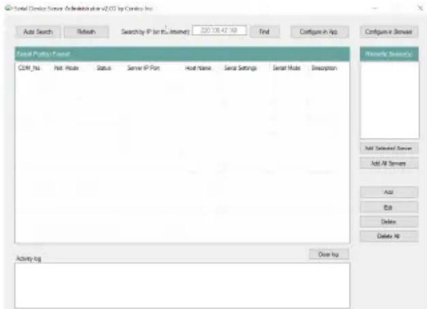
- Click Auto Search to initiate the process of discovering Serial Device Servers on the local network.
- Discovered Serial Device Servers will appear in the "Remote Server(s)" list in the right pane.

To view manuals, videos, drivers, downloads, technical drawings, and more visit www.startech.com/support
- Select "Add Selected Server" to add a specific Serial Device Server or "Add All Servers" to add all discovered Serial Device Servers.

- The Serial Device Servers will be mounted in Device Manager as "SDS Virtual Serial Port" with an associated COM port number.
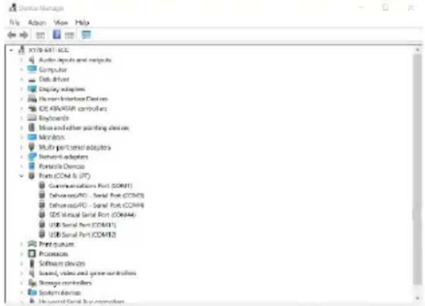
To view manuals, videos, drivers, downloads, technical drawings, and more visit www.startech.com/support
Configure the Serial Port Settings
Available Serial Port Options
| Setting Available Options | |
| Baud Rate | 3006001200180024004800960014400192003840057600115200230400921600 |
| Data Bits | 78 |
| Parity | NoneEvenOddMarkSpace |
| Stop Bits | 12 |
| Flow Control | HardwareSoftwareNone |
To view manuals, videos, drivers, downloads, technical drawings, and more visit www.startech.com/support
In the Software
- Open the StarTech.com Device Server Manager.
- Select "Configure in App" or double click the Serial Device Server in the list.
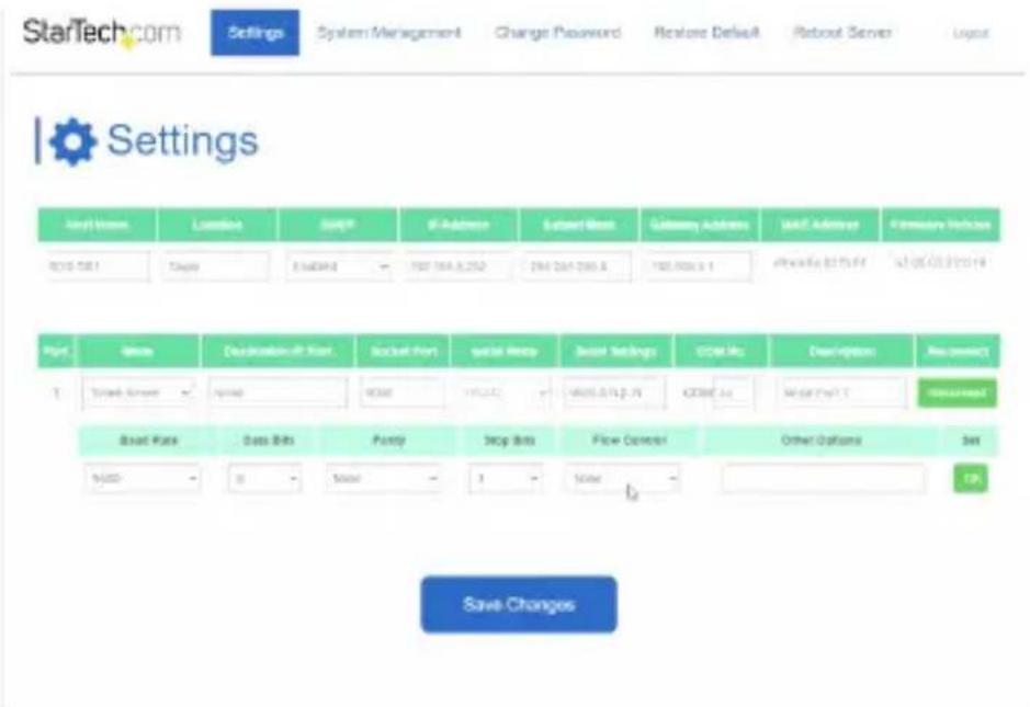
- When the Settings Window opens, use the drop down menus to change Baud Rate, Data Bits, COM Port Number, and more.
Note: If changing the COM Port Number, see "Changing COM Port or Baud Rate in Windows" on Page 15.

- Select "Apply Changes" to save the settings.
To view manuals, videos, drivers, downloads, technical drawings, and more visit www.startech.com/support
In the Web Interface
- Open a web browser.
- Type the IP address of the Serial Device Server into the address bar.
-
Enter the password and select "Login". See Default Password on Page 6.
-
Select the "Serial Settings" to expand the options.
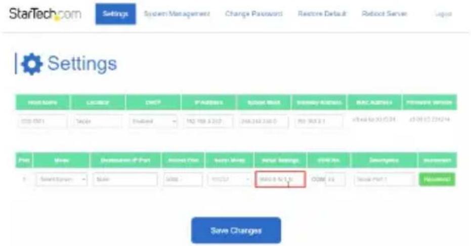
- Use the drop down menus to change Baud Rate, Data Bits, COM Port Number, and more.
To view manuals, videos, drivers, downloads, technical drawings, and more visit www.startech.com/support
- Under "Set", select "OK" to set the serial settings to the port.
- Select "Save Changes" to save the settings to the Serial Device Server.
Changing COM Port or Baud Rate in Windows
To change the COM Port number or Baud Rate in Windows, the device must be deleted and re-created in the StarTech.com Device Server Manager.
Note: This is not necessary when using macOS or Linux which use Telnet to communicate with the Serial Device Server and do not map the device to a COM port or hardware address.
- Open a web browser and navigate to the IP address of the Serial Device Server or click "Configure in Browser" in the StarTech.com Device Server Manager.
- Enter the Serial Device Server password.
- Under "COM No.", change it to the desired COM Port number or change the Baud Rate to match the Baud Rate of the connected Serial Peripheral Device.
Note: Ensure the COM port number you assign is not already in use by the system, otherwise it will cause a conflict.
-
Click Save Changes.
-
In the StarTech.com Device Server Manager, click the Serial Device Server which should still have the old COM Port number, then click Delete.
-
Re-add the Serial Device Server using "Add Selected Server" to add a specific Serial Device Server or "Add All Servers" to add all discovered Serial Device Servers.
-
The Serial Device Server should now be mapped to the new COM Port number.
To view manuals, videos, drivers, downloads, technical drawings, and more visit www.startech.com/support
LED Chart
| LED Name LED Function | ||
| 1 | Link/Activity LEDs (RJ-45) | Steady Green: Indicates Ethernet connection has established, but no data activityBlinking Green: Indicates data activityOff: Ethernet is not connected |
| 2 | Serial Port LEDs (DB-9) | Blinking Green: Indicates serial data is being transmitted and/or receivedRight LED: Transmit Data IndicatorLeft LED: Receive Data IndicatorOff: No serial data is being transmitted or received |
| 3 | Power/Status LED | Steady Green: Power is OnOff: Power is OffBlinking Green: Restoring to Factory Defaults |
To view manuals, videos, drivers, downloads, technical drawings, and more visit www.startech.com/support
Factory Reset Procedure
To initiate the factory reset procedure, press and hold the Factory Reset Button for at least 5 seconds. When the Status LED begins blinking, release the Factory Reset Button. The Status LED will then illuminate, indicating that the Serial Device Server is rebooting.
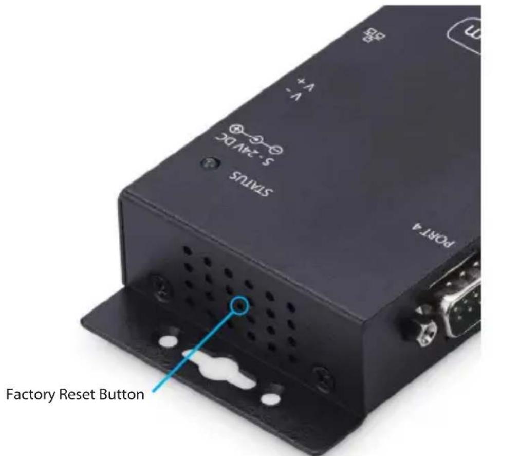
*143-SERIAL-ETHERNET shown
To view manuals, videos, drivers, downloads, technical drawings, and more visit www.startech.com/support
Warranty Information
This product is backed by a two-year warranty.
For further information on product warranty terms and conditions, please refer to www.startech.com/warranty.
Limitation of Liability
In no event shall the liability of StarTech.com Ltd. and StarTech.com USA LLP (or their officers, directors, employees or agents) for any damages (whether direct or indirect, special, punitive, incidental, consequential, or otherwise), loss of profits, loss of business, or any pecuniary loss, arising out of or related to the use of the product exceed the actual price paid for the product.
Some states do not allow the exclusion or limitation of incidental or consequential damages. If such laws apply, the limitations or exclusions contained in this statement may not apply to you.
Hard-to-find made easy. At StarTech.com, that isn't a slogan. It's a promise.
StarTech.com is your one-stop source for every connectivity part you need. From the latest technology to legacy products — and all the parts that bridge the old and new — we can help you find the parts that connect your solutions.
We make it easy to locate the parts, and we quickly deliver them wherever they need to go. Just talk to one of our tech advisors or visit our website. You'll be connected to the products you need in no time.
Visit www.StarTech.com for complete information on all StarTech.com products and to access exclusive resources and time-saving tools.
StarTech.com is an ISO 9001 Registered manufacturer of connectivity and technology parts. StarTech.com was founded in 1985 and has operations in the United States, Canada, the United Kingdom and Taiwan servicing a worldwide market.
Reviews
Share your experiences using StarTech.com products, including product applications and setup, what you love about the products, and areas for improvement.
StarTech.com Ltd.
45 Artisans Crescent
London, Ontario
N5V 5E9
Canada
StarTech.com LLP
4490 South Hamilton Road
Groveport, Ohio
43125
U.S.A.
StarTech.com Ltd.
Unit B, Pinnacle 15
Gowerton Road Brackmills,
Northampton
NN4 7BW
United Kingdom
StarTech.com Ltd.
Siriusdreef 17-27
2132 WT Hoofddorp
The Netherlands
FR: fr.startech.com
DE: de.startech.com
ES: es.startech.com
NL: nl.startech.com
IT: it.startech.com
JP: jp.startech.com


- RS232 Serial Over IP Device Server
- User Manual
- Compliance Statements
- FCC Compliance Statement
- Industry Canada Statement
- Use of Trademarks, Registered Trademarks, and other Protected Names and Symbols
- Safety Statements
- Safety Measures
- Mesures de sécurité
- Table of Contents
- Product Diagram (I23-SERIAL-ETHERNET)
- Rear View
- Product Diagram (I43-SERIAL-ETHERNET)
- Product Information
- Package Contents
- Installation
- Default Settings
- Out of the Box Settings
- Factory Default Button Settings
- Hardware Installation
- (Optional) Configure DB-9 Pin 9 Power
- (Optional) Mounting The Serial Device Server With DIN Rail
- (Optional) Mounting The Serial Device Server To A Wall Or Other Surface
- Install the Serial Device Server
- Software Installation
- Operation
- Telnet
- Use the Software to Discover the Serial Device Server
- Configure the Serial Port Settings
- Available Serial Port Options
- In the Software
- In the Web Interface
- Changing COM Port or Baud Rate in Windows
- LED Chart
- Factory Reset Procedure
- Warranty Information
- Limitation of Liability
- Hard-to-find made easy. At StarTech.com, that isn't a slogan. It's a promise.
- Reviews
- StarTech.com Ltd.
- StarTech.com LLP
Brand : StarTech.com
Model : I43-SERIAL-ETHERNET
Category : AV Accessory