IOD200 - Ice Maker Scotsman - Free user manual and instructions
Find the device manual for free IOD200 Scotsman in PDF.

User questions about IOD200 Scotsman
0 question about this device. Answer the ones you know or ask your own.
Ask a new question about this device
Download the instructions for your Ice Maker in PDF format for free! Find your manual IOD200 - Scotsman and take your electronic device back in hand. On this page are published all the documents necessary for the use of your device. IOD200 by Scotsman.
USER MANUAL IOD200 Scotsman
IOD Series Water/Ice Dispensers
Installation, Operation and Maintenance Manual
Original Instructions — This manual is updated as new information and models are released. Visit our website for the latest manual. www.scotsman-ice.com
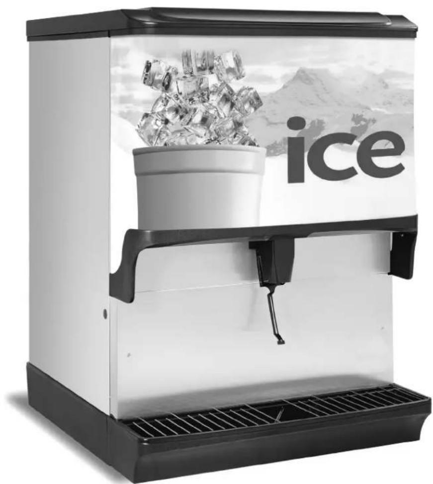
natural_image
Black and white photo of a modern ice creamer with a bucket and ice cubes, set against a snowy mountain backdrop (no text or symbols visible)Safety Notices
As you work on Scotsman Ice equipment, be sure to pay close attention to the safety notices in this manual. Disregarding the notices may lead to serious injury and/or damage to the equipment.
Throughout this manual, you will see the following types of safety notices:
▲Warning
Text in a Warning box alerts you to a potential personal injury situation. Be sure to read the Warning statement before proceeding, and work carefully.
!Caution
Text in a Caution box alerts you to a situation in which you could damage the equipment. Be sure to read the Caution statement before proceeding, and work carefully.
Procedural Notices
As you work on Scotsman Ice equipment, be sure to read the procedural notices in this manual. These notices supply helpful information which may assist you as you work.
Throughout this manual, you will see the following types of procedural notices:
Important
Text in an Important box provides you with information that may help you perform a procedure more efficiently. Disregarding this information will not cause damage or injury, but it may slow you down as you work.
NOTE: Text set off as a Note provides you with simple, but useful, extra information about the procedure you are performing.
Read These Before Proceeding
▲Warning
PERSONAL INJURY POTENTIAL
Do not operate equipment that has been misused, abused, neglected, damaged, or altered/modified from that of original manufactured specifications.
▲Warning
The installer is responsible to provide a suitable plug meeting all requirements, or a means for disconnection must be incorporated in the wiring according to the wiring rules.
▲Warning
This appliance is intended to be used indoors in kitchens or back rooms of food/restaurant establishments.
▲Warning
This appliance is not intended for use by persons (including children) with reduced physical, sensory or mental capabilities, or lack of experience and knowledge, unless they have been given supervision concerning use of the appliance by a person responsible for their safety. Do not allow children to play with this appliance.
Caution
Proper installation, care and maintenance are essential for maximum performance and trouble-free operation of your Scotsman Ice equipment. Read and understand this manual. It contains valuable care and maintenance information. If you encounter problems not covered by this manual, do not proceed, contact Scotsman Ice Foodservice Group.
Important
Routine adjustments and maintenance procedures outlined in this manual are not covered by the warranty.
Table of Contents
Section 1 General Information
Read This Manual ....5
Unit Inspection 5
Serial Number Location 5
Warranty Information 5
Model Numbers......5
How to Read a Model Number....5
Accessories....6
Legs 6
Manual Fill Lid 6
Ice Flow Restrictor....6
Section 2 Installation
General....7
Dimensions 7
Max Noise dB(A) 7
Footprints 8
Location 9
Ways Equipment Should Not be Used 9
Location Requirements for Top Mounted Ice Machine Installations....9
Electrical....10
General....10
Minimum Circuit Ampacity....10
Electrical Requirements 10
Voltage 10
Minimum Circuit Amperage Chart....10
Grounding Instructions....10
Pump Deck Wiring 11
Water Supply 12
Recommended Plumbing 12
Drains 12
Step by Step Installation....13
General....13
Specifications Chart....13
Unit Installation....13
Starting Your WATER/ICE Dispenser....14
Section 3 Operation
Component Identification 15
Sequence of Operation 15
Ice Recommended for Dispensing....15
Ice Storage and Dispensing....15
Rocking Chute Ice Dispensing....15
Agitation Timer....16
Operation Checks and Adjustments 16
Rocking Chute Ice Delivery Switch Adjustment.... 16
Section 4 Maintenance
Cleaning & Sanitizing....17
General....17
Daily Cleaning....17
Cleaning Checklist 18
Preventative Maintenance 19
Disassembly....19
Disassembly for Cleaning & Maintenance....19
Disassemble the Rocking Chute 20
Non-front Serviceable Gear Motor Removal 20
Front Serviceable Gear Motor Removal 22
Shipping, Storage and Relocation 22
Section 5 Troubleshooting
Checklist....23
Section 1 General Information
Read This Manual
Scotsman Ice developed this manual as a reference guide for the owner/operator and installer of this equipment. Please read this manual before installation or operation of the machine. A qualified service technician must perform installation and start-up of this equipment, consult Section 5 within this manual for service assistance.
If you cannot correct the service problem, call your Scotsman Service Agent or Distributor. Always have your model and serial number available when you call.
Your Service Agent ____
Service Agent Telephone Number ____
Your Local Distributor
Distributor Telephone Number ____
Model Number ____
Serial Number ____
Installation Date ____
Unit Inspection
Thoroughly inspect the unit upon delivery. Immediately report any damage that occurred during transportation to the delivery carrier. Request a written inspection report from a claims inspector to document any necessary claim.
Serial Number Location
This number is required when requesting information from your local distributor. The serial number is listed on the SERIAL NUMBER DECAL affixed to the dispenser.
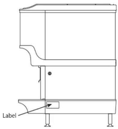
text_image
LabelSerial Number Location
Warranty Information
Visit www.scotsman-ice.com for:
- Warranty Verification
- Warranty Registration
• View and download a copy of your warranty
Model Numbers
This manual covers the following models:
Beverage/Ice Dispensers
IOD150, IOD200, IOD250
HOW TO READ A MODEL NUMBER

flowchart
graph TD
    A["Model Prefix"] --> B["IOD250-1A"]
    C["Ice Capacity"] --> B
    B --> D["IOD - Ice Only Dispenser"]
Accessories
LEGS
Legs are optional equipment with most dispensers.
Standard legs are 4" (10.2 cm) tall stainless steel legs. If an ice machine is installed on top of the dispenser, legs must not be installed. We do not recommend using legs when an ice machine is mounted on the dispenser. The combined weight of the dispenser, ice and ice machine is more evenly distributed when the base area of the dispenser is in contact with the countertop.
MANUAL FILL LID
If you are top mounting your dispenser with an ice machine, you will require a lid for the manual fill area at the top, front of the dispenser.
If you ordered a dispenser and an ice machine at the same time, the manual fill lid was included with the unit. The manual fill lid can be ordered from your local distributor.
ICE FLOW RESTRICTOR
An optional ice flow restrictor decreases the amount of ice allowed to enter the ice chute by blocking a small area at the entrance of the dispenser chute. This in turn restricts the flow of ice that is dispensed into your cup.
Please refer to the instructions included in kit #5013822 for more information on how to install.

natural_image
Metallic tray with two screws, no visible text or symbolsIce Flow Restrictor
Section 2 Installation
General
These instructions are provided to assist the qualified installer. Contact your Scotsman Service Agent or call Scotsman for information regarding start-up services.
The unit should be installed and serviced by a suitably trained person.
Important
Failure to follow these installation guidelines may affect warranty coverage.
Dimensions
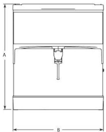
text_image
A B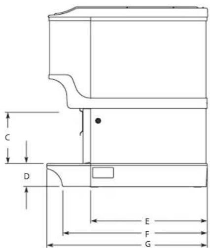
text_image
C D E F G
text_image
H l| Model/Ice Capacity | A B C D E F G H I | ||||||||
| IOD150-1A | 34.81"(88.4 cm) | 23.00"(58.4 cm) | 9.94"(17.6 cm) | 4.44"(11.3 cm) | 22.63"(57.5 cm) | 28.00"(71.1 cm) | 31.13"(79.1 cm) | 20.00"(50.8 cm) | 20.44"(51.9 cm) |
| IOD200-1A | 34.81"(88.4 cm) | 30.00"(76.2 cm) | 9.94"(17.6 cm) | 4.44"(11.3 cm) | 22.63"(57.5 cm) | 28.00"(71.1 cm) | 31.13"(79.1 cm) | 20.00"(50.8 cm) | 27.44"(69.7 cm) |
| IOD250-1A | 39.81"(101.1 cm) | 30.00"(76.2 cm) | 9.94"(17.6 cm) | 4.44"(11.3 cm) | 22.63"(57.5 cm) | 28.00"(71.1 cm) | 31.13"(79.1 cm) | 20.00"(50.8 cm) | 27.44"(6 9 . 7 cm) |
Max Noise dB(A)
Noise emission from all models does not exceed 70 dB(A).
Footprints
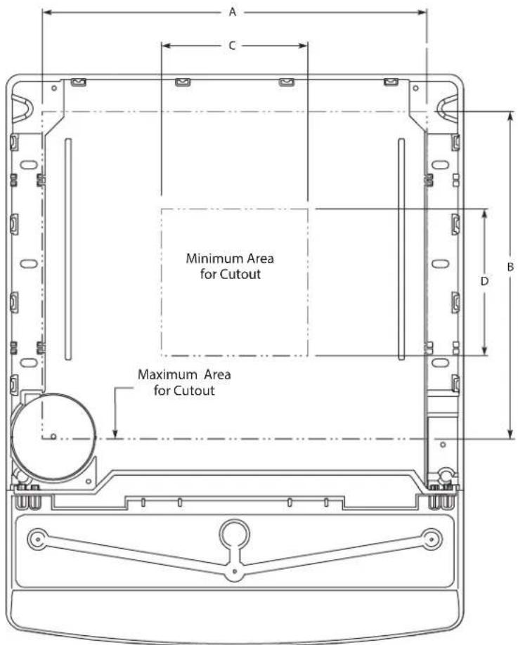
text_image
A C Minimum Area for Cutout Maximum Area for Cutout B DNOTE: Footprint for IOD shown.
| IOD | Maximum Minimum | |||
| A B C D | ||||
| 150 | 19.00"(48.3 cm) | 17.81"(45.2 cm) | 8.00"(20.3 cm) | 8.00"(20.3 cm) |
| 200 | 26.00"(66.0 cm) | 17.81"(45.2 cm) | 8.00"(20.3 cm) | 8.00"(20.3 cm) |
| 250* | 26.00"(66.0 cm) | 17.81"(45.2 cm) | 8.00"(20.3 cm) | 8.00"(20.3 cm) |
▲Warning
Cutting the counter top may decrease its strength. Counter must be braced to support the dispenser counter top weight plus ice storage capacity and weight of ice machine, if applicable.
Location
The location selected for the beverage dispenser must meet the following criteria. If any of these criteria are not met, select another location.
- Dispenser is only to be installed in locations where it can be overseen by trained personnel.
- The air temperature must be at least 50^ (10°C), but must not exceed 95^ (35°C).
- The location must not be near heat-generating equipment or in direct sunlight and must be protected from weather.
- The counter top must be level. Verify that the counter top can support the weight of the dispenser, or the dispenser/ice machine combination plus the weight of the stored ice.
- Water lines, drains and power outlet must be within 6' (1.8 m) of location.
Ways Equipment Should Not be Used
This equipment should be used only in accordance with the instructions. This equipment is designed to be installed on a counter, dispense ice, and/or carbonate, chill mains potable water, and chill soft drink syrup. It should not be used for any other purpose.
- Do not use the product coils to chill other products than those stated above.
- Do not operate the equipment in a wet environment. Any spillage must be wiped dry immediately.
- The unit should not be installed in small enclosed spaces such as cupboards or pantries, where fresh air flow is restricted and service may not be able to access.
- Keep the unit free from excessive heat and cold.
- Misuse or use of the equipment for any other purpose than those identified above will invalidate any warranty and may constitute a danger to yourself and others.
Location Requirements for Top Mounted Ice Machine Installations
Location — Avoid placing the dispenser and/or ice machine near heat sources such as radiators, ovens, refrigeration equipment and direct sunlight.
Clearances — Refer to the ice machine installation manual for clearances.
Front of ice machine to be flush with front of dispenser — Some ice machines may overhang at the back of the dispenser.
Drains — A separate drain line is required for the ice machine, in addition to a drain line for the ice/beverage dispenser.
Dispensers may require an adapter kit to install some top-mounted ice machines. Contact your local distributor for the correct adapter kit.
For full information about ice machine installation, including clearances, plumbing lines, connections, and electrical requirements, see the ice machine installation manual.
Electrical
GENERAL
▲Warning
All wiring must conform to local, state and national codes. Changes to the mains cable and plug can only be made by a qualified electrician.
MINIMUM CIRCUIT AMPACITY
The minimum circuit ampacity is used to help select the wire size of the electrical supply. (Minimum circuit ampacity is not the beverage/ice machine's running amp load.) The wire size (or gauge) is also dependent upon location, materials used, length of run, etc., so it must be determined by a qualified electrician.
ELECTRICAL REQUIREMENTS
Refer to Ice Machine Model/Serial Plate for voltage/amperage specifications.
VOLTAGE
The standard voltage for IOD Series dispensers is 120VAC-60Hz. A power cord is provided with 120VAC-60Hz models only. IOD Series dispensers use a 1/7 hp gearmotor.
MINIMUM CIRCUIT AMPERAGE CHART
Important
Due to continuous improvements, this information is for reference only. Please refer to the dispenser serial number tag to verify electrical data. Serial tag information overrides information listed on this page.
| Dispenser Voltage/Cycle | Minimum Circuit Amps | |
| IOD150, IOD200, IOD250, | 115/60 2.8 | |
GROUNDING INSTRUCTIONS
▲Warning
The beverage/ice machine must be grounded in accordance with national and local electrical codes.
This appliance must be grounded. In the event of malfunction or breakdown, grounding provides a path of least resistance for electric current to reduce the risk of electric shock. This appliance is equipped with a cord having an equipment-grounding conductor and a grounding plug. The plug must be plugged into an appropriate outlet that is properly installed and grounded in accordance with all local codes and ordinances.
▲Warning
Improper connection of the equipment-grounding conductor can result in a risk of electric shock. The conductor with insulation having an outer surface that is green with or without yellow stripes is the equipment grounding conductor. If repair or replacement of the cord or plug is necessary, do not connect the equipment-grounding conductor to a live terminal. Check with a qualified electrician or serviceman if the grounding instructions are not completely understood, or if in doubt as to whether the appliance is properly grounded. Do not modify the plug provided with the appliance — if it will not fit the outlet, have a proper outlet installed by a qualified electrician.
▲Warning
When using electric appliances, basic precautions must always be followed, including the following:
a. Read all the instructions before using the appliance.
b. To reduce the risk of injury, close supervision is necessary when an appliance is used near children.
c. Do not contact moving parts.
d. Only use attachments recommended or sold by the manufacturer.
e. Do not use outdoors.
f. For a cord-connected appliance, the following shall be included:
- Do not unplug by pulling on cord. To unplug, grasp the plug, not the cord.
- Unplug from outlet when not in use and before servicing or cleaning.
- Do not operate any appliance with a damaged cord or plug, or after the appliance malfunctions or is dropped or damaged in any manner. Contact the nearest authorized service facility for examination, repair, or electrical or mechanical adjustment.
g. For a permanently connected appliance — Turn the power switch to the off position when the appliance is not in use and before servicing or cleaning.
h. For an appliance with a replaceable lamp — Always unplug before replacing the lamp. Replace the bulb with the same type.
i. For a grounded appliance — Connect to a properly grounded outlet only. See Grounding Instructions.
PUMP DECK WIRING
The supply cord is equipped with a three-prong 5-15P. When a Ground Fault Circuit Interrupter (GFCI) is required by code, a breaker type protector must be used. We do not recommend GFIC outlets as they are known for more intermittent nuisance trips than panel breakers. To ensure both the safety and proper operation of this equipment, be certain that the electrical receptacle is a proper design so as to accept this plug, ensuring that the carbonator assembly is properly grounded.
If the pump deck is to be installed in an area or community whose local codes require permanent wiring, the following procedure must be followed.
- The three wires (white, black and green) must be fed through the cable connector and brought into the wiring compartment. The cable must be secured into the connector.
- The green wire from the cable must be connected to the green screw that attaches to the inside panel of the wiring compartment. Be sure to use a ring torque terminal for connecting the wire to the screw.
- The white wire from the cable must be joined to the N terminal of the liquid level control board by a suitable U.L. listed insulated cable connector.
- The black wire from the cable must be joined to the L1 terminal of the liquid level control board by a suitable U.L. listed insulated cable connector.
Water Supply
RECOMMENDED PLUMBING
All plumbing must conform to local, state, and national codes. Scotsman Ice recommends that a double non-return valve is fitted before the unit on installation. The unit is not connected to the water mains by a factory supplied hose set and it is up to the installer to fit an appropriate food grade hose, rated to a minimum operating pressure of 145 psi (10 bar, 1000000 Pa). All connections should be made using a permanent retaining method e.g. Oetiker clip.
The plumbing diagram is printed on a white vinyl label, located above the inlet tubes for syrup and water. The plumbing diagram label can be accessed by removing the splash panel of the dispenser. The plumbing diagram label explains which inlet coldplate fittings supply which dispenser valves and water manifolds.
The water supply must first be connected to the carbonator pump (not shown) before plumbing to connection "A" shown on plumbing diagram. The carbonator pump deck must be within 6' (1.8 m) of the dispenser for optimum performance. See BIB installation diagram for system pressure settings.
Diagram Locations
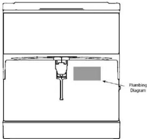
text_image
Plumbing DiagramDrains
IOD Series dispensers drain through a double connection to the drain pan.
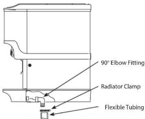
text_image
90° Elbow Fitting Radiator Clamp Flexible Tubing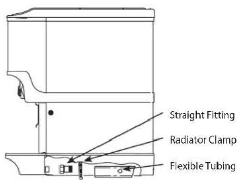
text_image
Straight Fitting Radiator Clamp Flexible Tubing
text_image
Rear Access for Drain Hose and Beverage LinesDrainage Through Bottom Drainage Through Back Rear View
Step by Step Installation
GENERAL
IOD Series dispensers have a stainless steel cabinet and lighted merchandiser standard.
Beverage valves, cold plate connections, drain connections and electrical components are front serviceable.
SPECIFICATIONS CHART
| Min. Max | ||
| Water pressure (Incoming from Water Main) | 40 psi(2.76 BAR 275,790 Pa) | 55 psi(3.79 BAR 379,211 Pa) |
| Ambient temperature 40°F | (4°C) 105°F (41°C) |
* This is the optimal pressure. When the foam is too high, decrease the pressure; when spitting/popping is an issue, increase the pressure.
UNIT INSTALLATION
- Place the dispenser in the desired location.
- Run the beverage lines and water lines; make sure to install the water connections to the proper inlets. Connection "A" comes from the brass carbonator pump and connection "B" is your plain water supply.
Install Plumbing Drains & Insulate
- Connect Drain Kit to drain pan (see Drains on page 12).
- Extended splash panel units do the following:
A. Remove the extended splash panel from the unit by removing the two (2) Phillips head screws holding it in place.
B. Determine drain setup and screw either the 90° or straight line drain fittings into the collector box included with the drain kit (see Drains on page 12).

text_image
Straight Fittings 90° Fittings Collector Box Drain Line FittingsNOTE: Depending on the drain setup, connect the straight fittings to the collector box if the drain lines are to run straight back underneath the unit or the 90^ fittings if the drain lines run down through the countertop.
C. Using the provided radiator clamps connect and secure the drain lines to the collector box fittings with a standard screwdriver or 5/16 nut driver.

text_image
Drain Line Drain Line Fitting Collector BoxD. Mount the collector box to the bracket by sliding the right and left bracket tabs into the slots on the collector box.
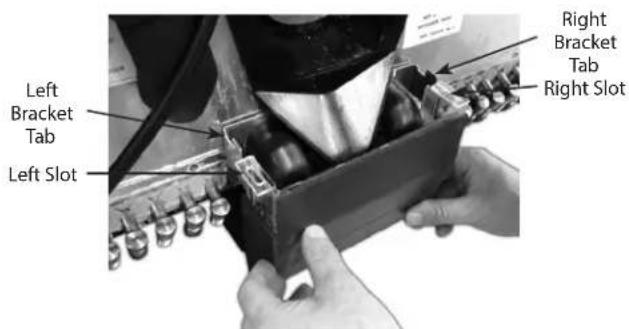
text_image
Left Bracket Tab Left Slot Right Bracket Tab Right SlotE. Be sure the 90^ rubber ice bin drain elbows are routed into the collector box.

text_image
90° Elbow Left Tab In Slot 90° Elbow Right Tab In SlotF. Reinstall the extended splash panel.
- Fill bin with ice.
Important
If incoming water pressure is under 40 psi (2.76 BAR, 275,790 Pa), a water booster is recommended. If incoming water pressure is over 55 psi (3.79 BAR 379, 211 Pa), a water regulating valve is required.
STARTING YOUR WATER/ICE DISPENSER
Upon completion of the beverage dispenser and/or system installation, all tubing, dispenser, and system components must be cleaned and sanitized prior to use.
NOTE: At installation, equipment, dispensers, and tubing get moved through many environments, dirt, dust, chases, insulation, drywall, etc. It is an important procedure and best practice to address cleaning to deliver the best quality drink to your customer.
Important
Clean and sanitize the water and syrup circuits according to instructions provided in this manual. Clean and sanitize the dispenser components according to instructions provided in this manual. Seal to counter top when no legs are used with the unit. Consult and use local health codes if a discrepancy occurs between this manual and your local health codes.
Section 3
Operation
Component Identification
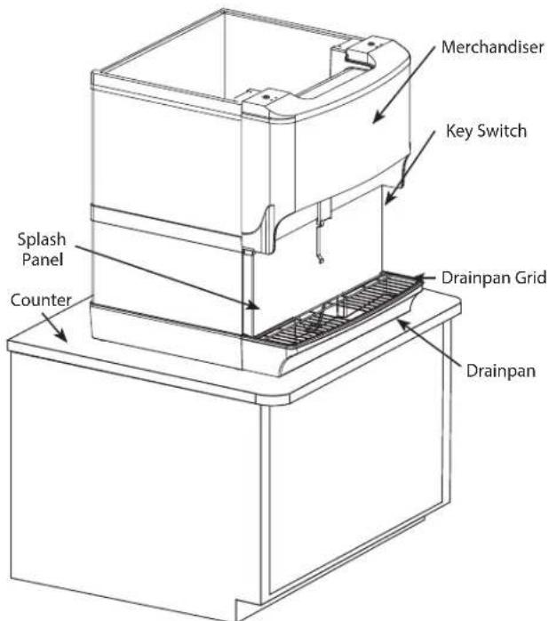
text_image
Merchandiser Key Switch Splash Panel Counter Drainpan Grid DrainpanSequence of Operation
ICE RECOMMENDED FOR DISPENSING
Dispensers are designed to dispense hard, cube ice up to one-inch square. The ice shapes and sizes listed below are recommended for dispensing.
Warm "Super Cooled" Ice Before Dispensing: "Super Cooled" ice is not recommended for dispensing. "Super cooled" ice is ice that has been stored in freezers below 32°F. If it is necessary to temporarily use "super cooled" ice, allow the ice to warm at room temperature for 25 to 30 minutes before placing the ice in the dispenser.
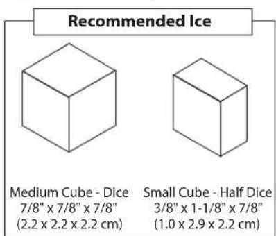
text_image
Recommended Ice Medium Cube - Dice 7/8" x 7/8" x 7/8" (2.2 x 2.2 x 2.2 cm) Small Cube - Half Dice 3/8" x 1-1/8" x 7/8" (1.0 x 2.9 x 2.2 cm)ICE STORAGE AND DISPENSING
As the customer presses the rocking chute, the arm at the top left rear of the chute pushes upward on the door lock. The door opens until it contacts the stops in the mounting brackets. The plastic arm on the ice chute also activates the lever of the ice dispensing switch. When activated, the micro switch starts the gear motor. The gear motor turns the paddle wheel and agitator arm.
The paddlewheel carries ice. Periodic agitation is standard on the 30" and larger dispensers. During periodic agitation, the paddle wheel and agitator turn for approximately three seconds every three and one half-hours. The door lock prevents ice from being dispensed during the agitation cycle.
ROCKING CHUTE ICE DISPENSING
As the customer presses the rocking chute, the arm at the top left rear of the chute pushes upward on the door lock. The door opens until it contacts the stops in the mounting brackets. The plastic arm on the ice chute also activates the lever of the ice dispensing switch. When activated, the micro switch starts the gear motor. The gear motor turns the paddle wheel and agitator bar.
AGITATION TIMER
The timer is non-adjustable and is set to agitate the ice for 3 seconds every 3.5 hours. Activating the dispenser will reset the timer. After 3.5 hours of non-use, the timer will energize the dispenser motor.
The LED tells the technician in which mode the timer is operating. Rather than a jumper pin, this timer has a female spade connector that must be connected to terminal number 6.
When this jumper is in place, the LED will blink at one-second intervals. This is the run mode.
When the jumper is open, the LED will flash every 0.4 second. This is the test mode and the timer will cycle every 55 seconds in test mode. If the timer is left in test mode, it will automatically reset to run mode.

text_image
1 COM 5 NC 4 NO RED 3 2 6Agitation Timer
Operation Checks and Adjustments
ROCKING CHUTE ICE DELIVERY SWITCH ADJUSTMENT
To properly adjust the switch, first unplug the power cord to the unit, then remove the merchandiser. This will give you access to the ice delivery switch located on the left side of the rocking chute.
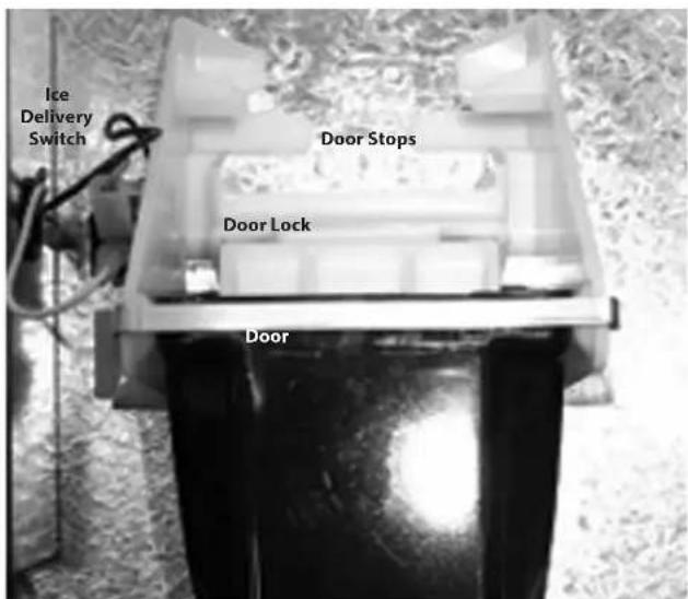
text_image
Ice Delivery Switch Door Stops Door Lock DoorBegin by observing the chute by slowly pushing against the rocking chute. When the ice delivery switch clicks, measure the distance from the door stops on the rocking chute bracket to the door. The distance between the two must be no more than 1/4" (0.64 cm), but no less than 1/16" (0.16 cm).

text_image
Door Stops Door Door Lock 1/16" to 1/4"The left side of the rocking chute has a tab that pushes up on the ice delivery switch. To adjust it, use needle nose pliers and bend the arm of the switch up or down in order to change the point where the tab makes contact with the switch arm.

text_image
Switch Arm TabSection 4 Maintenance
Cleaning & Sanitizing
GENERAL
You are responsible for maintaining the dispenser in accordance with the instructions in this manual. Maintenance procedures are not covered by the warranty.
Clean and sanitize the dispenser every six months for efficient operation. An extremely dirty dispenser may require more frequent cleaning and sanitizing due to operating environment and/or water quality. If the dispenser requires more frequent cleaning and sanitizing, consult a qualified service company to test the water quality and recommend appropriate water treatment.
▲Warning
Never use a high-pressure water jet for cleaning or hose down or flood interior or exterior of units with water. Do not use power cleaning equipment, steel wool, scrapers or wire brushes on stainless steel or painted surfaces.
DAILY CLEANING
All cleaning must meet your local health department regulations. The following cleaning instructions are provided as a guide.
Caution
Use only warm soapy water to clean the exterior of the tower. Do not use solvents or other cleaning agents. Do not pour hot coffee into the drain pan. Pouring hot coffee down the drain pan can eventually crack the drain pan, especially if the drain pan is cold or still contains ice.
▲Warning
This Electric Shock Hazard
Unplug unit before servicing or cleaning.
▲Warning
When using cleaning fluids or chemicals, rubber gloves and eye protection must be worn.
Clean the exterior and drain pan:
- Lift the grid and remove it from the drain pan.
- Using mild soap, warm water and a clean cloth, wipe the drain pan and splash panel. Then, rinse with clean, warm water. Allow plenty of warm (not hot) water to run down the drain of the drain pan, to remove syrup residue that can clog the drain opening.
- Wash the grid, then rinse with clean water. Place the grid back in the drain pan.
- Wash all exterior surfaces of the unit with warm water and a clean cloth. Wipe again with a clean, dry cloth.
Cleaning/Sanitizing Procedure
This procedure must be performed a minimum of once every six months.
- The dispenser and bin must be disassembled, cleaned and sanitized (See Disassembly in this section).
- All ice produced during the cleaning and sanitizing procedures must be discarded.
- Removes mineral deposits from areas or surfaces that are in direct contact with water.
▲Warning
Unplug unit before servicing or cleaning ice bin.
Ice bin contains parts that can move at any time and will cause injury if hands are in the way.
⚠ Warning
When using cleaning fluids or chemicals, rubber gloves and eye protection must be worn.
Clean and sanitize the ice bin:
- Unplug unit and remove all ice from the ice bin.
- Mix a solution of mild detergent to clean the dispenser bin and components.
- Wash the ice bin using a sponge and the mild detergent solution.
- Using the mild detergent solution and a soft bristle brush or clean cloth, clean the following dispenser parts:
- Entire bin
- Paddle wheel
- Paddle wheel area
- Agitator
- Paddle wheel pin
- Ice chute
- Rear bushing
- Motor shaft
-
Strip lids (where applicable)
-
Rinse all the parts in clean, running water.
-
Prepare approximately 2 gallons (7.6 liters) of sanitizing solution by mixing 1/2 ounce (15 ml) of household bleach (that contains 5.25% sodium hypochlorite) with 2 gallons (7.6 liters) of 120°F water. The mixture must not exceed 100 PPM of chlorine. Or mix a solution of any approved sanitizer, following the directions for mixing and applying the sanitizer.
-
Sanitize the ice bin and cold plate with the sanitizing solution for at least 10 seconds.
-
Allow to air dry. Do not rinse.
Re-assembling the dispenser parts:
-
Re-assemble parts in the following order:
-
Bin liner
- Paddle wheel
- Agitator
- Paddle wheel pin
- Ice chute
-
Merchandiser
-
Hand tighten all knurled fasteners.
-
Pour in fresh, sanitary ice and replace the plastic lid on the top of the dispenser.
-
Plug in the unit's electrical cord.
-
Check for proper ice dispensing.
CLEANING CHECKLIST
- Clean drain pan, grid, and splash panel.
- Clean the valve nozzles and diffusers.
Preventative Maintenance
Preventative maintenance is a vital part of keeping your dispenser in top condition. Following the guidelines below will assist you in continued trouble-free operation of your unit.
- Conduct daily maintenance of the machine.
- Perform monthly maintenance of the machine.
- Perform periodic maintenance and sanitizing of beverage system.
- Do not overfill the dispenser bin with ice.
- Do not allow the dispenser to sit for prolonged periods of non-use with ice in the bin.
- Most ice dispenser service problems are caused by low usage of the ice dispenser.
- Do not allow ice to remain in the bin more than a day in order to prevent ice from freezing together and/or stagnant ice.
Possible excess ice storage reasons:
• Storage capacity exceeds daily requirements.
- Low demand during the off-season.
- Dispenser oversized with future growth in mind.
Lower ice storage to meet one day's needs. If you manually fill ice, fill only with the appropriate amount of ice. Fill the dispenser with fresh ice each morning. Do not fill the dispenser at night just before shut down. Ice cubes can freeze together if not dispensed.
Disassembly
DISASSEMBLY FOR CLEANING & MAINTENANCE
NOTE: Sanitize the ice dispenser at Initial Start-up in addition to monthly sanitizing. You will need a slotted screwdriver in order to disassemble.
Disassemble parts in the following order:
A. Merchandiser
B. Ice chute
C. Paddle wheel or agitator pins
D. Agitator
E. Paddle wheel
F. Bin liner
G. Paddle wheel area
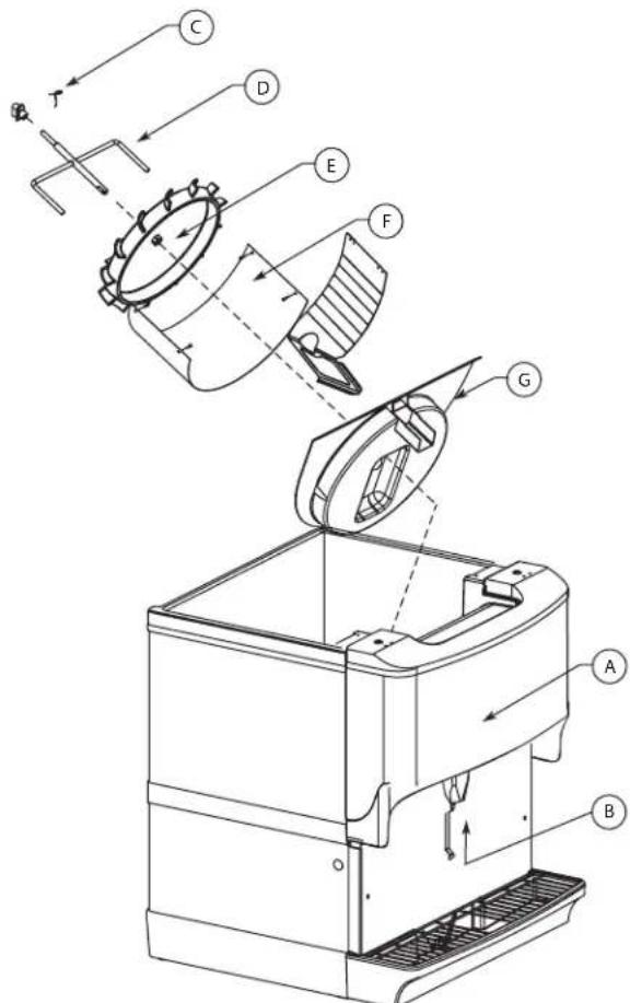
text_image
Technical diagram of a mechanical device with labeled components (A, B, C, D, E, F, G) and directional arrows indicating flow or movement.Beverage/Ice Dispenser
Accessing a Dispenser Bin Top Mounted with a Scotsman Ice Machine:
- Remove the front panel of the ice machine.
- Remove the ice deflection baffle. This will give you access to the dispenser bin.
- If the Scotsman Ice machine is operating, wait for the sheet of ice to fall into the dispenser bin, then place toggle switch of the ice machine to the OFF position. If the ice machine is NOT operating, place the toggle switch of the ice machine to the OFF position right away.
- On models without a top mounted ice machine, remove the plastic lid from the top of the dispenser.
- Remove all ice from the dispenser.
-
Disconnect electrical power to the dispenser.
-
Remove agitator arm and paddlewheel pin.
Non-front Serviceable Motor
a. Rotate the agitator arm so the paddle wheel pin handle is pointing up, toward the ceiling.
b. Prepare agitator pin for removal by removing the stainless steel split ring.
c. Then remove the paddle wheel pin from the hole in the agitator.
d. Push the agitator bar toward the back of the unit until the agitator is free of the paddle wheel hub.
Front Serviceable Motor
a. With agitator arm in any position remove hitch clip pin from the mushroom bushing on the rear of the ice bin.
b. Push the agitator bar toward the bushing to remove it from the paddle wheel hub.
NOTE: If a top mount ice machine is installed, sliding the ice machine to one side will make bin component removal easier. If the ice machine is hard plumbed it will need to be disconnected.
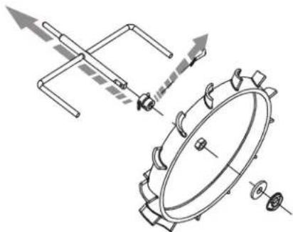
natural_image
Technical line drawing of a mechanical assembly with no visible text or symbolsNon-front Serviceable
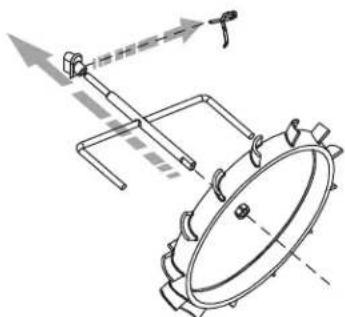
natural_image
Technical line drawing of a mechanical assembly with gears and linkages (no text or symbols)Front Serviceable
- Remove paddle wheel, bin liner and paddle wheel area.
- Move the front of the agitator to one side and slide the agitator forward until the rear of the agitator shaft is clear of the bushing.
- Remove the agitator from the bin area.
- Slide the paddle wheel from its shaft.
- Loosen the four knurled fasteners that hold the bin liner in place.
- Remove the bin liner.
- Remove the paddle wheel area from the bin.
- Discard the remaining ice in the bin.
DISASSEMBLE THE ROCKING CHUTE
NOTE: For all Quickdraw units, refer to Quickdraw Components in this section for ice chute information.
- Loosen the two knurled fasteners that hold the merchandiser in place.
- Remove the merchandiser.
- Remove outer bracket.
- Remove door lock.
- Remove door.
- Remove ice chute.
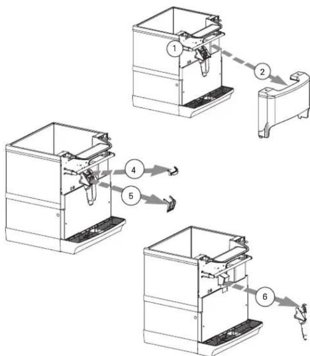
flowchart
graph TD
    A["Component 1"] --> B["Component 2"]
    B --> C["Component 3"]
    C --> D["Component 4"]
    D --> E["Component 5"]
    E --> F["Component 6"]
Ice Chute Removal
NON-FRONT SERVICEABLE GEAR MOTOR REMOVAL
These instructions are provided as a guide for the removal of the gear motor. Depending on the model number of your dispenser, these instructions may vary slightly.
- Disconnect power from the electric receptacle.
- Remove all ice from the ice storage bin of the dispenser.
-
Remove the paddle wheel pin from the paddle wheel agitator assembly inside the dispenser bin.
-
Remove the agitator assembly from the dispenser bin by pushing the agitator to the back of the bin. Angle the front of the agitator to the side. Pull the agitator forward then out of the dispenser.
- Remove the paddle wheel from the dispenser by pulling the hub of the paddle wheel to the back of the bin and off the gear motor shaft.
- Remove the splash panel from the dispenser and expose the gear motor.
- Disconnect the electric connector from the gear motor wire leads.
- Remove the pin in front of the gear motor.
- You must be able to remove the gear motor from the dispenser.
- To install a replacement gear motor, reverse this procedure.
text_image
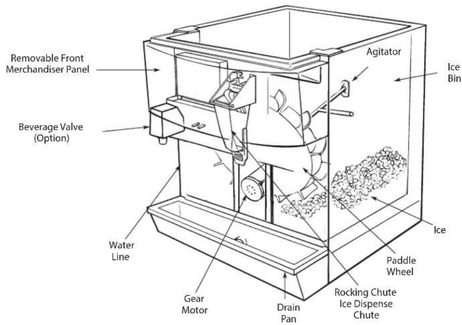
Removable Front Merchandiser Panel Agitator Ice Bin Beverage Valve (Option) Water Line Gear Motor Drain Pan Rocking Chute Ice Dispense Chute Paddle Wheel Ice IceFRONT SERVICEABLE GEAR MOTOR REMOVAL
These instructions are provided as a guide for the removal of the gear motor. Depending on the model number of your dispenser, these instructions may vary slightly.
- Unplug the dispenser.
- Unplug the motor.
- Remove motor mount pins.

text_image
IMPORTANT OPERATING PRESSURES VEGET PROCESSED: 100% VEGET PROCESSED: 200% VEGET PROCESSED: 300% VEGET PROCESSED: 400% VEGET PROCESSED: 500% VEGET PROCESSED: 600% VEGET PROCESSED: 700% VEGET PROCESSED: 800% VEGET PROCESSED: 900% VEGET PROCESSED: 1000%- Slide motor towards you.
- Notice alignment of the chamfered edge of drive shaft.
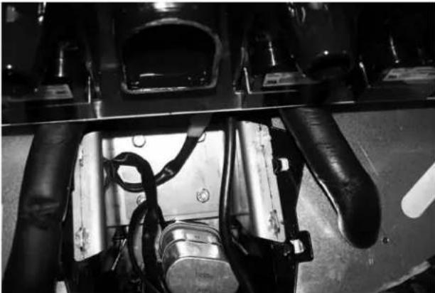
natural_image
Close-up of industrial machinery components with visible wiring and housing (no text or symbols)- New motor must have the same alignment (within 15 degrees).
- To get correct alignment you can do one of two things:
a. Turn drive shaft with an adjustable wrench, being careful not to damage the drive shaft.
b. Plug in the unit, plug in the motor and use the ice dispense switch to move the drive shaft into correct alignment.
-
If you plugged in the unit to help with alignment of drive shaft now unplug the unit.
-
Slide motor up into housing, making sure that the tabs fit on the bracket.
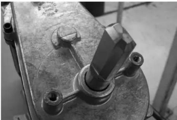
natural_image
Close-up of a mechanical component with a central shaft and bolted joint (no visible text or symbols)- Install motor mount pins.
- Plug in motor.
- Test unit.
Shipping, Storage and Relocation
Caution
Before shipping, storing, or relocating this unit, syrup systems must be sanitized. After sanitizing, all liquids (sanitizing solution and water) must be purged from the unit. A freezing environment causes residual sanitizing solution or water remaining inside the unit to freeze, resulting in damage to internal components.
Section 5
Troubleshooting
Checklist
If a problem arises during operation of your dispenser, follow the checklist below before calling service. Routine adjustments and maintenance procedures are not covered by the warranty.
| Problem Possible | Cause To Correct | |
| Dispenser will not dispense ice (and NO SOUNDS are heard when machine is activated). | No power. Check electrical connection. | |
| Loose wire in electrical system. Thoroughly check all wire connections. | ||
| Dispenser overloaded with ice. Remove ice from dispenser until unit will operate. | ||
| Motor not working. Check thermally protected motor. | Replace motor or capacitor if necessary. | |
| Dispenser will not dispense ice (motor runs but no ice movement is heard in bin). | No ice in bin. Fill dispenser with ice. | |
| Door not opening. Check rocking chute mechanism or electric solenoid operation. | ||
| Paddle wheel pin slipped from the paddle wheel. Replace paddle wheel pin. | ||
| Excessive clustering or bridging of ice. | Loaded ice not broken up. (Caution: Super cooled ice is not covered by the Servend warranty.) | Break ice clusters before manually filling the dispenser. (See ice recommendations.) |
| Excessive water spilling from the ice machine. Adjust ice machine to eliminate water spillage. | ||
| Poorly adjusted ice machine. Adjust ice machine to eliminate large waffle shapes. | ||
| Extremely low usage of the dispenser. Lower the ice level in the bin. | ||
| Ice dispenses continuously. | Misaligned microswitch. Adjust microswitch. | |
| Agitation timer set incorrectly. Test agitation timer. | ||
| Thumping noise or irregular sound at a particular area of the dispenser. | Shaved ice clusters in the bin. | Remove clusters, discover why ice is shaving, and then repair. |
| Dispensing crushed ice or reduced dispensing speed. | Water spillage from ice machine into dispenser bin. | Adjust ice machine. |
| Agitation timer. | Test agitation timer. | |
| Bridge of ice sheet is too thick. | Adjust ice machine. | |
| Paddle wheel area broken or cracked. | Replace paddle wheel area. | |
| Ice clusters in bin. | Break up or remove clusters. | |
| Door not fully open. | Adjust door. | |
| Door will not close. | Ice jammed in chute. | Adjust bridge in ice machine or, when manually filling, break up clusters. |
| Door and/or door lock has come out of place. | Replace door and lock into proper position. | |
| Mounting brackets for rocking chute have spread too far apart. | Bend parts into shape. |
SCOTSMAN ICE SYSTEMS
101 Corporate Woods Parkway
Vernon Hills, IL 60061
www.scotsman-ice.com
800-726-8762