Excellence EW 965 M - Cooker Elba - Free user manual and instructions
Find the device manual for free Excellence EW 965 M Elba in PDF.

User questions about Excellence EW 965 M Elba
0 question about this device. Answer the ones you know or ask your own.
Ask a new question about this device
Download the instructions for your Cooker in PDF format for free! Find your manual Excellence EW 965 M - Elba and take your electronic device back in hand. On this page are published all the documents necessary for the use of your device. Excellence EW 965 M by Elba.
USER MANUAL Excellence EW 965 M Elba
natural_image
Fresh vegetables including garlic, garlic bulbs, and red chili peppers on a white background (no text or symbols)ELBA
TALENT FOR COOKING

natural_image
Close-up of a stainless steel kitchen oven with multiple gas stove fans and heat sinks (no visible text or symbols)
Made in Italy
Dear Customer,
Thank you for having purchased and given your preference to our product.
The safety precautions and recommendations reported below are for your own safety and that of others. They will also provide a means by which to make full use of the features offered by your appliance.
Please preserve this booklet carefully. It may be useful in future, either to yourself or to others in the event that doubts should arise relating to its operation.
This appliance must be used only for the task it has explicitly been designed for, that is for cooking foodstuffs. Any other form of usage is to be considered as inappropriate and therefore dangerous.
The manufacturer declines all responsibility in the event of damage caused by improper, incorrect or illogical use of the appliance.
IMPORTANT SAFETY PRECAUTIONS AND RECOMMENDATIONS
IMPORTANT: This appliance is designed and manufactured solely for the cooking of domestic (household) food and is not suitable for any non domestic application and therefore should not be used in a commercial environment.
The appliance guarantee will be void if the appliance is used within a non domestic environment i.e. a semi commercial, commercial or communal environment.
Read the instructions carefully before installing and using the appliance.
- This appliance has been designed and manufactured in compliance with the applicable standards for the household cooking products and it fulfills all the safety requirements shown in this manual, including those for surface temperatures.
Some people with sensitive skin may have a more pronounced temperature perception with some components although these parts are within the limits allowed by the norms.
The complete safety of the appliance also depends on the correct use, we therefore recommend to always pay a extreme attention while using the product, especially in the presence of children.
- After having unpacked the appliance, check to ensure that it is not damaged and that the oven door closes correctly.
In case of doubt, do not use it and consult your supplier or a professionally qualified technician.
- Packing elements (i.e. plastic bags, polystyrene foam, nails, packing straps, etc.) should not be left around within easy reach of children, as these may cause serious injuries.
- Some appliances are supplied with a protective film on steel and aluminium parts. This film must be removed before using the appliance.
- IMPORTANT: The use of suitable protective clothing/gloves is recommended when handling or cleaning this appliance.
- Do not attempt to modify the technical characteristics of the appliance as this may become dangerous to use. The manufacturer declines all responsibility for any inconvenience resulting from the inobservance of this condition.
- CAUTION: this appliance must only be installed in a permanently ventilated room in compliance with the applicable regulations.
- Do not operate your appliance by means of an external timer or separate remote-control system.
- Do not carry out cleaning or maintenance operations on the appliance without having previously disconnected it from the electric power supply.
- WARNING: Ensure that the appliance is switched off before replacing the oven lamp to avoid the possibility of electric shock.
- Do not use a steam cleaner because the moisture can get into the appliance therefore making it unsafe.
- Do not touch the appliance with wet or damp hands (or feet).
- Do not use the appliance whilst in bare feet.
- If you should decide not to use this appliance any longer (or decide to substitute another model), before disposing of it, it is recommended that it be made inoperative in an appropriate manner in accordance to health and environmental protection regulations, ensuring in particular that all potentially hazardous parts be made harmless, especially in relation to children who could play with unused appliances.
- The various components of the appliance are recyclable. Dispose of them in accordance with the regulations in force in your country. If the appliance is to be scrapped, remove the power cord.
• After use, ensure that the knobs are in the off position.
• Children less than 8 years of age shall be kept away unless continuously supervised.
- This appliance can be used by children aged from 8 years and above and persons with reduced physical, sensory or mental capabilities or lack of experience and knowledge if they have been given supervision or instruction concerning use of the appliance in a safe way and understand the hazards involved.
Children shall not play with the appliance. Cleaning and user maintenance shall not be made by children without supervision.
- The manufacturer declines all liability for injury to persons or damage to property caused by incorrect or improper use of the appliance.
-
WARNING: During use the appliance and its accessible parts become hot; they remain hot for some time after use.
-
Care should be taken to avoid touching heating elements (on the hob and inside the oven).
- The door is hot, use the handle.
-
To avoid burns and scalds, young children should be kept away.
-
Make sure that electrical cables connecting other appliances in the proximity of the cooker cannot come into contact with the hob or become entrapped in the oven door.
- WARNING: Unattended cooking on a hob with fat or oil can be dangerous and may result in fire. NEVER try to extinguish a fire with water, but switch off the appliance and then cover flame e.g. with a lid or a fire blanket.
- WARNING: Danger of fire: do not store items on the cooking surfaces.
- WARNING: When correctly installed, your product meets all safety requirements laid down for this type of product category. However special care should be taken around the rear or the underneath of the appliance as these areas are not designed or intended to be touched and may contain sharp or rough edges, that may cause injury.
- FIRST USE OF THE OVEN - it is advised to follow these instructions:
– Furnish the interior of the oven as described in the chapter "CLEANING AND MAINTENANCE".
- Switch on the empty oven on max to eliminate grease from the heating elements.
- Disconnect the appliance from the electrical power supply, let the oven cool down and clean the interior of the oven with a cloth soaked in water and neutral detergent; then dry carefully.
- CAUTION: Do not use harsh abrasive cleaners or sharp metal scrapers to clean the oven door glass since they can scratch the surface, which may result in shattering of the glass.
- Do not line the oven walls or base with aluminium foil. Do not place baking trays or the drip tray on the base of the oven chamber.
- Do not cover the hob with aluminium foils.
- FIRE RISK! Do not store flammable material in the oven or in the storage compartment.
- Always use oven gloves when removing the shelves and food trays from the oven whilst hot.
- Do not hang towels, dishcloths or other items on the appliance or its handle – as this could be a fire hazard.
- Clean the oven regularly and do not allow fat or oils to build up in the oven base or tray. Remove spillages as soon as they occur.
- Do not stand on the cooker or on the open oven door.
- Always stand back from the appliance when opening the oven door to allow steam and hot air to escape before removing the food.
- SAFE FOOD HANDLING: Leave food in the oven for as short a time as possible before and after cooking. This is to avoid contamination by organisms which may cause food poisoning. Take particular care during warmer weather.
- WARNING: Take care NOT to lift the cooker by the door handle.
- CAUTION: The cooking process has to be supervised. A short term cooking process has to be supervised continuously.
- The appliance must not be installed behind a decorative door in order to avoid overheating.
- The oven accessories (e.g. oven wire rack) must be fitted correctly as indicated at page 73, 74.
- If the power supply cable is damaged, it must be replaced only by an authorized service agent in order to avoid a hazard.
- If the appliance is not fitted with a supply cord and a plug, or with other means for disconnection from the supply mains having a contact separation in all poles that provide full disconnection under
overvoltage category III conditions, means for disconnection must be incorporated in the fixed wiring in accordance with the wiring rules.
- WARNING: The appliance and its accessible parts become hot during use.
Care should be taken to avoid touching heating elements.
Children less than 8 years of age shall be kept away unless continuously supervised.
- WARNING: Use only hob guards designed by the manufacturer of the cooking appliance or indicated by the manufacturer of the appliance in the instructions for use as suitable or hob guards incorporated in the appliance. The use of inappropriate guards can cause accidents.
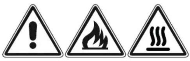
text_image
Warning sign with three triangular warning symbols: exclamation mark, flame symbol, and steam limit sign
natural_image
Illustration of a textile machine with a crossed-out X mark and steam lines (no text or symbols)WARNING – VERY IMPORTANT !
FIRE/OVERHEATING HAZARD:
- Do not place towels/cloths etc onto the hob rail or oven door handle/s whilst the product is in use or hot.
TO AVOID DAMAGE TO THE APPLIANCE:
- Do not lift/move the cooker by the hob rail or oven door handle/s. - Do not lean on the hob rail or oven door handle/s.

text_image
Hob rail (some models only) Door handle/s This figure is indicative onlyAdvice for the installer
IMPORTANT:
- The appliance is designed and approved for domestic use only and should not be installed in a commercial, semi commercial or communal environment.
Your product will not be guaranteed if installed in any of the above environments and could affect any third party or public liability insurances you may have. - This appliance is to be installed, regulated and adapted to function only by an authorized person in compliance with the current local regulations in force and in observation of the instructions supplied by the manufacturer.
Failure to comply with this condition will render the guarantee invalid. - Incorrect installation, for which the manufacturer accepts no responsibility, may cause personal injury or damage.
- This appliance shall only be serviced by authorized personnel.
- Always disconnect the appliance from mains power supply before carrying out any maintenance operations or repairs.
- Important: The use of suitable protective clothing/gloves is recommended when handling or cleaning of this appliance.
- The walls of the units must not be higher than work top and must be capable of resisting temperatures of 70^ above room temperature.
- We would point out that the adhesive which bonds the plastic laminate to the furniture must withstand temperatures not less than 150^ to avoid delamination.
- Do not install the appliance near inflammable materials (eg. curtains).
- Some appliances are supplied with a protective film on steel and aluminium parts. This film must be removed before using the cooker.
WARNING!
When correctly installed, your product meets all safety requirements laid down for this type of product category. However special care should be taken around the rear or the underneath of the appliance as these areas are not designed or intended to be touched and may contain sharp or rough edges, that may cause injury.

INSTALLATION
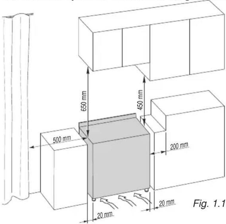
The installation conditions, concerning protection against overheating of the surfaces adjacent to the cooker, must conform to figs. 1.1 or 1.2.
The appliance must be kept no less than 200 mm away from any side wall which exceeds the height of the hob surface (figs. 1.1 or 1.2).
The veneered syntetical material and the glue used must be resistant to a temperature of
text_image
650 mm 450 mm 500 mm 200 mm 20 mm 20 mm Fig. 1.1150°C in order to avoid ungluing or deformations.
Curtains must not be fitted immediately behind appliance or within 500 mm of the sides.
If the cooker is located on a pedestal it is necessary to provide safety measures to prevent falling out.
The appliance must be housed in heat resistant units.
The walls of the units must not be higher than work top and must be capable of resisting temperatures of 70^ C above room temperature.
Do not install the appliance near inflammable materials (eg. curtains).

text_image
650 mm 450 mm 500 mm 200 mm Fig. 1.2■ Class 1
(fig. 1.1)
Gas connection made using rubber hose which must be visible and easily inspected or using rigid or flexible metal pipe.
A space of at least 2 cm must be left between the cooker and any adjacent furniture, which must not exceed the height of the cooktop.
■ Class 2
■ Subclass 1
(fig. 1.2)
Gas connection made using rigid or flexible metal pipe.
FITTING THE ADJUSTABLE FEET (TYPE A)
The adjustable feet must be fitted to the base of the cooker before use (fig. 1.3).
Rest the rear of the cooker on a piece of the polystyrene packaging exposing the base for the fitting of the feet.
Fit the 4 legs by screwing them tight into the support base as shown in figure 1.4.
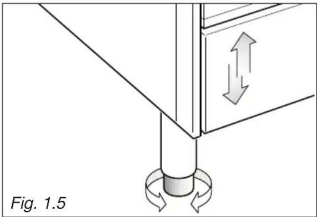
The cooker may be levelled by screwing the lower ends of the feet IN or OUT (fig. 1.5).
natural_image
Diagram of a mechanical assembly with directional arrows indicating motion, labeled Fig. 1.5 (no text or symbols on the diagram itself)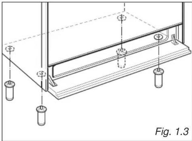
natural_image
Technical line drawing of a structural support frame with mounting holes and supports (no text or symbols)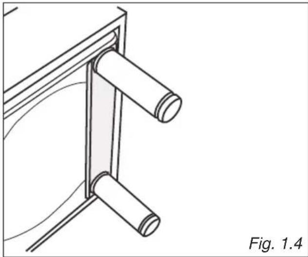
natural_image
Technical line drawing of a mechanical bracket or support structure with two cylindrical components, labeled Fig. 1.4 (no text or symbols on the diagram itself)FITTING THE ADJUSTABLE FEET (TYPE B)
The adjustable feet must be fitted to the base of the cooker before use (figs. 1.6 - 1.7).
Rest the rear of the cooker on a piece of the polystyrene packaging exposing the base for the fitting of the feet.
The cooker may be levelled by screwing the lower ends of the feet IN or OUT (fig. 1.8).

natural_image
Technical diagram of a structural support frame with vertical supports and horizontal beams, labeled Fig. 1.6 (no text or symbols on the diagram itself)
text_image
Fig. 1.8 Fig. 1.7 > 5 mm ≤ 5 mm
text_image
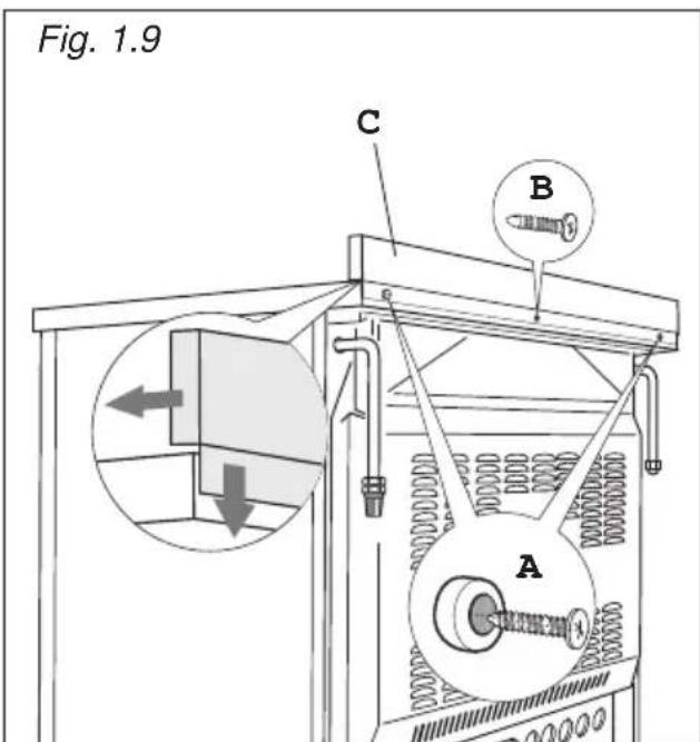
Diagram illustrating screwdriver installation steps with labeled check and dislocation instructionsBACKGUARD (SUPPLIED WITH SOME MODELS ONLY)
Before installing the cooker, assemble the backguard "C" (fig. 1.9).
- The backguard "C" can be found packed at the rear of the cooker.
- Before assembling remove any protective film/adhesive tape.
- Remove the two spacers “A” and the screw “B” from the rear of the cooktop.
- Assemble the backguard as shown in figure 7.5 and fix it by screwing the central screw "B" and the spacers "A".
text_image
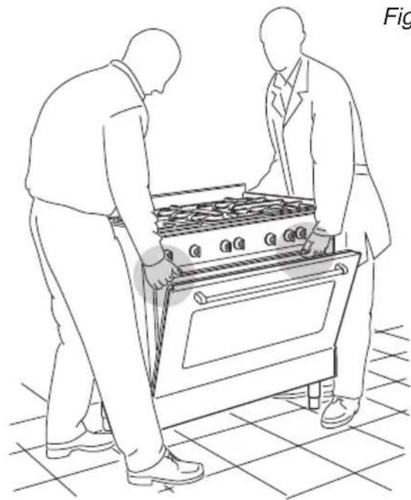
Fig. 1.9 C B AMOVING THE COOKER
WARNING: When raising cooker to upright position always ensure two people carry out this manoeuvre to prevent damage to the adjustable feet (fig. 1.10).
natural_image
Line drawing of two people inspecting a large outdoor stove (no text or symbols)Fig. 1.10
WARNING
Be careful: do not lift the cooker by the door handle when raising to the upright position (fig. 1.11).
WARNING
When moving cooker to its final position DO NOT DRAG (fig. 1.12).
Lift feet clear of floor (fig. 1.10).

text_image
Fig. 1.11 01 OF 0800000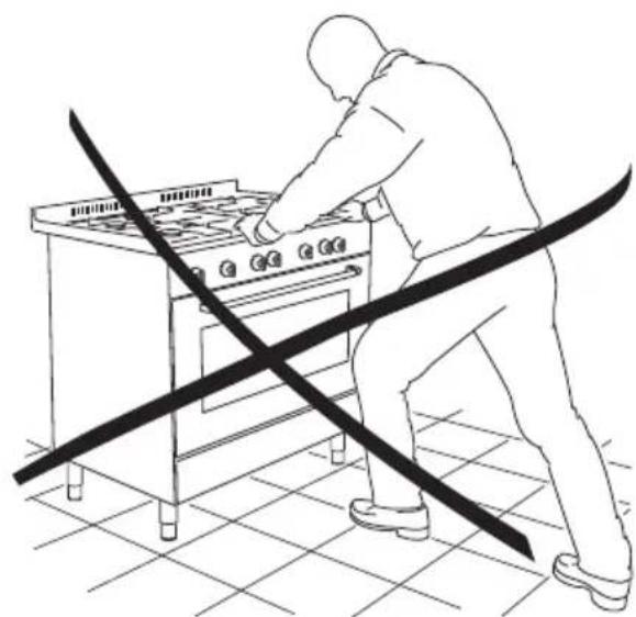
natural_image
Line drawing of a person using a portable stove with a diagonal line crossing the floor (no text or symbols)Fig. 1.12
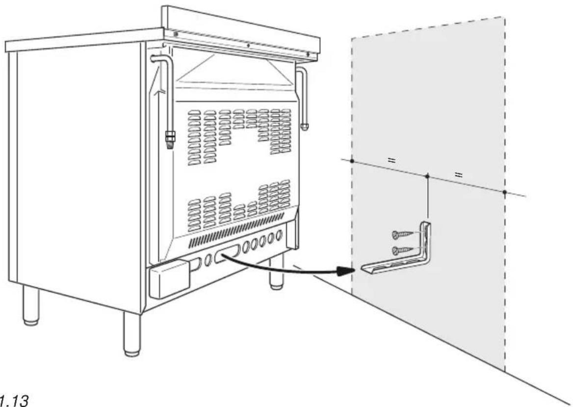
ANTI-TILT BRACKET
Warning: This appliance must be restrained to prevent accidental tipping by fitting a bracket to the rear of the appliance and securely fixing it to the wall.
To fit the anti-tilt bracket:
- After you have located where the cooker is to be positioned, mark on the wall the place where the 2 screws of the anti-tilt bracket have to be fitted. Please follow the indications given in fig. 1.13.
- Drill two 8 mm diameter holes in the wall and insert the plastic plugs supplied. Important! Before drilling the holes, check that you will not damage any pipes or electrical wires.
- Loosely attach the anti-tilt bracket with the 2 screws supplied.
- Move the cooker to the wall and adjust the height of the anti-tilt bracket so that it can engage in the slot on the cooker's back, as shown in fig. 1.13.
- Tighten the screws attaching the anti-tilt bracket.
- Push the cooker against the wall so that the anti-tilt bracket is fully inserted in the slot on the cooker's back.
Attention!
When sliding the cooker into place pay special attention not to trap the power supply cable in the stability bracket.
Pay special attention to the gas connection hose.
natural_image
Technical line drawing of a laboratory equipment cabinet with internal tubing and a separate panel assembly (no text or symbols)Fig. 1.13
VENTILATION REQUIREMENTS
The appliance must be installed in compliance with applicable local regulations concerning ventilation and the evacuation of exhaust gases.
Intensive and prolonged use may require extra ventilation, e.g. opening a window, or more efficient ventilation increasing the mechanical suction power if this is fitted.
The room where the gas appliance is to be installed must have a natural flow of air so that the gas can burn (in compliance with applicable local regulations).
The flow of air must come directly from one or more openings made in the outside walls with a free area of at least 100cm^2 (or refer to applicable local regulations).
The openings should be near the floor and preferably on the side opposite the exhaust for combustion products and must be made so that they cannot be blocked from either the inside or the outside.
When these openings cannot be made, the necessary air can come from an adjacent room which is ventilated as required, as long as it is not a bed room or a danger area (in compliance with applicable local regulations).
In this case, the kitchen door must allow the passage of the air.
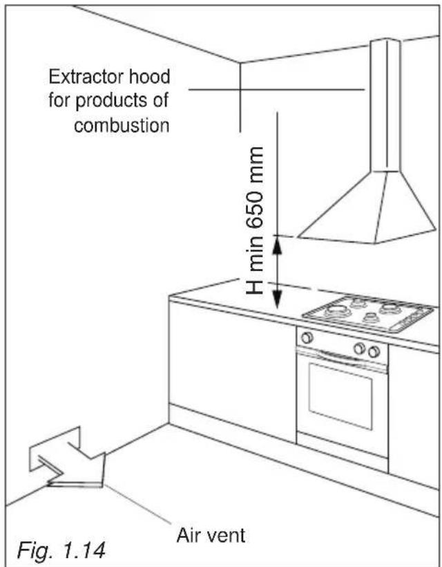
DISCHARGING PRODUCTS OF COMBUSTION
Extractor hoods connected directly to the outside must be provided, to allow the products of combustion of the gas appliance to be discharged (fig. 1.14).
If this is not possible, an electric fan may be used, attached to the external wall or the window; the fan should have a capacity to circulate air at an hourly rate of 3-5 times the total volume of the kitchen (fig. 1.15).
The fan can only be installed if the room has suitable vents to allow air to enter, as described under the heading "Choosing suitable surroundings".
text_image
Extractor hood for products of combustion H min 650 mm Fig. 1.14 Air vent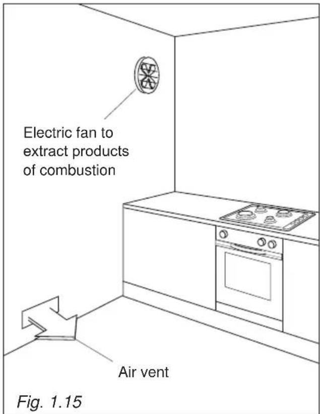
text_image
Electric fan to extract products of combustion Air vent Fig. 1.15GAS INSTALLATION REQUIREMENTS
Important!
- This appliance must be installed and serviced only by a suitably qualified, registered installer. The installer shall refer to the local standards in force.
- Failure to install the appliance correctly could invalidate any manufacturer's warranty.
- Before installation, make sure that the local distribution conditions (gas type and pressure) and the adjustment of this appliance are compatible. The appliance adjustment conditions are given on the plate or the label.
- If the gas pressure (for which the appliance is to be used) is variable or if it is not within the values indicated on the rating plate, it is mandatory to install a proper gas pressure regulator which must be adjusted to guarantee the correct operating pressure to the appliance (as per rating plate).
The regulator must be installed, adjusted and tested by a qualified technician.
- WARNING: Using the appliance with a wrong and/or variable gas pressure may be extremely dangerous and may result in serious injury to the user. Damage to the appliance could occur if not observing this condition.
The manufacturer declines every responsibility for any inconvenience resulting from the inobservance of this condition.
This appliance is supplied for use on LPG (check the gas regulation label attached on the appliance).
OR
This appliance is supplied for use on Natural gas or LPG (check the gas regulation label attached on the appliance).
- Appliances supplied for use on Natural gas: they are adjusted for this gas only and cannot be used on any other gas (LPG) without modification. The appliances are manufactured for conversion to LPG.
- Appliances supplied for use on LPG: they are adjusted for this gas only and cannot be used on any other gas (Natural gas) without modification. The appliances are manufactured for conversion to Natural gas.
If the Natural gas/LPG conversion kit is not supplied with the appliance this kit can be purchased by contacting the After-Sales Service.
FOR SOUTH AFRICA ONLY
The appliance is predisposed and adjusted to operate with the gas G30/G31 (LPG USE). Operating pressure: 2,8 kPa.
This appliance is manufactured for conversion to G20 (NATURAL GAS) if required and is supplied with a conversion kit.
This appliance must only be connected to NATURAL GAS after a NATURAL GAS conversion kit has been fitted.
CONNECTING THE APPLIANCE TO THE GAS SUPPLY
The gas connection must be carried out by an authorised person according to the relevant standards.
Ensure that the room in which the cooker is to be installed is adequately ventilated, in compliance with applicable regulations.
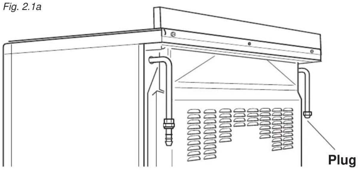
- Connect the cooker to the gas mains utilizing rigid or flexible pipes.
- The gas supply is connected at the rear of the cooker to the right or left terminal of the gas inlet pipe (fig. 2.1a). The connection pipe must not cross the rear of the appliance.
- The unused inlet pipe must be closed off with the plug and sealing washer supplied (fig. 2.1b).
text_image
Fig. 2.1a PlugFitting the plug on the unused terminal of the gas inlet pipe
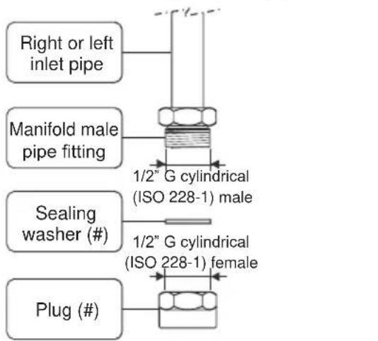
text_image
Right or left inlet pipe Manifold male pipe fitting 1/2" G cylindrical (ISO 228-1) male Sealing washer (#) 1/2" G cylindrical (ISO 228-1) female Plug (#)(#) Already fitted on the right or left inlet pipe

Fig. 2.1b
POSSIBLE GAS CONNECTIONS
GAS CONNECTION WITH A RUBBER HOSE
Important!
A rubber hose connection shall only be made if permitted by the applicable local regulations.
The gas connection is made up of:
- the terminal fitting of the inlet pipe (right-hand or left-hand);
- sealing washer;
- the appropriate hose holder (for Natural gas or LPG). If not supplied with the appliance it can be purchased by contacting the After-Sales Service.
Connecting the cooker to Natural gas
- If not already fitted, fit the Natural gas hose holder on the inlet pipe, making sure that you place the sealing washer between them (as shown in fig. 2.2).
- Connect the cooker to the gas supply using a suitable rubber hose (internal diameter 15 mm).
The hose must comply with the applicable local regulations and be of the correct construction for the type of gas being used.
- Make sure that the hose is tightly and securely fitted at both ends.
- Use a standard hose clamp (not supplied) to fasten the hose.
Connecting the cooker to LPG
- If not already fitted, fit the LPG hose holder on the inlet pipe, making sure that you place the sealing washer between them (as shown in fig. 2.2).
- Connect the cooker to the gas supply using a suitable rubber hose (internal diameter 6 mm).
The hose must comply with the applicable local regulations and be of the correct construction for the type of gas being used.
- Make sure that the hose is tightly and securely fitted at both ends.
- Use a standard hose clamp (not supplied) to fasten the hose.
- Install a gas pressure regulator.
Important!
To comply with applicable local regulations, a gas pressure regulator (conforming to the local regulations in force) must be installed when connecting the cooker to an LPG cylinder.
When connecting the cooker to the gas supply with a rubber hose, make sure that
- the hose is as short as possible, without twists or kinks.
- the hose is not longer than 750 mm (or refer to applicable local regulations) and does not come into contact with sharp edges, corners or moving parts. Use a single rubber hose only; never connect the appliance with more than one rubber hose.
- the hose is not under tension, twisted, kinked, or too tightly bent, neither while the appliance is in use nor while it is being connected or disconnected.
- the hose does not come into contact with any part of the cooker with a surface temperature of 70^ C or above (or refer to applicable local regulations).
- the hose is not subject to excessive heat by direct exposure to flue products or by contact with hot surfaces.
-
the hose can easily be inspected along its entire length to check its condition.
-
the hose is replaced at the printed due date or if it shows signs of wear or damage, and replaced regardless of its condition after a maximum of three years.
- you inform the customer that the gas cylinder valve or the gas supply valve immediately by the cooker should be closed when the cooker is not in use.
- you inform the customer that the hose should not be subjected to corrosion by acidic cleaning agents.
After connecting the cooker to the gas supply, make sure that you
- check that the connections are correctly sealed using a soapy solution, but never a naked flame.
- check whether the injectors are correct for the type of gas being used. If not, follow the instructions under "GAS MAINTENANCE".
- replace the sealing washer/s on the slightest sign of deformation or imperfection. The sealing washer/s is/are the part/s which guarantee/s a good seal in the gas connection.
- use two spanners when fitting the hose holder (fig. 2.2).
Gas connection with rubber hose holders
Note: if not already fitted on the inlet pipe, the hose holders are supplied with the product in a separate kit; if not supplied with the appliance they can be purchased by contacting the After-Sales Service.
(Important: to be used ONLY IF PERMITTED by the local applicable regulations)
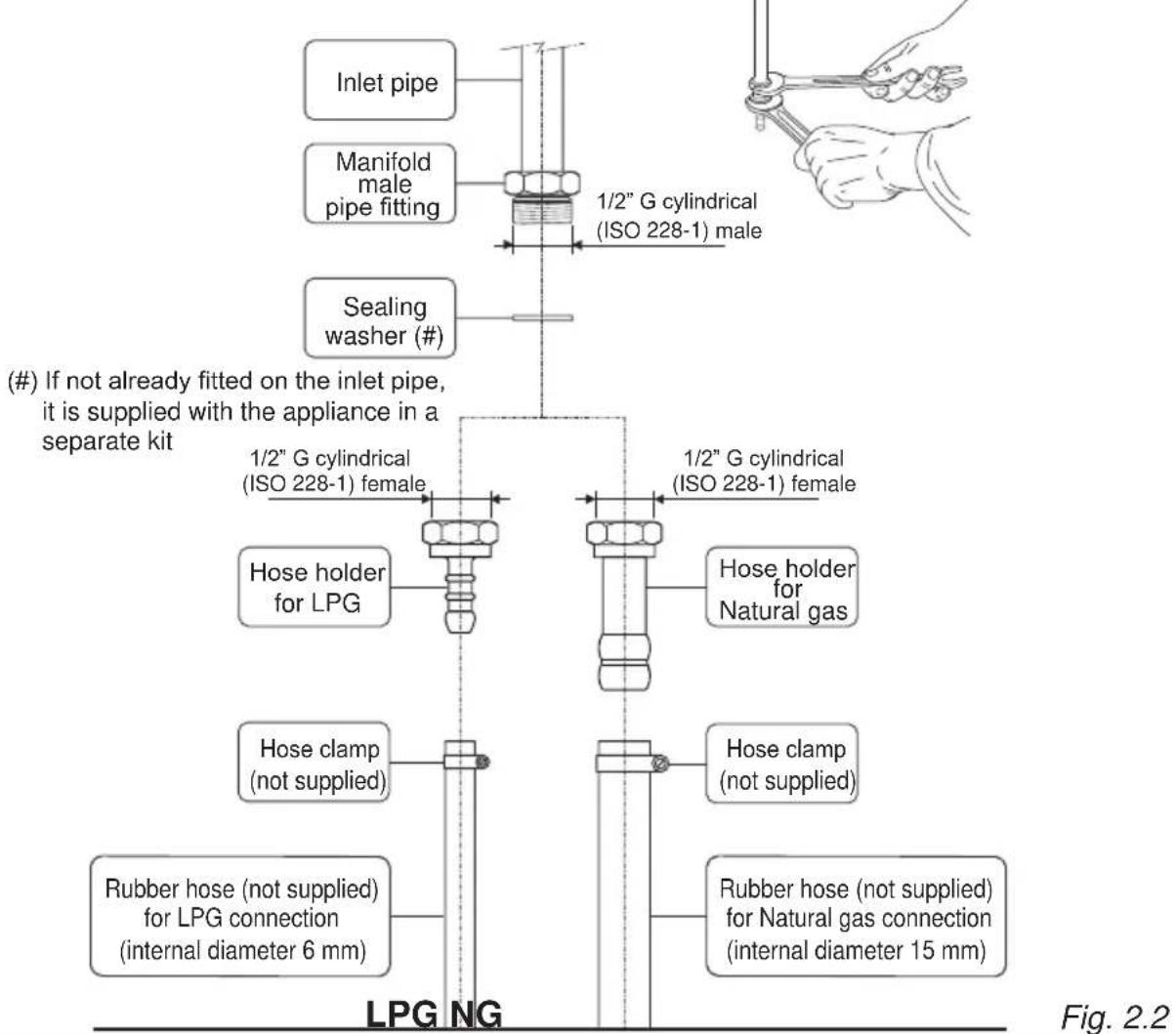
text_image
(#) If not already fitted on the inlet pipe, it is supplied with the appliance in a separate kit Inlet pipe Manifold male pipe fitting Sealing washer (#) 1/2" G cylindrical (ISO 228-1) male 1/2" G cylindrical (ISO 228-1) female Hose holder for LPG Hose clamp (not supplied) Rubber hose (not supplied) for LPG connection (internal diameter 6 mm) 1/2" G cylindrical (ISO 228-1) female Hose holder for Natural gas Hose clamp (not supplied) Rubber hose (not supplied) for Natural gas connection (internal diameter 15 mm) LPG NG Fig. 2.2GAS CONNECTION WITH RIGID PIPES OR A FLEXIBLE PIPE
The gas connection is made up of:
- the terminal fitting of the inlet pipe (right-hand or left-hand)
- sealing washer.
Important!
If fitted, remove the hose holder from the terminal fitting of the inlet pipe.
When connecting the cooker to the gas supply with rigid pipes or a flexible pipe, make sure that
- you use rigid pipes or a flexible pipe complying with applicable local regulations. The flexible pipe shall be of the correct construction for the type of gas being used.
- if compression fittings are used, you tighten them firmly using two spanners (fig. 2.3).
- the connection with rigid metal pipes does not cause stress or pressure to the gas piping.
- the flexible pipe is not under tension, twisted, kinked or too tightly bent, neither while the appliance is in use nor while it is being connected or disconnected.
- the flexible pipe does not exceed 2000 mm in length (or refer to applicable local regulations) and does not come into contact with sharp edges, corners or moving parts. Use a single flexible pipe only; never connect the cooker with more than one flexible pipe.
- the flexible pipe can easily be inspected along its entire length to check its condition; if it has an expiry date, it should be replaced before that date.
- if using a flexible pipe which is not entirely made of metal, make sure that it does not come into contact with any part of the cooker with a surface temperature of 70^ or above (or refer to applicable local regulations).
- the rigid or flexible pipe is not subject to excessive heat by direct exposure to flue products or by contact with hot surfaces.
- the rigid or flexible pipe is replaced if it shows signs of wear or damage.
- a gas pressure regulator, in compliance with the applicable local regulations, is installed when connecting to an LPG cylinder.
- you inform the customer that the cylinder valve or the supply valve immediately by the appliance should be closed when the cooker is not in use.
- you inform the customer that the rigid or flexible pipe should not be subjected to corrosion by acidic cleaning agents.
After connecting the cooker to the gas supply, make sure that you
- check that the connections are correctly sealed using a soapy solution, but never a naked flame.
- check whether the injectors are correct for the type of gas being used. If not, follow the instructions under “GAS MAINTENANCE”.
- replace the sealing washer/s on the slightest sign of deformation or imperfection. The sealing washer/s is/are the part/s which guarantee/s a good seal in the gas connection.
- use two spanners when connecting the rigid or flexible pipe (fig. 2.3).
Gas connection with rigid or flexible pipe
Note: if already fitted on the inlet pipe, remove the rubber hose holder
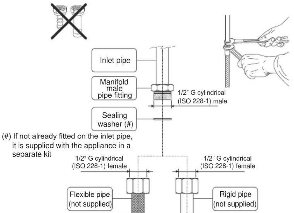
text_image
(#) If not already fitted on the inlet pipe, it is supplied with the appliance in a separate kit Inlet pipe Manifold male pipe fitting Sealing washer (#) 1/2" G cylindrical (ISO 228-1) male 1/2" G cylindrical (ISO 228-1) female Flexible pipe (not supplied) 1/2" G cylindrical (ISO 228-1) female Rigid pipe (not supplied)Fig. 2.3
GAS MAINTENANCE
For the gas category check the data label attached on the appliance.
| TABLE FOR THE CHOICE OF THE INJECTORS | ||||
| Cat: I 3+ | G30/G3128-30/37 mbar | |||
| BURNERS | Nominal power [kW] | Reduced power [kW] | ∅ injector[1/100 mm] | |
| Auxiliary (A) 1,00 0,40 50 | ||||
| Semi-rapid (SR) 1,75 0,45 65 | ||||
| Rapid (R) 3,00 0,75 85 | ||||
| Double-ring compact (DCC) | 4,00 1,50 100 | |||
| Dual (D) | inner crown 0,80 | 0,40 44 | ||
| outer crown | 4,20(3,80 at G30/G31) | 1,50 98 | ||
| TABLE FOR THE CHOICE OF THE INJECTORS | |||||
| Cat: II 2H 3+ | G30/G3128-30/37 mbar | G2020 mbar | |||
| Cat: II 2E 3+ | G30/G3128-30/37 mbar | G20/G2520/25 mbar | |||
| BURNERS | Nominal power [kW] | Reduced power [kW] | ∅ injector[1/100 mm] | ∅ injector[1/100 mm] | |
| Auxiliary (A) 1,00 0,40 50 72 (X) | |||||
| Semi-rapid (SR) 1,75 0,45 65 97 (Z) | |||||
| Rapid (R) 3,00 0,75 85 128 (H3) | |||||
| Double-ring compact (DCC) | 4,00 1,50 100 150 (H3) | ||||
| Dual (D) | inner crown | 0,80 0,40 44 68 (H1) | |||
| outer crown | 4,20(3,80 at G30/G31) | 1,50 98 155 (H3) | |||
(*) Reference value
| AIR VENT NECESSARY FOR GAS COMBUSTION = (2 m3/h x kW) | ||
| BURNERS Air necessary for combustion [m 3/h] | ||
| Auxiliary (A) | 2,00 | |
| Semi-rapid (SR) | 3,50 | |
| Rapid (R) | 6,00 | |
| Double-ring compact (DCC) | 8,00 | |
| Dual (D) | inner crown | 1,60 |
| outer crown | 8,40 (7,60 at G30/G31) | |
| inner & outer crown | 10,00 (9,20 at G30/G31) | |
LUBRICATION OF THE GAS TAPS
• In case of difficulty in the gas taps operation, call Service.
IMPORTANT
All intervention regarding installation maintenance of the appliance must be fulfilled with original factory parts. The manufacturer declines any liability resulting from the non-compliance of this obligation.
REPLACEMENT OF THE INJECTORS OF THE BURNERS
Select the injectors to be replaced according to the "Table for the choice of the injectors".
The nozzle diameters, expressed in hundredths of a millimetre, are marked on the body of each injector.
If the injectors are not supplied they can be obtained from the "Service Centre".
REPLACEMENT OF THE INJECTORS OF THE COOKTOP BURNERS
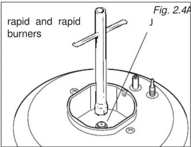
To replace the injectors proceed as follows:
- Remove pan supports and burners from the cooktop.
- Using a wrench, substitute the nozzle injectors "J" (figs. 2.4, 2.5a, 2.5b) with those most suitable for the kind of gas for which it is to be used.
The burners are conceived in such a way so as not to require the regulation of the primary air.
ADJUSTING OF THE MINIMUM OF THE TOP BURNERS
In the minimum position the flame must have a length of about 4 mm and must remain lit even with a quick turn from the maximum position to that of minimum.
The procedure for adjusting the minimum gas rate setting is described below.
• Light the burner.
- Set the gas valve to the "minimum rate" position.
- Remove the knob.
- Using a screwdriver turn the screw "A" until adjustment is correct (fig. 2.6).
- Dual burner: For the dual burner set the minimum (as indicated above) for both the gas valves (one for the inner and one for the outer ring). The operations must be carried out one gas valve at a time.
Normally for LPG (G30/G31), tighten up the regulation screw.
text_image
rapid and rapid burners Fig. 2.4A JFig. 2.4 Auxiliary

text_image
Double-ring compact J Fig. 2.5a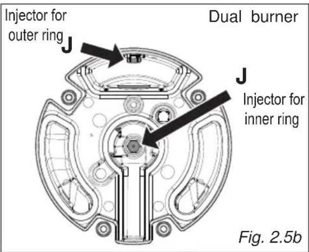
text_image
Injector for outer ring J Dual burner J Injector for inner ring Fig. 2.5b
text_image
A Fig. 2.6IMPORTANT: The appliance must be installed by a qualified technician according with the current local regulations and in compliance with the manufacturer instructions. Incorrect installation might cause harm and damage to people, animals or objects, for which the manufacturer accepts no responsibility.
Before carrying out any work on the electrical section of the appliance, it must be disconnected from the mains.
Connection to a good earth wiring system is absolutely essential.
The manufacturer accepts no responsibility for any inconvenience caused by failure to comply with this rule.
GENERAL
- Connection to the mains must be carried out by qualified personnel in accordance with current regulations.
- The appliance must be connected to the mains checking that the voltage corresponds to the value given in the rating plate and that the electrical cable sections can withstand the load specified on the plate.
- Models supplied with plug: The plug must be connected to an earthed socket in compliance with safety standards.
- Models supplied without plug: The appliance is supplied without a power supply plug and therefore if you are not connecting directly to the mains, a standardized plug suitable for the load must be fitted.
- The appliance can be connected directly to the mains placing an omnipolar switch with minimum opening between the contacts of 3 mm between the appliance and the mains.
- The power supply cable must not touch the hot parts and must be positioned so that it does not exceed 75°C at any point.
- Once the appliance has been installed, the switch or socket must always be accessible.
- If the power supply cable is damaged it must be substituted by a suitable cable available in the after sales service.
N.B. For connection to the mains, do not use adapters, reducers or branching devices as they can cause overheating and burning.
If the installation requires alterations to the domestic electrical system or if the socket and appliance plug are incompatible, call an expert.
He should also check that the socket cable section is suitable for the power absorbed by the appliance.
Models with electrical hotplates
ELECTRICAL FEEDER CABLE CONNECTION
Important! This appliance must be connected to the electricity supply only by an authorised person.
WARNING: If the power supply cable is damaged, it must be replaced only by an authorised service agent in order to avoid a hazard.
To connect the supply cable:
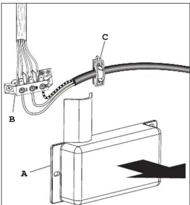
- Remove the screws securing the cover "A" on the rear of the cooker (fig. 3.1a).
- Feed the supply cable through the cable clamp "C" (fig. 3.1a). The supply cable must be of a suitable size for the current requirements of the appliance; see the section "Feeder cable specifications".
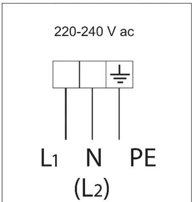
- Connect the wires to the terminal block "B" as shown in the diagram in figure 3.1b.
• Take up any slack in the cable and secure with the cable clamp "C". - Replace the cover "A".
Note: The earth conductor must be left about 3 cm longer than the others.
FEEDER CABLE SPECIFICATIONS
- Type H05RR-F
- or Type H05V2V2-F" (resistance to temperatures of 90°C)
220-240 V ac 3 x 2,5 mm ^2 (**)
(**) Connection with wall box connection
text_image
Technical diagram showing cable connection with labeled components A, B, and C, including a magnified view of component A.Fig. 3.1a
text_image
220-240 V ac L1 N PE (L2)Fig. 3.1b
Models without electrical hotplates
ELECTRICAL FEEDER CABLE CONNECTION
Important! This appliance must be connected to the electricity supply only by an authorised person.
WARNING: If the power supply cable is damaged, it must be replaced only by an authorised service agent in order to avoid a hazard.
To connect the supply cable:
- Remove the screw securing the cover "A" on the rear of the cooker (fig. 3.2a).
- Unscrew cable clamp "D" (fig. 3.2b).
- Connect the wires to the terminal block "B" as shown in the diagram in figure 3.2c.
• Take up any slack in the cable and secure with the cable clamp "D". - Replace the cover "A".
Note: The earth conductor must be left about 3 cm longer than the others.

text_image
Fig. 3.2a AFEEDER CABLE SPECIFICATIONS
- Type H05RR-F
- or Type H05V2V2-F" (resistance to temperatures of 90°C)
220-240 V ac 3 X 1,5 mm²(*) (**)
or Type SJT
220 V ac AWG 14/3 (*) (**)
(*) Connection possible with plug and outlet
(**) Connection with wall box connection.

text_image
Fig. 3.2b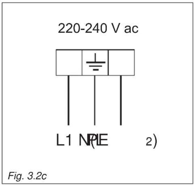
text_image
220-240 V ac L1 NPIE 2) Fig. 3.2cAdvice for the user
Fig. 1.1 Fig. 1.2
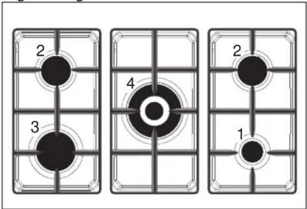
text_image
2 3 4 2 1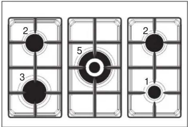
text_image
2 3 5 2 1Fig. 1.3 Fig. 1.4

text_image
2 4 7 6 1 2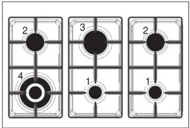
flowchart
graph TD
    A["2"] --> B["3"]
    C["4"] --> D["1"]
    E["2"] --> F["1"]
Fig. 1.5 Fig. 1.6
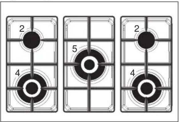
text_image
2 4 5 2 4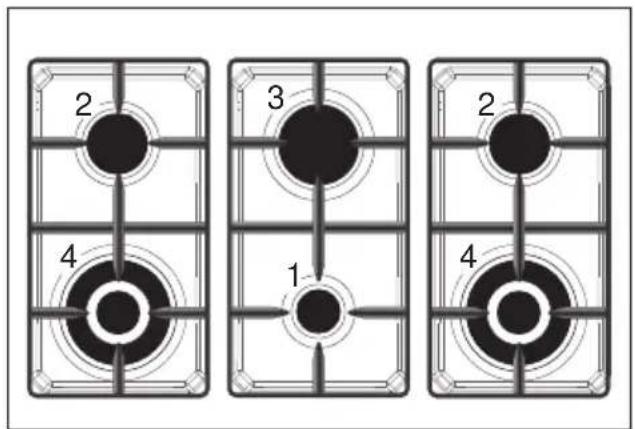
text_image
2 3 2 4 1 4NOTE:
This figures are indicative only.
GAS BURNERS
- Auxiliary burner (A) 1,00 kW
- Semi-rapid burner (SR) 1,75 kW
- Rapid burner (R) 3,00 kW
- Double-ring compact (DCC) 4,00 KW
- Dual burner (DB) (*) 5000 kW or 4600 for G30/G31
- Electrical plate (∅ 145 mm) 1000 W Normal or 1500 W Rapid (red dot)
- Electrical plate (∅ 180 mm) 1500 W Normal or 2000 W Rapid (red dot)
(*) IMPORTANT: The Dual burner is controlled by two separate knobs; one knob for the inner ring only and one knob for the outer ring only.
The inner and outer ring can be used together or separately.
After using the dual burner check both the control knobs are in the closed "●" (off) position.
Notes:
- The electric ignition is incorporated in the thermostat control knob.
- The appliance has a safety valve system fitted, the flow of gas will be stopped if and when the flame should accidentally go out.
CAUTION:
If the burner is accidentally extinguished, turn the gas off at the control knob and wait at least 1 minute before attempting to relight.
CAUTION:
Gas appliances produce heat and humidity in the environment in which they are installed. Ensure that the cooking area is well ventilated by opening the natural ventilation grilles or by installing an extractor hood connected to an outlet duct.
CAUTION:
If the appliance is used for a prolonged time it may be necessary to provide further ventilation by opening a window or by increasing the suction power of the extractor hood (if fitted).
text_image
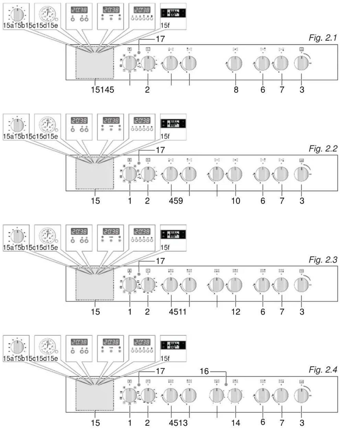
15a15b15c15d15e 20:38 20:38 20:38 15f 17 Fig. 2.1 15145 2 8 6 7 3 17 Fig. 2.2 15a15b15c15d15e 20:38 20:38 20:38 15f 15 1 2 459 10 6 7 3 Fig. 2.3 15a15b15c15d15e 20:38 20:38 20:38 15f 17 4511 12 6 7 3 Fig. 2.4 15a15b15c15d15e 20:38 20:38 20:38 15f 17 16 Fig. 2.4NOTES:
The knobs and symbols may vary.
The symbols may be printed on the knob itself.
CONTROLS DESCRIPTION
- Oven selector control knob
- Oven thermostat control knob
- Rotisserie control knob - Depending on the models (optional component, some models only)
- Front left burner control knob
- Rear left burner control knob
- Rear right burner control knob
- Front right burner control knob
- Central burner control knob
- Central burner control knob (inner ring only)
- Central burner control knob (outer ring only)
- Front central burner control knob
- Rear central burner control knob
- Front electrical plate control knob
- Rear electrical plate control knob
- Depending on the models (optional component, some models only):
a. 60' or 120' alarm or Timer (120 minutes cut-off) control knob
b. Electric clock/programmer (start-end cooking)
c. Electronic clock/end cooking timer or Electronic clock with alarm
d. Clock and timer with "Touch-Control" keys
e. Electronic clock/programmer (start-end cooking)
f. Electronic clock/programmer
-
electrical plate indicator light
-
Oven thermostat indicator light
Note (some models only): Your appliance has been fitted with a cooling fan to achieve optimum efficiency of the controls and to ensure lower surface temperatures are maintained. When the oven is operating the cooling fan motor switches ON/OFF depending on temperature. Depending on cooking temperatures and times, the cooling fan may run on even after appliance has been switched off. The duration of this time is dependent on previous cooking temperature and duration.
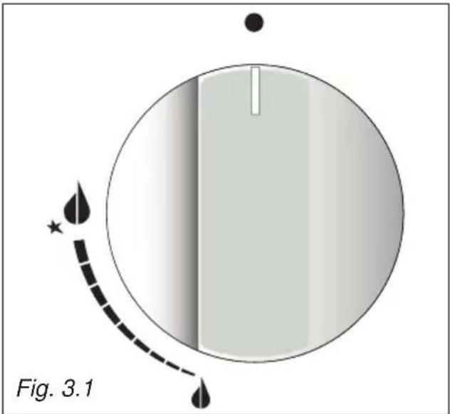
GAS BURNERS
Gas flow to the burners is adjusted by turning the knobs (illustrated in figs. 3.1 - 3.2) which control the safety valves.
Make the symbol of the knob match with the indicator on the control panel (or vice versa) to obtain:
- symbol

closed valve
- symbol

maximum aperture or flow
- symbol

minimum aperture or flow
√ The maximum aperture position permits rapid boiling of liquids, whereas the minimum aperture position allows slower warming of food or maintaining boiling conditions of liquids.
√ To reduce the gas flow to minimum rotate the knob further anti-clockwise to point the indicator towards the small flame symbol.
√ Other intermediate operating adjustments can be achieved by positioning the indicator between the maximum and minimum aperture positions, and never between the maximum aperture and closed positions.
text_image
Fig. 3.1NOTES:
The knobs and symbols may vary. The symbols may be printed on the knob itself.
Caution!
Do not cover the hob with aluminium foils.
Caution!
The cooking hob becomes very hot during operation.
Keep children well out of reach.
N.B. When the cooker is not being used, set the gas knobs to their closed positions and also close the cock valve on the gas bottle or the main gas supply line.
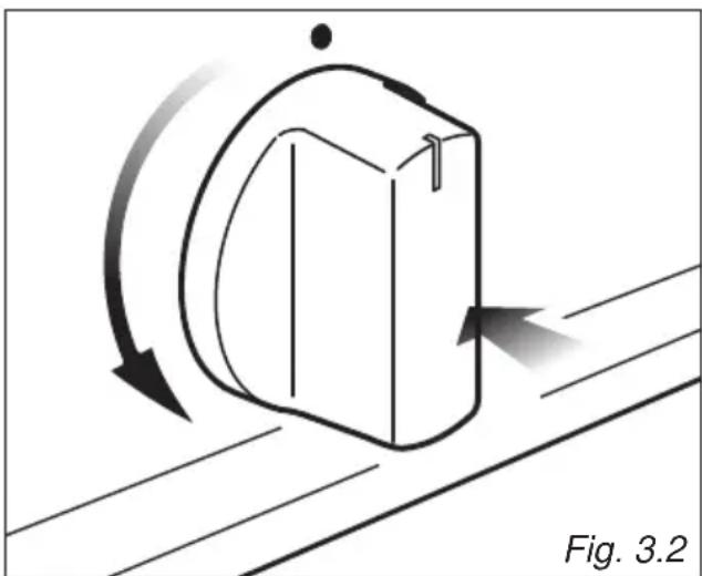
To ignite the burner, the following instructions are to be followed:
- Press in the corresponding knob and turn counter-clockwise (fig. 3.2) to the full flame position marked by the symbol (fig. 3.1) and hold the knob in until the flame has been lit.
In the case of a mains failure light the burner with a match or lighted taper.
- Wait for about ten seconds after the gas burner has been lit before letting go of the knob (valve activation delay).
- Adjust the gas valve to the desired position.
If the burner flame should go out for some reason, the safety valve will automatically stop the gas flow.
To re-light the burner, return the knob to the closed “●” position, wait for at least
1 minute and then repeat the lighting procedure.
If your local gas supply makes it difficult to light the burner with the knob set to maximum, set the knob to minimum and repeat the operation.
DUAL BURNER - SOME MODELS ONLY
The Dual Burner is a very flexible burner which allows different regulations and optimal cooking.
It is composed by one inner and one outer crown: the inner and outer crown can be used together or separately.
The Dual burner is controlled by two separate knobs:
- one knob for the inner crown only ("symbol identifying the control knob);
- one knob for the outer crown only ("○ symbol identifying the control knob).
The Dual burner can be used:
• as a small burner (flame produced only by the inner crown);
• as a Ultra-rapid burner (flame produced only by the outer crown);
• as a high-power burner (all flames produced simultaneously by inner and outer crown).
natural_image
Diagram of a mechanical component with directional arrows indicating motion, labeled Fig. 3.2 (no text or symbols on the diagram itself)
IMPORTANT: After using the dual burner check both the control knobs are in the closed “●” position.
CHOICE OF THE BURNER
On the control panel, near every knob there is a diagram that indicates which burner is controlled by that knob.
The suitable burner must be chosen according to the diameter and the capacity used.
The burners and pans must be used in accordance with the following instructions:
| DIAMETERS OF PANS WHICH MAY BE USED ON THE BURNERS | ||
| BURNERS MINIMUM MAXIMUM | ||
| Auxiliary or Dual (inner crown only) (with ‘closed’ prongs of pan support) |  | 6 cm 14 cm |
| Auxiliary or Dual (inner crown only) (with ‘open’ prongs of pan support) |  | 12 (*) cm 14 cm |
| Semi-rapid 16 cm 24 cm | ||
| Rapid 24 cm 26 cm | ||
| Double-ring compact | 26 cm 28 cm | |
| Dual (outer crown only) 24 cm 26 cm | ||
| Dual (inner+outer crown) | 26 cm 28 cm | |
| Wok (**) - Max 36 cm | ||
| do not use pans with concave or convex bases | ||
(*) with grill for small cookware: minimum diameter 6 cm.
(**) with Double-ring compact and Dual burner and with wok pan adapter supplied.
It is important that the diameter of the pot be suitable to the potentiality of the burner so as not to compromise the high output of the burners and therefore energy waste.
A small pot on a large burner does not give you a boiling point in a shorter amount of time since the capacity of heat absorption of a liquid mass depends on the volume and the surface of the pot.
CAUTION: Make sure the pans are central to the burner for maximum stability and greater efficiency.
Make sure the pans are not in contact with the control knobs, otherwise the flame could overheat the knobs and permanently damage them.
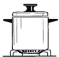

Fig. 3.3
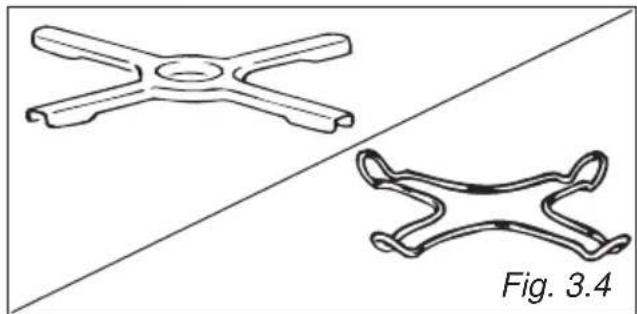
SMALL PAN ADAPTER (Some models only) (Type A) (fig. 3.4)
This adapter is to be placed on top of the (smaller) auxiliary burner when using small diameter pans, in order to prevent them from tipping over.
It can be used also on the dual burner when using the inner ring only with small diameter pans. Do not use this grate when using the outer ring or the outer & inner ring of the dual burner.
natural_image
Two technical line drawings of a mechanical component, one cross-shaped and one curved, against a diagonal background (no text or symbols)SMALL PAN ADAPTER (Some models only) (Type B)
This adapter is to be placed:
- on top of the (smaller) auxiliary burner when using small diameter pans, in order to prevent them from tipping over;
- It can be used also on the dual burner when using the inner ring only with small diameter pans. Do not use this grate when using the outer ring or the outer & inner ring of the dual burner.
IMPORTANT: To avoid any burner malfunction, this adapter MUST be placed correctly (figs. 3.5, 3.6).

text_image
CORRECT WRONG Fig. 3.5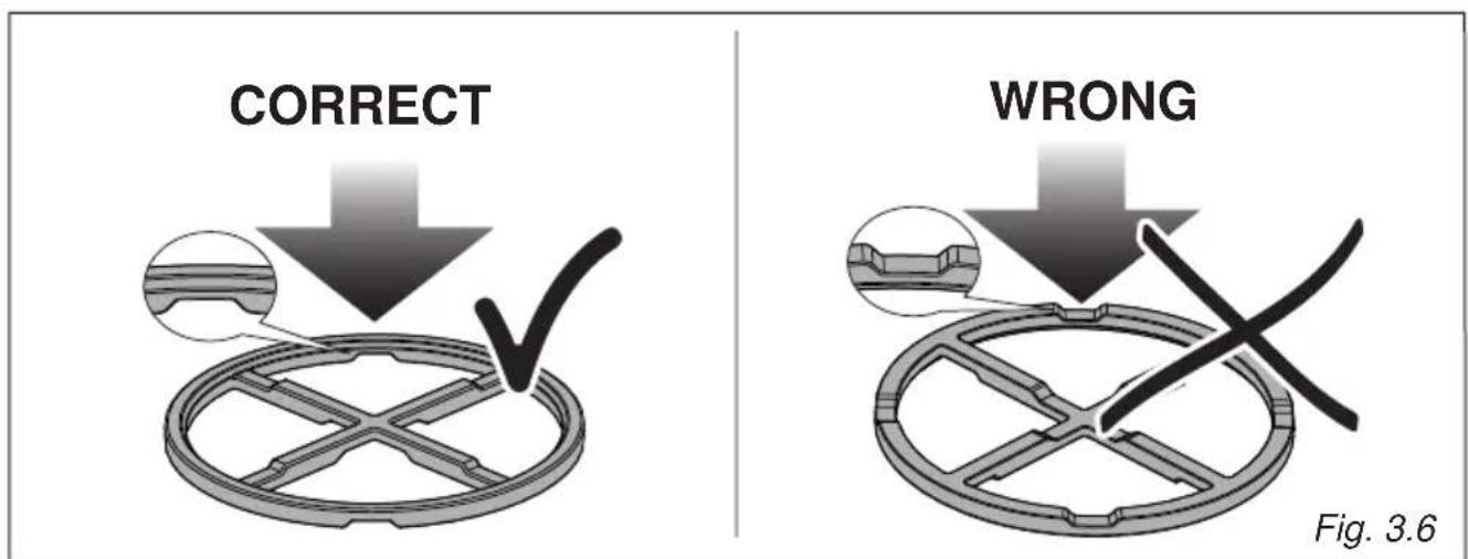
text_image
CORRECT WRONG Fig. 3.6WOK STAND (Some models only) (figs. 3.7a - 3.7b)
This special grille for woks should be placed over the pan-rest for the Double-ring compact and Dual burner.
Warning:
• Using woks without this special grille may cause the burner to malfunction.
- Do not use the grille for ordinary, flat-bottomed saucepans.
IMPORTANT:
The special grille for wok pans MUST BE PLACED ONLY over the pan-rest for the Double-ring compact and Dual burner.

text_image
CORRECT
text_image
WRONG Fig. 3.7bFig. 3.7aHOTPLATES
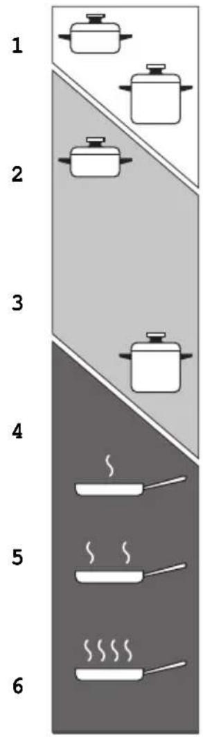
NORMAL HOTPLATES
To switch on the normal hotplate, turn the knob (fig. 3.8) onto the desired position; the numbers 1 to 6 indicate the working positions with the increase of temperature according to the number.
Once boiling point has been reached, reduce the input according to the heating intensity desired, keeping in mind that the plate will continue to heat for 5 minutes after having been turned off.
RAPID HOTPLATE (red dot)
The control knob of the rapid hotplates is similar to that of a normal plate with 6 working positions (fig. 3.8).
The rapid hotplate incorporate a heat limitator.
The features of this plate, which is equipped with a heat limiter, allow:
- reaching the temperature rapidly;
• maximum exploitation of the input with flat bottom pots; - the limitation of input in the case of unsuitable pots.
Caution! Do not cover the hob with aluminium foils.
NOTES: The knob and symbols may vary.
The symbols may be printed on the knob itself.

text_image
0 1 2 3 4 5 6 Fig. 3.8PROPER USE OF THE ELECTRIC HOTPLATE (fig. 3.9)
When the pan comes to the boil, turn the heat down to the level desired.
Remember that the hotplate will continue to produce heat for about five minutes after it has been turned off.
While using the electric hotplate, you must:
- avoid keeping it on without something on it;
- avoid pouring liquids on it while it is hot;
- use flat-bottomed (electric hotplate type) pots and pans only
- use cooking receptacles which cover as much of the surface of the hotplate as possible.
• to save electricity, use lids whenever possible. - never cook food directly on the hotplate: always use a pan or suitable container.
An indicator light located on the control panel signals that the hotplate is operating
Never cook the food directly on the hotplate, but in special pans or containers.
Caution! The cooking hob becomes very hot during operation.
Keep children well out of reach.
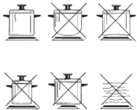
Fig. 3.9
text_image
1 2 3 4 5 6
Heating

Cooking

Roasting-frying
Fig. 3.10
ELECTRIC HOTPLATE USAGE TABLE
| Position of switch | TYPE OF COOKING |
| 0 | Switched OFF |
| 12 | For melting operations (butter, chocolate). |
| 2 | To maintain food hot and to heat small quantities of liquid (sauces, eggs). |
| 3 | To heat bigger quantities; to whip creams and sauces. (vegetables, fruits, soups). |
| 34 | Slow boiling, i.e.: boiled meats, spaghetti, soups, continuations of steam, cooking of roasts, stews, potatoes. |
| 4 | For every kind of frying, cutlets, uncovered cooking, i.e.: risotto. |
| 45 | Browning of meats, roasted potatoes, fried ☐sh, omelet-tes, and for boiling large quantities of water. |
| 6 | Fast frying, grilled steaks, etc. |
After a short period of use, experience will teach you which setting is the right one for your needs.
FAN WITH GRILL MODELS
TYPE 1 (WITHOUT ROTISSERIE)
Function selector knob Fig. 4.1a

text_image
0NOTES: The knob and symbols may vary. The symbols may be printed on the knob itself.
GENERAL FEATURES
The heating and cooking in electrical hot air ovens take place by forced convection.
The two elements which make this process take place are:
- circular element;
- grill element.
NOTE:
Upon first use, it is advisable to operate the oven at the maximum temperature for 60 minutes in the position 📁 to eliminate possible traces of grease on the heating elements.
Repeat the operation for another 20 minutes with the grill element on as explained in the chapters "TRADITIONAL GRILLING" and "USE OF THE GRILL".
TYPE 2 (WITH ROTISSERIE)
Function selector knob Fig. 4.1b
text_image
0 1 2 3 4 5 6 7 8 9 10 11 12 13 14 15 16 17 18 19 20 21 22 23 24 25 26 27 28 29 30 31 32 33 34 35 36 37 38 39 40 41 42 43 44 45 46 47 48 49 50NOTES: The knob and symbols may vary. The symbols may be printed on the knob itself.
OPERATING PRINCIPLES
Heating and cooking in the fan oven are obtained in the following ways:
a. by forced convection
A fan sucks in the air contained in the oven, which circulates it through the circular heating element and then forced back into the oven by the fan. Before the hot air is sucked back again by the fan to repeat the described cycle, it envelops the food in the oven, provoking a complete and rapid cooking. It is possible to cook several dishes simultaneously.
b. by radiation
The heat is radiated by the infrared grill element.
c. by radiation and ventilation
The radiated heat from the infrared grill element is distributed throughout the oven by the fan.
d. by ventilation
The food is defrosted by using the fan only function without heat.
PLURIFUNCTION MODELS
TYPE 1 (WITHOUT ROTISSERIE) TYPE 2 (WITH ROTISSERIE)
Function selector knob
Fig. 4.2a

text_image
0 1 2 3 4 5 6 7 8 9 10NOTES: The knob and symbols may vary. The symbols may be printed on the knob itself.
Function selector knob
Fig. 4.2b

text_image
0 1 2 3 4 5 6 7 8NOTES: The knob and symbols may vary. The symbols may be printed on the knob itself.
GENERAL FEATURES
As its name indicates, this is an oven that presents particular features from an operational point of view.
In fact, it is possible to insert no.8 (figs. 4.2a, 4.2b) different programs to satisfy every cooking need.
The 8 positions, thermostatically controlled, are obtained by 3 heating elements which are:
- Upper element;
- Lower element;
- Grill element.
NOTE:
Upon first use, it is advisable to operate the oven at the maximum temperature for 60 minutes in the position ☐ to eliminate possible traces of grease on the heating elements.
Repeat the operation for another 20 minutes with the grill element on as explained in the chapters "TRADITIONAL GRILLING" and "USE OF THE GRILL".
OPERATING PRINCIPLES
Heating and cooking in the plurifunction oven are obtained in the following ways:
a. by normal convection
The heat is produced by the upper and lower heating elements.
b. by semi-forced convection
The heat produced by the upper and lower heating elements is distributed throughout the oven by the fan.
c. by radiation
The heat is radiated by the infrared grill element.
d. by radiation and ventilation
The radiated heat from the infrared grill element is distributed throughout the oven by the fan.
e. by ventilation
The food is defrosted by using the fan only function without heat.
MULTIFUNCTION MODELS
TYPE 1 (WITHOUT ROTISSERIE) TYPE 2 (WITH ROTISSERIE)
Function
selector
knob
Fig. 4.3a
text_image
0 A B C D E F G H I J K L M N O P Q R S T U V W X Y ZNOTES: The knob and symbols may vary. The symbols may be printed on the knob itself.
Function
selector
knob
Fig. 4.3b

text_image
0 1 2 3 4 5 6 7 8 9 10NOTES: The knob and symbols may vary. The symbols may be printed on the knob itself.
GENERAL FEATURES
As its name indicates, this is an oven that presents particular features from an operational point of view.
In fact, it is possible to insert no.7 (figs. 4.3a, 4.3b) different programs to satisfy every cooking need.
The 7 positions, thermostatically controlled, are obtained by 4 heating elements which are:
- upper element;
- lower element;
- grill element;
- circular element.
NOTE:
Upon first use, it is advisable to operate the oven at the maximum temperature for
60 minutes in the position 📁 and 🔍 eliminate possible traces of grease on the heating elements.
Repeat the operation for another 20 minutes with the grill element on as explained in the chapters "TRADITIONAL GRILLING" and "USE OF THE GRILL".
OPERATING PRINCIPLES
Heating and cooking in the multifunction oven are obtained in the following ways:
a. by normal convection
The heat is produced by the upper and lower heating elements.
b. by forced convection
A fan sucks in the air contained in the oven, which circulates it through the circular heating element and then forced back into the oven by the fan.
Before the hot air is sucked back again by the fan to repeat the described cycle, it envelops the food in the oven, provoking a complete and rapid cooking. It is possible to cook several dishes simultaneously.
c. by semi-forced convection
The heat produced by the upper and lower heating elements is distributed throughout the oven by the fan.
d. by radiation
The heat is radiated by the infrared grill element.
e. by radiation and ventilation
The radiated heat from the infrared grill element is distributed throughout the oven by the fan.
f. by ventilation
The food is defrosted by using the fan only function without heat.
TYPE 3 (WITHOUT ROTISSERIE) TYPE 4 (WITH ROTISSERIE)
Function
selector knob
Fig. 4.4a
text_image
0NOTES: The knob and symbols may vary. The symbols may be printed on the knob itself.
Function
selector knob
Fig. 4.4b

text_image
0 0 0 0 0 0 0NOTES: The knob and symbols may vary. The symbols may be printed on the knob itself.
GENERAL FEATURES
As its name indicates, this is an oven that presents particular features from an operational point of view.
In fact, it is possible to insert no.8 (figs. 4.4a, 4.4b) different programs to satisfy every cooking need.
The 8 positions, thermostatically controlled, are obtained by 4 heating elements which are:
- upper element;
- lower element;
- grill element;
- circular element.
NOTE:
Upon first use, it is advisable to operate the oven at the maximum temperature for 60 minutes in the position 📁 and 🔍 eliminate possible traces of grease on the heating elements.
Repeat the operation for another 20 minutes with the grill element on as explained in the chapters "TRADITIONAL GRILLING" and "USE OF THE GRILL".
OPERATING PRINCIPLES
Heating and cooking in the multifunction oven are obtained in the following ways:
a. by normal convection
The heat is produced by the upper and lower heating elements.
b. by forced convection
A fan sucks in the air contained in the oven, which circulates it through the circular heating element and then forced back into the oven by the fan. Before the hot air is sucked back again by the fan to repeat the described cycle, it envelops the food in the oven, provoking a complete and rapid cooking. It is possible to cook several dishes simultaneously.
c. by semi-forced convection
The heat produced by the upper and lower heating elements is distributed throughout the oven by the fan.
d. by radiation
The heat is radiated by the infrared grill element.
e. by radiation and ventilation
The radiated heat from the infrared grill element is distributed throughout the oven by the fan.
f. by ventilation
The food is defrosted by using the fan only function without heat.
ATTENTION:
The oven door becomes very hot during operation.
Keep children away.
WARNING:
The door is hot, use the handle.
WARNING:
During use the appliance becomes hot. Care should be taken to avoid touching heating elements inside the oven.
Do not line the oven walls or floor with aluminium foil. Do not place baking trays or the drip tray on the base of the oven chamber.
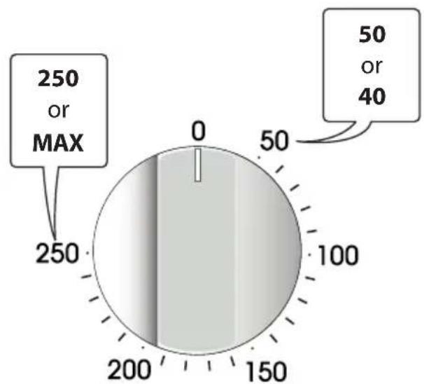
THERMOSTAT CONTROL KNOB
(fig. 4.5)
To turn on the heating elements of the oven, set function selector knob to the required position and the thermostat knob to the desired temperature.
The elements will turn on or off automatically which is determined by the thermostat.
The operation of the heating elements is signalled by a light placed on the control panel.
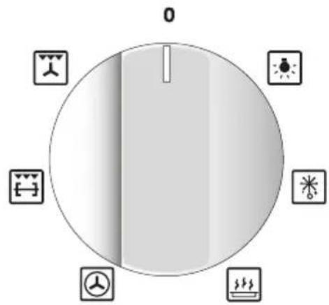
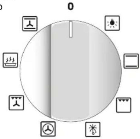
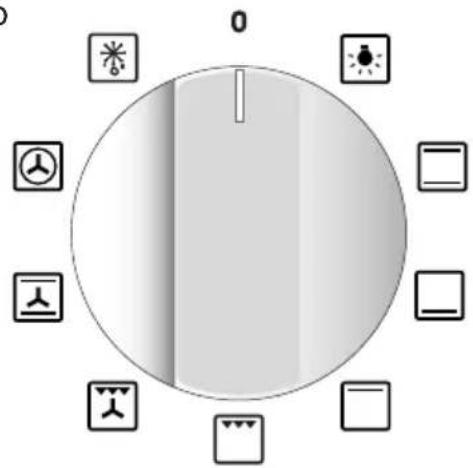
FUNCTION SELECTOR CONTROL
KNOB (fig. 4.1a, 4.1b, ..., 4.4b)
Rotate the knob clockwise to set the oven to one of the following functions:
NOTES: The knob and symbols may vary. The symbols may be printed on the knob itself.
radar
| Value | Label | |-------|-----------| | 250 | MAX | | 50 | or | | 40 | |Fig. 4.5
| Oven functions | Fan with grill models Type 1 (without rotisserie) | Fan with grill models Type 2 (with rotisserie) | Plurifunction models Type 1 (without rotisserie) | Plurifunction models Type 2 (with rotisserie) | Multifunction models Type 1 (without rotisserie) | Multifunction models Type 2 (with rotisserie) | Multifunction models Type 3 (without rotisserie) | Multifunction models Type 4 (with rotisserie) |
| √ | √ | √ | √ | √ | √ | √ | √ | |
| √ | √ | √ | √ | √ | √ | |||
| √ | √ | √ | √ | |||||
| √ | √ | √ | √ | |||||
| √ | √ | √ | √ | |||||
| √ | (1) | √ | (1) | √ | (1) | √ | (1) | |
| √ | √ | √ | √ | √ | √ | √ | √ | |
| √ | √ | √ | √ | √ | √ | |||
| √ | √ | √ | √ | √ | √ | |||
| √ | √ | √ | √ | √ | ||||
| √ | √ | √ | √ | |||||
| √ | √ | √ | √ | √ | √ | √ | √ | |
| √ | √ |
(1) Function without using the rotisserie.
NOTE: DEPENDING ON YOUR MODEL, YOUR OVEN MAY ONLY HAVE SOME OF THESE FUNCTIONS

OVEN LIGHT
By turning the function selector knob to this setting, the oven light will illuminate in the oven cavity.
The oven light will operate on all selected functions.

TRADITIONAL CONVECTION COOKING
The upper and lower heating elements are switched on.
The heat is diffused by natural convection and the temperature must be regulated between 40/50°C and the maximum position with the thermostat knob.
It is necessary to preheat the oven before introducing the foods to be cooked.
Recommended for:
For foods which require the same cooking temperature both internally and externally, i.e. roasts, spare ribs, bread, meringue, etc.

LOWER HEATING ELEMENT
In this position only the lower heating element is switched on.
Heat is distributed by natural convection. The temperature must be regulated between 40/50°C and 200°C maximum.
Recommended for:
To complete cooking of dishes that require higher temperature at the bottom.

UPPER HEATING ELEMENT
In this position only the upper heating element is switched on.
Heat is distributed by natural convection.
The temperature must be regulated between 40/50°C and the maximum position with the thermostat knob.
Recommended for:
To complete cooking of dishes that require higher temperature at the top.


TRADITIONAL GRILLING
The infrared heating element is switched on. The heat is diffused by radiation.
Use with the oven door closed and the thermostat knob must be regulated between 40/50°C and 225°C maximum with the thermostat knob.
For correct use see chapter "USE OF THE GRILL".
Some models only: In the 🔒 position the rotisserie motor come on for cooking with the rotisserie. For correct use see chapters "USE OF THE GRILL" and "USE OF THE ROTISSERIE".
Recommended for:
Intense grilling action for cooking with the broiler; browning, crisping, "au gratin", toasting, etc.

VENTILATED GRILL COOKING
The infrared heating element and the fan motor are switched on.
The heat is mainly diffused by radiation and the fan then distributes it throughout the oven.
Use with the oven door closed and the thermostat knob must be regulated between 40/50°C and 200°C maximum with the thermostat knob.
It is necessary to preheat the oven for about 5 minutes.
For correct use see chapter "GRILLING AND AU GRATIN".
Recommended for:
For grill cooking when a fast outside browning is necessary to keep the juices in, i. e. veal steak, steak, hamburger, chicken etc.

CONVECTION COOKING WITH VENTILATION
The upper and lower heating elements and the fan motor are switched on.
The heat coming from the top and bottom is diffused by forced convection.
The temperature must be regulated between 40/50°C and the maximum position with the thermostat knob.
Recommended for:
For foods of large volume and quantity which require the same internal and external degree of cooking; for ex: pizza, rolled roasts, turkey, legs, cakes, etc.

HOT AIR COOKING
The circular heating element and the fan motor are switched on.
The heat is diffused by forced convection and the temperature must be regulated between 40/50°C and the maximum position with the thermostat knob.
It is not necessary to preheat the oven.
Recommended for:
For foods that must be well done on the outside and tender or rare on the inside, i. e. steak, lasagna, lamb, roast beef, whole fish, etc.

MAINTAINING TEMPERATURE AFTER COOKING OR SLOWLY HEATING FOODS
The circular heating element and the fan motor are switched on.
The heat is diffused by forced convection and the temperature must be regulated between 40/50°C and 140°C with the thermostat knob.
Recommended for:
To keep foods hot after cooking.
To slowly heat already cooked foods.

DEFROSTING FROZEN FOODS OR SLOW HEATING AND KEEPING FOOD WARM
With the thermostat knob on “●” only the oven fan is on.
The defrosting is done by simple ventilation without heat.
Recommended for:
To rapidly defrost frozen foods; 1 kilogram requires about one hour.
The defrosting times vary according to the quantity and type of foods to be defrosted.
SLOW HEATING AND KEEPING FOOD WARM
The temperature must be regulated between 60^ C and 80^ C with the thermostat knob. The upper and lower heating elements and the fan turn on.
The heat coming from the top and bottom is diffused by forced convection.
Recommended for:
To keep foods hot after cooking. To slowly heat already cooked foods.

UPPER HEATING ELEMENT WITH VENTILATION
The upper heating element and the fan motor are switched on.
The heat coming from the top is diffused by forced convection.
The temperature must be regulated between 40/50°C and the maximum position with the thermostat knob.
Recommended for:
To keep foods hot after cooking.
To slowly heat already cooked foods.
NOTE: DEPENDING ON YOUR MODEL, YOUR OVEN MAY ONLY HAVE SOME OF THESE FUNCTIONS
STERILIZATION
Sterilization of foods to be conserved, in full and hermetically sealed jars, is done in the following way:


a. Set the switch to position
b. Set the thermostat knob to position 185^ C and preheat the oven.
c. Fill the grill pan with hot water.
d. Set the jars into the grill pan making sure they do not touch each other and the door and set the thermostat knob to position 135°C.
When sterilization has begun, that is, when the contents of the jars start to bubble, turn off the oven and let cool.
COOKING DIFFERENT DISHES AT THE SAME TIME
With the function selector in position 📄, the ventilated oven allows you to cook different types of food at the same time.
Fish, cakes and meat can be cooked together without the smells and flavours mixing.
The only precautions required are the following:
- The cooking temperatures must be as close as possible with a maximum difference of 20 - 25°C between the different foods.
- Different dishes must be placed in the oven at different times according to the cooking time required for each one. This type of cooking obviously provides a considerable saving on time and energy.
REGENERATION
Set the switch to position ☐ and the thermostat knob to position 150°C.
Bread becomes fragrant again if wet with a few drops of water and put into the oven for about 10 minutes.
ROASTING
To obtain classical roasting, it is necessary to remember:
- that it is advisable to maintain a temperature between 180 and 200^ .
- that the cooking time depends on the quantity and the type of foods.
USE OF THE GRILL
Leave to warm up for approximately 5 minutes with the door closed.
Place the food inside positioning the rack as near as possible to the grill.
Insert the drip pan under the rack to collect the cooking juices.
GRILLING AND "AU GRATIN"
Grilling may be done by selecting grill+fan setting 📁 with the function selector knob, because the hot air completely envelops the food that is to be cooked.
Set the thermostat knob and after having preheated the oven, simply place the food on the grid.
Close the door and let the oven operate until grilling is done.
Adding a few dabs of butter before the end of the cooking time gives the golden “au gratin” effect.
Always grill with the oven door closed.
It is recommended that you do not grill for longer than 30 minutes at anyone time.
Attention: The oven door becomes very hot during operation. Keep children away.
The external parts of the oven become hot during operation. Keep children well out of reach.
ROTISSERIE (MODELS WITH ROTISSERIE ONLY)
This is used for spit roasting under the grill and comprises:
- an electric motor fitted to the rear of the oven;
- a stainless steel skewer provided with slide-out heatless handgrip and two sets of adjustable forks;
- a skewer support to be fitted in the middle runner.
The rotisserie motor is operated by a switch knob (fig. 4.1b, 4.2b, 4.3b, 4.4b - or 4.6 position).

natural_image
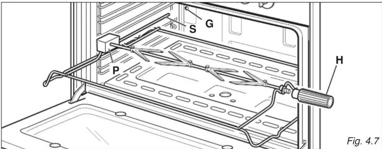
Diagram of a circular object with internal structure and a small inset showing a leaf symbol, labeled Fig. 4.6 (no text or symbols on the object itself)USE OF THE ROTISSERIE
- Insert the tray into the lowest rack holders of the oven and insert the rod support into the intermediate rack holders.
- Put the meat to be cooked onto the rod, being careful to secure it in the center with the special forks.
- Important! Take care, the forks are sharp!
- Insert the rod into the side gear opening "P" (fig. 4.7)
- Remove the grip "H" by turning it to the left.
- Insert completely the rotisserie support; the shaft "S" must be inserted in the spit motor collar "G".
- Switch on the electric grill and the rotisserie. The rotation direction of the rotisserie can be either clockwise or counter-clockwise.
Attention: the oven door becomes very hot during operation. Keep children away.
It is recommended that you do not grill for longer than 30 minutes at any one time.
text_image
S G P H Fig. 4.7
ALARM, ELECTRIC OR ELECTRONIC CLOCK
NOTES: The knob and symbols may vary. The symbols may be printed on the knob itself.
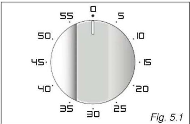
MODELS WITH 60 MINUTES ALARM
(fig. 5.1)
The minute counter is a timed acoustic warning device which can be set for a maximum of 60 minutes.
The knob must be rotated clockwise as far as the 60 minute position and then set to the required time by rotating it anticlockwise.
MODELS WITH 120 MINUTES ALARM (fig. 5.2)
The minute counter is a timed acoustic warning device which can be set for a maximum of 120 minutes.
The knob must be rotated clockwise as far as the 120 minute position and then set to the required time by rotating it anticlockwise.
ATTENTION - MOST IMPORTANT: This is only a mechanical timer that DOES NOT switch off the oven or grill. REMEMBER TO TURN OFF THE OVEN OR GRILL MANUALLY.
MODELS WITH 120 MINUTES CUT-OFF TIMER (fig. 5.3a, 5.3b)
The timer runs the oven for a preset time.
1. Starting up.
After setting the function selector and thermostat to the required mode and temperature, rotate the timer knob clockwise until you reach the required cooking time (max 120 minutes) (fig. 5.3a).
Once this time has elapsed, the timer will return to the "0" position and the oven will automatically switch off.
2. Manual position.
If the cooking time is longer than two hours or if you wish to use the oven manually, switching it off as required, the knob must be turned counterclockwise to position 📋 (fig. 5.3b).
radar
| Angle (°) | Value | | --------- | ----- | | 0 | 0 | | 5 | 5 | | 10 | 10 | | 15 | 15 | | 20 | 20 | | 25 | 25 | | 30 | 30 | | 35 | 35 | | 40 | 40 | | 45 | 45 | | 50 | 50 | | 55 | 55 |
radar
| Angle | Value | |-------|-------| | 0 | 0 | | 10 | 10 | | 20 | 20 | | 30 | 30 | | 40 | 40 | | 50 | 50 | | 60 | 60 | | 70 | 70 | | 80 | 80 | | 90 | 90 | | 100 | 100 | | 110 | 110 |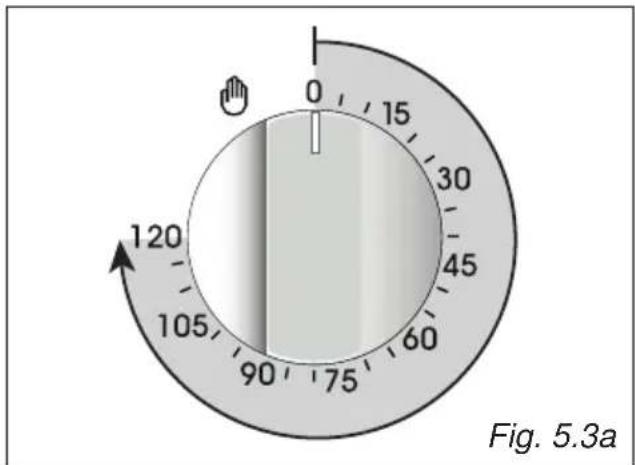
text_image
0 15 30 45 60 75 90 105 120 Fig. 5.3a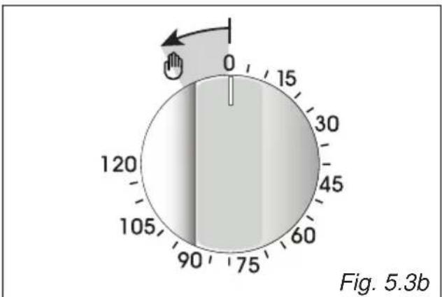
text_image
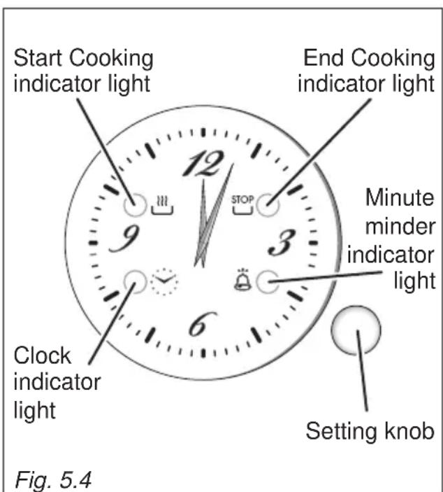
0 15 120 105 90 75 60 45 30 0 Fig. 5.3bMODELS WITH ELECTRIC CLOCK/PROGRAMMER (START-END COOKING) (fig. 5.4)
The electric clock/programmer is a device which groups the following functions:
• 12-hour analog clock;
• minute minder (max 3 hours);
• automatic cooking (* see note below);
- acoustic signal (beep) which is activated each time the “setting knob” is pressed or at the end of the minute minder function or automatic cooking program.
(*) The maximum programmable time (MPT) depends from the set start cooking time.
MPT = 15 hours - difference of hours between the set start cooking time and the time of day (eg. time of day = 08:00, set start cooking time = 11:00; MPT = 15 - 3 = 12 hours).
text_image
Start Cooking indicator light End Cooking indicator light Minute minder indicator light Clock indicator light Setting knob Fig. 5.4ELECTRIC CLOCK
Upon immediate connection of the appliance or after a blackout, the “clock indicator light” is flashing. This indicates that it is recommended to check if the time of the day is correct.
- If the time of the day is correct keep the “setting knob” pressed until the “clock indicator light” goes out.
- To set the time of the day press the “setting knob” briefly (repeatedly) until the “clock indicator light” is flashing. Then turn the “setting knob” (to the right or left) to set the time of the day.
At the end of the time adjustment, keep the “setting knob” pressed for confirmation until the “clock indicator light” goes out.
MINUTE MINDER
The minute minder function consists only of a buzzer which is automatically activated at the end of the set time (max 3 hours).
Important : It is not possible to use the minute minder function if an automatic cooking has been set.
To set the minute minder press the “setting knob” briefly (one or more times) until the “minute minder indicator light” is flashing.
Then turn the “setting knob” (to the right or left) to set the time.
At the end of the adjustment (within 10 seconds), keep the “setting knob” pressed for confirmation until the “minute minder indicator light” changes from flashing to steadily lit.
Then the countdown starts immediately.
At the end of the time, the “minute minder indicator light” changes from steadily lit to flashing and a buzzer (beep) sounds for one minute.
Press the “setting knob” briefly to stop the buzzer and to turn off the flashing “minute minder indicator light”.
During the minute minder program it is possible, at any time, to display the set time by pressing the “setting knob” briefly (one or more times) until the “minute minder indicator light” is flashing.
To cancel the program before completion, keep the “setting knob” pressed for about 3 seconds until the “minute minder indicator light” goes out; the minute minder function will be cancelled.
ATTENTION - MOST IMPORTANT: This is only an alarm that DOES NOT switch off the oven or grill. REMEMBER TO TURN OFF THE OVEN OR GRILL MANUALLY.
AUTOMATIC COOKING
Use automatic cooking to automatically turn the oven on, cook, and then turn the oven off.
- Check the clock shows the correct time.
- Select the function and temperature (function and temperature knobs). The oven will come on.
- Press the "setting knob" briefly (one or more times) until the "Start Cooking indicator light" is flashing.
Then turn the “setting knob” (to the right or left) to set the start cooking time (not less than 2 minutes and max 12 hours from the current time of the day).
At the end of the adjustment (within 10 seconds), keep the “setting knob” pressed for confirmation until the “Start Cooking indicator light” changes from flashing to steadily lit. - Decide how long the food will take to cook, allowing time for preheating if necessary.
Press the “setting knob” briefly (one or more times) until the “End Cooking indicator light” is flashing.
Then turn the “setting knob” (to the right or left) to set the end cooking time (at least 2 minutes from the set start cooking time).
At the end of the adjustment (within 10 seconds), keep the “setting knob” pressed for confirmation until the “End Cooking indicator light” changes from flashing to steadily lit.
If there is time to wait before cooking starts, the oven will switch off but is now set for automatic cooking.
If you are already at home to turn the oven on and only want the oven to turn off automatically, start cooking as normal, then follow step 4 to set a time to stop the oven.
- To see the set start cooking time, press the “setting knob” briefly (one or more times) until the “Start Cooking indicator light” is flashing.
- To see the set stop time, press the “setting knob” briefly (one or more times) until the “End Cooking indicator light” is flashing.
- To cancel the program before completion, keep the “setting knob” pressed for about 3 seconds until the “Start Cooking indicator light” and/or “End Cooking indicator light” go/goes out. REMEMBER TO TURN OFF THE OVEN OR GRILL MANUALLY.
When the stop time is reached, the oven will turn off, the “End Cooking indicator light” changes from steadily lit to flashing and a buzzer (beep) sounds for one minute.
- Press the “setting knob” briefly to stop the buzzer and to turn off the flashing “End Cooking indicator light”.
- Turn the temperature and function knobs to the off position.
Attention: After a power failure any automatic program is NOT deleted and the “clock indicator light” is flashing (this indicates that it is recommended to check if the time of the day is correct).
MODELS WITH ELECTRONIC CLOCK WITH ALARM (fig. 5.5)
The electronic clock is a device which groups the following functions:
• 24 hours clock with illuminated display;
- 99 minutes alarm.
| Description of the buttons: | ||
| A |  or otherequivalentsymbols or otherequivalentsymbols | Timer |
| B |  or otherequivalentsymbols or otherequivalentsymbols | To decrease thenumbers on thedigital display |
| C |  or otherequivalentsymbols or otherequivalentsymbols | To increase thenumbers on thedigital display |
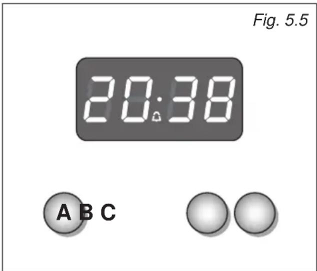
text_image
Fig. 5.5 20:38 A B CUpon immediate connection of the oven or after a blackout, three zeros will flash on the display.
To set the hour it is necessary to push the "A" button and then, within 7 seconds, the "B" or "C" button until you have set the exact hour.
An energy black-out makes the clock go to zero.
ELECTRONIC ALARM
The alarm program consists only of a buzzer which may be set for a maximum period of 99 minutes.
To set the time, push the "B" or "C" button until you obtain the desired time in the display.
Having finished the setting, the 🔒 symbol will be lit and the countdown will start immediately.
At the end of the time, an intermittent buzzer, during 7 minutes, will go off; this can be stopped by pressing the "C" button.
To stop the alarm countdown in any moment press the "B" and "C", buttons together and release the "C" button first.
SETTING THE FREQUENCY OF THE ALARM SOUND
The selection from 3 possibilities of sound can be made by pressing the "B" button.
MODELS WITH ELECTRONIC CLOCK/ END COOKING TIMER (fig. 5.6)
The electronic clock/end cooking timer is a device which groups the following functions:
• 24 hours clock with illuminated display;
- timing of oven cooking with automatic switch-off (max 99 minutes).
| Description of the buttons: | ||
| A |  or other equivalent symbols or other equivalent symbols | Timer |
| B |  or other equivalent symbols or other equivalent symbols | To decrease the numbers on the digital display |
| C |  or other equivalent symbols or other equivalent symbols | To increase the numbers on the digital display |
ELECTRONIC CLOCK
Upon immediate connection of the cooker or after a mains failure, three zeros will flash on the display.
To set the clock it is necessary to push the "A" button and then, within 7 seconds, the "B" or "C" button until you have set the correct time.
The clock will show zero after a mains failure.
Attention: When the display shows three zeros the oven cannot be switched on. The oven can be switched on when the symbol 🎨 is shown in the display.
SETTING THE FREQUENCY OF THE ALARM SOUND
The selection from 3 possibilities of sound can be made by pressing the "B" button.
COOKING WITH AUTOMATIC SWITCH-OFF
The aim of this function is to automatically stop the cooking after a preprogrammed time, for a maximum period of 99 minutes. To set the cooking time, push the "B" or "C" button until you obtain the desired time in the display. The symbol AUTO (or A) will be shown in the display. Then set the oven selector and thermostat knobs according to the cooking function and temperature required.
The oven will immediately start to operate and will work for the preprogrammed time. The display shows the count down.
Clock time can be displayed by pressing the "A" button. Once the time has elasped, the oven will switch off automatically, the symbol AUTO (or A) will go off and an intermittent buzzer, lasting 7 minutes, will start; this can be stopped by pressing the "C" button.
Important: Before the buzzer is stopped switch off the oven manually.
To cancel the cooking program at any time press the "B" and "C" buttons together and release the "C" button first.
ELECTRONIC ALARM
The electronic clock can be used as an alarm only for a maximum period of 99 minutes. To set the alarm, push the "B" or "C" button until you obtain the desired time in the display. Once the time has elapsed, an intermittent buzzer, lasting 7 minutes, will start; this can be stopped by pressing the "C" button.
Attention: If the oven is switched on when the buzzer starts, it will be automatically switched off. For it to operate furtherly you have to stop the buzzer by pressing the "C" button.
Then remember to switch the oven off manually.

text_image
Symbol AUTO or A Fig. 5.6 A 18:25 A B CMODELS WITH ELECTRONIC CLOCK/PROGRAMMER (START-END COOKING) (figs. 5.7, ..., 5.14)
The electronic clock/programmer is a device which groups together the following functions:
• 24 hours clock with illuminated display;
- timer (up to 23 hours and 59 minutes);
• program for automatic oven cooking;
• program for semi-automatic oven cooking.
| Description of the illuminated symbols: | |
| AUTO flashing | Programmer in automatic or semi-automatic position but not programmed. |
| AUTO illuminated | Programmer in automatic or semi-automatic position with program inserted. |
| Oven set for manual cooking or automatic/semi-automatic cooking taking place. | |
| Timer in operation. | |
| and AUTO flashing | Program error.(The time of day lies between the calculated cooking start and end time). |
Note: Select a function by the respective button and, in 5 seconds, set the required time with the "E" / "F" buttons ("one-hand" operation). After a power cut the display resets to zero and cancels the set programs.
| Description of the buttons: | ||
| A | or other equivalent symbols | Timer |
| B | or other equivalent symbols | Cooking time |
| C | or other equivalent symbols | End of cooking time |
| D | or other equivalent symbols | Manual position, cancellation of the inserted cooking program and set the time of the day |
| E | or other equivalent symbols | To decrease the numbers on the digital display |
| F | or other equivalent symbols | To increase the numbers on the digital display |

text_image
20:38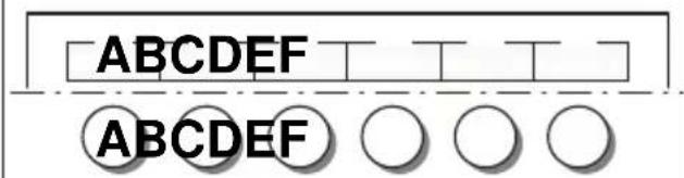
text_image
A B C D E F A B C D E F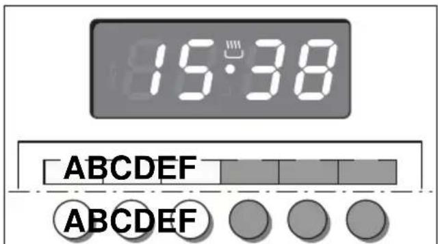
text_image
15:38 ABCDEF ABCDEFFig. 5.8 Fig. 5.7
ELECTRONIC CLOCK (fig. 5.8)
The programmer is equipped with an electronic clock with illuminated numbers which indicates hours and minutes.
Upon immediate connection of the oven or after a power cut, three zeros will flash on the programmer display.
To set the correct time of day it is necessary to push the "D" button and then the "E" or "F" button until you have set the correct time (fig. 5.8).
In another way push simultaneously the "B" / "C" two buttons and at the same time push the "E" or "F" button.
Note: If the clock is reset it deletes any previously set programs
NORMAL COOKING WITHOUT THE USE OF THE PROGRAMMER
To manually use the oven, without the aid of the programmer, it is necessary to cancel the flashing AUTO by pushing the "D" button (AUTO will be switched off and the symbol 🎨 will illuminate - fig. 5.9).
Attention: If the AUTO is illuminated (which means a cooking program has already been inserted), by pushing the button "D" you cancel the program and return to manual operation.
If the oven is switched on, you must switch it off manually.
ELECTRONIC TIMER
The timer program consists only of a buzzer which may be set for a maximum period of 23 hours and 59 minutes.
If the AUTO symbol is flashing push the "D" button.
To set the time, push the "A" button and the "E" or "F" until you obtain the desired time in the display (fig. 5.10).
Having finished the setting, the clock hour will appear on the panel and the ⏻ symbol will be illuminated.
The countdown will start immediately and may be seen at any moment on the panel by simply pressing the button "A".
At the end of the time, the 🔒 symbol will disappear and the buzzer will sound for some minutes or until a button is pressed (not the “E” / “F” buttons).
After a short time the display will revert back to the time of day.
SETTING THE FREQUENCY OF THE AUDIBLE SIGNAL
The buzzer has 3 different tones and can be changed by pressing the “E” button, but only when the time of day is displayed

text_image
18:25 ABCDEF ABCDEF Fig. 5.9
text_image
8:3:00 ABCDEF ABCDEF Fig. 5.10To cook food automatically in the oven, it is necessary to:
- Set the length of the cooking period.
- Set the end of the cooking time.
- Set the temperature and the oven cooking program.
These operations are done in the following way:
- Set the length of the cooking period by pushing the "B" button and the "F" button to increase or "E" to decrease if you have passed the desired time (fig. 5.11). The AUTO and the 🔊 symbol will illuminate.
- Set the end of the cooking time by pressing the "C" button (the cooking time already added to the clock time will appear) and the "F" button (fig. 5.12); if you pass the desired time you may get back by pushing the "E" button.
After this setting, the 🎨 symbol will disappear. If after this setting, the AUTO flashes on the display and a buzzer sounds, it means there was an error in the programming, that is that the cooking cycle has been superimposed on the clock. In this case, modify the end of cooking time or the cooking period itself by following again the above mentioned instructions.
- Set the temperature and the cooking function by using the switch and thermostat knobs of the oven (see specific chapters).
Now the oven is programmed and everything will work automatically, that is the oven will turn on at the right moment to end the cooking at the established hour.
During cooking, the ⏚ symbol remains illuminated.
By pushing the "B" button you can see the time that remains until the end of cooking.
The cooking program may be cancelled at any time by pushing "D".
At the end of the cooking time the oven will turn off automatically, the 🔊 symbol will turn off, AUTO will flash and a buzzer will sound, which can be turned off by pushing any of the buttons except the “E” / “F” buttons.
Turn the switch and thermostat knobs to zero and set the programmer onto "manual" by pressing the "D" button.
Attention: After a power cut the clock resets to zero and cancels the set programs.
After a power cut, three zeros will flash on the display.
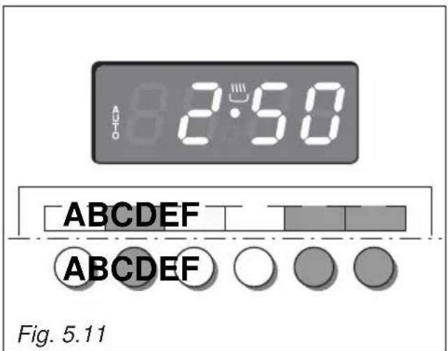
text_image
2:50 ABCDEFG ABCDEFG Fig. 5.11
text_image
12:55 ABCDEFG ABCDEFG Fig. 5.12SEMI-AUTOMATIC COOKING
This is used to automatically switch off the oven after the desired cooking time has elapsed.
There are two ways to set your oven:
- Set the length of the cooking time by pushing the "B" button and the "F" button to advance, or "E" to go backwards if you have passed the desired time (fig. 5.13).
or
- Set the end of the cooking time by pushing the "C" button and the "F" button to advance, or "E" to go backwards if you have passed the desired time (fig. 5.14).
AUTO and the 🔊 symbol will be on.
Then set the temperature and the cooking function using the oven switch and thermostat knobs (see specific chapters).
The oven is switched on and it will be switched off automatically at the end of the desired time.
During cooking, the 🔊 symbol remains on and by pressing the button "B" you can see the time that remains till the end of the cooking.
The cooking program may be cancelled at any time by pushing "D".
At the end of the cooking time the oven will turn off automatically, the symbol will turn off, AUTO will flash and a buzzer will sound, which can be turned off by pushing any of the buttons except the "E" / "F" buttons.
Turn the switch and thermostat knobs to zero and set the programmer onto "manual" by pressing the "D" button.
Attention: After a power cut the clock resets to zero and cancels the set programs.
After a power cut, three zeros will flash on the display.
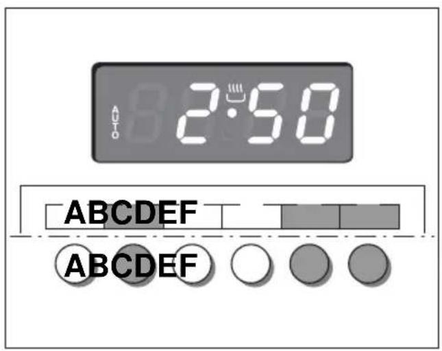
text_image
2:50 A ABCDEF ABCDEF
text_image
12:56 ABCDEF ABCDEF Fig. 5.14Fig. 5.13| Keys: | ||
| A and C | ⊕ and ⊖ or ▲ and ▼ or other equivalent symbols | Touched simultaneously (for more than 2 seconds):• setting the clock;• setting the timer volume (by touching once, along with the “B” key);• to cancel automatic cooking at any time. |
| B | MODE or other equivalent wording / symbol | Function selection (touched for more than 2 seconds):• setting the clock (only after first connection or after a power failure);• timer;• automatic cooking “dur” (duration) - how long the food will take to cook (by touching the “B” key again);• automatic cooking “End” - the time you would like the oven turns off (by touching the “B” key two more times). |
| A | ⊖ or ▼ or other equivalent symbols | Decreases the number shown on the display |
| C | ⊕ or ▲ or other equivalent symbols | Increases the number shown on the display |

text_image
AUTO 20:38ABC


Fig. 5.15
| Illuminated symbols: | ||
| AUTO flashing | Automatic cooking completed, oven in automatic position but not set | |
| AUTO | steady illumination | Oven set for automatic cooking, cooking still not taking place |
| flashing | Timer being set | |
| steady illumination | Timer in operation | |
| steady illumination | Oven set for manual cooking | |
| and AUTO | AUTO flashing | Automatic cooking being set |
| and AUTO | steady illumination | Oven set for automatic cooking, cooking taking place |
"TOUCH-CONTROL" KEYS
The “touch-control” keys shall be operated by the fingers (just by touching the key). When using touch controls it is best to use the ball of your finger rather than the tip.
The keys are automatically deactivated:
- 8 seconds after the last selection; the deactivation is indicated by an acoustic signal ("beep").
To reactivate just touch the “B” key or the “A” and “C” keys (simultaneously) for more than 2 seconds.
SETTING THE CLOCK
When first connected, or after a power failure, the digits and "AUTO" will shown on the display.
Important: The oven does not operate, in manual cooking, without first having set the clock.
To set the clock, touch the "B" key, for more than 2 seconds, and then the "A" or "C" keys. To set the clock, with the appliance already connected, touch the "A" and "C" keys simultaneously (for more than 2 seconds), then "A" or "C" keys.
Important:
- changing the time will delete any automatic program;
- after setting the clock, the oven starts to operate in the selected function (manual cooking). The “ 🔊 ” symbol is steady illuminated.
USING THE TIMER
You can use the timer at any time, even when the oven is not in use.
The timer does not turn the oven off.
The timer can be set for up to 23 hours and 59 minutes.
- To set the timer, touch the “B” key for more than 2 seconds (the “△” symbol flashes), than the “C” or “A” keys.
- After about 8 seconds an acoustic signal ("beep") will sound confirming the regulation ("△" symbol steady illuminated).
- To check the remaining time touch the “B” key for more than 2 seconds. If the remaining time is more than a minute the display will show hours and minutes; if less than a minute the display will show seconds.
- When the time is up, the timer will beep. Touch the “B” key, for more then 2 seconds, to turn it off; or press the “A” or “C” key to stop the beep and than the “B” key, for more than 2 seconds, to deactivate the “△” symbol flashing on the display.
- Turn off the oven manually (function and thermostat knobs in the off position) if the manual cooking has been completed.
SETTING THE TIMER VOLUME
You can select from three volume levels.
- Touch the “A” and “C” keys simultaneously for more than 2 seconds.
- Touch the "B" key; you can read on the display the current timer volume ("ton1", "ton2" or "ton3").
- Touch the "A" key to listen or change the timer volume.
- Timer volume activated: the last displayed.
- After about 8 seconds an acoustic signal ("beep") will sound confirming the volume setting; then the time of day will be displayed.
AUTOMATIC COOKING
Use automatic cooking to automatically turn the oven on, cook, and then turn the oven off.
- Check the clock shows the correct time.
- Select the function and temperature (function and temperature knobs). The oven will come on.
-
Decide how long the food will take to cook, allowing time for preheating if necessary.
-
Touch the "B" key for more than 2 seconds and then touch again; "dur" will show (duration). Using the "C" and "A" keys, set the cooking time.
-
Decide the time you would like the oven to turn off; touch the "B" key for more than 2 seconds and then touch it two times again; "End" will show. Using the "C" and "A" keys, set the stop time.
Note: while "dur" is displayed you can change to "End" just by touching one time the "B" key (within 8 seconds from the last selection).
If there is time to wait before cooking starts, the current time of day and "AUTO" will show in the clock display. The oven will switch off but is now set for automatic cooking.
If you are already at home to turn the oven on and only want the oven to turn off automatically, start cooking as normal, then follow step 4 or step 5 to set a time to stop the oven.
When automatic cooking starts, “ 🚗 ” will be displayed and the oven will turn on.
• To see the remaining cook time, follow step 4 up to display “dur” (duration).
• To see the set stop time, follow step 5 up to display "End".
- To cancel automatic cooking at any time, touch the “A” and “C” keys simultaneously (for more than 2 seconds) and turn the temperature and function knobs to the off position.
When the stop time is reached, the oven will turn off, the timer will beep and "AUTO" will flash:
- Touch any key to stop the beeping.
- Touch the “B” key, for more than 2 seconds, to return the oven to the manual mode (“ ” symbol steady illuminated on the display).
- Turn the temperature and function knobs to the off position.
Attention: After a power failure any automatic program is deleted. Turn off the oven manually.
MODELS WITH ELECTRONIC CLOCK/PROGRAMMER "Touch-Control" (START-END COOKING) (fig. 5.16)
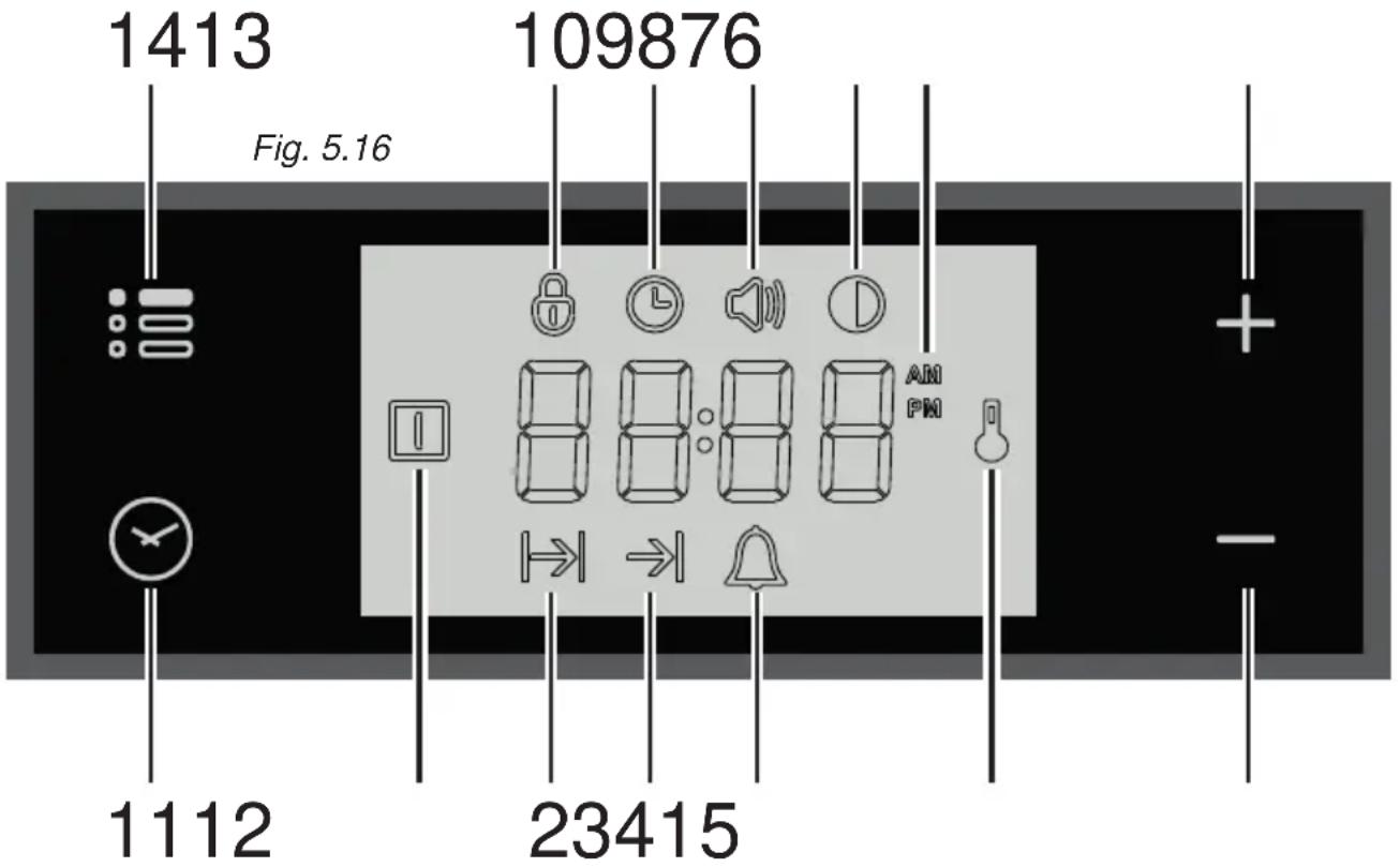
text_image
1413 Fig. 5.16 109876 1112 23415Description of display symbols:
- Oven on
- Cooking time
- End of cooking time
- Timer
- Oven temperature
- AM/PM time format
- Screen brightness
- Acoustic signal volume
- Time of day setting
- Programmer 'touch' control panel key lock
Description of the ‘touch control’ panel symbols:
- Program selection
- Digit backward setting for all functions
- Digit forward setting for all functions
- Menu selection
IMPORTANT NOTE: When using the timer and during a semi-automatic or automatic cooking, the countdown of the function with less time remaining prevails on the display.
ATTENTION - MOST IMPORTANT:
ELECTRONIC PROGRAMMER DISPLAY CLEANING
Strictly follow the information indicated in the chapter "CLEANING AND MAINTENANCE".
"TOUCH-CONTROL" KEYS
The “touch-control” keys shall be operated by the fingers (just by touching the key). When using touch controls it is best to use the ball of your finger rather than the tip. Program and menu selection: after starting the procedure, the selection is automatically deactivated after approx. 5 seconds from the last touch on the display.
SETTING THE CLOCK
When connecting for the first time, or after a power failure, the word "OFF" flashes on the display and the " ℓ " symbol is lit. Adjust the time touching the "+" or "-" key.
Important: The oven does not operate, in manual cooking, without first having set the clock.
To change the time with the appliance already installed, touch the "☐" key for more than 2 seconds, then touch it again until the "☐" symbol flashes. Then adjust the time, within 5 seconds, using the "+" or "—".
Important: It is not possible to adjust the clock if a cooking program is in progress.
USING THE TIMER
You can use the timer at any time, even when the oven is not in use.
ATTENTION - MOST IMPORTANT: This is only an alarm that DOES NOT switch off the oven or grill.
REMEMBER TO TURN OFF THE OVEN/GRILL MANUALLY.
The timer can be set for a maximum time of 23 hours and 59 minutes.
-
To set the timer, with the appliance already connected, touch the " 🔍" key (several times) until the " 🔍" symbol flashes on the display. Set the time (increase in minutes) within 5 seconds using the "+" or "—". Key. At the end of the adjustment the display shows the countdown.
-
At the end of the count, the timer starts beeping and the “ 🔊 ”symbol flashes on the display. Touch any key to turn off the acoustic signal that would otherwise stop after 7 minutes.
-
Turn the oven off manually (switch and thermostat knobs in the off position) if you do not wish to continue with manual cooking.
To reset the timer in operation at any time:
1A. Only timer function active (no semi-automatic or automatic cooking in progress): touch the " ” key for 3 seconds..
1B. With semi-automatic or automatic cooking in progress: touch the key several times " 🔥 " until the " 🔥 symbol flashes on the display. Then touch the "—" key within 5 seconds until " 00:00 " appears on the display.
- The time of day is shown on the display.
SEMI-AUTOMATIC COOKING
This is used to automatically switch off the oven after the desired cooking time has elapsed. Check the clock shows the correct time.
The semi-automatic cooking program can be set for a maximum period of 10 hours.
- Select the function and temperature (function and temperature knobs). The oven will come on.
- Touch the "☐" key until the "☐" symbol flashes on the display. Set the cooking time (increase in minutes - consider the preheating time, if necessary) within 5 seconds using the "+" or "—". At the end of the adjustment the display shows the countdown.
- At the end of the count the oven turns off, the timer starts beeping, the " " symbol flashes and the word "End" appears on the display.
- Turn the temperature and function knobs to the off position.
- Touch the " ☑" key to deactivate the acoustic signal (which otherwise will stop after 7 minutes) and to return the programmer to manual mode (the time is shown on the display). If instead the acoustic signal is deactivated with one of the other keys, after deactivation also touch the " ☑" key to return the programmer to manual mode (the time is shown on the display).
To cancel the semi-automatic cooking program at any time:
1A. Only semi-automatic cooking function active (no timer in use): touch the " 🔊 " key for 3 seconds, the " | symbol and the word "End" (fine) are shown on the display.
1B. With active timer: touch the "☐" key several times until the "☐" symbol flashes. Then touch the “—” key within 5 seconds until 00:00 " appears on the display, replaced after a few seconds by the "☐" symbol and the word "End".
- Touch the "☐" key again to return the programmer to manual mode (the time of day is shown on the display). If cooking is finished turn the temperature and function knobs to the off position, otherwise continue cooking and then remember to turn the oven off manually.
AUTOMATIC COOKING
Use automatic cooking to automatically turn the oven on, cook, and then turn the oven off. Check the clock shows the correct time.
- Select the function and temperature (function and temperature knobs). The oven will come on.
- Decide the cooking time considering the preheating time, if necessary, and set it as described above in the “SEMI-AUTOMATIC COOKING” chapter.
- Touch the "☐" key several times until the "⇒" symbol appears on the display. Then set the time at which you want the oven to turn off, touching the "+" or "-" key.
- If the cooking is not started immediately, the display shows the current time of day and the "12" and " " symbols. The oven turns off but now it is set for automatic operation.
- To check the cooking time, touch the "√" key once, the "|→|" symbol flashes.
- To check the turn-off time, touch the key ⏻ several times until the → symbol flashes.
To cancel the automatic cooking program at any time, proceed as described in the “SEMI-AUTOMATIC COOKING” chapter.
Turn the temperature and function knobs to the off position, otherwise continue cooking and then remember to turn the oven off manually.
ATTENTION - VERY IMPORTANT (AUTOMATIC OR SEMI-AUTOMATIC COOKING): If a very short power interruption occurs, the oven keeps the programming.
If the interruption is instead longer than a few tens of seconds, the automatic cooking is cancelled. In this case, turn the temperature and function knobs to the off position and restart programming if necessary.
USER PREFERENCES SETTINGS
PROGRAMMER 'TOUCH CONTROL' PANEL KEY LOCK
This function is used to prevent the accidental touch of the programmer selection keys and to avoid unintentionally activating or modifying its functions.
The key lock can be activated at any time, with a cooking in progress or with the oven off.
To lock:
- Touch the " : " key for more than 2 seconds until the " 🔒 " indicator light starts flashing. Then touch the "+" key to activate the key lock, the word "On", appears on the display, wait a few seconds until the operation is completed. When this function is active, the " 🔒 " indicator light is on.
To unlock:
- Touch the " : " key for more than 2 seconds until the " 🔒 " indicator light starts flashing. Then touch the “—” key to deactivate the key lock, the word "OFF" appears on the display, wait a few seconds until the operation is completed. When this function is not active, the " 🔒 " indicator light is off.
ACOUSTIC SIGNAL TONE SETTING
It is possible to select three sound tones.
- Touch the " : : : " key for more than 2 seconds, then touch the same key several times until the " symbol flashes.
- Touch the “+” or “—”; key; the display shows the tone set (“b-01”, “b-02” or “b-03”).
- The last tone displayed remains active.
It is possible to select three brightness levels.
- Touch the " : " key for more than 2 seconds, then touch the same key several times until the " symbol flashes.
- Touch the “+” or “—”; key; the display shows the brightness set (“d-01”, “d-02” or “d-03”).
- The last brightness displayed remains active.
TIME FORMAT
It is possible to choose the 24 hour or 12 hour clock format.
- To activate the 12 hour format, touch the “+”, key for more than 5 seconds until the "AM" or "PMSymbol is activated.
- To activate the 24 hour format, touch the “+”, key for more than 5 seconds until the "Amor" "Symbol is deactivated.
GLASS LID (SUPPLIED WITH SOME MODELS ONLY)
For cleaning purposes, the lid can be easily removed upwards once taken to the upright position.
Should the hinges slip off, replace them in their housing being careful that:
- The right housing must receive the hinge marked "D" while the left housing must receive the hinge marked "S" (fig. 6.1).
REGULATING OF THE BALANCE
Lower the lid and check the correct balance. While opened at 45^ it should hang up.
The springs of the hinges can be adjusted if necessary by turning the screws "R" clockwise (fig. 6.1).
Models with glass lid
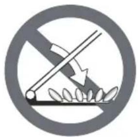
natural_image
Prohibition sign depicting a crossed-out fence with leaves, no text or symbols presentDo not shut lid when burner alight.
ATTENTION
√ Do not lower the glass lid when the gas burners are still hot or when the oven is working or still hot.
√ Do not lay on the glass lid hot pans and heavy kitchen utensils.
√ Dry off any liquid which may have spilt on the cover before opening it.
ELECTRONIC PROGRAMMER DISPLAY CLEANING (SUPPLIED WITH SOME MODELS ONLY)
Clean the programmer display using a soft cloth, warm water and neutral soap, or a soft cloth with a liquid detergent (non-abrasive). When cleaning, be careful to move the cloth in one direction only. Then wipe the display with a damp cloth and dry it with a soft cloth.
IMPORTANT: DO NOT use chlorine-based or acid-based cleaning products, abrasive products or non-neutral detergents as they may cause irreparable damage to the surface. DO NOT spray cleaning liquids directly on the programmer display.
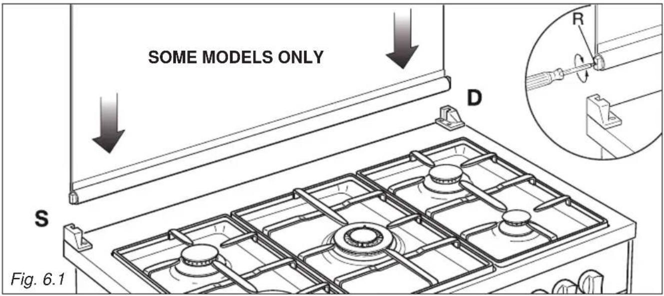
text_image
SOME MODELS ONLY D S Fig. 6.1GENERAL ADVICE
- Before you begin cleaning, you must ensure that the appliance is switched off.
- When the appliance is not being used, it is advisable to keep the gas tap closed.
- The periodical lubrication of the gas taps must be done only by specialized personnel.
- If a tap becomes stiff, do not force; contact your local After Sales Service Centre.
- It is advisable to clean when the appliance is cold and especially when cleaning the enamelled parts.
- Avoid leaving alkaline or acidic substances (lemon juice, vinegar, etc.) on the surfaces.
- Avoid using cleaning products with a chlorine or acidic base.
- Important: The use of suitable protective clothing/gloves is recommended when handling or cleaning of this appliance.
WARNING!
When correctly installed, your product meets all safety requirements laid down for this type of product category. However special care should be taken around the rear or the underneath of the appliance as these areas are not designed or intended to be touched and may contain sharp or rough edges, that may cause injury.
ENAMELLED PARTS
All the enamelled parts must be cleaned with a sponge and soapy water or other non-abrasive products.
Dry preferably with a microfibre or soft cloth.
Acidic substances like lemon juice, tomato sauce, vinegar etc. can damage the enamel if left too long.
STAINLESS STEEL, ALUMINIUM PARTS, PAINTED AND SILK-SCREEN PRINTED SURFACES
Clean using an appropriate product.
Always dry thoroughly.
IMPORTANT: these parts must be cleaned very carefully to avoid scratching and abrasion. You are advised to use a soft cloth and neutral soap.
CAUTION: Do not use abrasive substances or non-neutral detergents as these will irreparably damage the surface.
HOT PLATE
Foods burned on the hot plates must always be cleaned dry. Do not use water to avoid the forming of rust. After its use, pour a bit of oil onto the warm plate and rub with a cloth.
Important: The manufacturer declines all liability for possible damage caused by the use of unsuitable products to clean the appliance.
Attention! The appliance gets very hot, mainly around the cooking areas. It is very important that children are not left alone in the kitchen when you are cooking.
Do not use a steam cleaner because the moisture can get into the appliance thus make it unsafe.
Do not use harsh abrasive cleaners or sharp metal scrapers to clean the oven door glass or the glass lid (models with glass lid only) since they can scratch the surface, which may result in shattering of the glass.
INSIDE OF OVEN
The oven should always be cleaned after use when it has cooled down.
The cavity should be cleaned using a mild detergent solution and warm water. Suitable proprietary chemical cleaners may be used after first consulting with the manufacturers recommendations and testing a small sample of the oven cavity. Abrasive cleaning agents or scouring pads/ cloths should not be used on the cavity surface.
NOTE: The manufacturers of this appliance will accept no responsibility for damage caused by chemical or abrasive cleaning.
Let the oven cool down and pay special attention no to touch the hot heating elements inside the oven cavity.
GAS TAPS
Do not let cleaning products come into contact with the valves.
Periodic lubrication of the gas taps must be carried out by specialist personnel only. In the event of operating faults in the gas taps, call the Service Department.
BURNERS AND PAN SUPPORTS
These parts must be cleaned using a sponge and soapy water or other suitable non-abrasive products. Dry with a soft cloth.
Warning! Not dishwasher safe.
If left on the surface for a length of time, acidic substances such as lemon juice, tomato sauces and passata, vinegar and other similar products will damage the surface and dull its shine.
After cleaning, the burners and their flame spreaders must be well dried and correctly replaced.
It is very important to check that the burner flame spreader and the cap have been correctly positioned. Failure to do so can cause serious problems.
Check that the electrode "S" (figs. 6.2, 6.4, 6.5) is always clean to ensure trouble-free sparking.
Check that the probe "T" (figs. 6.2, 6.4, 6.5) next to each burner is always clean to ensure correct operation of the safety valves.
Both the probe and ignition plug must be very carefully cleaned.
Note: To avoid damage to the electric ignition do not use it when the burners are not in place.
Note: Continuous use may cause a change in the glaze around the burners and grids, corresponding to the areas exposed to the heat. This is a natural phenomenon and does not prevent the parts from working properly.
CORRECT REPLACEMENT OF THE AUXILIARY, SEMI-RAPID AND RAPID BURNERS
It is very important to check that the burner flame distributor “F” and the cap “C” has been correctly positioned (see figs. 6.2, 6.3) - failure to do so can cause serious problems.
CORRECT REPLACEMENT OF THE DOUBLE-RING COMPACT AND DUAL BURNERS
The Double-ring compact and Dual burners must be correctly positioned (see figs. 6.4, 6.5); the burner rib must be enter in their logement as shown by the arrow (see figs. 6.4, 6.5).
Then position the cap “A” and the ring “B” (figs. 6.6, 6.7).
The burner correctly positioned must not rotate (fig. 6.6).
IMPORTANT: the Dual burner flame spreader has a centring pin ("CP" in fig. 6.5).

text_image
C F S TFig. 6.2 Fig. 6.3
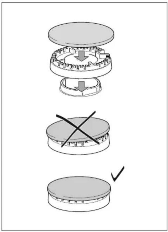
text_image
Diagram illustrating three-step assembly process: top-down, cross-section, and final step with checkmark indicating completion.
text_image
DOUBLE-RING COMPACT BURNER T S Fig. 6.4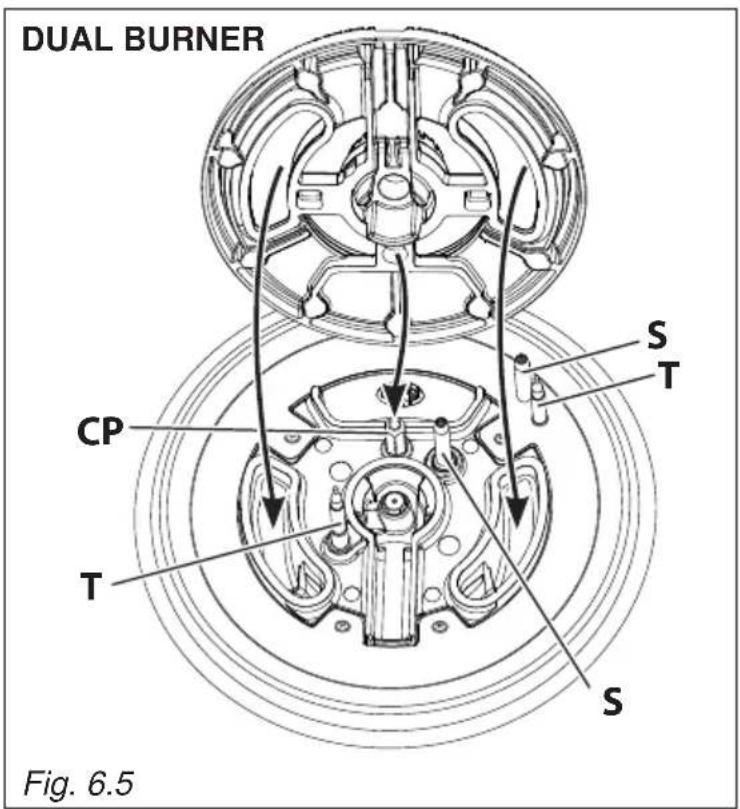
text_image
DUAL BURNER CP T S T S Fig. 6.5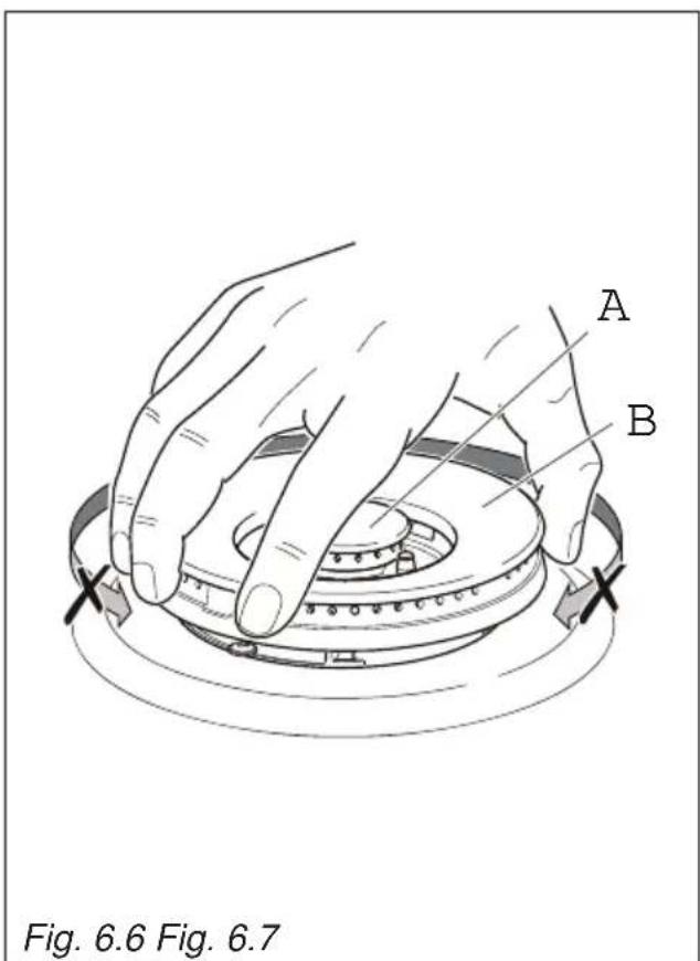
text_image
A B Fig. 6.6 Fig. 6.7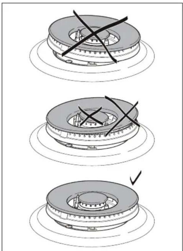
natural_image
Three-step diagram showing a mechanical component with cross marks, no text or symbols present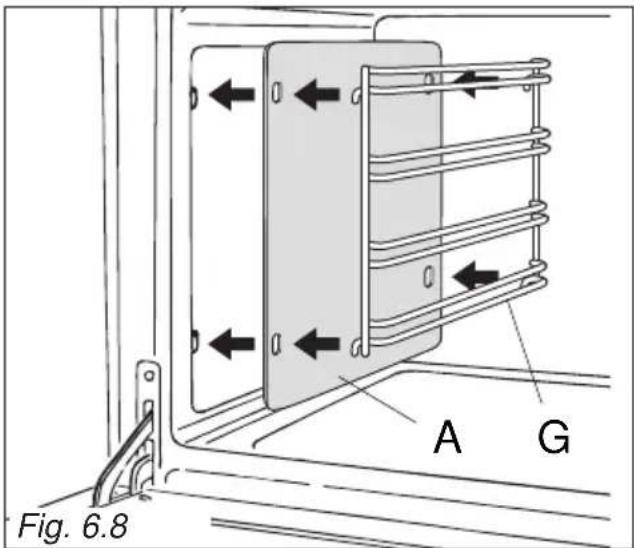
text_image
Fig. 6.8 A G
text_image
Guard rail (Some models only) Stop notch Fig. 6.9a
text_image
Guard rail (Some models only) Stop notch Fig. 6.9b Stop notchASSEMBLY AND DISMANTLING OF THE SIDE RUNNER FRAMES
- Hang up the wire racks "G" on the oven walls (fig. 6.8).
In the models with catalytic panels supplied: interpose the catalytic panels "A" (fig. 6.8).
- Slide in, on the guides, the shelf and the tray (figs. 6.9a, 6.9b).
The shelf must be fitted so that the safety catch, which stops it sliding out, faces the inside of the oven.
Some models only: The shelf must be fitted so that the safety catch, which stops it sliding out, faces the inside of the oven; the guard rail shall be at the back.
• To dismantle, operate in reverse order.
OVEN TRAY
The oven tray "L" must be inserted into the side runners (figs. 6.9a, 6.10a).
Only for the "fan assisted" models:
The oven tray must be correctly placed on its wire support then inserted into the side runners (figs. 6.9b, 610b).

natural_image
Line drawing of a refrigerator interior showing the tray and shelf (no text or symbols)
natural_image
Technical line drawing of a kitchen appliance with an inset view showing a tray and casing (no text or symbols)GREASE FILTER (some models only)
- A special screen can be fitted at the back of the oven to catch grease particles, mainly when meat is being roasted.
Slide in the grease filter on the back of the oven as in fig. 6.11.
- Clean the filter after any cooking!
The grease filter can be removed for cleaning and should be washed regularly in hot soapy water.
Always clean the filter after cooking as any solid residues on it might adversely affect the oven performance.
• Always dry the filter properly before fitting it back into the oven.
CAUTION: When baking pastry etc. this filter should be removed.

natural_image
Diagram showing two computer monitors above a circular grid-patterned area, labeled Fig. 6.11 (no text or symbols on the diagram itself)TELESCOPIC SLIDING SHELF SUPPORTS (some models only)
The telescopic sliding shelf support makes it safer and easier to insert and remove the oven shelf.
It stops when it is pulled out to the maximum position.
Important! When installing the sliding shelf support, make sure that you fit:
- The slides to the top wire of a rack. They do not fit on the lower wire.
• The slides so that they run out towards the oven door. - Both sides of each pair of shelf slides.
• Both sides on the same level.
To fix the sliding shelf supports onto the side racks:
- Fit the side runner frames into the holes on the side walls inside the oven. (fig. 6.12).
- Fit the sliding shelf supports onto the top wire of a rack and press (fig. 6.12). You will hear a click as the safety locks clip over the wire.
IMPORTANT NOTE: When cooking with the rotisserie DO NOT position the grill tray on the sliding shelf supports.

text_image
Left Right Fig. 6.12To remove the RH and LH sliding guides from the wire support:
• Find the safety locks. These are the tabs that clip over the fixing wire (arrow 1 in fig. 6.13).
• Pull the safety locks away from the fixing wire to release the sliding guide (arrow 2 in fig. 6.13).
Cleaning the sliding shelf supports:
- Wipe the supports with a damp cloth and a mild detergent only.
- Do not wash them in the dishwasher, immerse them in soapy water, or use oven cleaner on them.

text_image
1 2 1 Fig. 6.13ADVICE FOR USE AND MAINTENANCE OF SELF CLEANING PANELS
The self cleaning panels are covered with a special microporous enamel which, absorbs and removes oil and fat splashes during normal baking over 200^ C.
If, after cooking very fatty foods, the panels remain dirty, operate the oven empty on max temperature for about 30 minutes.
These panels do not require to be cleaned, however it is advised to periodically remove them from the oven (at least the side panels) and to wash them with tepid soapy water and then wipe off with a soft cloth.
DO NOT CLEAN OR WASH THEM WITH ABRASIVE PRODUCTS OR WITH PRODUCTS CONTAINING ACIDS OR ALKALIS.
The side panels are reversible and when the microporous enamel degrades, they can be turned to the other side.
REPLACING THE OVEN LAMP
WARNING: Ensure the appliance is switched oil and disconnected from the electrical power supply before replacing the lamp to avoid the possibility of electric shock.
- Let the oven cavity and the heating elements to cool down.
- Switch off the electrical supply.
- Remove the protective cover "A" (fig. 6.14).
- Replace the halogen lamp "C" with a new one suitable for high temperatures (300°C) having the following specifications: 220-240 V, 50-60Hz and same power (check watt power as stamped in the lamp itself) of the replaced lamp.

text_image
C A WRONG ✓ CORRECT Fig. 6.14IMPORTANT WARNING: Never replace the bulb with bare hands; contamination from your fingers can cause premature failure. Always use a clean cloth or gloves.
• Refit the protective cover.
Note: Oven lamp replacement is not covered by your guarantee.
STORAGE COMPARTMENT
The storage compartment is accessible through the pivoting panel (fig. 6.15).

natural_image
Technical line drawing of a mechanical assembly with mounting base and vertical supports (no text or symbols)Do not store lammable material in the oven or in the storage compartment.
REMOVING THE OVEN DOORS
The oven door can easily be removed as follows:
- Open the door to the full extent (fig. 6.16a).
- Open the lever "A" completely on the left and right hinges (fig. 6.16b).
- Hold the door as shown in fig. 6.16d.
• Gently close the door (until left and right hinge levers "A" are hooked to part "B" of the door (figs. 6.16b, 6.16c). - Withdraw the hinge hooks from their location following arrow "C" (fig. 6.16e).
- Rest the door on a soft surface.

natural_image
Technical line drawing of a mechanical clamp or bracket assembly (no text or symbols)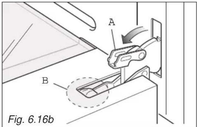
text_image
A B Fig. 6.16bImportant!
Always keep a safe distance from the door hinges, paying special attention to position of your hands.
If the door hinges are not correctly hooked, they could unhook and close suddenly and unexpectedly with risk of injury.

text_image
Warning symbol illustration showing a warning triangle with an exclamation mark and a hand holding a cross symbol.
natural_image
Technical line drawing of a mechanical component or bracket assembly (no text or symbols)
natural_image
Line drawing of hands installing or adjusting a door panel on a lift (no text or symbols)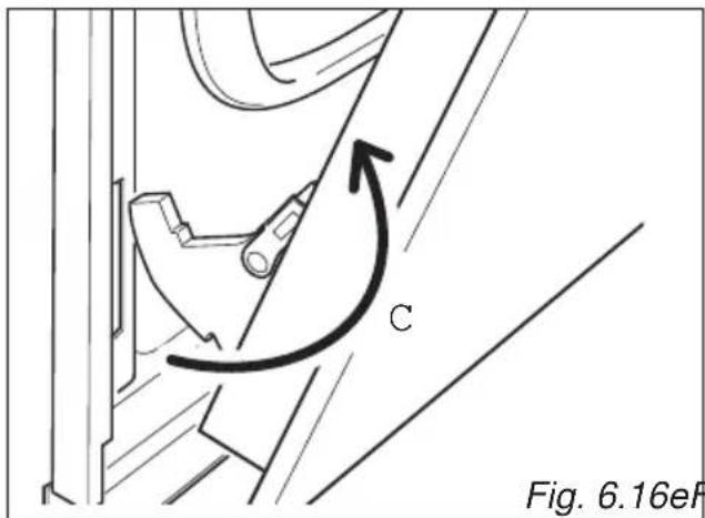
text_image
C Fig. 6.16eFFig. 6.16e Fig. 6.16
REFIT THE DOORS
- Hold the door firmly (fig. 6.17a).
- Insert the hinge tongues into the slots, making sure that the groove drops into place as shown in the figure 6.17b.
- Open the door to its full extent.
- Fully close the levers "A" on the left and right hinges, as shown in the figure 6.17c.
- Close the door and check that it is properly in place.
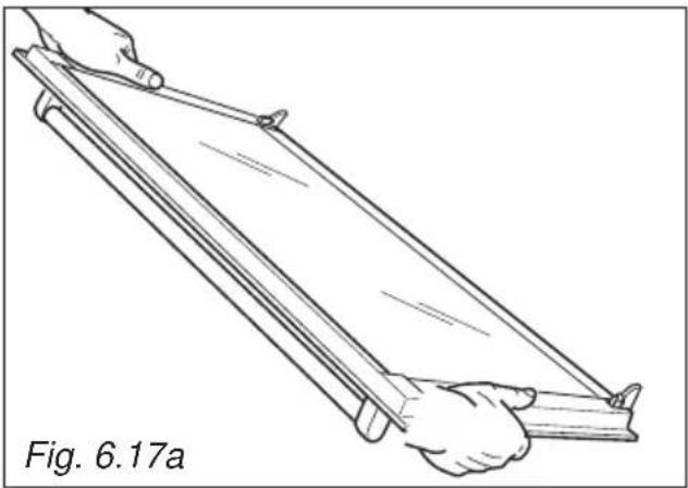
natural_image
Line drawing of two hands holding a long rectangular object, labeled Fig. 6.17a (no text or symbols on the object itself)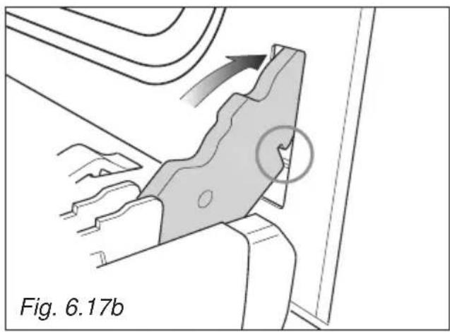
natural_image
Technical diagram showing a mechanical component with an arrow indicating direction and a circled feature, labeled Fig. 6.17b (no readable text or symbols beyond label)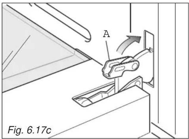
text_image
A Fig. 6.17cThe manufacturer cannot be held responsible for possible inaccuracies due to printing or transcription errors in the present booklet.
The manufacturer re serves the right to make all modifications to its products deemed necessary for manufacturer commercial reasons at any moment and without prior notice, without jeopardising the essential functional and safety characteristics of the appliances.
www.elba-cookers.com
ELBA
TALENT FOR COOKING

Made in Italy
