XOUIM1585NOASS - Fridge XO - Free user manual and instructions
Find the device manual for free XOUIM1585NOASS XO in PDF.

User questions about XOUIM1585NOASS XO
0 question about this device. Answer the ones you know or ask your own.
Ask a new question about this device
Download the instructions for your Fridge in PDF format for free! Find your manual XOUIM1585NOASS - XO and take your electronic device back in hand. On this page are published all the documents necessary for the use of your device. XOUIM1585NOASS by XO.
USER MANUAL XOUIM1585NOASS XO
EVERY THING YOU NEED TO KNOW ABOUT YOUR

text_image
XoUNDERCOUNTER NUGGET ICE MAKERS
MODELS:
XOUIMN1585NO, XOUIMN1585NOP
XOUIMN1585NOA, XOUIMN1585NOPA
I worked really hard on this manual - so please read it...


text_image
XoUNDERCOUNTER
When buying any XO appliance you can be confident you have chosen a high quality, innovative and stylish product from a company that cares about you! If you require service or have questions, Help is only a phone call away -
call: 973-403-8900
Talk to one of our undercounter experts.

text_image
STOPCONGRATULATIONS
on purchasing your XO. Before you proceed, take just a moment to register your XO at:
www.xoappliance.com/register-your-product/
Ensuring warranty coverage should you need service Providing ownership verification for insurance purposes Let's XO notify you in the event of product changes or recalls.
WHERE THINGS ARE
Before You Get Started 4 - 7
Installer Checklist
Find Your Model
Safety Instructions
Electrical and Grounding Instructions
Installation Instructions 8 - 19
Sizes and Installation Dimensions
Plumbing
With & Without Drain Pump
Reversing the Door
Door panel Installation
Operating Instructions 20 - 22
Features & Specifications
Operating Instructions
Care and Cleaning 23 - 28
Wash Function
Cleaning
Sanitization
Stainless Steel
Maintenance Schedule
Trouble Shooting 29 - 31
Before You Call For Service
Warranty
PLEASE READ AND FOLLOW ALL SAFETY INSTRUCTIONS
It's for your
own good...
Honest.
DEAR INSTALLER
HERES'S TEN STEPS FOR A QUICK & EASY INSTALL
① Inspect cabinet opening for water, drain and electrical connections.
The 1/4" O.D. water supply line must include isolation valve and should include an inline water filter (consult manual). Do NOT use a self-piecing valve for the supply connection. Water supply must have a minimum pressure of 20 psi and a maximum of 80 psi. Cold water should be between 50 F and 90°F - NOTE: warmer water will slow ice production. Water quality directly affects performance and product life - use of an inline water filter is strongly recommended.
Drain tubing will be 5/8" ID gravity fed or 3/8" ID for a pump model. All horizontal drain runs must drop 1/4" per foot. The drain should include an air gap device to prevent siphoning and a sanitary trap. A restricted or inadequate drain can result in poor ice production and possible flooding.
④ Electrical requirement is 15a dedicated, grounded circuit.
Route water supply tubing to the water inlet located at the rear of the unit. ⑤ Connect the drain tubing to either the pump discharge or the barbed gravity fed elbow. Be sure nothing is kinked, and excess slack is removed. Be sure the electrical connection is secure into the wall outlet.
⑥ Slide the machine into location or cavity being careful not to allow for any kinks to occur in the water inlet and drain tubing.
⑦ Adjust the Ice Maker to level using the leg levelers.
⑧ Add approximately 2-3 quarts of water to the bin and make certain it is draining properly and check for leaks. If water does not drain, stop and verify tubing is not restricted.
⑨ Wash down the interior of the machine with a mild detergent solution (consult manual)
Turn the machine on and allow it to make ice for approximately 30-35 minutes to verify ice is being produced and water is draining freely. Be sure to check the cube size, shape and clarity. Discard the first batch of ice. Adjust if needed.
Always do one last check to be sure all water and drain connections are leak free.
DANGER
RISK OF CHILD ENTRAPMENT!
An empty refrigerator is a very dangerous attraction to children.
Remove door gaskets, latches, lids, lock and/or doors from unused or discarded appliances, or take other actions to guarantee them harmless.
Always dispose of old appliances in accordance with local laws and regulations.
THESE ARE THE MODELS COVERED IN THIS
BOOK
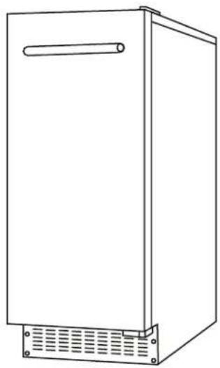
INDOOR NUGGET GOURMET ICE MAKER
natural_image
Line drawing of a rectangular cabinet with a handle and ventilation grilles (no text or symbols)STANDARD HEIGHT XOUIMN1585NO & XOUIMN1585NOP
ADA HEIGHT XOUIMN1585NOA & XOUIMN1585NOPA
TAKE A MINUTE TO CIRCLE YOUR MODEL ABOVE AND RECORD YOUR SERIAL NUMBER HERE IN CASE YOU NEED IT LATER

YOUR SAFETY MATTERS
Please read through completely before using your XO Unit
Periodic maintenance is essential for safe operation - the unit must be easily pulled out for full access.
The appliance must be positioned so that the plug and water shutoff are readily accessible.
Empty your XO unit before attempting to move the appliance. Moving while loaded may damage or distort the frame.
The compressor will get HOT during operation / touching it may cause injury.
During installation follow all safety tips provided in this manual / appropriate safety equipment such as safety glasses and work gloves should be worn.
Two people should move or lift your XO unit to prevent injury or damage.
Remove all interior and exterior packing materials prior to installation and dispose of properly.
Always use only approved cleaning and descaling products to maintain your XO Ice Maker.
For maximum efficiency, keep the door tightly shut unless removing ice.
Before installing, allow your XO unit to sit upright for 2 hours at the install site. This will allow the cooling system to stabilize after transportation. Failure to follow this step may cause problems.
Never store bottles, cans or perishable food products such as meat or cheese in your XO Ice Maker.
Location
Your XO unit should be located away from direct sunlight and heat sources (stove, heaters, etc.) which may increase electrical consumption. High or low ambient temperature may cause units to work improperly. Optimal operation occurs in the ambient temperatures of 50^ - 68^ F and water temperature of 50^ .
The floor must be strong enough to support your XO unit fully loaded.
Your XO unit must not be installed in areas of where water or excessive moisture are present.
Your XO unit must not be installed near where flammable, corrosive or hazardous materials are present.
Your XO unit's final installation must observe the correct minimum air clearances around and behind the unit to ensure adequate ventilation. In addition, all ventilation openings must be kept clear and free of obstructions, failure to do so will result in damage to the unit.
WARNING
NEVER use external heat sources to accelerate defrosting
NEVER permit unauthorized service or modifications to your XO unit
NEVER tamper with the sealed refrigerant system - this unit uses R134a Refrigerant.
It should never be used in the vicinity of any flammable or explosive ignition sources.
ALWAYS FOLLOW THE ELECTRICAL SAFETY INSTRUCTIONS OUTLINED IN THIS MANUAL.
ELECTRICITY - THIS IS SERIOUS
Failure To Follow All Electrical Safety Measures May Result in Serious Injury, Fire Or Death
All electrical work should only be performed by an experienced, licensed electrician.
All XO units MUST be grounded for safe operation and com a htiw deppiuqe e 3 Prong molded cord/plug for that purpose.
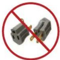
NEVER remove or disable the 3rd prong with an adapter.
NEVER use an extension cord to operate your XO unit.
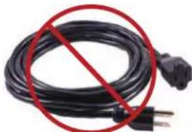
natural_image
Black cable with a red prohibition symbol crossed out, no text or symbols presentYour XO unit is built to operate on 115V 60Hz and should be plugged directly into a dedicated 15 amp 3 prong outlet. If you are uncertain as to the voltage, amperage capacity or if the 3rd prong is properly grounded - consult a licensed electrician.
To maximize the depth of the installation recess - your outlet should be mounted flush with the wall.
Your XO unit should not share the circuit with any other electrical devices as this may cause overloading, overheating, blown fuses or tripping circuit breakers. In a worst case this can pose a fire hazard.
NEVER handle your XO unit in wet conditions as this can pose a severe danger of electric shock.
Exercise care when moving your XO unit to avoid damage to the electrical cord. If the electrical cord of your XO unit becomes worn or damaged it must be replaced immediately by a qualified technician.
NEVER unplug your unit by pulling on the cord. Unplug by gripping the plug firmly and pull out straight from the outlet.
FOR INDOOR USE:
XO Ice Makers shown in this manual are rated for indoor use.
These units are designed to operate in ambient temperatures between 50° and 100°F.
Avoid installing the unit where it may be exposed to heat or direct sun, dusty or damp conditions or in a location where it may be splashed by water.
Never install the unit where flammable or corrosive chemicals (such as pool chemicals) are present.
Installation in seaside environments where high concentrations of salt are present will require more frequent cleaning to avoid corrosion.
Use in any uncontrolled area or otherwise exposed to the elements is hazardous and voids the warranty.
In regions where high humidity exists (greater than 70%) condensation may appear on the door and/or door gaskets. This is normal and will disappear as humidity drops.
SERVICE 115V - 60 Hz - 1 phase AMPS 15 Amp Circuit Breaker
Requires a Dedicated Outlet
All electrical work must be performed by a licensed electrician
State of California Proposition 65 Warning (US only) ⚠ WARNING
This product contains chemicals known to the State of California to cause cancer and birth defects or other reproductive harm. For more information go to www.P65Warnings.ca.gov

Serious injury, fire or death... Okay - You've got my attention!
A PERFECT FIT
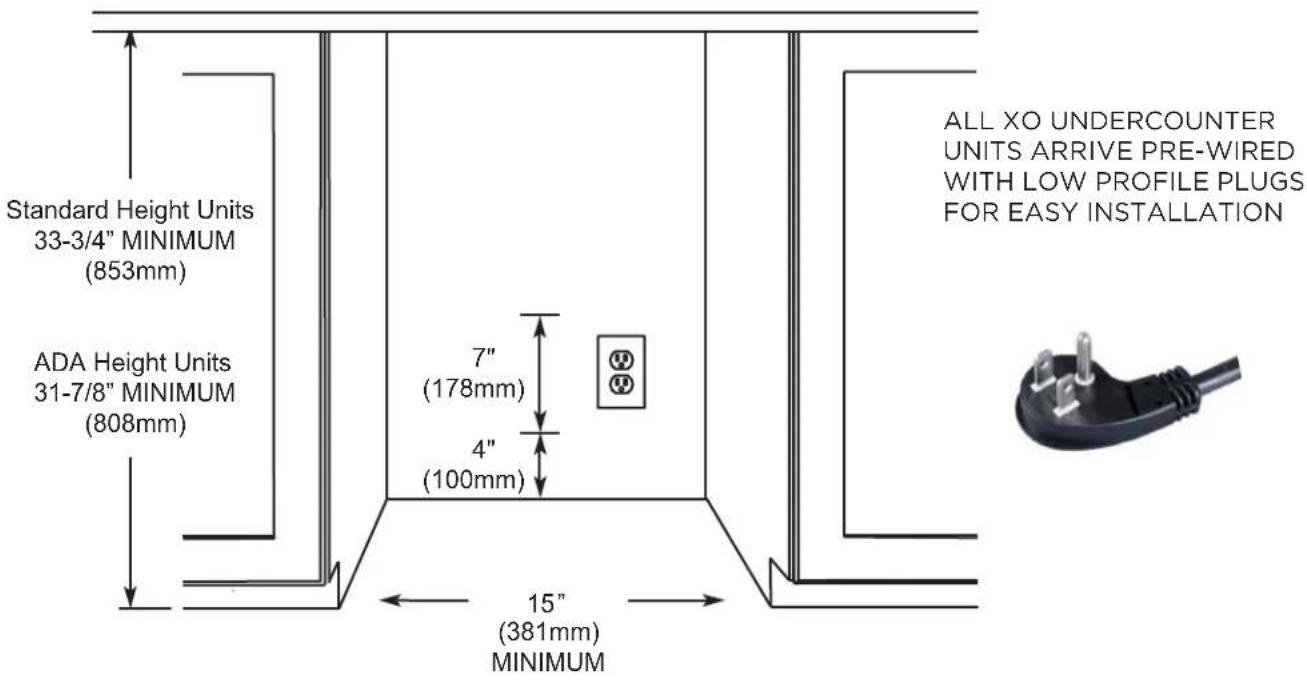
INSTALL UNDER COUNTER
text_image
Standard Height Units 33-3/4" MINIMUM (853mm) ADA Height Units 31-7/8" MINIMUM (808mm) 7" (178mm) 4" (100mm) 15" (381mm) MINIMUM ALL XO UNDERCOUNTER UNITS ARRIVE PRE-WIRED WITH LOW PROFILE PLUGS FOR EASY INSTALLATION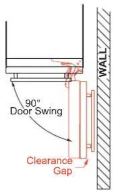
text_image
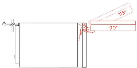
90° Door Swing Clearance Gap WALLWHEN INSTALLING WITH
LEAVE ADEQUATE SPACE FOR
YOUR DOOR HANDLE
DOOR HAS THE ABILITY TO OPEN TO 115°
text_image
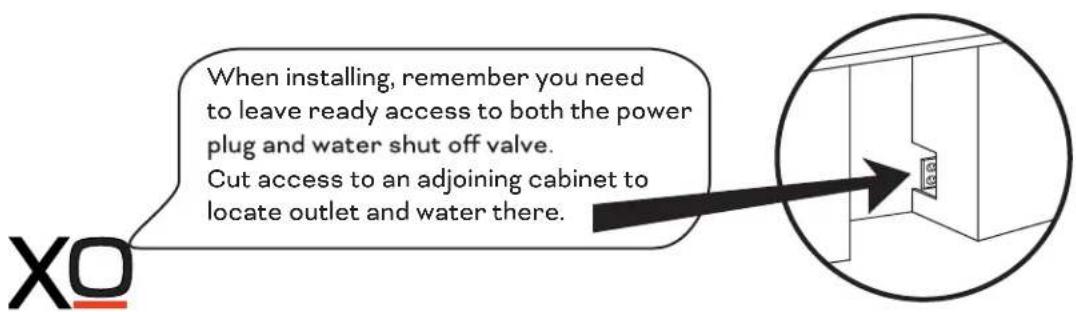
When installing, remember you need to leave ready access to both the power plug and water shut off valve. Cut access to an adjoining cabinet to locate outlet and water there.A PERFECT FIT
YOUR XO IS THIS BIG ( OR SMALL, AS THE CASE WOULD BE )
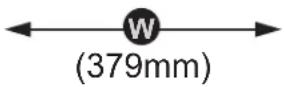
HEIGHT & WIDTH
XOUIMN1585__ & XOUIMN1585__ A ICE MAKER

natural_image
Front view of a rectangular electronic device with ventilation grilles at the base (no text or symbols visible)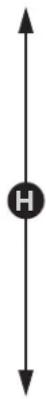
33-9/16"
STANDARD HEIGHT
(853mm)
31-13/16"
STANDARD HEIGHT
(808mm)
14-15/16" WIDE
DEPTH

natural_image
Pure architectural floor plan lines without any text, numbers, or symbols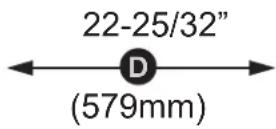
text_image
115° 90°TOP VIEW
THE OVERALL DEPTH SHOWN (22-25/32") INCLUDES THE DOOR WITH 3/4" PANEL.
THE DEPTH OF THE ICE MAKER CABINET ONLY IS 20-13/32"
BEFORE YOU INSTALL
CHECK A FEW THINGS

text_image
120V Outlet Water source tube Drain hoseIs the installation location COOL, DRY, LEVEL and away from direct sun.
The water supply valve must provide positive shut off capability and be readily accessible.
Does the unit have a dedicated 115V three prong, properly grounded outlet?
The Cold Water supply is 1/4" O.D. tube, it should be 50° to 90°F and be between 20 and 80 psi. (NOTE: as the inlet water temperature increases - production efficiency goes down.)
YOU WILL NEED -
A few simple hand tools:
Pump pliers, adjustable wrench, #2 Phillips head screwdriver, level, razor knife
AND a few hardware items:
Teflon tape or Pipe dope
5/8" I.D. drain hose and hose clamps (if installing a gravity drain model)
1/4" O.D. water supply hose
Air Gap Device and/or Sanitary Trap (depending on your installation).
Water filter with isolation valve
Depending on your installation you will probably require additional site specific plumbing fittings
WATER QUALITY
All water contains some impurities and minerals.
Your XO Ice Maker is designed to produce chewable, nugget ice. It does this by compressing ice flakes as they are forming.
PURER WATER YIELDS PURER ICE.
Cubes are formed by cold water spraying against a chilled mold. Pure water freezes faster than water containing impurities. The spraying action causes the cubes to be built up in layers as the pure water freezes more quickly and the water containing impurities is washed away by the spray and falls into the water bin to be diluted and drained away.
The ice maker uses an auger system to take the ice as it is forming in flakes and compresses them, capturing air in the process to form soft, chewable nuggets of ice.
Periodic maintenance is required to ensure that your ice maker is performing at its best. See the maintenance section of this book and the Maintenance Schedule.
FILTERS AND WATER TREAMENT
The correct filter is always recommended. It has the ability to remove odors as well as particulate from water prior to reaching the ice maker.
(consult www.xoappliance.com for more information on which filter is right for you)
Water softeners exchange one mineral for another (salt) which can cause inferior ice quality such as soft, mushy ice that clumps together. If you are using a water softener, you should install a bypass to supply untreated water to the ice maker.
Water produced by Reverse Osmosis and deionized water are not recommended. It is more corrosive than tap water and can cause harm to the equipment over time.
THE PLUMBING
Plan the arrangement of the water supply pipes. You will need both a water supply line and a drain (see section on installing a gravity drain unit or pump drain unit)
Connect a 1/4" O.D. copper tube to the COLD tap water pipe and install a shutoff valve. Do not install the shutoff valve at the back of the product. Do not use a self-piercing valve. If the tap water has a high level of minerals, an inline filter will be required.
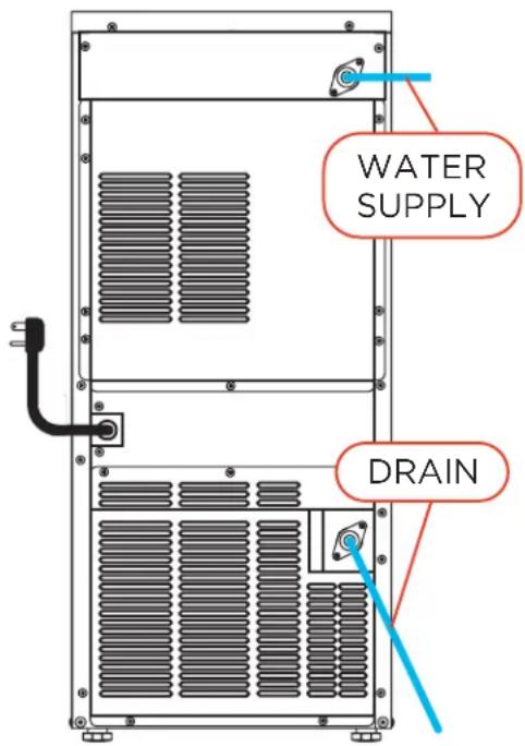
Attach the water supply line to the rear of the unit with flexible tube to the fitting indicated here. The tubing must be long enough to permit the unit to be pulled out for service.
Water supply should be between 20psi and 80psi.
Attach the drain to the connection indicated here If you are installing an XOUIMN1585NO unit with a gravity drain, the line must be pitched down 1/4" per ft to ensure correct drainage.
If the drain is positioned at a higher elevation than the connection on the rear of the unit, a pump will be required. Use model XOUIMN1586NOP. This unit comes with a pre-installed drain pump capable on discharging to a drain up to 8' above the unit.
IMPORTANT: The keep drains as short and straight as possible for optimal performance.
text_image
WATER SUPPLY DRAINThe electric power, water supply pipeline and drain pipeline must be in compliance with all provisions under the local laws and building regulations.
IMPORTANT: The product is designed for use in a fixed condition but it may be required to pull the product out for service. Therefore, do not install any material at the front, upper or lower end of the product which may be an obstacle when pulling the product out.
Once the unit is in place, use the leveling legs to ensure the unit is level. Each side should have at least 1/16" of space for projection of the screw head near the bottom.
WITH GRAVITY DRAIN
INSTALLING THE XOUIMN1585 without a drain pump.
Position the ice maker in front of the opening. Level the unit using the leveling legs.
Wash and flush the water supply tube and connect the unit to the cold water isolation valve.
Prepare the drain. The drain must be pitched downward at a drop of 1/4" per foot to drain properly.
Horizontal runs of 5' or more must be anchored to a wall for support to prevent sagging.
A sanitary trap and air gap must be installed in the line prior to entering the home's drain system.
The trap prevents sewer gas from flowing back to the ice maker.
The air gap device prevents siphoning drain water back into the ice maker.
Cut the 5/8" ID drain hose (not supplied) to the required length. Immerse the hose in warm water to make installation easier, then using a threaded hose barb connection sealed with teflon tape, connect the drain hose to the drain using hose clamps.
Turn the water supply on and check to ensure there are no leaks.
If there are no leaks, plug the unit into the electrical outlet.
Press the switch to the "ICE" position. The compressor will run approximately 3 - 5 minutes.
Slide the unit back into it's final position and recheck to ensure it is level.
REMEMBER to adhere to all local building codes and regulations

text_image
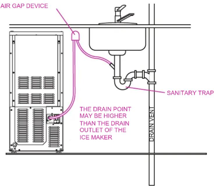
If you purchase a gravity drain unit and find you need one with a pump the XOUIMN1585 can easily be retrofitted with one in the field. Simply order a XOUIMPUMP from www.xoappliance.com THE DRAIN POINT MUST BE LOWER THAN THE DRAIN OUTLET OF THE ICE MAKER AIR GAP DEVICE SANITARY TRAP DRAIN VENTWITH DRAIN PUMP
INSTALLING THE XOUIM1565SP with DRAIN PUMP.
Position the ice maker in front of the opening.
Level the unit using the leveling legs.
Wash and flush the water supply tube and connect the unit to the cold water isolation valve.
Cut the 3/8" diameter drain hose to the required length. Immerse the hose in warm water to make installation easier, then connect the drain hose to the drain using hose clamps.
(9' of 3/8" ID drain hose is included with pump models)
IMPORTANT: Check local codes to determine if an air gap is required between the drain and the pump.
Turn the water supply on and check to ensure there are no leaks.
If there are no leaks, plug the unit into the electrical outlet.
Fill the ice container with clean tap water approximately 3/4 full. The drain pump should turn on and pump the water out. Check again for leakage.
Press the switch to the "ICE" position. The compressor will run approximately 3 - 5 minutes.
Fill the ice container to 3/4 full once more. Block the drain tube while the pump is running. The pump should continue to run.
Slide the unit back into it's final position and re-check to ensure it is level.
REMEMBER to adhere to all local building codes and regulations
text_image
AIR GAP DEVICE SANITARY TRAP THE DRAIN POINT MAY BE HIGHER THAN THE DRAIN OUTLET OF THE ICE MAKER DRAIN VENTREVERSING THE DOOR
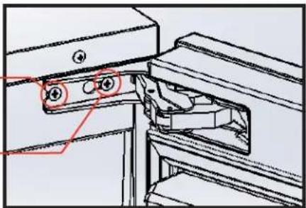
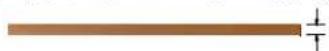
Your XO Ice Maker is shipped with the hinge on the right hand side but it can be easily reversed.
-
Remove the inner most screw holding the top and bottom hinges (shown here)
-
Loosen the outer screw holding the top and bottom hinges (as show here)
-
Slide the door and hinges sideways to remove from the cabinet.
text_image
Technical diagram showing a mechanical assembly with numbered components and highlighted parts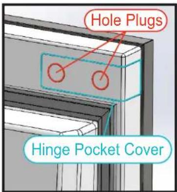
text_image
Hole Plugs Hinge Pocket Cover-
On the opposing side of the door, remove the Hole Plugs and screws from the left hand hinge locations.
-
Remove the Hinge Pocket Covers from the left hand hinge locations.
-
Remove the two hinges, rotate them 180 and screw them into place on the left hand side where the Hinge Pocket Covers were just removed.
-
Rotate the Hinge Pocket Covers 180 and install them to cover the right hand hinge location.
-
Use the Hole Plugs to hide the screws holding the Hinge Pocket Covers in place.
-
Move the outer screws loosen in Step 2 to the corresponding hole on the left hand side of the cabinet but do not tihten down yet.
-
Place the door onto the screws installed in Step 9 and side in toward the center of the cabinet so that second screwhole is visible.
-
Install the screws removed in Step 1. Make certain the door is centered properly and tighten all four (4) hinge screws.
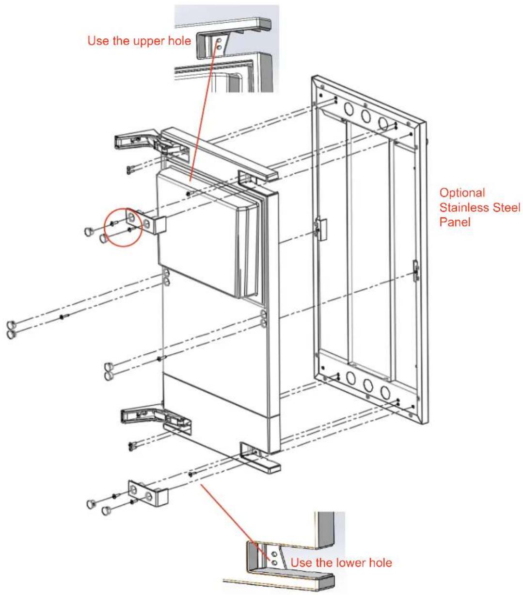
INSTALLING THE DOOR PANEL
The panel is held in place by self tapping screws and/or machine screws.
To install your panel, follow these simple steps:
- First prepare your custom panel.
The panel must be 14-7/8" wide and no more than 3/4" thick. It cannot weigh more than 20 lbs. The height of the panel can vary but cannot block the free exchange of air through the toekick. If you are using one of the optional Stainless Steel door panels (XOUIMN15S or XOUIMN15ADA) it is ready to install out of the box, simply peel off the protective layer of plastic before installing.
-
If your cabinetry uses a handle, locate and attach it before mounting the panel. Remember to recess the screw heads.
-
If installing a custom panel, clamp the panel in position on the open door being careful not to damage the panel or door liner. Use the 14 self tapping screws provided to secure the panel as outlined on the exploded diagram shown on the next page. Check the screw depth if your panel is less than 3/4" thick to ensure the screw points do not protrude through the panel. If using one of the optional Stainless Steel door panels, using the machine screws provided, secure the panel with the 14 machine screws supplied as outlined on the exploded diagram shown on the next page.
-
Install Hole Covers as required and remove the clamps.
LET'S FACE IT
text_image
Use the upper hole Optional Stainless Steel Panel Use the lower holePANEL MAXIMUM WEIGHT: 20 lbs.
MAXIMUM PANEL THICKNESS 3/4"
LET'S FACE IT
OVERTAY PANEL DIMENSIONS XOUIMN1585NO & XOUIMN1585NOP
OUIMN1585NOADA & XOUIMN1585NOPADAX
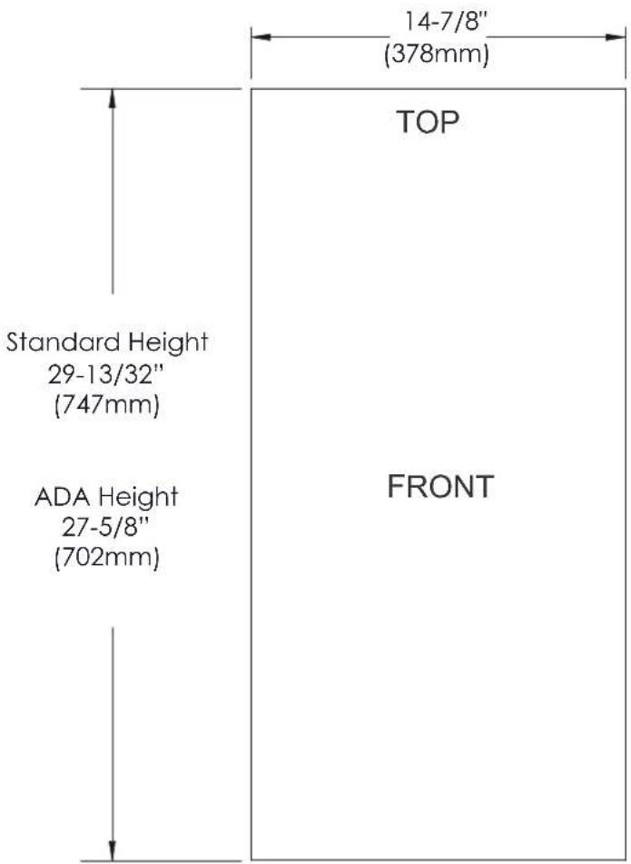
text_image
14-7/8" (378mm) TOP Standard Height 29-13/32" (747mm) ADA Height 27-5/8" (702mm) FRONTPANEL HEIGHTS ARE MINIMUMS, PANEL MAY BE TALLER. PANEL MUST NOT INTERFERE WITH TOEKICK VENTS. AFTER INSTALLATION UNDERCOUNTER DOOR MUST BE ABLE TO OPEN 90°
PANEL MAXIMUM WEIGHT: 20 lbs.
MAXIMUM PANEL THICKNESS 3/4"
LET'S FACE IT
THE TOEKICK
PANELS MAY EXTEND HIGHER OR LOWER THAN THE DOOR BUT MUST NOT OBSTRUCT THE FREE EXCHANGE OF AIR THROUGH THE TOEKICK.

natural_image
Pure architectural or mechanical diagram showing a vertical panel with a green wall and red/blue directional arrows, no text or symbols present.
natural_image
Green rectangular panel with two side-mounted blocks and two directional arrows pointing to the bottom (no text or symbols)FEATURES & SPECS
Produces up to 85lbs of nugget ice per day
Stores 24.3lbs of ice in bin
Chewable, Nugget Ice
Gravity drain and pump drain models available
Reversible Door | Panel Ready (optional SS panel)
Rated for Indoor use (50° - 100°)
natural_image
Isometric line drawing of a 3D rectangular box with a vertical seam and internal structure (no text or symbols)Front venting - designed for under counter installation
Automatically pauses ice production when bin is full
| MAXIMUM CAPACITY | 85 lbs per day |
| ICE SHAPE | Nugget |
| INITIAL TIME TO FILL BIN | 10 Hours |
| DIMENSIONS (WxDxH)* | 14 15/16" x 23 3/8" x see below* |
| NET WEIGHT | 126 lbs empty |
| ELECTRICAL | 115V - 60hz - 3.3 amps |
| POWER CONSUMPTION | 550 Watts |
| REFRIGERANT | R-134a |
| COOLING CAPACITY | 723 kcal/hr (2@ 45 °F) |
| INLET WATER TEMP. | 50° - 90° F |
| INLET WATER PRESS. | 20 - 80 psi |
| AMBIENT TEMP. | 50° - 100° F |
* Overall Height for Standard Unit 33-9/16"
Overall Height for ADA Unit 31-13/16"
OPERATION
You XO Ice Maker is simple to operate.
When you open the door you will see the electronic button/display located at the top center of the appliance.

text_image
LAMP ICE NO WATER DRAINThe first button, LAMP, allows you to cycle through the 5 different interior LED Light colors (white, Dark Blue, Green, Red and Light Blue).
The ICE light will always come on first when the unit is switched on. Initially, the unit will automatically fill and drain water three times then, the ice making cycle will begin.
The NO WATER light will come on to indicate there is a problem with the water supply.
The DRAIN light will come on when the drain valve is open.
INITIAL OPERATION:
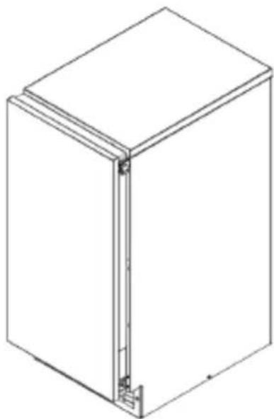
When you open the door, located at the bottom, right of the face of the unit is a three position toggle switch.
The center position is OFF. The top position is ICE. The bottom position is WASH.
text_image
ICE OFF WASHTurn the appliance to ICE, this will start the ice making process.
Always discard the first batch of ice. Good quality ice is produced in 1-2 hours.
OPERATION CONT.
DURING OPERATION:
After turning the switch to the ICE position, ice production will begin and continue until the ice bin has been filled.
Once the bin is filled, production will automatically be paused.
Remove ice using the handy scoop located in a holder in the top left hand side of the interior.
It takes approximate 10 hours to fill the ice bin, this time may vary based on ambient and water temperatures.
NUGGET ICE:
Nugget ice is a smaller softer cube ideal for drinks requiring “Chewable Ice”. Ice is formed in layers that are compressed together by a rotating auger and ejected upward.
Impurities sink in the drum and are removed periodically by the drain. These commonly fracture in smaller pieces creating the “Nuggets”.

text_image
0.8" 0.5" 0.8"approximate size in inches, image not to scale
NOTE:
As ice melts, the residual water is drained away. This will continue to occur even when the ice maker is shut off. Models with a drain pump will cycle automatically to remove collected water periodically when ice production is shutdown. This is normal. Pump operation is only a few seconds in duration.
IMPORTANT:
Never store bottles, cans or other items in the ice maker. This can be unsanitary, contaminating the ice and detached labels or packaging can block the drain.
MAINTENANCE
Proper maintenance, cleaning and santizing is essential to ensure your ice is safe, fresh and odor free.
WASH FEATURE:
Regular maintenance is the key to delicious, wholesome ice.
The WASH feature helps make this easy to perform.
When the WASH Position of the switch is selected, the cleaning process takes approximately 10 minutes and the following action take place:
BEFORE BEGINNING - REMOVE ALL ICE FROM THE ICE BIN.
- Water is supplied to the first water tank and the auger operates for 5 minutes.
NOTE: You may optionally add cleaning solution (see CLEANING) to the ice outlet.
- After Step 1 is complete, drain and re-fill with water.
- Operate the Auger for 1 minute.
- Repeat Steps 2 and 3, twice more for a total of 3 times.
- Drain and stop the product. When restarting follow the procedures for an initial start, discarding the first batch of ice.
MAINTENANCE CONT.
Proper maintenance, cleaning and santizing is essential to ensure your ice is safe, fresh and odor free.
CLEANING:
BEFORE BEGINNING - REMOVE ALL ICE FROM THE ICE BIN.
- Prepare by mixing 0.25l of a non-toxic, nickle-safe Ice Maker cleaning solution and 5l of water.
- Open the door and pour approximately 1 liter of cleaning solution into the ice spout located at the top, rear of the unit.
- Toggle the lower front mode switch to "WASH".
The ice maker automatically cleans, drains and supplies water repeatedly, which takes about 10 minutes.
Use a brush or cloth to clean the inside of the reservoir with the remaining cleaning solution.
After 10 minutes have elapsed, rinse the inside of the reservoir with clean water and pour water into the ice spout.
Toggle the mode switch to "WASH" once again.
After about 10 minutes, the cleaning processes will finish.

text_image
ICE SPOUT ICE SCOOPMAINTENANCE CONT.
Proper maintenance, cleaning and santizing is essential to ensure your ice is safe, fresh and odor free.
SANITIZING:
BEFORE BEGINNING - REMOVE ALL ICE FROM THE ICE BIN.
- Prepare by mixing 0.25l of a Ice Maker sanitizer solution and 5l of water.
WARNING: Observe all safety precautions including the use of protective eyewear and gloves while using sanitizer.
Read and observe all manufacturers instructions carefully.
- Open the door and pour approximately 1 liter of cleaning solution into the ice spout located at the top, rear of the unit.
- Toggle the lower front mode switch to "WASH".
The ice maker automatically cleans, drains and supplies water repeatedly, which takes about 10 minutes.
Use a brush or cloth to clean the inside of the reservoir with the remaining santizing solution.
After 10 minutes have elapsed, rinse the inside of the reservoir with clean water and pour water into the ice spout.
Toggle the mode switch to "WASH" once again.
After about 10 minutes, the sanitizing processes will finish.
STAINLESS STEEL
CLEANING THE EXTERIOR
Stainless Steel:
Stainless steel does not stain, corrode, or rust as easily as ordinary steel, but it is not stain or corrosion proof. Stainless steels can discolor or corrode if not maintained properly.
Stainless steels differ from ordinary carbon steels by the amount metals such as chromium and nickel used in the alloy. It is the chromium which provides an invisible protective film on the surface called chromium oxide. If the protective chromium oxide film on the surface is damaged or contaminated, it can result in discoloration, staining, or corrosion of the iron in the steel.
Care & Cleaning:
Routine cleaning of the stainless steel surfaces will serve to greatly extend the life of your product by removing contaminants.
This is especially important in coastal areas which can expose the stainless to severe contaminants such as halide salts, (sodium chloride) and also in pool areas where high concentrations of chlorine are present.
It is strongly recommended to periodically inspect and thoroughly clean crevices, weld points, under gaskets, rivets, bolt heads, and any locations where small amounts of moisture could collect, become stagnant, and concentrate contaminates.
Additionally, any mounting hardware that is showing signs of corrosion should be replaced.
The frequency of cleaning depends upon the installation location, environmental factors, and use.
Cleaning Products:
Ultimately, the choice of a proper cleaning product belongs to the consumer, and there are many products to choose from. Depending upon the type of cleaning and the degree of contamination, some products are better than others.
Typically the most effective means of routine cleaning for most stainless steel products is to give the surfaces a brisk rubbing with a soft cloth soaked in warm water with a gentle detergent, or mild mixture of ammonia.
Rubbing should follow the polish lines of the steel, followed by a thorough rinsing after cleaning.
CAUTION: There are products on the market called "stainless steel cleaners," which may contain abrasives that could scratch the surface, (compromising the protective chromium oxide coating) and other products which contain chlorine bleach which will dull, tarnish or discolor the surface if not completely removed. Such cleaners should be avoided.
THE CONDENSER
IMPROVE EFFICIENCY & PERFORMANCE
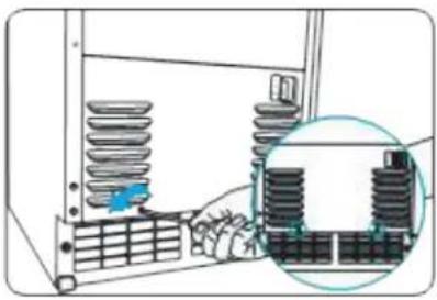
Cleaning the condenser
Remove dust and dirt from the surface of the condenser coils with a vacuum cleaner
Remove two screws on the front panel at the center of the inside
natural_image
Diagram of a server rack with insulators and a magnified inset showing internal components (no text or symbols)Vacuum the condenser coils
natural_image
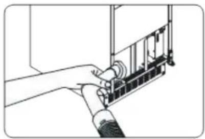
Line drawing of a hand connecting a mechanical component to a wall-mounted device (no text or symbols)Reassemble the panel using the two screws to after cleaning

natural_image
Illustration of a hand inserting a spring into a rack, with no visible text or symbolsMAINTENANCE SCHEDULE
。
The following maintenance schedule is a guideline.
Maintenance and repairs should be performed more frequently where required by water quality, equipment usage and local hygiene regulations.
| FREQUENCY | AREA | TASK |
| DAILY | Scoop | Clean with neutral cleaner / rinse thoroughly |
| MONTHLY | Water filter | Check dressure drop / change as needed |
| Exterior of unit | Wipe down with clean soft cloth. Use neutral cleaner on damp cloth to remove oils or dirt. Clean any chlorine rust stains using a non-abrasive cleanser. | |
| Storage bin inner door and Ice spout | Wipe clean with a clean cloth and warm water inner door and ice spout | |
| 6 Months | Ice maker and Storage bin | Clean and sanitize according to the instructions in this manual. |
| Evaporator Condensate Drain and Gear Motor Drain Pan. | Wipe down with clean cloth and warm water. | |
| Ice maker and reservoir | Check that it is kept clean | |
| Ice exit fixing bolt | Check for leaks around seal Always replace O-Ring if bolt is removed | |
| Annually | Water supply valve and Drain Valve | Close water supply valve and drain water |
| Water Hose | Check water hose, clean as necessary | |
| Condenser | Inspect and clean with brush and vacuum, if dust adhesion is severe, spray with pin cleaning agent, rinse and dry | |
| Ice maker | Inspect for oil marks, loose components and wire |
Bearing and mechanical seal maintenance must be performed by a qualified service technical annually
WHAT THE CONTROL LIGHTS MEAN
| PROBLEM | ICE | NO WATER | DRAIN | POSSIBLE CAUSE | ACTION |
| Making Ice | O | Switch in "ICE" position | |||
| Washing | B | Switch in "WASH" positionICE lamp blinks once per second | Switch in "WASH" positionICE lamp blinks once per second | ||
| Bin Full | B | ICE lamp blinks every 2 seconds | Will turn off when sensor detects release temperature | ||
| Draining | O | Drain valve is open | |||
| Water Supply Error | B | Water level not detected(for 2 minutes) | Water pressure and level checkStart operation after action | ||
| Drain Error | B | Water level lower limit is undetected after 2 minuteswhile drain is open | Check if draining properlyReplace water level sensorCall for service | ||
| Evap Temp Error | B | B | B | Evaporator temp is 32^ or higherafter 30 minutes with Ice Making ON | Call for service |
| Evap Temp Error | B | Evaporator temp is 32^ or higherafter 10 minutes with Ice Making ON | Call for service | ||
| Ice Full Sensor Error | B | B | ICE FULL temperature sensordisconnected of shorted | Sensor disconnected of shortedCall for service | |
| Evap Temp Sensor | B | B | Evaporator temperature sensordisconnected of shorted | Sensor disconnected of shortedCall for service | |
| Air Temp Sensor Error | B | B | Air temperature sensor(front of condensor)disconnected of shorted | Sensor disconnected of shortedCall for service | |
| Evap Freezing | O | O | O | Evaporator outlet temperature drops below setting for 2 minutes while ice maker is running | Occurs when ambient temperature is low.Increase room temperature above 50^ F. |
O=ON B=BLINKING
Questions - Need Help...
You can always contact customer service at 973-403-8900
or visit www.xoappliance.com
TROUBLESHOOTING
| PROBLEM | POSSIBLE CAUSE | ACTION |
| Ice maker not operating | No power | Unit unplugger / plug inBreaker thrown / rest breaker |
| Switch in wrong position | Change switch to ICE position | |
| Storage bin full | Operating normally - production ceases when bin is fullRoom temp below 50°/ raise room temp. | |
| Drain blocked | Clear drain tube | |
| Drain pump malfunction | Call for service | |
| Cubes too large | Cube size temp set too low | Call for service |
| Ice quality inconsistent | Not enough water | Check filter may be restricting water flowCheck water valve, inlet screen may be restricted |
| Sound level has increased | Scale has formed in drum | Clean with approved Ice Maker Cleaner |
| Makes ice but bin does not fill | Storage bin drain may be restricted | Clean out and check drain |
| Ice partially formed | Possible scale in evaporator | Clean with approved Ice Maker Cleaner |
| Unit operates but no ice is produced | Ice stuck in evaporator | Check water supply - filter may be restricting water flowCheck water valve, inlet screen may be restrictedCall for service |
| Water temperature is too high | Inlet water valve may be leaking - call for service | |
| Inadequate air flow | Obstructed toe kick vents - clear obstructionDamaged cooling fan - call for serviceCondenser blocked - clean condenser | |
| Compressor not operating | Call for service | |
| Low refrigerant | Call for service | |
| Hot gas valve leaking | Call for service |
Questions - Need Help... You can always contact customer service at 973-403-8900 or visit www.xoappliance.com
WE'VE GOT YOUR BACK
ONE-YEAR PARTS & LABOR LIMITED WARRANTY. XO warrants to the original purchaser of every new XO ice maker unit, the cabinet and all parts thereof, to be free from defects in material or workmanship under normal and proper use and maintenance as specified by XO and upon proper installation and start-up in accordance with the instruction packet supplied with each XO unit. XO's obligation under this warranty is limited to a period of one (1) year from the date of original purchase.
FIVE-YEAR COMPRESSOR LIMITED WARRANTY. XO warrants its compressor to be free from defects in both material and workmanship under normal and proper use and maintenance service for a period of five (5) years from the date of original purchase. If the compressor fails during that time period due to a defect in material or workmanship, XO will supply a replacement compressor free of charge. The consumer will be responsible for all related transportation and labor costs. Product must be registered with XO to qualify for this warranty.
TERMS APPLICABLE TO EACH WARRANTY. Any part covered under the above warranties that is determined by XO to have been defective within the time frame is limited to the repair or replacement, including labor charges, of defective parts or assemblies. The labor warranty shall include standard straight time labor charges only and reasonable travel time, as determined by XO.
WARRANTY CLAIMS. All claims for labor or parts must be made directly through XO. All claims should include: model number and serial number of cabinet, proof of purchase, and date of installation. In case of warranted compressor, the compressor model tag must be returned to XO along with the above listed information.
WHAT IS NOT COVERED BY THIS WARRANTY. XO's sole obligation under this warranty is limited to either repair or replacement of parts, subject to the additional limitations below. This warranty neither assumes nor authorizes any person to assume obligations other than those expressly covered by this warranty. Open box, factory seconds, scratch and dent, floor models, models with missing, altered or obscured serial numbers and commercial applications are excluded from these warranties. Consumer shall be responsible for labor and transportation costs where noted above.
NO CONSEQUENTIAL DAMAGES. XO is not responsible for economic loss, profit loss; or special, indirect or consequential damages, including without limitation, losses or damages arising from food or product spoilage claims whether or not on account or refrigeration failure.
WARRANTY IS NOT TRANSFERABLE. This warranty is not assignable and applies only in favor of the original purchaser/user at the original installation location. Any such assignment or transfer shall void the warranties herein made and shall void all warranties, express or implied, including any warranty or merchantability or fitness for a particular purpose.
IMPROPER USAGE. XO assumes no liability for parts or labor coverage for component failure or other damages resulting from improper usage or installation or failure to clean and/or maintain product as set forth in the warranty packet provided with the unit.
ALTERATION OR NEGLECT. XO is not responsible for the repair or replacement of any parts that XO determines have been subjected after the date of manufacture to alteration, neglect, abuse, misuse, accident, damage during transit, improper installation, lack of scheduled maintenance as outlined in this manual, fire, flood, or act of God.
SERVICE CONNECTIONS. XO is not responsible for the repair or replacement of failed or damaged components due to water supply, drain or electrical power failure, high or low pressure, blocked drains, high or low voltage, use of extension cords, or improper grounding of the unit.
YOUR RIGHTS UNDER STATE LAW. This warranty gives you specific legal rights and you may have other rights that vary from state to state. Some states do not allow the exclusion or limitation of consequential damages or a limitation on how long an implied warranty lasts, so the above exclusion or limitation may not apply to you.
OUTSIDE U.S. This warranty does not apply to, and XO is not responsible for, any warranty claims made on products sold or used outside the 48 continental United States.
To obtain service:
Call 973-403-8900 | email service@xoappliance.com | or submit a request on our website www.xoappliance.com

text_image
1 YEAR PARTS + LABOR C WARRANTY
text_image
5 YEAR PRESSOR WARRANTYSEE ALL THE LATEST XO PRODUCTS AND ACCESS PARTS AT: WWW.XOAPPLIANCE.COM