VT-OHS35K-100 - Lampe à batterie V-TAC - Free user manual and instructions
Find the device manual for free VT-OHS35K-100 V-TAC in PDF.

User questions about VT-OHS35K-100 V-TAC
0 question about this device. Answer the ones you know or ask your own.
Ask a new question about this device
Download the instructions for your Lampe à batterie in PDF format for free! Find your manual VT-OHS35K-100 - V-TAC and take your electronic device back in hand. On this page are published all the documents necessary for the use of your device. VT-OHS35K-100 by V-TAC.
USER MANUAL VT-OHS35K-100 V-TAC
natural_image
Two white rectangular electronic devices with black buttons, one labeled 'V-TAC' and the other showing a square display (no text or symbols on the devices themselves)| SKU | MODELDESCRIPTION | |
| 12151 | OHS-HV100 | HIGH VOLTAGE BATTERY CLUSTER CONTROL BOX |
| 12002 | OH-5K | 51.2V 100AH RECHARGEABLE LI-ION BATTERY MODULE |
| 12152 | OH-BASE | BATTERY MODULE BASE |
INTRODUCTION
Thank you for selecting and buying V-TAC Product. V-TAC will serve you the best. Please read these instructions carefully & keep this user manual handy for future reference. If you have any another query, please contact our dealer or local vendor from whom you have purchased the product. They are trained and ready to serve you at the best.

text_image
QR code image containing encoded data, no visible human-readable textMULTI-LANGUAGE MANUAL QR CODE
Please scan the QR code to access the manual in multiple languages.

1. Introduction....3
1.1 Important Safety Instructions....3
1.2 Symbols....4
1.3 Brief Introduction....5
1.4 Product Properties 5
2. Product Specification....6
2.1 Size and Weight 6
2.2 Performance Parameter 7
2.3 Equipment Interface Instruction 8
3. OHS'S User Interface 10
3.1 Main Interface 10
3.2 Cell Voltage 11
3.3 Cell Temperature....11
3.4 Heating Temperature....12
3.5 Relay Status....12
3.6 Other 13
3.6.1 Heating Information....13
3.6.2 Insulation Resistense....14
3.6.3 Diagnostic Information....14
3.6.4 Cumulative Time Information....15
3.7 Set Up....15
4. Xiaodan Energy Storage App....16
4.1 App download 16
4.1.1 Android version.... 16
4.1.2 iOS version....17
4.2. Log in and register 17
4.2.1 Log in....17
4.2.2 Register....18
4.2.3 Experience login 19
4.3. Equipment distribution network....20
4.3.1 Overview....20
4.3.2 Distribution process.... 20
4.4. App page 25
4.4.1 Equipment 25
4.4.2 Data details....28
4.4.3 Mine 28
4.4.4 Message 33
4.4.5 App settings....34
Installation and Configuration 36
5.1 Preparation for installation.... 36
5.1.1 Safety Requirement .... 36
5.1.2 Environmental requirements.... 36
5.1.3 Tools and data....37
5.1.4 Technical preparation....37
5.1.5 Unpacking inspection 37
5.2 Equipment installation....39
5.2.1 Installation Steps....39
5.2.2 Battery parameter settings on the inverter....41
- Installation and Configuration 41
6.1 Battery system usage and operation instructions.... 41
6.2 Alarm description and processing....42
6.3 Analysis and treatment of common faults....42
7 Battery Module Storage 43
8 Maintenance....44
RoHS


1. Introduction
1.1 Important Safety Instructions

Danger!
- Please do not put the battery into water or fire, in case of explosion or any situation that might endanger your life.
- Please connect wires properly while installation, do not reverse connect. To avoid short circuit, please do not connect positive and negative poles with conductor on the same device.
- Please avoid any form of damage to battery, especially stab, hit, trample or s

Danger!
- Please shut off the power completely when removing the device or reconnecting during the daily use or it could cause the danger of electric shock.
- Please use dry powder extinguisher to put out the flame when encountering a fi hazard, liquid extinguisher could result in the risk of explosion.
- For your safety, please do not arbitrarily dismantle any component in any circumstances. The maintenance must be implemented by authorized technical personnel or our company's technical support. Device breakdown due to unauthorized operation will not be covered under warranty.

Caution!
- Our products have been strictly inspected before shipment. Please contact us if you find any abnormal phenomena such as device outer case bulging.
●The product shall be grounded properly before use in order to ensure your safety
●To assure the proper use please make sure parameters among the relevant device compatible and matched.
- Please do not mixed-use batteries from different manufacturers, different types and models, as well as old and new together.

Caution!
- Ambient and storage method could impact the product life span, please comply with the operation environment instruction to ensure device works in proper condition.
- For long-term storage, the battery should be recharged once every 6 months, and amount of electric charge shall exceed 80% of the rated capacity.
- Please charge the battery in 18 hours after it fully discharged or over-discharging protection mode is activated.
●Formula of theoretical standby time: T=C/I (T is standby time, C is battery capacity total current of all loads).
1.2 Symbols
| Symbols | Description |
 | Warning electric shock. |
 | Caution! Warning! Reminding.Safety related information.Risk of battery system failure or life cycle reduces. |
 | Warning Fire.Do not place near flammable material |
 | Do not place near open flame. |
 | Read the product and operation manual before operating the battery system! |
 | Grounding. |
 | The certificate label for EMC/CE. |
 | The certificate label for UKCA. |
 | Label for Waste Electrical and Electronic Equipment (WEEE) (2012/19/EU) |
1.3 Brief Introduction
51.2V100AH lithium iron phosphate battery system is a standard battery system unit, customers can choose a certain number of 51.2V100AH according to their needs, by connecting series to form a larger capacity battery pack, to meet the user's long-term power supply needs. The product is especially suitable for energy storage applications with high operating temperatures, limited installation space, long power backup time and long service life.
1.4 Product Properties
51.2V100AH energy storage product's positive electrode materials are lithium iron phosphate, battery cells are managed effectively by BMS with better performance, the system's features as below:
●The whole module is non-toxic, non-polluting and environmentally friendly;
●Cathode material is made from LiFePO4 with safety performance and long cycle life
●Battery management system with better performance, possesses protection
function like over-discharge, over-charge, over-current, abnormal temperature.
●Self-management on charging and discharging, Single core balancing function.
●Intelligent design configures integrated inspection module.
- Flexible configuration, multiple battery modules can be in parallel for expanding capacity and power.
●Flexible configurations allow parallel of multi battery for longer standby time.
●Self-ventilation with lower system noise.
●Less battery self-discharge, then recharging period can be up to 10 months during the storage.
●No memory effect so that battery can be charged and discharged shallowly.
- With wide range of temperature for working environment, -10^ +55^ , circulation span and discharging performance are well under high temperature.
2. Product Specification
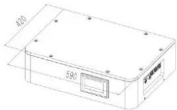
2.1 Size and Weight
51.2V100Ah Module


text_image
420 590High voltage battery cluster control box

text_image
400 590Module Cluster

text_image
420 840 590Battery module base


text_image
420 590Table 2-1 Device size
| Product | Nominal Voltage (V) | Nominal Capacity (Ah) | Dimension (mm) | Weight (Kg) |
| OHS15K-100 | 153.6 | 100 | 590*420*698 | 173.9 |
| OHS20K-100 | 204.8 | 100 | 590*420*849 | 222.4 |
| OHS25K-100 | 256 | 100 | 590*420*1000 | 270.9 |
| OHS30K-100 | 307.2 | 100 | 590*420*1151 | 319.4 |
| OHS35K-100 | 358.4 | 100 | 590*420*1302 | 367.9 |
| OHS40K-100 | 409.6 | 100 | 590*420*1453 | 416.4 |
2.2 Performance Parameter
Table 2-2 performance parameter
| Technical specification | 15KWH | 20KWH | 25KWH | 30KWH | 35KWH | 40KWH |
| Installation Mode | Stackable | |||||
| Battery Type | LifePO4(LFP) | |||||
| Module Energy(kWh) | 5.12 | |||||
| Module Nominal Voltage(V) | 51.2 | |||||
| Module Capacity(Ah) | 100 | |||||
| System Model | OHS15K-100 | OHS20K-100 | OHS25K-100 | OHS30K-100 | OHS35K-100 | OHS40K-100 |
| Battery Module Qty InSeries(Optional) | 3 | 4 | 5 | 6 | 7 | 8 |
| System Nominal Voltage(V) | 153.6 | 204.8 | 256.0 | 307.2 | 358.4 | 409.6 |
| System Nominal Capacity(KWh) | 15.36 | 20.48 | 25.60 | 30.72 | 35.84 | 40.96 |
| Usable Capacity(KWh) | 12.29 | 16.38 | 20.48 | 24.58 | 28.67 | 32.77 |
| Dimension (mm) | 590*420*698 | 590*420*849 | 590*420*1000 | 590*420*1151 | 590*420*1302 | 590*420*1453 |
| Weight (Kg) | 173.9 | 222.4 | 270.9 | 319.4 | 367.9 | 416.4 |
| Recommend Charge/Discharge Current (A) | 40 | |||||
| Recommend charging method declared by the manufacturer | Charge at constant current 50A until cell voltage reaches 3.5V, then charge at until cell voltage reaches 3.6V, | |||||
| Communicaiton | CAN | |||||
| Ingress Protection | IP65 | |||||
| Altitude | ≤2000m | |||||
| Cycle Life | 25±2°C,0.5C/0.5C,EOL70%≥6000 | |||||
| Monitoring Parameters | System voltage,Current,cell voltage,cell temperature | |||||
| SOC | Intelligent algorithm | |||||
| Working Temperature | 0°C-45°C Charge -10°C -55°C Discharge | |||||
| Storage Temperature | 0~35°C | |||||
2.3 Equipment Interface Instruction
2.3.1 This section details the front and back interface functions of the battery pack
Product Front Interface
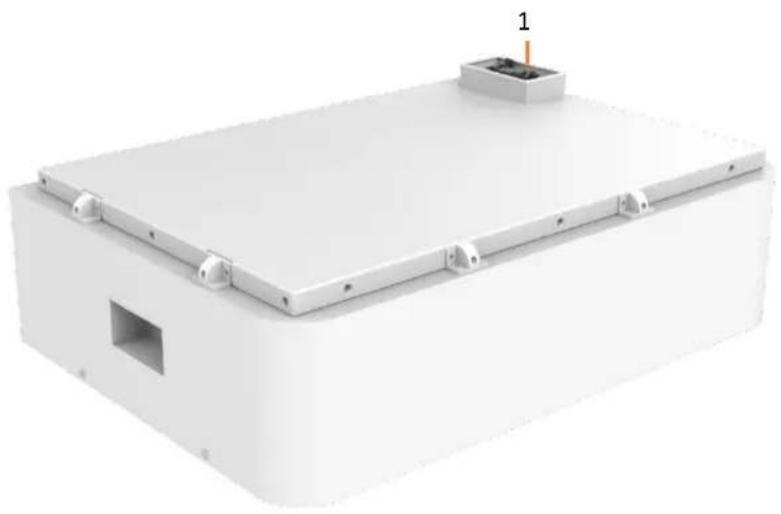
natural_image
3D rendering of a white rectangular electronic enclosure with mounting brackets and a small vent, no visible text or symbols.Control Box Module Front Interface

text_image
V-TAC MeaningAI innovation 2 4 3 5 OFFION 6 7 8 9 10 11 CCM1 CCM2 CCM3Table 2-3 Interface Definition
| Item | Name | Definition |
| 1 | Power Connector | For battery pack connect in series |
| 2 | Screen | Show battery information |
| 3 | Air Switch | Current Protection |
| 4 | BMS ON/OFF | Start BMS |
| 5 | Ground Point | Ground Point |
| 6 | WiFi | WiFi |
| 7 | Positive Output | DC + To Inverter |
| 8 | Negative Output | DC - To Inverter |
| 9 | Communication Port | Communication for debugging |
| 10 | Communication Port | Communication to inverter |
| 11 | Communication Port | Communication between battery cluster |
2.3.2 CAN/485 interface definition
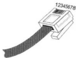
natural_image
Diagram of a USB connector with a black cable and labeled pin number 12345678 (no other text or symbols)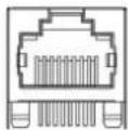
| RS485/CAN | RS485/CAN |
| Communication to inverter | Communication between battery cluster |
| PIN position | Color | Definition | |
| RS485/CAN | PIN1 | Orange/White | 485A1 |
| PIN2 | Orange | 485B1 | |
| PIN3 | Green/White | GND | |
| PIN4 | Blue | CAN1H | |
| PIN5 | Blue/White | CAN1L | |
| PIN6 | Green | GND | |
| PIN7 | Brown/White | CAN0H | |
| PIN8 | Brown | CAN0L |
3. OHS' S User Interface
3.1 Main Interface
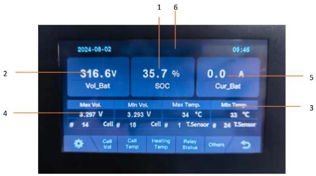
text_image
2024-08-02 316.6V Vol_Bat 35.7 % SOC 0.0 A Cur_Bat Max Vol. 3.297 V Cell # 18 Cell # 1 T.Sensor Cell Vol Cell Temp Heating Temp Relay Status Others| NO. | Description | Function |
| 1 | SOC | Display real-time SOC value of energy storage system |
| 2 | Voltage | Display real-time voltage |
| 3 | Temperature | Displays the maximum and minimum battery temperatures |
| 4 | Voltage | Displays real-time maximum and minimum cell voltages |
| 5 | Current | Display battery real-time current |
| 6 | System status | Display battery fault name (For details, see Table 6-1) |
3.2 Cell Voltage

text_image
2024-08-02 09:46 1 - 6 3294 3295 3296 3295 3296 3296 7 - 12 3296 3296 3296 3295 3296 3295 13 - 18 3296 3296 3295 3295 3296 3293 Unit: mV Cell Vol3.3 Cell Temperature

text_image
2024-08-02 09:46 1 - 6 34 34 34 34 34 34 7 - 12 34 34 34 34 34 34 13 - 18 34 34 34 34 34 34 Unit: ℃ Cell Temp3.4 Heating Temperature
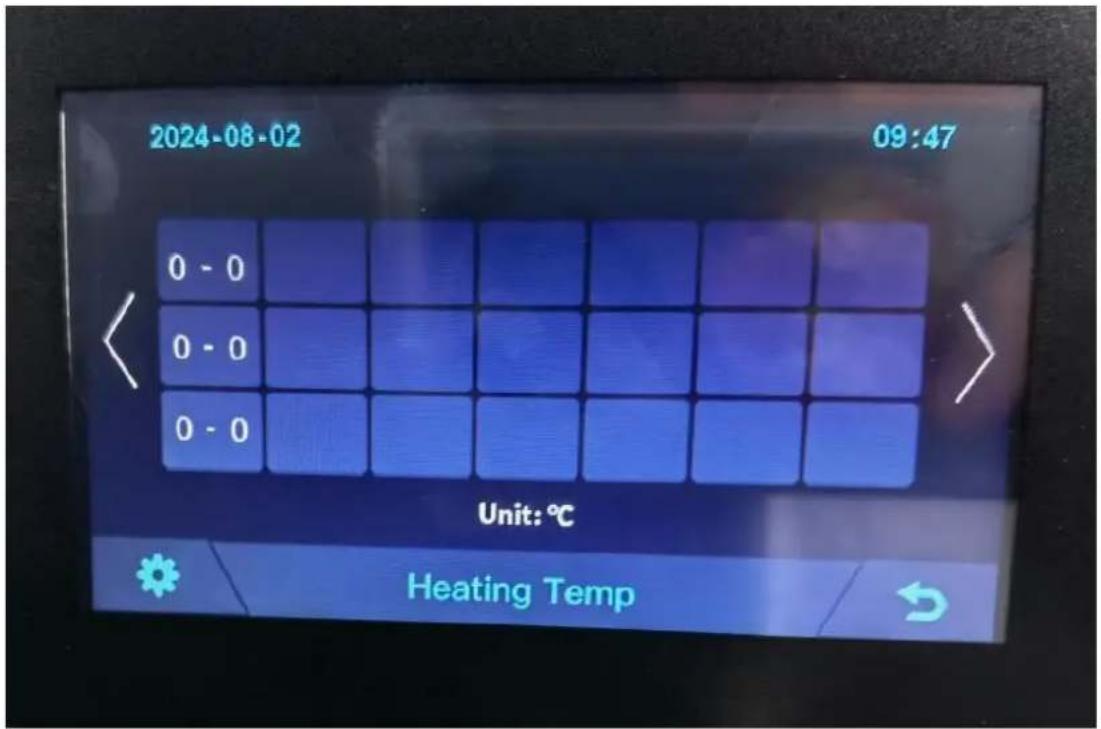
text_image
2024-08-02 09:47 0 - 0 0 - 0 0 - 0 Unit: ℃ Heating Temp3.5 Relay Status
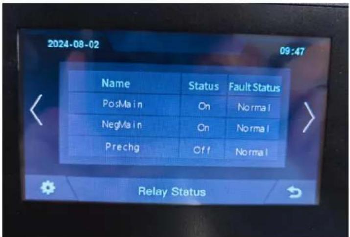
text_image
2024-08-02 09:47 Name Status Fault Status PosMain On Normal NegMain On Normal Prechg Off Normal Relay Status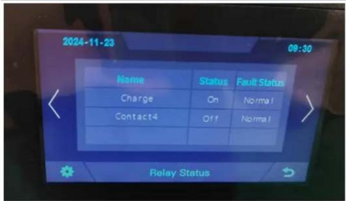
text_image
2024-11-23 09:30 Name Status Fault Status Charge On Normal Contact4 Off Normal Relay Status3.6 Other
text_image
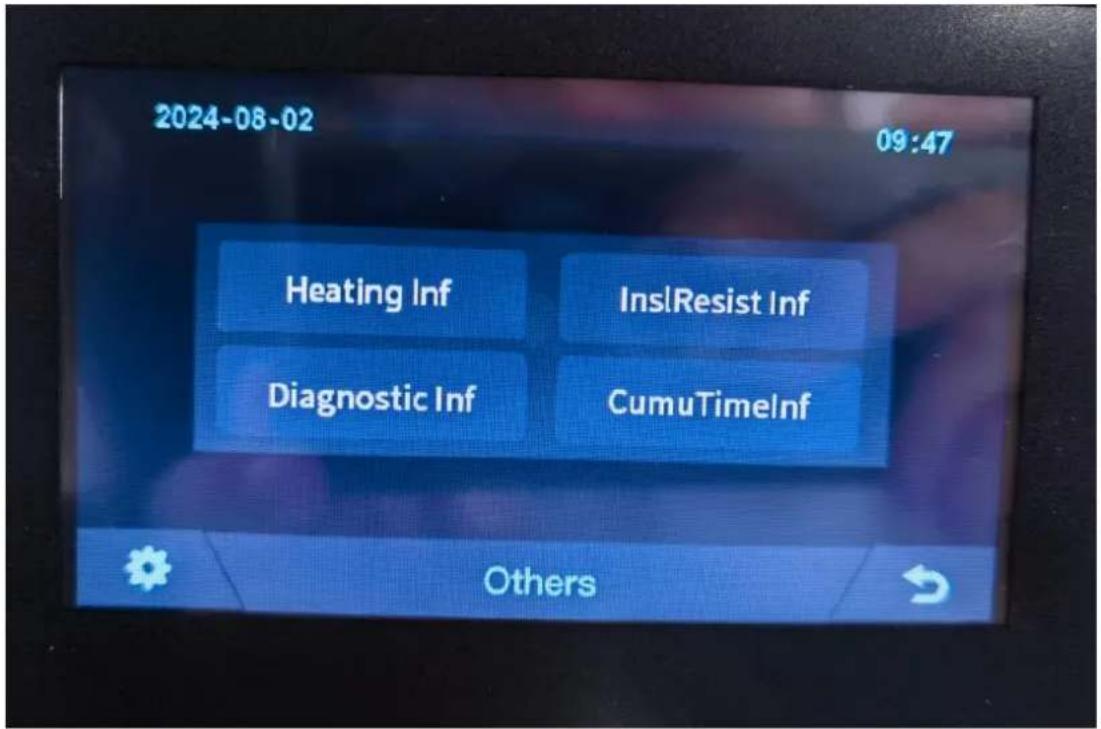
2024-08-02 09:47 Heating Inf InsI Resist Inf Diagnostic Inf CumuTimeInf Others3.6.1 Heating Information
text_image
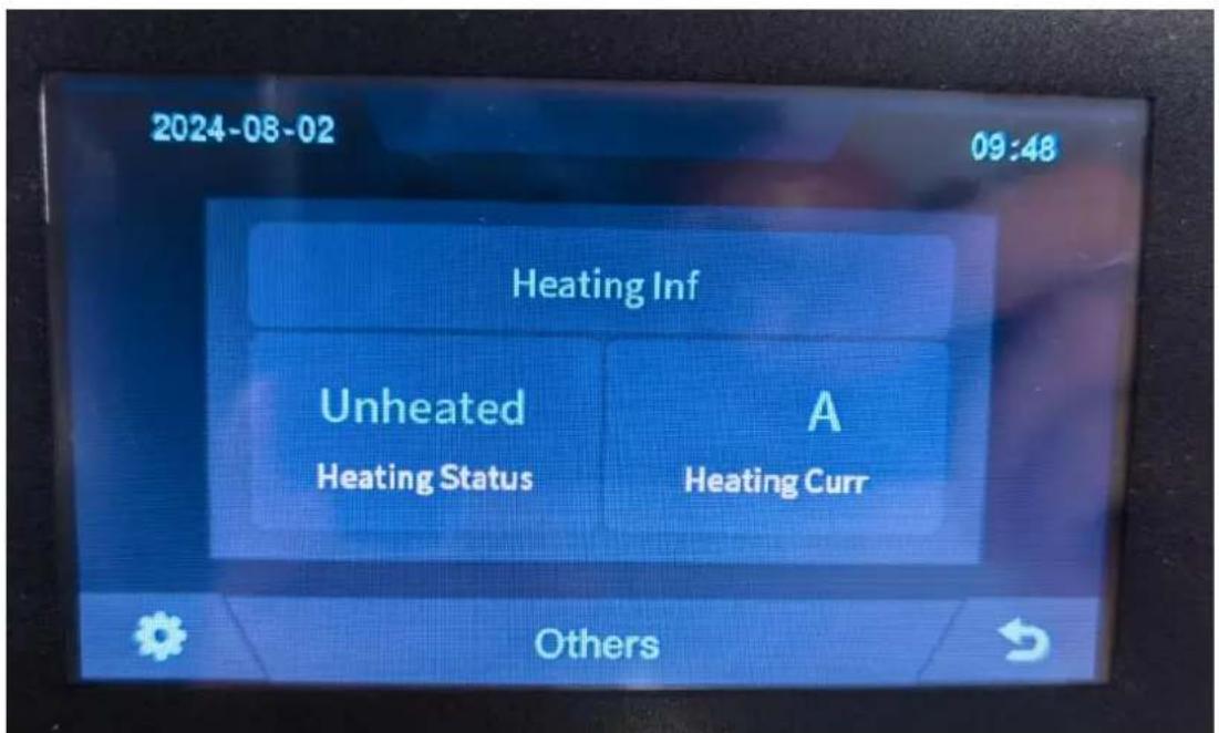
2024-08-02 09:48 Heating Inf Unheated A Heating Status Heating Curr Others3.6.2 Insulation Resistense
text_image
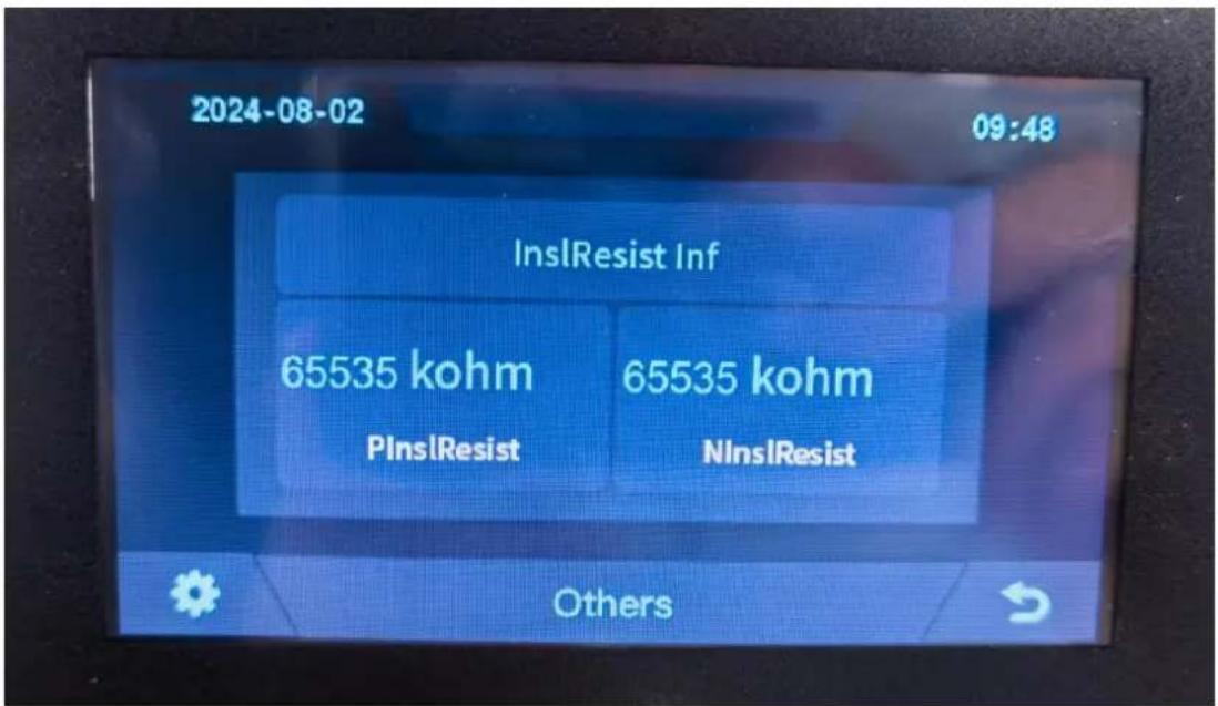
2024-08-02 09:48 InsIResist Inf 65535 kohm 65535 kohm PInsIResist NInsIResist Others3.6.3 Diagnostic Information

text_image
2024-08-02 09:48 Diagnostic Inf No fault Others3.6.4 Cumulative Time Information
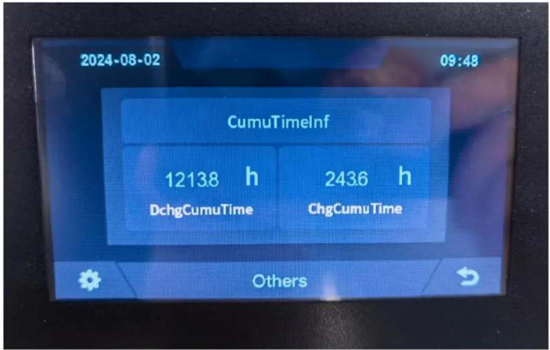
text_image
2024-08-02 09:48 CumuTimelInf 12138 h DchgCumuTime 2436 h ChgCumu Time Others3.7 Set Up
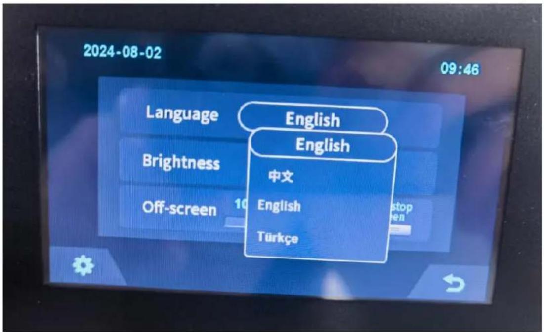
text_image
2024-08-02 09:46 Language English English Brightness 中文 English Off-screen 10 stop en Türkçe4. Xiaodan Energy Storage App
4.1 App download
4.1.1 Android version
- Enter the official website of Youdan Technology https://www.udantech.com/#/, click on the "SAAS Application" column in the top navigation bar, pull down to the mobile app application module, and you can see the mobile WeChat Mini Program and App application download.

text_image
udantech.com UDAN优旦 iBMS Hardwares PasS Platforms SaaS Applications Business Scopes About Us Contact Us
text_image
Udan live APP Online management of all new facilities
text_image
QR code with central logo and WeChat Pay icon, likely for payment or app linkingWechat mini program scan code experience

text_image
QR code with a central logo, likely linking to a digital resource or website.APP download
4.1.2 iOS version
Enter the mobile App Store, search for "Xiaodan Energy Storage", and you can download and install it.
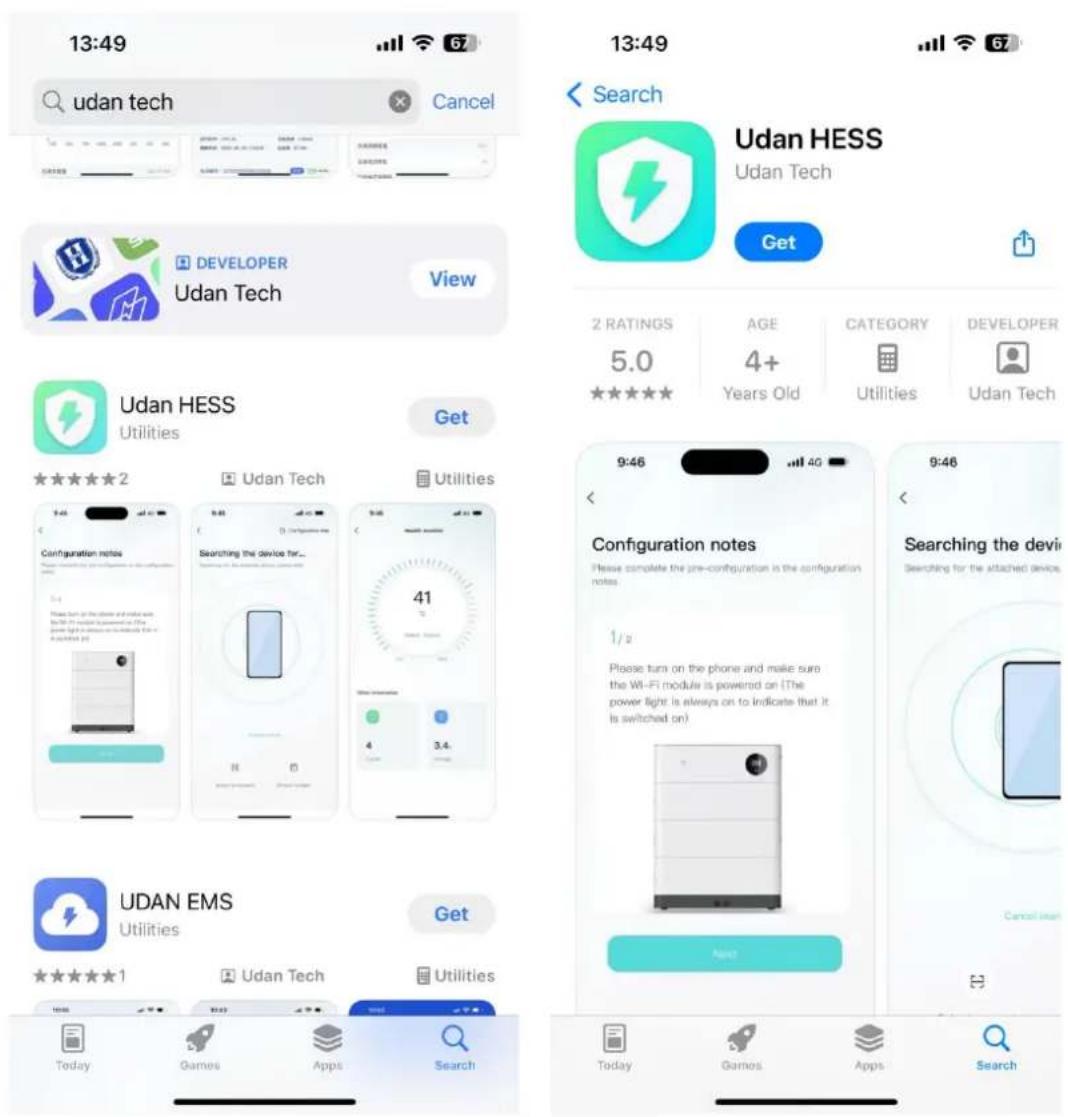
text_image
13:49 udan tech Cancel 13:49 Search Udan HESS Udan Tech Get 2 RATINGS AGE CATEGORY DEVELOPER 5.0 4+ Years Old Utilities Udan Tech Udan HESS Utilities Get ★★★★★ 2 Udan Tech Utilities Configuration notes Searching the device for... 41 Please turn on the phone and make sure the Wi-Fi module is powered on (The power light is always on to indicate that it is switched on) 9:46 Configuration notes Please complete the pre-configuration in the configuration notes. 1/2 Please turn on the phone and make sure the Wi-Fi module is powered on (The power light is always on to indicate that it is switched on) 9:46 Searching the device Searching for the attached devices Next UDAN EMS Utilities Get ★★★★★ 1 Udan Tech Utilities Today Games Apps Search Today Games Apps Search4.2. Log in and register
4.2.1 Log in
• After opening the APP, enter the login interface to log in with your account.
- Currently supports logging in through email accounts
10:24

English

Email login
Keep track of your device in real time
Please enter your email account
Please enter your password

Logit

Remember pwd
Forgot pwd


Experience login Device networking
Account registration
By logging in you are agreeing Service and Privacy
4.2.2 Register
- At the bottom of the login page, click the "Account Registration" button to enter the registration process.
- Currently, you can register with an email account. After registration, you need to go through the device verification process and enter the device SN code or device QR code for identification.
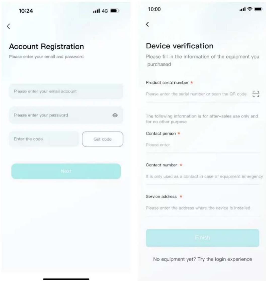
text_image
10:24 Account Registration Please enter your email and password Please enter your email account Please enter your password Enter the code Get code Next 10:00 Device verification Please fill in the information of the equipment you purchased Product serial number * Please enter the serial number or scan the QR code The following information is for after-sales use only and for no other purpose Contact person * Please enter Contact number * It is only used as a contact in case of equipment emergency Service address * Please enter the address where the device is installed Finish No equipment yet? Try the login experience4.2.3 Experience login
- At the bottom of the login page, click the "Experience Login" button to experience the app function without registration as a tourist.

text_image
Experience login Device networking Account registration4.3. Equipment distribution network
4.3.1 Overview
Device distribution network refers to connecting devices to the Cloud Computing Platform to help users obtain real-time device data information.
4.3.2 Distribution process
- Preparation before distribution: Ensure that the device is on, turn on the mobile phone Bluetooth and wireless LAN functions.
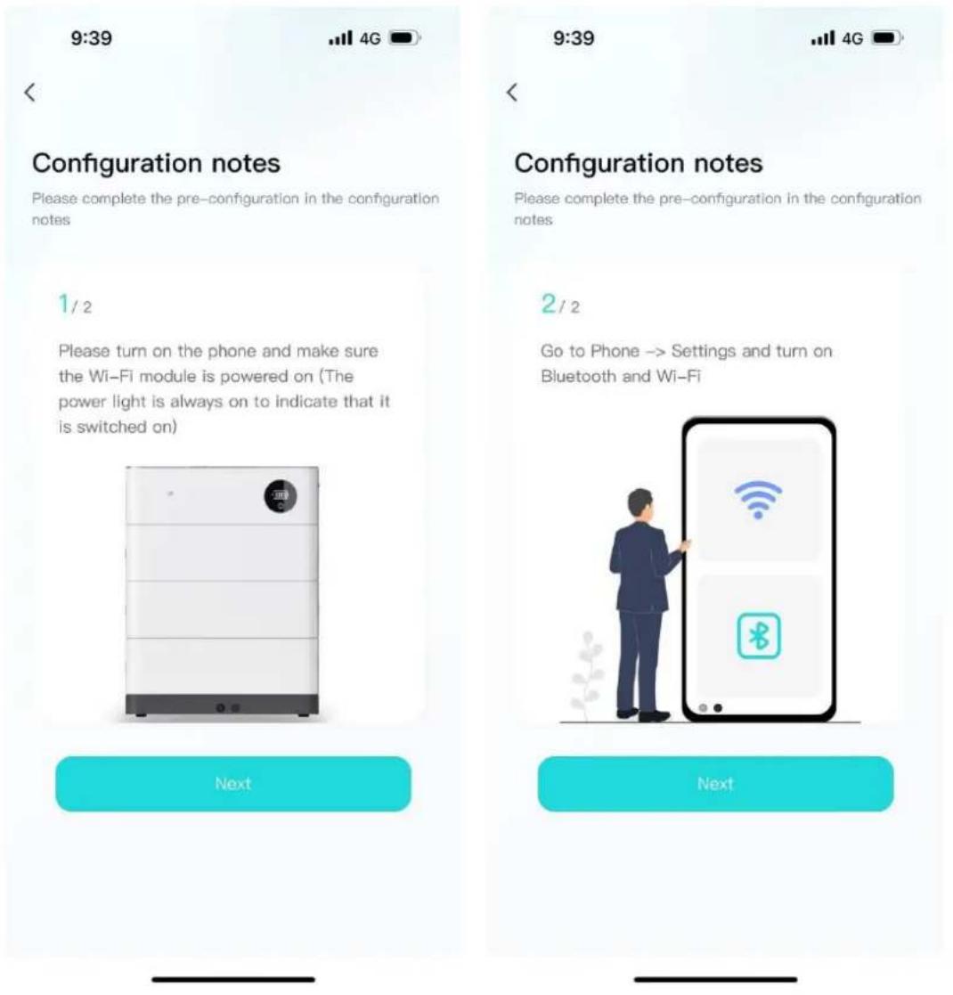
text_image
9:39 Configuration notes Please complete the pre-configuration in the configuration notes 1 / 2 Please turn on the phone and make sure the Wi-Fi module is powered on (The power light is always on to indicate that it is switched on) Next 9:39 Configuration notes Please complete the pre-configuration in the configuration notes 2 / 2 Go to Phone -> Settings and turn on Bluetooth and Wi-Fi Next- Connected devices: The current App supports Bluetooth search, device scanning, and manual input of SN code.
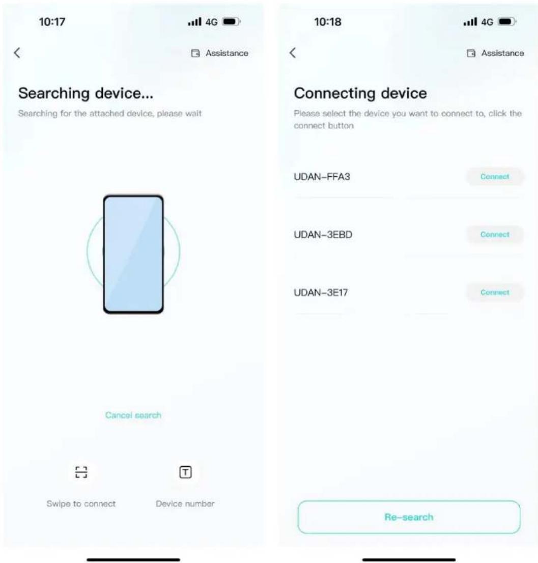
text_image
10:17 4G Assistance Searching device... Searching for the attached device, please wait Cancel search Swipe to connect Device number 10:18 4G Assistance Connecting device Please select the device you want to connect to, click the connect button UDAN-FFA3 Connect UDAN-3EBD Connect UDAN-3E17 Connect Re-search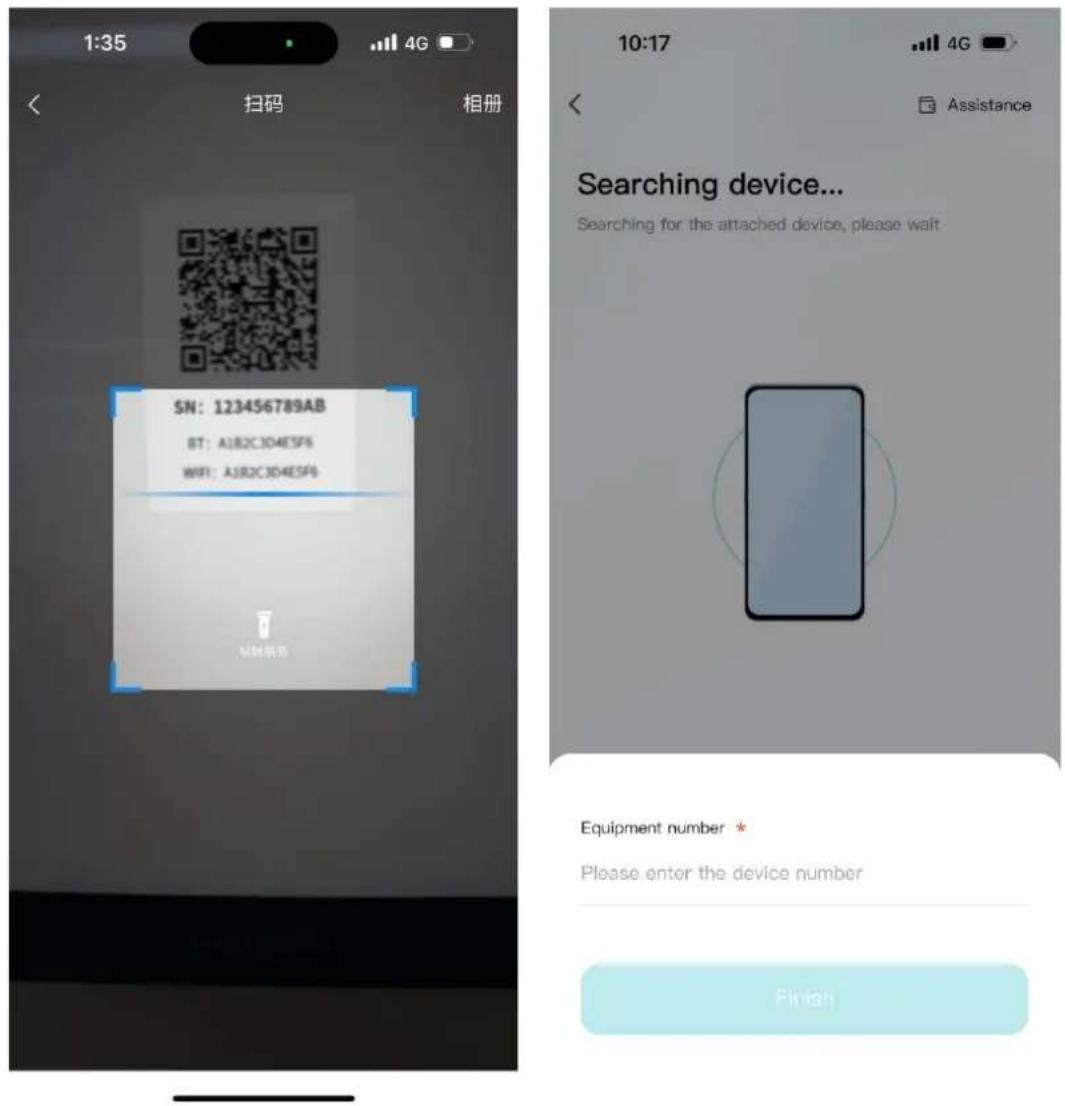
text_image
1:35 扫码 相册 SN: 123456789AB BT: AJB2C3D4E5F6 WIFI: AJB2C3D4E5F6 VMH证书 10:17 4G Assistance Searching device... Searching for the attached device, please wait Equipment number * Please enter the device number Finish- Connect to WiFi: After the device is connected, enter the WiFi connection process.
- Select the WiFi you want to use and click the "Connect" button. Enter the WiFi password and click the "Finish" button to distribute the network.
10:00


Assistance
Configure Wi-Fi
Enter the password after you connect to the Wi-Fi you want to use
UDAN-GUEST
Connect
UDAN-1
Connect
UDAN-2
Connect

text_image
10:00 < Assistance Configure Wi-Fi Enter the password after you connect to the Wi- Fi you want to use UDAN-GUEST Connect UDAN-1 Connect UDAN-2 ConnectWi-Fi Password *
Please enter the wireless network password
Finish

text_image
In the distribution network ... Help the device establish a network connection. This process may take a few minutes. Do not exit the app until the configuration is complete. Bluetooth connection completed Mobile phone transmits Wi-Fi information to Bluetooth Devices connect to Wi-Fi Data connection between BMS and cloud platform Configuration succeeded! Equipment: UDAN - FFC3 Wi-Fi: UDAN-GUEST Return Continue to distribute the network4.4. App page
4.4.1 Equipment
The device homepage is used to display the currently managed device information.
9:20

UDAN-057A

Total battery energy: 20.48kWh

20.3%
Charging...

natural_image
3D rendered rectangular tray with a cyan top and dark gray side, no text or symbols visibleCurrent power
1.6kW
Expected full
10 h 33 m
Device information
(Today: 2023-10-23)
View details
Electricity (capacity)


• total chg
2.8 kWh
Charging time

0 h
Discharged 7.2 h
- total dChg
0.2 kWh
Health monitor

Normal
Battery temper 21 °C

Device

Mine
- The top area displays the device name, battery energy, and message entry.
UDAN-057A


Total battery energy: 20.48kWh

- Middle area: Displays the current battery charging and discharging status, battery percentage, current power, and estimated full time.

bar
| Category | Value | |---|---| | Current power | 1.6 kW | | Expected full | 10 h 33 m | | Charging... | 20.3 % |- The bottom area: Displays the device battery, charging time, and health check overview data of the day in the form of a card. You can click the corresponding card to view the details.

pie
| Category | Value | | :--- | :--- | | Electricity (capacity) | > | | Charging time | > | | 0 h | Discharged 7.2 h | | Health monitor | > | | Normal | Battery temper 21 °C | | Total chg | 2.8 kWh | | Total dChg | 0.2 kWh |4.4.2 Data details
Display the data details of the current device, and view the battery, charging and discharging power, and charging and discharging time data separately, and support time filtering.

pie
| Metric | Value | | :--- | :--- | | Cumulative change (kWh) | 1449 | | Cumulative discharge (kWh) | 1395.9 | | Day | Month | | Year | Year | | Before | 2023-10-23 (Q) | | After > | | | Charging time day (kWh) | 2.9 | | Discharge time day (kWh) | 0.2 | | Current remaining (kWh) | 4.2 | Unit: kWh
line
| Date | Peak change power (kW) | Peak discharge power (kW) | |---|---|---| | 2015-01 | 0.0 | 0.0 | | 2016-01 | 0.0 | 0.0 | | 2017-01 | 0.0 | 0.0 | | 2018-01 | 0.0 | 0.0 | | 2019-01 | 0.0 | 0.0 | | 2020-01 | 0.0 | 0.0 | | 2021-01 | 0.0 | 0.0 | | 2022-01 | 0.0 | 0.0 | | 2023-01 | 0.0 | 0.0 | | 2023-10-23 08:25:01 | 2.16 kw | 0.05 kw |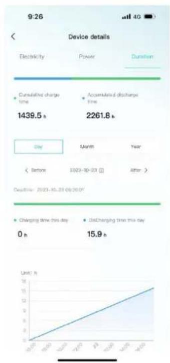
line
| Period | Charging Time (h) | Discharging Time (h) | |---|---|---| | Oct-23 | 0 | 15.9 | | Nov-23 | 10 | 16.8 | | Dec-23 | 20 | 17.7 | | Jan-24 | 30 | 18.6 | | Feb-24 | 40 | 19.5 | | Mar-24 | 50 | 20.4 | | Apr-24 | 60 | 21.3 | | May-24 | 70 | 22.2 | | Jun-24 | 80 | 23.1 | | Jul-24 | 90 | 24.0 | | Aug-24 | 100 | 24.9 | | Sep-24 | 110 | 25.8 | | Oct-24 | 120 | 26.7 | | Nov-24 | 130 | 27.6 | | Dec-24 | 140 | 28.5 | | Jan-25 | 150 | 29.4 | | Feb-25 | 160 | 30.3 | | Mar-25 | 170 | 31.2 | | Apr-25 | 180 | 32.1 | | May-25 | 190 | 33.0 | | Jun-25 | 200 | 33.9 | | Jul-25 | 210 | 34.8 | | Aug-25 | 220 | 35.7 | | Sep-25 | 230 | 36.6 | | Oct-25 | 240 | 37.5 | | Nov-25 | 250 | 38.4 | | Dec-25 | 260 | 39.3 | The chart displays a line graph of daily changes in electricity and power consumption over a week, with a secondary axis for duration. The data is already in English.4.4.3 Mine
My page allows users to view my devices, add devices, configure WiFi, software updates, after-sales services, problem feedback, app settings.
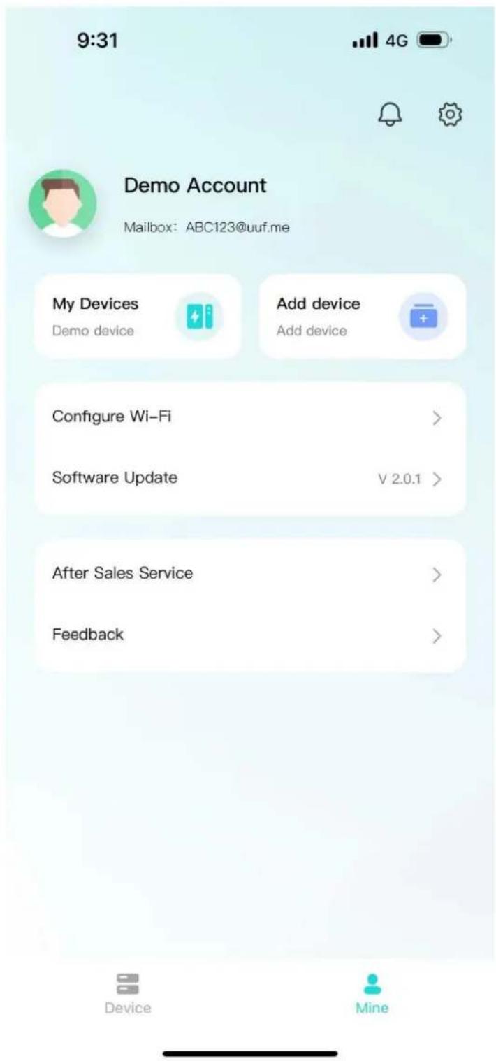
text_image
9:31 4G Demo Account Mailbox: ABC123@uuf.me My Devices Add device Add device Configure Wi-Fi > Software Update V 2.0.1 > After Sales Service > Feedback > Device Mine- Click "My Devices" to enter Facility Management. You can view all devices managed under the current account, switch devices displayed on the homepage, unbind devices, and other operations.
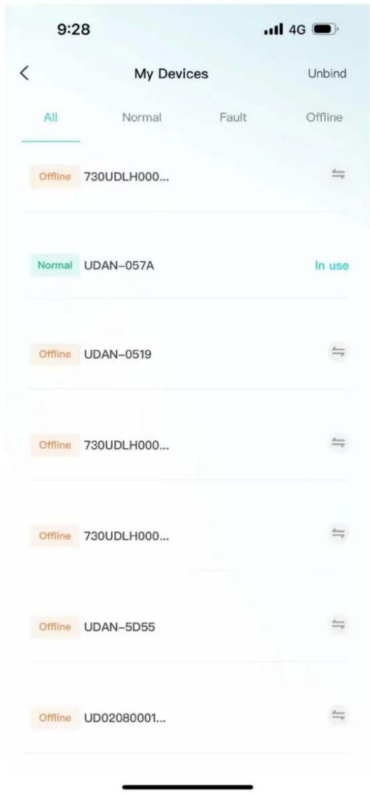
text_image
9:28 My Devices Unbind All Normal Fault Offline Offline 730UDLH000... Normal UDAN-057A In use Offline UDAN-0519 Offline 730UDLH000... Offline 730UDLH000... Offline UDAN-5D55 Offline UD02080001...- Click "Add Device" to enter the code scanning page.
- Click "Equipment Distribution Network" to enter the equipment distribution network
process.
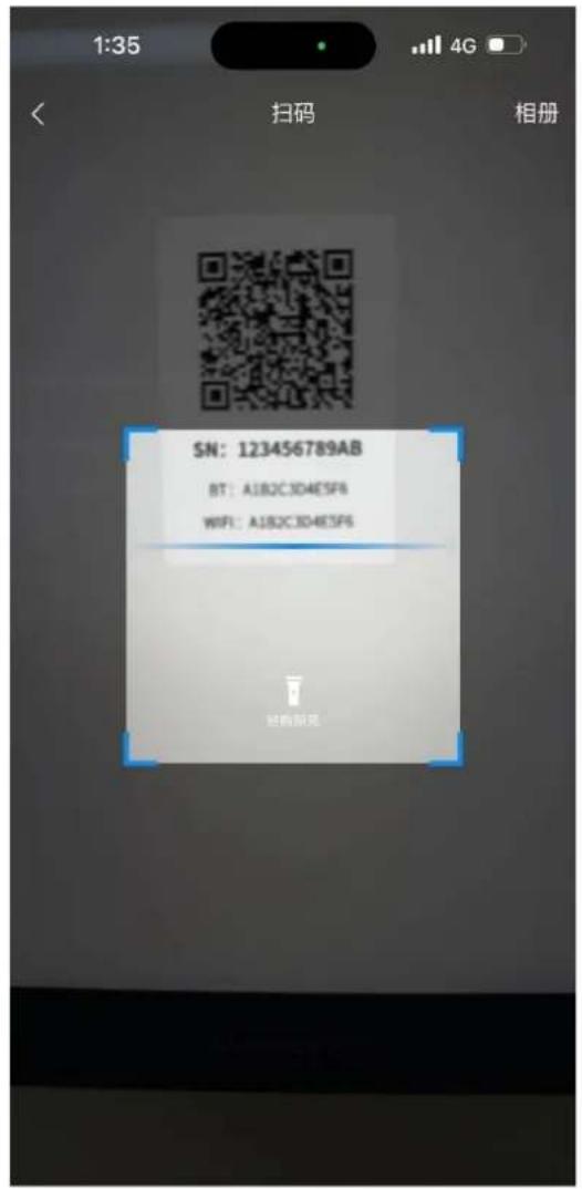
text_image
1:35 4G < 扫码 相册 SN: 123456789AB BT: A1B2C3D4E5F6 WIFI: A1B2C3D4E5F6 扫码解充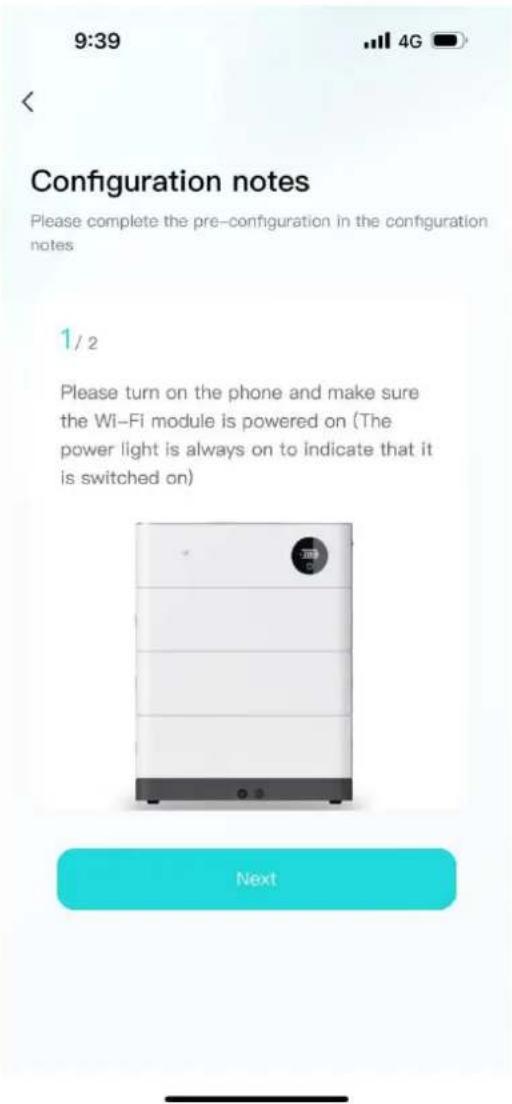
text_image
9:39 Configuration notes Please complete the pre-configuration in the configuration notes 1 / 2 Please turn on the phone and make sure the Wi-Fi module is powered on (The power light is always on to indicate that it is switched on) Next• After clicking "software update", it will enter the version detection. If there is a new version, it will be updated.
- Click "after-sales services" and enter the after-sales services page to display the after-sales services declaration of the current supplier.
9:28


After Sales Service
After-sales service is determined by the actual supplier policy
- The software and hardware provided by the Seller are of legal origin and property rights.
- The product equipment and spare parts during the after-sales period are all original and genuine.
- The specific content and maintenance scope of the product after-sales shall be negotiated between the buyer and the seller and reflected in the contract.
- Click "Feedback" to enter the feedback page. You can enter the current problem that needs feedback and submit it.
9:28


Feedback
Please fill in the details of the problem you are experiencing
Title of the problem ★
Please enter the title of the problem
Detailed description ★
Please provide a detailed description of the problem encountered
Upload an image

Upload up to three images, each up to 10M in size
Submit
4.4.4 Message
Click on the device or my page, the message icon above, you can enter the inbox page
to view the current notification or chat history.

text_image
9:28 System information 2023-10-22 Alarm notification 22:13 SOC too low alarm, The battery is low, please charge the battery in time. View details > 2023-10-22 Alarm notification 20:38 SOC too low alarm, The battery is low, please charge the battery in time. View details > 2023-10-22 Alarm notification 16:54 SOC too low alarm, The battery is low, please charge the battery in time. View details > 2023-10-214.4.5 App settings
- Click My Pages - Settings icon in the upper-right corner to enter the App Settings
page.
- Settings page support: language switching, Privacy Policy, cache cleaning, personal information, account and security.
9:28


Settings
Language Switch
English >
Privacy Policy
Cache Cleanup
4.0MB >
Personal Information
Account and Security
Logout
5. Installation and Configuration
5.1 Preparation for installation
5.1.1 Safety Requirement
This system can only be installed by personnel who have been trained in the power supply system and have sufficient knowledge of the power system.
The safety regulations and local safety regulations listed below should always be followed during the installation.
- All circuits connected to this power system with an external voltage of less than 500V must meet the SEHV requirements defined in the IEC60950 standard.
- If operating within the power system cabinet, make sure the power system is not charged. Battery devices should also be switched off.
- Distribution cable wiring should be reasonable and has the protective measures to avoid touching these cables while operating power equipment.
- when installing the battery system, must wear the protective items below:
 |  |  |
| The isolation gloves | Safety goggles | Safety shoes |
5.1.2 Environmental requirements
Charging temperature range is ^ 0\~+45℃,
Discharging temperature range is -10 \~+55°C
Storage temperature: 0℃\~ +35℃
Relative humidity: 5% \~ 85%RH
Elevation: no more than 2000m
Operating environment: Indoor installation, sites avoid the sun and no wind, no conductive dust and corrosive gas.
And the following conditions are met:
• Installation location should be away from the sea to avoid brine and high humidity environment.
- The ground for product arrangement shall be flat and level.
- No flammable explosive materials near the installation site.
• The optimal ambient temperature is°C1530°C
- Keep away from dust and messy zones
5.1.3 Tools and data
Tools and meters that may be used are shown in table 5-1.
Table 5-1 Tool instrument
| NAME | |
| Screwdriver (Slotted、Phillips) | Multimeter |
| Torque wrench | Clamp current meter |
| Diagonal pliers | Insulation tape |
| Pointed nose pliers | Temperature meter |
| Pliers to hold the wire | Anti-static bracelet |
| Stripping pliers | Cable tie |
| Electric drill | Tape measure |
5.1.4 Technical preparation
Electrical interface check
Devices that can be connected directly to the battery can be user equipment, power supplies, or other power supplies.
- Confirm whether the user's PV power generation equipment, power supply or other power supply equipment has a DC output interface, and measure whether the DC power output voltage meets the voltage range requirements in Table 2-2.
- Confirm that the maximum discharge current capability of the DC power interface of the user's photovoltaic power generation equipment, power supply or other power supply equipment should be higher than the maximum charging current of the products used in
Table 2-2.
If the maximum discharge capacity of the DC power interface of the user's photovoltaic power generation equipment is less than the maximum charging current of the products used in Table 2-2, the DC power interface of the user's photovoltaic power generation equipment shall have a current limiting function to ensure the normal operation of the user's equipment.
- Verify that the maximum operating current of the battery-powered user equipment (inverter DC input) should be less than the maximum discharge current of the products used in Table 2-2.
The security check
● Firefighting equipment should be provided near the product, such as portable dry powder fire extinguisher.
● Automatic fire fighting system shall be provided for the case where necessary.
● No flammable, explosive and other dangerous materials are placed beside the battery.
5.1.5 Unpacking inspection
- When the equipment arrives at the installation site, loading and unloading should be carried out according to the rules and regulations, to prevent from being exposed to sun and rain.
● Before unpacking, the total number of packages shall be indicated according to the shipping list attached to each package, and the case shall be checked for good condition. - In the process of unpacking, handle with care and protect the surface coating of the object.
- Open the package, the installation personnel should read the technical documents, verify the list, according to the configuration table and packing list, ensure objects are complete and intact, if the internal packing is damaged, should be examined and recorded in detail.
Packing list is as follows:
| Item | Specification | Quantity | Figure |
| Battery module | 51.2V/100AH5.12Kwh | N |  |
| High voltage battery cluster control box | 50A | 1 |  |
| Battery module base | 1 |  | |
| Positive Cable to inverter | Red/8 AWG/L2000mm | 1 |  |
| Negative Cable to inverter | Black/8 AWG/L2000mm | 1 |  |
| Communication Cable to inverter | L2000mm | 1 |  |
| Communication Cable between batteries | L1000mm | 1 |  |
| Earthing wrie | L2000mm | 1 |  |
| 120 Ω terminal resistance | 1 |  | |
| RJ45 waterproof connector | 3 |  | |
| Screw | M4*16 | 5 |  |
| User Manual | 1 |
5.2 Equipment installation
5.2.1 Installation Steps
Step 1 Mechanical Installation
(1) Installation step:

natural_image
Exterior view of a white industrial battery unit labeled V-TAC, with no visible text or symbols on the body.Step 4: Install side fastening screws
Step 3: Install the High voltage battery cluster control box
Step 2: Install the Battery module
Step 1: Install the Battery module base
Step 2 Electrical installation
(1) Connect with inverter
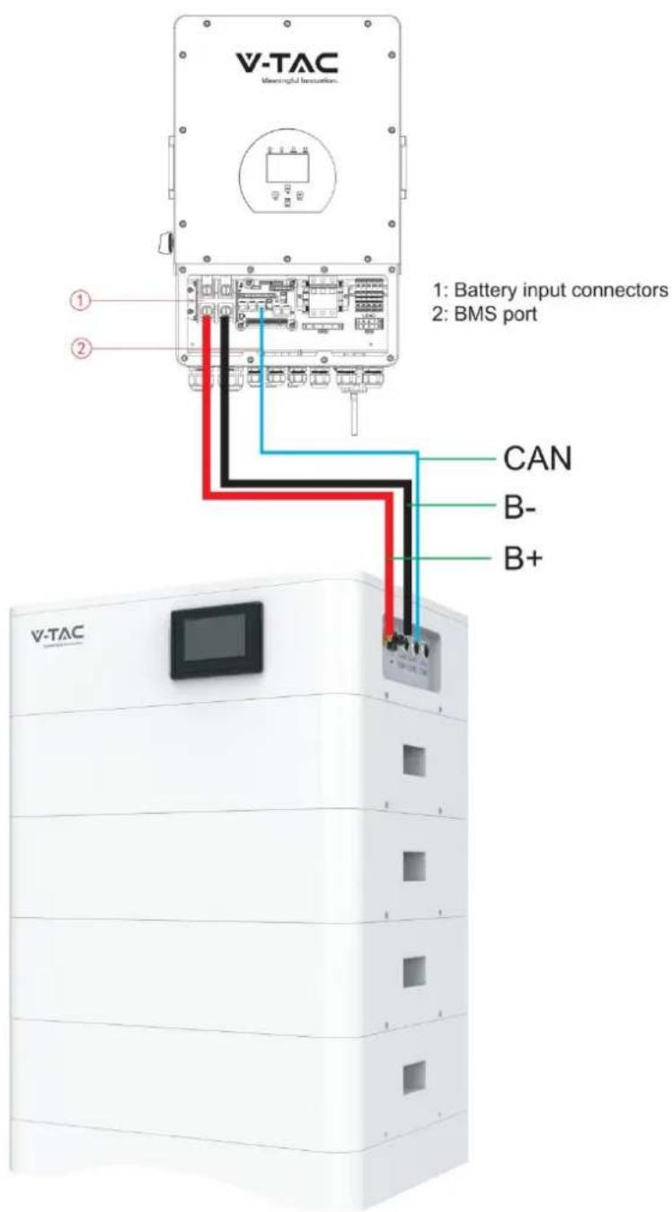
text_image
V-TAC Meaningful Innoation. 1: Battery input connectors 2: BMS port CAN B- B+5.2.2 Battery parameter settings on the inverter
If your inverter do not have communication function with OHS-100 battery pack, please set inverter follow next data.
Max Charging(module) Voltage: 56.0V*N
Shut Down(cut off) Voltage: 49.0V*NSOC20%)
Shut Down(cut off) SOC: 20%
Restart Voltage: 51.2V*N
Max Charge Current: 50A
Max Discharge Current: 50A
6. Installation and Configuration
6.1 Battery system usage and operation instructions
After completing the electrical installation, follow these steps to start the battery system.
- Open the BMS on/off, wait the screen open and show battery with normal status.
- After the LCD screen show battery with normal status, open the air switch.

-
After pressing the power button, if the LCD screen show battery with ALM sta please refer to the "6.2 Alarm description and processing". If the failure cannot be eliminated, please contact the dealer timely.
-
Use a voltmeter to measure whether the voltage of the circuit breaker battery access terminal is higher than 48V^N , and check whether the voltage polarity is consistent with the inverter input polarity. If the circuit breaker battery input terminal has a voltage output and is greater than 48V^N , then the battery begun to work normally.
- After confirming that the battery output voltage and polarity are correct, turn on the inverter, close the circuit breaker.
- Check if the indicator of the inverter and battery connection (communication indicator and battery access status indicator) is normal. If it is normal, successfully complete the connection between the battery and the inverter. If the indicator light is abnormal, please refer to the inverter manual for the cause
6.2 Alarm description and processing
When protection mode is activated or system failure occurred, the alarm signal will be given through the system status on the LCD. The network management can query the specific alarm categories.
If the fault such as single cell over voltage, charging over-current, under-voltage protection, high-temp protection and other abnormalities which affects the output, please deal with it according to Table 6-1.
Table 6-1 Main alarm and Protection
| Statue | Alarm category | system status | Processing |
| Charge state | Over-current | Over-current during slow charging | Stop charging and find out the cause of the trouble |
| Over-voltage | Cell voltage too high in charge | Stop charging | |
| High temp | Temperature too high | Stop charging | |
| Low temp | Temperature too low | Stop charging | |
| Discharge state | Over-current | Continuous over-current | Stop discharging |
| High temp | Temperature too high | Stop discharging | |
| Low temp | Temperature too low | Stop discharging | |
| Low-voltage | Cell voltage too low in discharge | Stop discharging |
6.3 Analysis and treatment of common faults
Analysis and treatment of common faults in the Table 6-2:
Table 6-2 Analysis and treatment of common faults
| No. | Fault phenomenon | Reason analysis | Solution |
| 1 | The indicator does not respon after the power on Total voltage lower than 40V*N Check the total voltage | Total voltage lower than 40V*N | Check the total voltage |
| 2 | No DC output | Battery data status is abnormal. Battery gets into over-discharged protection | Read the battery information on the monitor. |
| 3 | The DC power supply time is too short | Battery capacity become smaller | Storage battery replacement or add more modules |
| 4 | The battery can't be fully charged to 100% | Charging voltage is too low | Adjust charging voltage at 57V*N |
| 5 | The power cable sparks once power on and ALM light RED | Power connection short-circuit | Turn off the battery, check the cause of th short circuit |
| 6 | Communication fault | The battery type of the inverter is wrong/Communication cable used incorrectly/The communication cable is incorrectly connected at the battery communication port or the inverter communication port/The battery firmware version is too low to support t inverter | Check these possible causes one by one |
If you need any technical help or have any question, please contact the dealer in time.
7 Battery Module Storage
①To ensure the battery service life, the storage temperature shall be kept between 0°C\~35°C.
②The battery shall be cycled at least once every 6 months.
8 Maintenance

Warning! Improper decommissioning may cause damage to the equipment and/or battery inverter.
Before maintenance, ensure that OHS-100 is decommissioned according to relevant provisions.

Note: All maintenance work shall comply with local applicable regulations and standards.
The USB-CAN port of OHS has the functions of upgrading firmware and recording battery data, which can be used as an auxiliary tool.
To ensure safe operation, all plug connections must be checked. If necessary, relevant operators shall press them back into place at least once a year.
The following inspection or maintenance must be carried out once a year:
- General visual inspection
- Check all tightened electrical connections. Check the tightening torque according to the values in the following table. Loose connections must be retightened to the specified torque.
| Connection mode | Tightening torque |
| high-voltage BMS box grounding | 4.5Nm |
| Fixing the lug of the high-voltage BMS | 1.2Nm |
| Fixing the lug of the battery module | 1.2Nm |
- Using the monitoring software, check whether the SoC, SoH, battery voltage and temperature of the battery module are abnormal.
- Shut down and restart OHS-100 once a year.
Note: If the system is installed in a polluted environment, maintenance and cleaning must be carried out at short intervals.
Note: Clean the battery rack with a dry-cleaning cloth. Ensure that no moisture comes into contact with the battery connections. Do not use solvents.

IMPORTANT NOTES:
- This product contains battery type rechargeable.
- Electrical and electronic equipment that has become waste is known as old equipment /device. Old devices must not be disposed of with other household waste.
- Owners of old devices at the end of its service life must return the device by taking them to the collection points set up by public waste disposal authorities or distributors. This return does not entail any costs for you.
- Owners of old devices have an obligation to remove accessible batteries / rechargeable batteries as well as non-destructively removable lamps from the old device prior to return. This does not apply if old devices are being prepared for reuse with the participation of a public law firm.
- Battery removal warning: The battery contained in this product must be removed only by professional personnel only. The battery must never be removed by the end user, if not removed correctly it could damage the battery which could cause fire.
- Batteries removed from an old electronic device should be disposed of separately. This return of battery does not entail any costs for you and the user is obliged to return the battery.
- Please make sure that this product is not powered on when removing the battery. Fire hazard! Avoid short-circuiting the contacts of a detached battery. Do not incinerate the battery. Please handle the battery with Caution!
- If electrical appliances or batteries are disposed of in landfills or dumps, hazardous substances can leak into the groundwater and get into the food chain, damaging your health and well-being.

- The symbol of "Crossed rubbish bins" indicates that this product should not be disposed of with other household wastes and must be collected separately from unsorted municipal
- Please use the link below to view the online directory of the collection and return points:https://www.ear-system.de/ear-verzeichnis/sammel-und-ruecknahmestellen
Legal Statement
The information contained in the document is the property of V-TAC Europe Ltd.
All information shall not be published in whole or in part without the written permission of V-TAC Europe Ltd.