UC-MM30-Z - Video Conferencing System Crestron - Free user manual and instructions
Find the device manual for free UC-MM30-Z Crestron in PDF.

User questions about UC-MM30-Z Crestron
0 question about this device. Answer the ones you know or ask your own.
Ask a new question about this device
Download the instructions for your Video Conferencing System in PDF format for free! Find your manual UC-MM30-Z - Crestron and take your electronic device back in hand. On this page are published all the documents necessary for the use of your device. UC-MM30-Z by Crestron.
USER MANUAL UC-MM30-Z Crestron
Crestron Flex Unified Communications Solutions
Original Instructions
The U.S. English version of this document is the original instructions. All other languages are a translation of the original instructions.
Crestron product development software is licensed to Crestron dealers and Crestron Service Providers (CSPs) under a limited nonexclusive, nontransferable Software Development Tools License Agreement. Crestron product operating system software is licensed to Crestron dealers, CSPs, and end-users under a separate End-User License Agreement. Both of these Agreements can be found on the Crestron website at www.crestron.com/legal/software_license_agreement.
The product warranty can be found at www.crestron.com/warranty.
The specific patents that cover Crestron products are listed at www.crestron.com/legal/patents.
Certain Crestron products contain open source software. For specific information, visit www.crestron.com/opensource.
Crestron, the Crestron logo, Crestron Fusion, Crestron Toolbox, XiO Cloud, and Smart Graphics are either trademarks or registered trademarks of Crestron Electronics, Inc., in the United States and/or other countries. ASUS is either a trademark or registered trademark of ASUSTeK Computer Inc. in the United States and/or other countries. Avaya Aura is either a trademark or registered trademark of Avaya, Inc. in the United States and/or other countries. Bluetooth is either a trademark or registered trademark of Bluetooth SIG, Inc. in the United States and/or other countries. Cisco and Cisco Webex are either trademarks or registered trademarks of Cisco Technology, Inc. in the United States and/or other countries. GotoMeeting is either a trademark or registered trademark of Citrix Online, LLC in the United States and/or other countries. Dell is either a trademark or registered trademark of Dell Inc. in the United States and/or other countries. DECT is either a trademark or a registered trademark of the European Telecommunications Standards Institute in the United States and/or other countries. Android is either a trademark or registered trademark of Google Inc. in the United States and/or other countries. Jabra and PanaCast are trademarks of GN Audio A/S in the United States and/or other countries. HDMI and the HDMI logo are either trademarks or registered trademarks of HDMI Licensing LLC in the United States and/or other countries. Huddy IQ is either a trademark or registered trademark of Huddy AS in the United States and/or other countries. Lenovo and ThinkSmart are either trademarks or registered trademarks of Lenovo in the United States and/or other countries. Microsoft, Microsoft Exchange Server, Microsoft Intune, Microsoft Teams, Microsoft 365, Outlook, Skype, and Windows are either trademarks or registered trademarks of Microsoft Corporation in the United States and/or other countries. Mitel is either a trademark or registered trademark of Mitel Networks Corporation in the United States and/or other countries. ShoreTel is either a trademark or registered trademark of ShoreTel, Inc. in the United States and/or other countries. Shure and IntelliMix are either trademarks or registered trademarks of Shure Incorporated or Shure Acquisition Holdings, Inc. in the United States and/or other countries. Slack is either a trademark or registered trademark of Slack Technologies, Inc. in the United States and/or other countries. USB Type-C is either a trademark or registered trademark of USB Implementers Forum, Inc. in the United States and/or other countries. DisplayPort is either a trademark or registered trademark of Video Electronics Standards Association in the United States and/or other countries. Zoom and Zoom Rooms are either trademarks or registered trademarks of Zoom Video Communications, Inc. in the United States and/or other countries. Other trademarks, registered trademarks, and trade names may be used in this document to refer to either the entities claiming the marks and names or their products. Crestron disclaims any proprietary interest in the marks and names of others. Crestron is not responsible for errors in typography or photography.
HDMI
©2024 Crestron Electronics, Inc.
Contents
What's New?...viii
March 29, 2024 (Doc ID: 9132E) viii
February 26, 2024 (Doc ID: 9132D).viii
September 19, 2022 (Doc ID: 9132C). ix
April 29, 2022 (Doc ID: 9132B). ix
October 5, 2021 (Doc ID: 9132A). ix
Overview 1
Intended Audience 2
System Hardware..3
UC Engine Bracket Assembly...4
Control Device..7.
Camera 10
Intelligent Videobar..12
UC-PR 14
HDMI® over CATx Receiver 15
Extension Microphone Pod 16
Room Design
Small Room Application.... 18
Medium Room Application 20
Large Room Application 23
Custom Room Application 26
Microsoft Teams® Rooms Solution
Features 27
UC-B30-T and UC-B31-T Series Features 28
UC-BX30-T and UC-BX31-T Series Features 32
UC-MM30-TA and UC-MM30-TA-I Features 36
UC-MM30-T and UC-MMX30-T Series Features 38
UC-C100-T and UC-CX100-T Series Features 41
UC-M50-T and UC-MX50-T Features 45
UC-M50-T-UPGRD and UC-MX50-T-UPGRD Features 48
UC-M70-T and UC-MX70-T Features 51
UC-M70-NC-T and UC-MX70-NC-T Features 54
Specifications and Dimension Drawings.
Tabletop Conferencing Device Specifications 58
Tabletop Conferencing Device Dimension Drawing 59
Mini Tabletop Conferencing Device Specifications 60
Mini Tabletop Conferencing Device Dimension Drawing 61
Tabletop and Wall Mount Touch Screen Specifications 62
Tabletop Touch Screen Dimension Drawing 63
Wall Mount Touch Screen Dimension Drawing 64
Smart Soundbar and Camera Specifications 66
UC-SB1-CAM-FLEX Dimension Drawing 67
Camera Specifications 69
UC Engine Bracket Assembly Specifications.70
UC Engine Bracket Assembly Dimension Drawing 71
UC Presentation Transmitter Specifications 74
UC Presentation Transmitter Dimension Drawing 75
Microphone Pod Specifications 76
Microphone Pod Dimension Drawing 76
Installation and Connections.77
Installing Microsoft Teams Rooms Solutions Powered by Dell UC Engine 82
Installing Microsoft Teams Rooms Solutions Powered by ASUS UC Engine.218......
UC-MM30-TA and UC-MM30-TA-I Installation 219
Configuration 222
Microsoft Teams Rooms Deployment and Setup 222
Microsoft Teams Rooms Software Updates 225
Crestron Settings App 226
Switching from Microsoft Teams Rooms to Zoom Rooms 237
Operation 247
Zoom Rooms® Solution 248
Features 248
UC-B30-Z and UC-B31-Z Series Features 249
UC-BX30-Z and UC-BX31-Z Series Features 252
UC-B70-A-Z and UC-B70-A-Z-I Features 255
UC-MM30-Z and UC-MMX30-Z Series Features 258
UC-C100-Z and UC-CX100-Z Series Features 261
UC-M50-Z and UC-MX50-Z Features 264
UC-M50-Z-UPGRD and UC-MX50-Z-UPGRD Features 267
UC-M70-Z and UC-MX70-Z Features 269
UC-M70-NC-Z and UC-MX70-NC-Z Features 272
Specifications and Dimension Drawings 274
Tabletop Conferencing Device Specifications.275
Tabletop Conferencing Device Dimension Drawing 276
Mini Tabletop Conferencing Device Specifications 277
Mini Tabletop Conferencing Device Dimension Drawing 278
Tabletop and Wall Mount Touch Screen Specifications 279
Tabletop Touch Screen Dimension Drawing 280
Wall Mount Touch Screen Dimension Drawing 281
Crestron Videobar 70 Specifications.... 283
Crestron Videobar 70 Dimension Drawing 284
Smart Soundbar and Camera Specifications 285
UC-SB1-CAM-FLEX Dimension Drawing 286
Camera Specifications 288
UC Engine Bracket Assembly Specifications 289
UC Engine Bracket Assembly Dimension Drawing 290
UC Presentation Transmitter Specifications 293
UC Presentation Transmitter Dimension Drawing 294
Microphone Pod Specifications 295
Microphone Pod Dimension Drawing 295
Installation and Connections 296
Installing Zoom Rooms Solutions Powered by Dell UC Engine 300
Installing Zoom Rooms Solutions Powered by ASUS UC Engine 429
UC-B70-A-Z and UC-B70-A-Z-I Installation 430
Observe the LEDs 436
Factory Restore 436
Configure 436
Configuration 438
Zoom Rooms Deployment and Setup 438
Zoom Rooms Software Updates 440
Crestron Settings App 441
Switching from Zoom Rooms to Microsoft Teams Rooms 452
Custom Controls on a Zoom Rooms System 463
Crestron Control for Zoom Rooms Software 465
Operation 466
Open-Platform Solutions 467
Features 467
UC-M50-UA Features 468
UC-M50-U Features 470
UC-MX50-U Features 473
UC-M70-UA Features 476
UC-M70-U Features 478
UC-MX70-U Features 481
Specifications and Dimension Drawings 484
Tabletop Conferencing Device Specifications 485
Tabletop Conferencing Device Dimension Drawing 486
Camera Specifications 487
Microphone Pod Specifications 488
Microphone Pod Dimension Drawing 488
HDMI over CATx Receiver Specifications 489
HDMI over CATx Receiver Dimension Drawing 490
Installing Open-Platform Solutions 491
In the Box 492
Mounting Devices 496
Connections 502
Crestron Flex Accessories 517
ADPT-USB3.0-GBENET 518
Connecting ADPT-USB3.0-GBENET 518
Configuring ADPT-USB3.0-GBENET 519
ADPT-USB-ENET 524
CCS-UCA-MIC 525
Connecting CCS-UCA-MIC 525
CCS-UCA-SMK 528
Installing CCS-UCA-SMK..528
UC-CAMA-ADPT-ENET-USB 529
Key Features.529
Specifications 529
UCA-PWE-UC-2/UC-P8/P10 531
Connecting UCA-PWE-UC-2/UC-P8/P10.531
UCA-RMK-1U 533
Installing UCA-RMK-1U 533
UCA-SMK-UC2 and UCA-SMKR-UC2-3.536
Installing UCA-SMK-UC2 and UCA-SMKR-UC2-3.537
In the Box 537
Install the Swivel Mount Accessory 538
Connect and Dock the Tabletop Conference Device 542
Crestron Flex Products (sold separately) 546
UC-AUDIO-HUB 547
Installing UC-AUDIO-HUB 547
UC-AUDIO-POD 548
Installing UC-AUDIO-POD 548
UC-CAM-L1 549
Installing UC-CAM-L1 550
CCS-CAM-USB-F-400 551
Mounting CCS-CAM-USB-F-400 551
In the Box (UC-CAM-WMK) 552
Installing the Wall Mount Kit 552
Choose a Location 552
Choose a Bracket 552
Secure the Bracket 553
Attach the Camera 555
Connect 555
UC-P8 and UC-P10 Series Displays for Microsoft Teams Software 556
Installing UC-P8 and UC-P10 Series Display 556
Configuring UC-P8 and UC-P10 Series Display 556
UC-P8 and UC-P10 Series Desk Phones for Microsoft Teams Software 557
Installing UC-P8 and UC-P10 Series Desk Phones 557
Configuring UC-P8 and UC-P10 Series Desk Phones 558
UC-SB1 559
Mounting UC-SB1 559
In the Box 559
Connect 562
Operation 563
UC-SB1-CAM 564
Mounting UC-SB1-CAM.564
In the Box 564
Connect 567
Operation 568
UC-SB-P50 and UC-SB-P50-INDIA.569
Installing UC-SB-P50 and UC-SB-P50-INDIA 569
Crestron Flex Care (extended support) 570
UC-FLEXCARE 571
Key Features 571
Specifications 572
UC-FLEXCARE-C 574
Key Features.574
Specifications 575
UC-FLEXCARE-PSERIES 577
Key Features 577
Specifications 578
UC-FLEXCARE-TA 580
Key Features 580
Specifications 581
Crestron Flex Supported Products 583
Discontinued Solutions 584
Resources 586
Crestron Support 586
Crestron Training Institute (CTI) Portal 586
Security Reference Guides 586
Configuration Guides for Crestron Mercury and Mercury X 587
Product Information (Compliance) Sheet 588
Product Certificates 588
Programmer and Developer Resources 588
What's New?
March 29, 2024 (Doc ID: 9132E)
- Included UC-B70-A-Z and UC-B70-A-Z-I Installation on page 430.
- Included UC-CAMA-ADPT-ENET-USB on page 529 features and specifications.
- Revised M70 Series BYOD solutions features to include the reference to the UC-CAMA-ADPT-ENET-USB product page in the footnote.
- Revised all application scenarios in Room Design on page 17 for clarity.
February 26, 2024 (Doc ID: 9132D)
- All content regarding Crestron Flex room solutions, separately sold products, FlexCare, and accessories have been consolidated into a single document, offering a comprehensive overview of Crestron Flex Unified Communications solutions and products.
- Links to the product page of the selected Crestron Flex solution have been replaced with detailed product specifications and feature descriptions. For details, refer to:
Features on page 27 and Specifications and Dimension Drawings on page 57 (for Microsoft Teams® Rooms solution)
Features on page 248 and Specifications and Dimension Drawings on page 274 (for Zoom Rooms® solution)
Features on page 467 and Specifications and Dimension Drawings on page 484 (for Open-platform solutions)
- Links to the Quick Start guide of the selected Open-platform and Dell UC Engine-based Crestron Flex solution have been replaced with comprehensive installation instructions. For details, refer to:
- Installing Microsoft Teams Rooms Solutions Powered by Dell UC Engine on page 82
- Installing Zoom Rooms Solutions Powered by Dell UC Engine on page 300
• Installing Open-Platform Solutions on page 491
- The Crestron Settings app content has been revised to align with the new user interface. For details, refer to:
- Crestron Settings App on page 226 (for Microsoft Teams® Rooms solution)
- Crestron Settings App on page 441 (for Zoom Rooms® solution)
- Added links to Quick Start guides for discontinued solutions. For details, refer to Discontinued Solutions on page 584.
- The Resources on page 586 section has been revised to include:
- Links to Security Reference Guides on page 586 for products related to Crestron Flex solutions.
- Links to Configuration Guides for Crestron Mercury and Mercury X on page 587.
- Links to Product Information (Compliance) Sheet on page 588 for Crestron Flex products.
- Links to Product Certificates on page 588.
- Links to Programmer and Developer Resources on page 588.
September 19, 2022 (Doc ID: 9132C)
Updated to reflect the discontinued solutions.
April 29, 2022 (Doc ID: 9132B)
Added links to the Quick Start guides for new room solutions to the product manual.
October 5, 2021 (Doc ID: 9132A)
Initial Release.
Overview
Crestron Flex room solutions are designed to present, call, conference, and collaborate reliably, securely, and seamlessly in any size conference room. These solutions are offered with native Microsoft Teams® Rooms, Zoom Rooms®, and open-platform UC software. You can start your meeting with one touch and control room lighting, shades, thermostats, and other equipment with the same control device. For more information on selecting or building your room solution, visit Crestron Flex Solutions.
NOTE: Room control capability (lighting, shades, thermostats, etc.) requires additional equipment and commissioning provided by a Crestron authorized integrator and/or programmer. Additional costs may apply.
Crestron Flex Room solutions are categorized based on the room size and conferencing software, as detailed below:
| Space Number of People Conferencing Software Crestron | Flex Solutions | ||
| Private Space / Desktop | Single person | Microsoft Teams Rooms | UC-MM30-TAUC-MM30-TA-I |
| Huddle Space / Small Meeting Room | Up to 4 | Microsoft Teams RoomsZoom Rooms software | UC-MM30 SeriesUC-MMX30 SeriesUC-B30 SeriesUC-B31 SeriesUC-BX30 SeriesUC-BX31 Series |
| Medium Meeting Room Up to 8 | Microsoft Teams RoomsZoom Rooms softwareOpen platform UC applications | UC-M50 SeriesUC-MX50 SeriesUC-B70 Series | |
| Large Meeting Room Up | to 10 | Microsoft Teams RoomsZoom Rooms softwareOpen platform UC applications | UC-M70 SeriesUC-MX70 SeriesUC-B70 Series |
| Custom Meeting Room Any | Microsoft Teams RoomsZoom Rooms software | UC-C100 SeriesUC-CX100 Series | |
Intended Audience
This manual provides instructions and other technical resources to installers and platform administrators for setting up the Crestron Flex UC conference solutions.
Installers
The installer should have the following knowledge and skills:
- Crestron® technology
- Basic networking
- Basic AV
- Crestron Remote Control
- XiO Cloud® service
Platform Administrators
The administrator should have the following knowledge and skills.
For Microsoft Teams Rooms Solutions
• Microsoft Teams application
- Microsoft 365 ^ cloud services
- Windows® 11 operating system troubleshooting
For Zoom Rooms Solutions
- Zoom Rooms configuration
System Hardware
Crestron Flex solutions are typically comprised of the following components:
• UC Engine Bracket Assembly on page 4
• Control Device on page 7
- Camera on page 10
• Intelligent Videobar on page 12
• UC-PR on page 14
- HDMI® over CATx Receiver on page 15
• Extension Microphone Pod on page 16
UC Engine Bracket Assembly
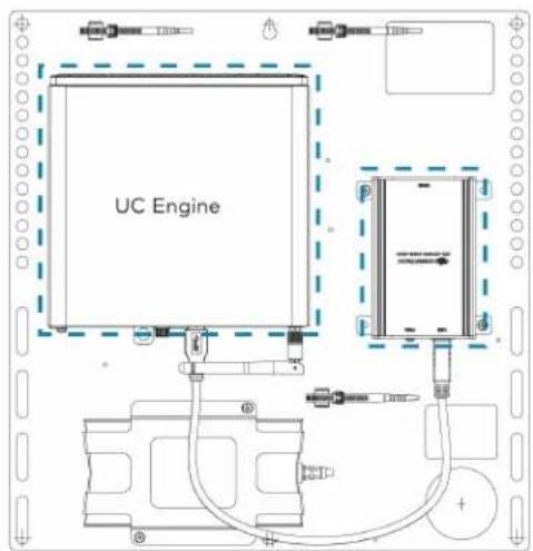
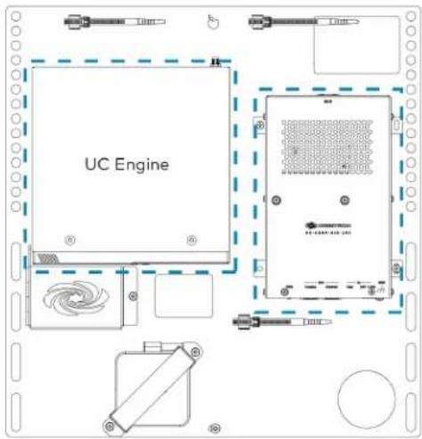
The UC Engine Bracket Assembly streamlines the installation of a Crestron Flex UC system by incorporating the UC Engine and content ingest device on one convenient mounting bracket. A bracket assembly is sold exclusively as part of a Crestron Flex UC video conferencing room solution.

text_image
UC Engine HD-CONV Content Ingest Device- UC Engine: A computer that runs the conferencing software. The computer model varies between systems but is referred to here as the UC Engine.
- Content Ingest Device: An ingest device that connects to the user's computer for sharing content with meeting attendees.
The complete assembly can be mounted on a wall, or it can be attached to the rear of a display device 1-gang sized cutout at the lower right-hand corner allows for mounting over a flush wall-mounted electrical box to manage wiring and conceal connections for a clean, secure installation.
The bracket assemblies are categorized as:
Standard Bracket Assembly
Crestron Flex solutions with a standard bracket assembly deliver a complete video conferencing solution except for the Bring Your Own Device (BYOD) functionality. Bracket assemblies come in various configurations, as shown below, and are shipped based on availability.
NOTE: The shipped bracket assembly may look different from what appears on the Crestron website. However, all bracket assemblies offer the same functionality and performance as committed on the selected Crestron Flex solution's product specifications sheet or web page.
UC Bracket Assembly with Dell UC Engine and HD-UC Bracket Assembly with Dell UC Engine and HD-CONV-CONV-USB-200 USB-300
text_image
UC Engine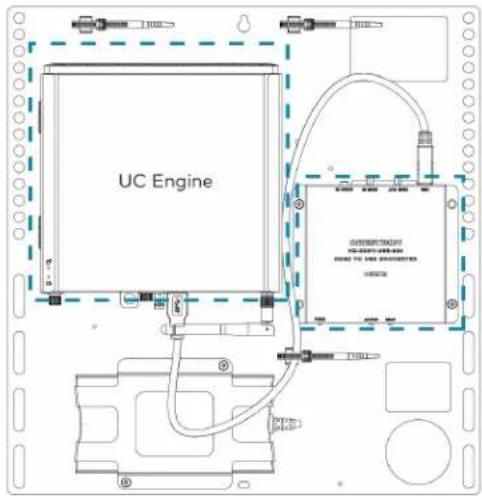
text_image
UC EngineUC Bracket Assembly with ASUS UC Engine and HD-CONV-USB-200
text_image
UC EnginePremium Bracket Assembly
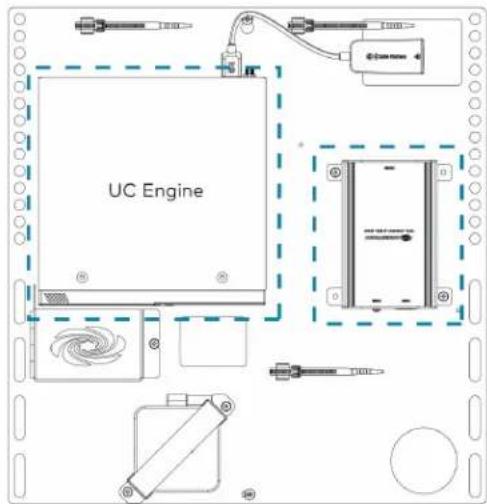
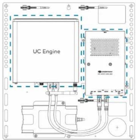
Crestron Flex solutions with a premium bracket assembly deliver a complete video conferencing solution, including the Bring Your Own Device (BYOD) functionality. Bracket assemblies come in various configurations, as shown below, and are shipped based on availability.
NOTE: The shipped bracket assembly may look different from what appears on the Crestron website. However, all bracket assemblies offer the same functionality and performance as committed on the selected Crestron Flex solution's product specifications sheet or web page.
UC Bracket Assembly with Dell UC Engine and HD-UC Bracket Assembly with ASUS UC Engine and HD-CONV-CONV-USB-260 USB-260
text_image
UC Engine
text_image
UC EngineUC Bracket Assembly with ASUS UC Engine and HD-CONV-USB-250
text_image
UC EngineControl Device
A control device operates the conference system controls. Crestron Flex solutions typically use the following control devices:
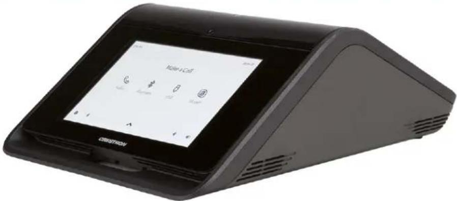
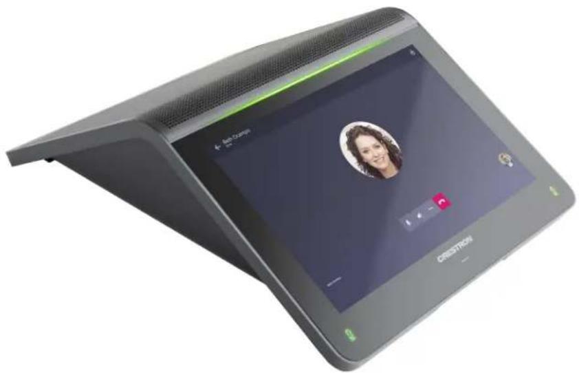
Crestron Mercury and Mercury X Tabletop Conference Device
The Crestron Mercury / Mercury X Tabletop Conference System is a high-performance, full duplex conferencing speakerphone and touch screen controller with extensive connectivity for BYOD scenarios and UC conference systems.
NOTE: The Crestron Mercury conference system receives and plays program audio for Crestron Flex through its built-in microphones and speaker.
text_image
Make a Call CISIKITROVCrestron Mini Tabletop Conference Device
The mini tabletop conference device is a full-featured VoIP conferencing speakerphone that facilitates conversations with exceptional audio fidelity and pickup using the device's integrated 360° quad microphone array. Its high-powered, full-range speaker produces high quality audio for both voice and program material. AEC technology achieves transparent full-duplex performance free of distracting echo or noise, and wideband audio codec support allows for full-spectrum, bidirectional voice communication.
NOTE: The Crestron Mercury conference system receives and plays program audio for Crestron Flex through its built-in microphones and speaker.

natural_image
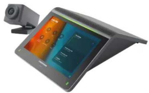
Exterior view of a modern flat-screen digital device with a video call interface (no readable text or symbols on the device body)Tabletop or Wall Mount Touch Screen
With a large 10.1 in. (257 mm) capacitive touch screen display, the Crestron touch screen provides superior conferencing control in meeting rooms, huddle spaces, and executive offices. The touch screen also offers optional control of room lighting, shades, thermostats, and other equipment.
Tabletop Touch Screen Wall Mount Touch Screen
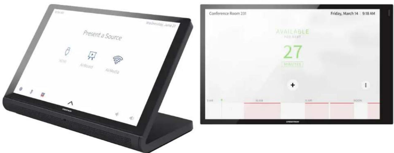
text_image
Present a Source Home Airboard AirMedia Conference Room 231 Friday, March 14 9:18 AM AVAILABLE FOR NEXT 27 MINUTES + T:AM X:AM S:AM ROOMCamera
Crestron Flex solutions offer the following high-definition cameras based on the selected videoconferencing solution.
NOTE: Some Crestron Flex solutions do not include a camera. These solutions require the installer to supply a USB conference camera.
UC-CAM-L1
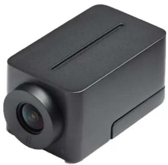
The UC-CAM-L1 is an intelligent, high-definition collaboration camera compatible with Crestron Flex large meeting room videoconferencing solutions. It features a wide-angle 103° diagonal field of view to capture an entire conference room with Full HD 1080p resolution. High precision aspherical optics, a 20.30 MP 1 in. CMOS sensor, portrait lighting, and advanced video processing ensure an immersive, crystal clear video image free from light or noise artifacts or optical aberrations. The camera has no moving parts, ensuring quiet operation, reliability, and accuracy while adjusting Pan, Tilt and Zoom functions.
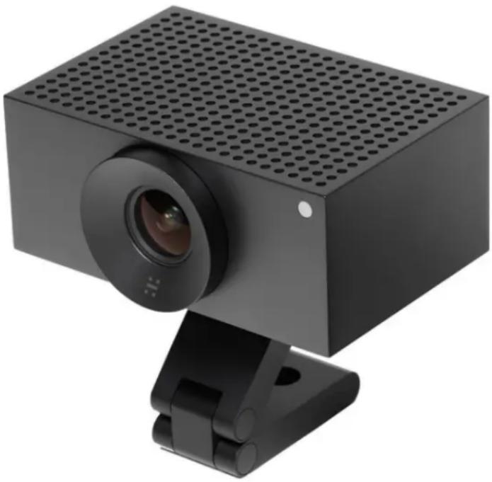
natural_image
Black rectangular device with perforated top and camera lens mounted on a stand (no visible text or symbols)CCS-CAM-USB-F-400
Compact in size, yet tremendous on performance, the CCS-CAM-USB-F-400 camera features an ultra wide-angle 150° diagonal field of view to capture an entire conference room with Full HD 1080p resolution. High precision aspherical optics, a 12 MP CMOS sensor, and advanced video processing ensure an immersive, crystal clear video image free from light or noise artifacts or optical aberrations. The camera has no moving parts, ensuring quiet operation, reliability, and accuracy.
natural_image
Black rectangular electronic device with a lens and ventilation slots (no visible text or symbols)Intelligent Videobar
Crestron Flex solutions offer the following intelligent videobars based on the selected videoconferencing solution.
NOTES:
- Crestron Flex solutions supplied with a Crestron Mercury conference system do not include a Crestron Flex Soundbar. The Crestron Mercury conference system receives and plays program audio through its built-in microphones and speaker.
- Some Crestron Flex solutions do not include a Crestron Mercury conference system or Crestron Flex Soundbar. These solutions require the installer to supply audio equipment to receive and play program audio.
UC-SB2-CAM-A-Z
The powerful and elegant all-in-one (AIO) Crestron Videobar 70 provides a convenient and compact conferencing solution for medium to large-sized meeting rooms. It comprises:
- A quad-camera setup that captures the full room in 4K, automatically tracks and frames the presenter or everyone in the room based on its configuration, and enhances the video content using AI.
- 10-watt dual speakers produce full, rich, and natural-sounding audio. Additional digital signal processing with AEC and noise reduction assures optimal sound quality for an immersive experience.
- Integrated 24-microphone array to capture voices throughout the room using adaptive beamforming technology. AI noise cancellation is also provided to ensure crystal-clear communication with exceptional audio fidelity and pickup.
- Android™ OS running on the QCS8250 chipset that ensures a smooth and reliable conferencing experience every time.

natural_image
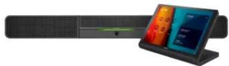
Close-up of a black rectangular object with a green circular highlight on the top (no text or symbols visible)UC-SB1-CAM-FLEX
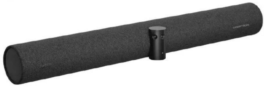
The Crestron UC Video Conference Smart Soundbar & Camera is a front-of-room device that eliminates the need to install additional microphones, speakers, or cameras in a conference space. Mounted on the wall or placed on a credenza beneath the room display(s), the smart soundbar looks great and sounds even better in a small to medium-sized meeting space.

natural_image
Exterior view of a modern office building (no signage)UC-SB-P50(-INDIA)
The Jabra® PanaCast® 50 intelligent videobar for Crestron Flex systems combines microphones, speakers, and cameras in one front-of-room device. High-quality speakers and microphones deliver exceptional full-duplex performance in a small to medium-sized meeting space. Three built-in conferencing cameras capture the room in panoramic 4K resolution with a seamless 180^ horizontal field of view. The Jabra PanaCast 50 is optimized for all leading UC platforms, including both Microsoft Teams Rooms and Zoom Rooms software.
For more information on the Jabra PanaCast 50 video bar for Crestron Flex systems, refer to Jabra PanaCast 50.
natural_image
Black cylindrical object with textured surface and a small protruding knob, labeled 'Jabra' (no other text or symbols visible)UC-PR
The UC Presentation Transmitter provides the BYOD functionality by switching to the connected laptop's UC platform and returning to the native Microsoft Teams Rooms or Zoom Rooms platform when disconnected.

text_image
CREATION HCMN DC PREMENSING TRANSMITTERS HCMN PoE+ PHE 30W MAX CLASS A ACC USB A USB B USB HDMI IN PoE+ PHE 30W MAX CLASS A ACC USB A USB B USB HDMI INHDMI® over CATx Receiver
The HD-RX-USB-2000-C HDMI ^® over CATx receiver brings the BYOD functionality by enabling high-definition video presentations from all types of BYOD sources. The HD-RX-USB-2000-C is a receiver for uncompressed HDMI ^® , CEC, RS-232, Ethernet, and IR signals sent from a CCS-UC-1-X Crestron Mercury ^® X Tabletop Conference System. It is intended for use with the CCS-UC-1-X, the CCS-CAM-USB-F-400 camera, and a single HD or UHD display device (not included).
NOTES:
- The HDMI over CATx Receiver is required only for Crestron Flex kits using a Crestron Mercury X Tabletop Conference device for open-platform UC applications.
- This product is not addressable from a control system and offers no programmable functionality. Video, audio, CEC, IR, Ethernet, and RS-232 signals are simply passed through.

text_image
CHESTRON HLD-RX-USB-2000-0 POWER HDMI OUT 1.5GHz HDMI OUT AUDIO OUT AUTO HOST DEVICE POWER HDMI OUT LINK HDMI OUT AUDIO OUT L + - + + - AUTO HOST DEVICEExtension Microphone Pod
The CCS-UCA-MIC is a low-profile extension microphone pod designed exclusively for use with a Crestron Flex Tabletop Conference System. Up to two mic pods may be connected to a single conference device to extend its pickup range to cover large tables.
Optionally, two microphone pods may be daisy-chained, or connected to the mic pod ports on the rear of the conference device, using the cables provided with each microphone pod.
NOTE: The extension microphone pod can only connect to a Crestron Mercury or Crestron Mercury X tabletop conference device.
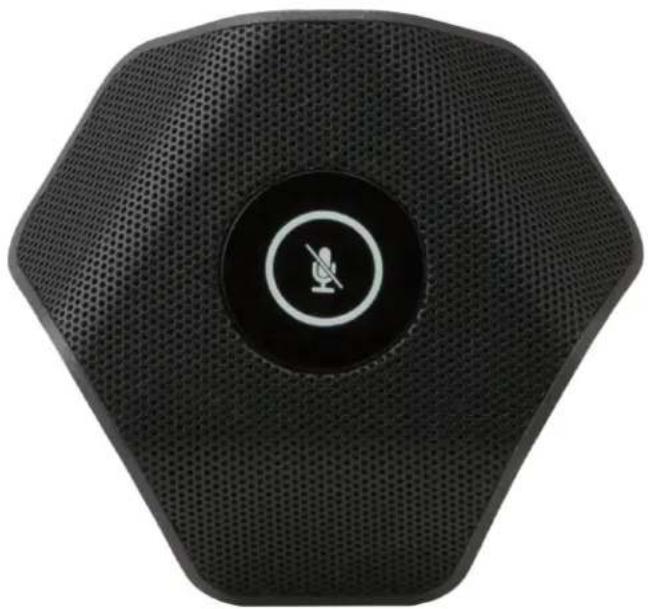
natural_image
Black octagonal electronic device with a circular button and microphone symbol (no text or labels visible)Room Design
The room designs for Crestron Flex are based on the conference room size, conferencing software, and control device.
NOTE: These room designs show a typical hardware arrangement in a small, medium, large, or custom room. Hardware combinations may differ based on the selected Crestron Flex solution.
This section provides the following information:
- Small Room Application
• Medium Room Application
• Large Room Application - Custom Room Application
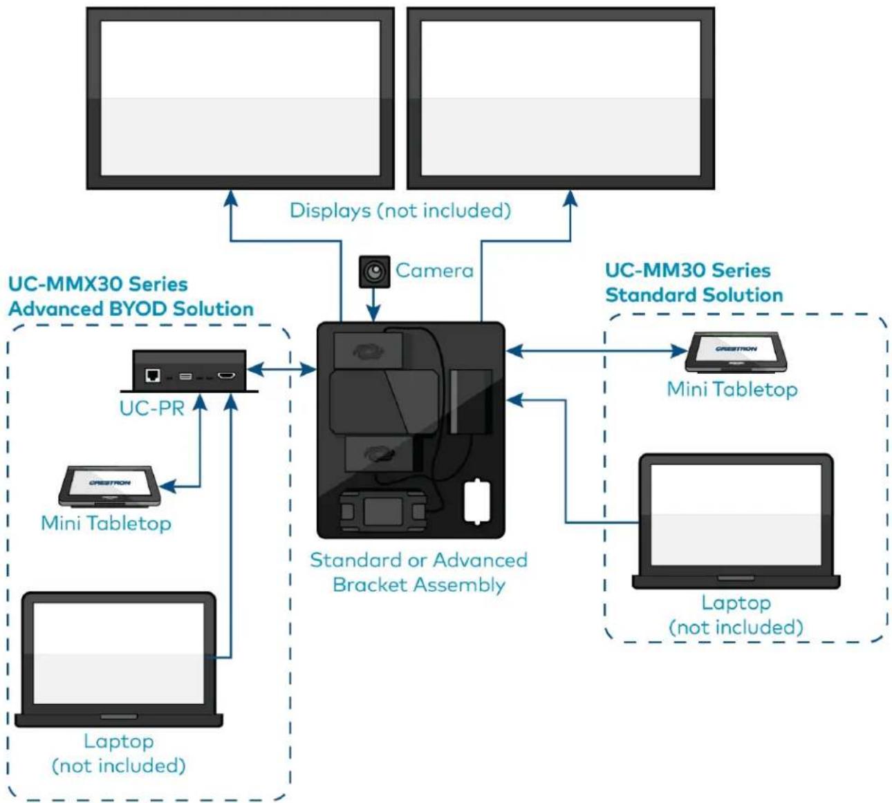
Small Room Application
Scenario 1: Tabletop video conferencing system
• Conferencing software: Microsoft Teams Rooms or Zoom Rooms
• Control device: Mini Tabletop conference device
• Applicable to: MM30 / MMX30 series conferencing solutions
flowchart
graph TD
    A["User"] -->|Displays (not included)| B["Camera"]
    B --> C["UC-MMX30 Series Advanced BYOD Solution"]
    C --> D["UC-PR"]
    D --> E["MC1"]
    F["Laptop (not included)"] --> G["Mini Tabletop"]
    H["Laptop (not included)"] --> I["MC1"]
    J["User"] --> K["UC-MMX30 Series Standard Solution"]
    K --> L["CREESTRON"]
    K --> M["Mini Tabletop"]
    K --> N["Laptop (not included)"]
    O["User"] --> P["Standard or Advanced Bracket Assembly"]
    P --> Q["Camera"]
    Q --> R["UC-MMX30 Series Advanced BYOD Solution"]
    R --> S["UC-PR"]
    S --> T["MC1"]
    U["User"] --> V["Standard or Advanced Bracket Assembly"]
    V --> W["Laptop (not included)"]
    X["User"] --> Y["UC-MMX30 Series Standard Solution"]
    Y --> Z["CREESTRON"]
    Y --> AA["Mini Tabletop"]
    Y --> AB["Laptop (not included)"]
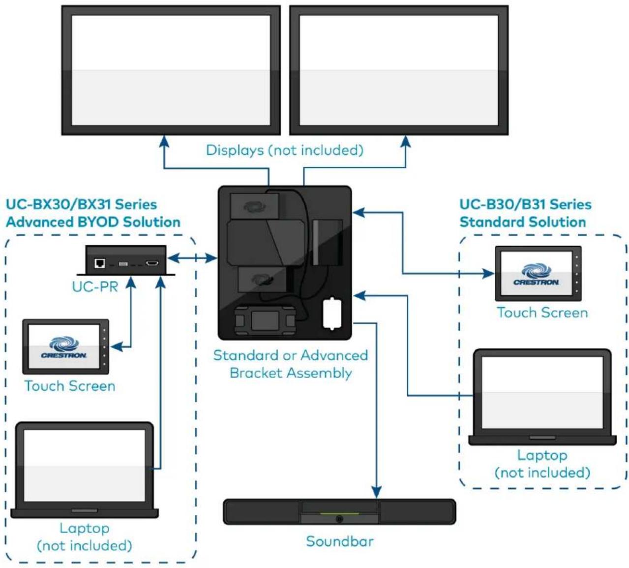
Scenario 2: Front-of-room video conferencing system
• Conferencing software: Microsoft Teams Rooms or Zoom Rooms
• Control device: Wall mount or surface mount touch screen
• Applicable to: B30 / BX30 and B31 / BX31 series conferencing solutions
flowchart
graph TD
    A["User"] -->|Displays (not included)| B["Standard or Advanced Bracket Assembly"]
    C["User"] -->|Displays (not included)| B
    D["User"] -->|Displays (not included)| B
    E["User"] -->|Displays (not included)| F["UC-BX30/BX31 Series Advanced BYOD Solution"]
    G["User"] -->|Displays (not included)| H["UC-BX30/BX31 Series Standard Solution"]
    I["User"] -->|Displays (not included)| J["UC-B30/B31 Series Standard Solution"]
    K["User"] -->|Displays (not included)| L["UC-B30/B31 Series Advanced BYOD Solution"]
    M["User"] -->|Displays (not included)| N["Laptop (not included)"]
    O["User"] -->|Displays (not included)| P["UC-B30/B31 Series Standard Solution"]
    Q["User"] -->|Displays (not included)| R["UC-B30/B31 Series Advanced BYOD Solution"]
    S["User"] -->|Displays (not included)| T["UC-B30/B31 Series Standard Solution"]
    U["User"] -->|Displays (not included)| V["UC-B30/B31 Series Advanced BYOD Solution"]
    W["User"] -->|Displays (not included)| X["Laptop (not included)"]
    Y["User"] -->|Displays (not included)| Z["UC-B30/B31 Series Standard Solution"]
    AA["User"] -->|Displays (not included)| AB["UC-B30/B31 Series Advanced BYOD Solution"]
    AC["User"] -->|Displays (not included)| AD["UC-B30/B31 Series Standard Solution"]
    AE["User"] -->|Displays (not included)| AF["UC-B30/B31 Series Advanced BYOD Solution"]
    AG["User"] -->|Displays (not included)| AH["UC-B30/B31 Series Standard Solution"]
    AI["User"] -->|Displays (not included)| AJ["UC-B30/B31 Series Advanced BYOD Solution"]
    AK["User"] -->|Displays (not included)| AL["UC-B30/B31 Series Standard Solution"]
    AM["User"] -->|Displays (not included)| AN["UC-B30/B31 Series Advanced BYOD Solution"]
    AO["User"] -->|Displays (not included)| AP["UC-B30/B31 Series Standard Solution"]
    AQ["User"] -->|Displays (not included)| AR["UC-B30/B31 Series Advanced BYOD Solution"]
    AS["User"] -->|Displays (not included)| AT["UC-B30/B31 Series Standard Solution"]
    AU["User"] -->|Displays (not included)| AV["UC-B30/B31 Series Advanced BYOD Solution"]
    AW["User"] -->|Displays (not included)| AX["UC-B30/B31 Series Standard Solution"]
    AY["User"] -->|Displays (not included)| AZ["UC-B30/B31 Series Advanced BYOD Solution"]
    BA["User"] -->|Displays (not included)| BB["UC-B30/B31 Series Standard Solution"]
    BC["User"] -->|Displays (not included)| BD["UC-B30/B31 Series Advanced BYOD Solution"]
    BE["User"] -->|Displays (not included)| BF["UC-B30/B31 Series Standard Solution"]
    BG["User"] -->|Displays (not included)| BH["UC-B30/B31 Series Advanced BYOD Solution"]
    BI["User"] -->|Displays (not included)| BJ["UC-B30/B31 Series Standard Solution"]
    BK["User"] -->|Displays (not included)| BL["UC-B30/B31 Series Advanced BYOD Solution"]
    BM["User"] -->|Displays (not included)| BN["UC-B30/B31 Series Standard Solution"]
    BO["User"] -->|Displays (not included)| BP["UC-B30/B31 Series Advanced BYOD Solution"]
    BQ["User"] -->|Displays (not included)| BQ["UC-B30/B31 Series Standard Solution"]
    BR["User"] -->|Displays (not included)| BS["UC-B30/B31 Series Advanced BYOD Solution"]
    BT["User"] -->|Displays (not included)| BU["UC-B30/B31 Series Standard Solution"]
    BV["User"] -->|Displays (not included)| BW["UC-B30/B31 Series Advanced BYOD Solution"]
    BX["User"] -->|Displays (not included)| BY["UC-B30/B31 Series Standard Solution"]
    BZ["User"] -->|Displays (not included)| BZ["UC-B30/B31 Series Advanced BYOD Solution"]
    CA["User"] -->|Displays (not included)| CB["UC-B30/B31 Series Standard Solution"]
    CC["User"] -->|Displays (not included)| CD["UC-B30/B31 Series Advanced BYOD Solution"]
    CE["User"] -->|Displays (not included)| CF["UC-B30/B31 Series Standard Solution"]
    CG["User"] -->|Displays (not included)| DH["UC-B30/B31 Series Advanced BYOD Solution"]
    DI["User"] -->|Displays (not included)| DJ["UC-B30/B31 Series Standard Solution"]
    DK["User"] -->|Displays (not included)| DL["UC-B30/B31 Series Advanced BYOD Solution"]
    DV["User"] -->|Displays (not included)| DV["UC-B30/B31 Series Standard Solution"]
    DW["User"] -->|Displays (not included)| DWA["UC-B30/B31 Series Advanced BYOD Solution"]
    DX["User"] -->|Displays (not included)| DXB["UC-B30/B31 Series Standard Solution"]
    DXC["User"] -->|Displays (not included)| DXD["UC-B30/B31 Series Advanced BYOD Solution"]
    DXE["User"] -->|Displays (not included)| DXEAB["UC-B30/B31 Series Standard Solution"]
    DXF["User"] -->|Displays (not included)| DXFAB["UC-B30/B31 Series Advanced BYOD Solution"]
    DXG["User"] -->|Displays (not included)| DXGAB["UC-B30/B31 Series Standard Solution"]
    DXH["User"] -->|Displays (not included)| DXHAB["UC-B30/B31 Series Advanced BYOD Solution"]
    DXI["User"] -->|Displays (not included)| DXIAB["UC-B30/B31 Series Standard Solution"]
    DXJ["User"] -->|Displays (not included)| DXJAB["UC-B30/B31 Series Advanced BYOD Solution"]
    DXK["User"] -->|Displays (not included)| DXKAB["UC-B30/B31 Series Standard Solution"]
    DXL["User"] -->|Displays (not included)| DXLAB["UC-B30/B31 Series Advanced BYOD Solution"]
    DXM["User"] -->|Displays (not included)| DXMAB["UC-B30/B31 Series Standard Solution"]
    DXN["User"] -->|Displays (not included)| DXNAB["UC-B30/B31 Series Advanced BYOD Solution"]
    DXO["User"] -->|Displays (not included)| DXOAB["UC-B30/B31 Series Standard Solution"]
Medium Room Application
Scenario 1: Tabletop video conferencing system
• Conferencing software: Microsoft Teams Rooms or Zoom Rooms
• Control device: Crestron Mercury or Crestron Mercury X
• Applicable to: M50 / MX50 series conferencing solutions

flowchart
graph TD
    A["Computer"] -->|Displays (not included)| B["Camera"]
    C["Computer"] -->|Displays (not included)| B
    D["Computer"] -->|Displays (not included)| B
    E["Computer"] -->|Displays (not included)| F["Standard or Advanced Bracket Assembly"]
    G["Computer"] -->|Displays (not included)| F
    H["Computer"] -->|Displays (not included)| I["Crestron Mercury X"]
    J["Computer"] -->|Displays (not included)| K["Laptop (not included)"]
    L["Computer"] -->|Displays (not included)| M["UC-MX50 Series Advanced BYOD Solution"]
    N["Computer"] -->|Displays (not included)| O["UC-M50 Series Standard Solution"]
    P["Computer"] -->|Displays (not included)| Q["Crestron Mercury"]
    R["Computer"] -->|Displays (not included)| S["Laptop (not included)"]
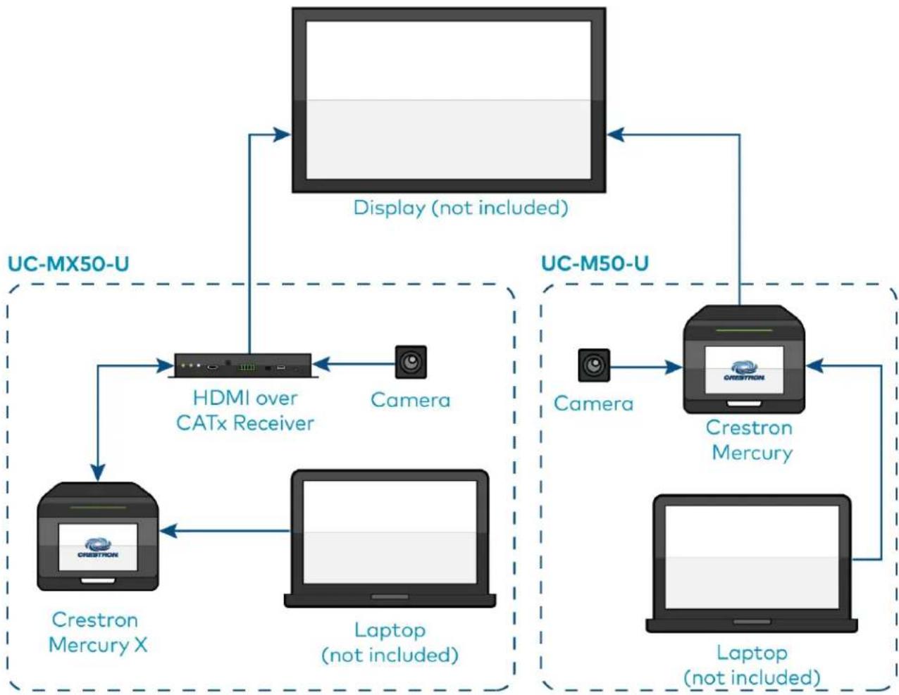
Scenario 2: Tabletop video conferencing system
• Conferencing software: Open-platform UC applications
• Control device: Crestron Mercury or Crestron Mercury X
• Applicable to: M50 / MX50 series conferencing solutions
flowchart
graph TD
    A["Crestron Mercury X"] --> B["HDMI over CATx Receiver"]
    B --> C["Laptop (not included)"]
    C --> D["Camera"]
    D --> E["Display (not included)"]
    E --> F["UC-MX50-U"]
    G["Crestron Mercury"] --> H["Camera"]
    H --> I["Display (not included)"]
    I --> J["UC-M50-U"]
    K["Laptop (not included)"] --> L["Display (not included)"]
    L --> M["Camera"]
    M --> N["Display (not included)"]
    N --> O["UC-M50-U"]
Scenario 3: Front-of-room video conferencing system
• Conferencing software: Zoom Rooms
• Control device: Wall mount or surface mount touch screen
• Applicable to: B70 series conferencing solutions

flowchart
graph TD
    A["Touch Screen"] --> B["UC-SB2-CAM-A Series Videobar"]
    C["Laptop (not included)"] --> B
    D["Display (not included)"] --> B
    B --> E["User Interface Box"]
    style B fill:#000,stroke:#000,color:#fff
    style A fill:#000,stroke:#000,color:#fff
    style C fill:#000,stroke:#000,color:#fff
    style D fill:#000,stroke:#000,color:#fff
Large Room Application
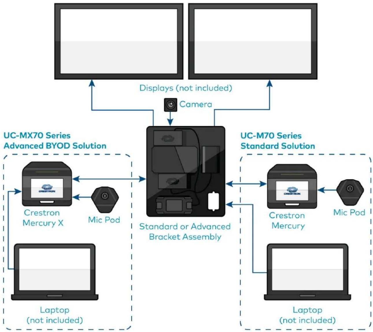
Scenario 1: Tabletop video conferencing system
• Conferencing software: Microsoft Teams Rooms or Zoom Rooms
• Control device: Crestron Mercury or Crestron Mercury X
• Applicable to: M70 / MX70 series conferencing solutions
flowchart
graph TD
    A["User"] --> B["UC-MX70 Series Advanced BYOD Solution"]
    B --> C["Crestron Mercury X"]
    B --> D["Mic Pod"]
    C <--> E["Standard or Advanced Bracket Assembly"]
    D <--> E
    F["Laptop (not included)"] --> B
    G["Laptop (not included)"] --> C
    H["Camera"] --> E
    I["Displays (not included)"] --> B
    J["UC-M70 Series Standard Solution"] --> K["Crestron Mercury"]
    J --> L["Mic Pod"]
    K <--> M["Standard or Advanced Bracket Assembly"]
    L <--> M
    M <--> N["UC-M70 Series Advanced BYOD Solution"]
    N --> O["Crestron Mercury X"]
    N --> P["Mic Pod"]
Scenario 2: Tabletop video conferencing system
- Conferencing software: Open-platform UC applications
• Control device: Crestron Mercury or Crestron Mercury X
• Applicable to: M70 / MX70 series conferencing solutions

flowchart
graph TD
    subgraph_UC-MX70-U["UC-MX70-U"]
        A["Mic Pod"] --> B["Crestron Mercury X"]
        B --> C["HDMI over CATx Receiver"]
        C --> D["Laptop (not included)"]
        D --> E["Camera"]
        E --> F["Display (not included)"]
    end

    subgraph_UC-M70-U["UC-M70-U"]
        G["Camera"] --> H["Crestron Mercury"]
        H --> I["Laptop (not included)"]
        I --> J["Mic Pod"]
        J --> K["Display (not included)"]
    end

    style UC-MX70-U fill:#f9f,stroke:#333
    style UC-M70-U fill:#ccf,stroke:#333
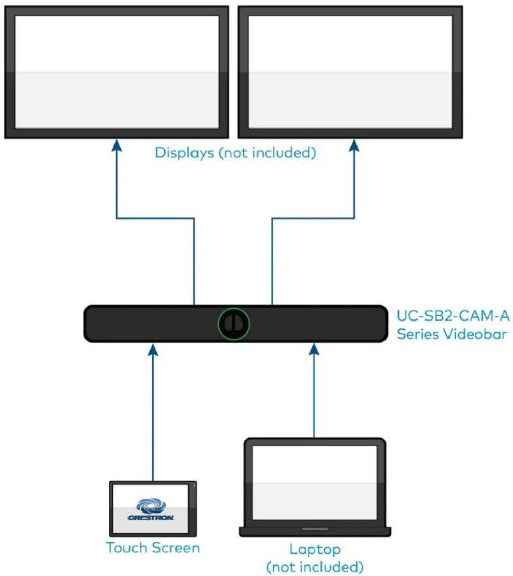
Scenario 3: Front-of-room video conferencing system
• Conferencing software: Zoom Rooms
• Control device: Wall mount or surface mount touch screen
• Applicable to: B70 series conferencing solutions
flowchart
graph TD
    A["Touch Screen"] --> B["UC-SB2-CAM-A Series Videobar"]
    C["Laptop (not included)"] --> B
    D["Display (not included)"] --> B
    B --> E["User Interface Box"]
    style B fill:#000,stroke:#000,color:#fff
    style A fill:#000,stroke:#000,color:#fff
    style C fill:#000,stroke:#000,color:#fff
    style D fill:#000,stroke:#000,color:#fff
Custom Room Application
- Conference room size: Custom (audio and video devices need to be purchased separately)
• Conferencing software: Microsoft Teams Rooms or Zoom Rooms
• Control device: Wall mount or surface mount touch screen
• Applicable to: C100 / CX100 series conferencing solutions
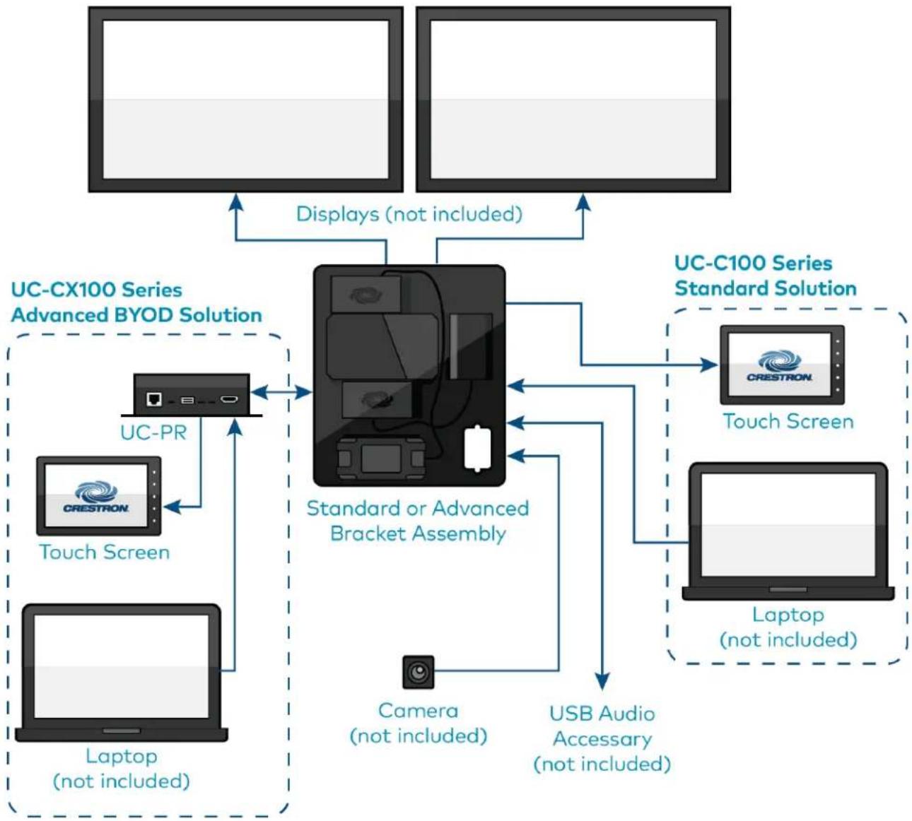
flowchart
graph TD
    A["User"] -->|Displays (not included)| B["Standard or Advanced Bracket Assembly"]
    C["User"] -->|Displays (not included)| B
    D["User"] -->|Displays (not included)| B
    E["User"] -->|Displays (not included)| F["UC-CX100 Series Advanced BYOD Solution"]
    G["User"] -->|Displays (not included)| H["UC-C100 Series Standard Solution"]
    I["User"] -->|Displays (not included)| J["UC-CX100 Series Standard Solution"]
    K["User"] -->|Displays (not included)| L["UC-CX100 Series Standard Solution"]
    M["User"] -->|Displays (not included)| N["UC-CX100 Series Standard Solution"]
    O["User"] -->|Displays (not included)| P["UC-CX100 Series Standard Solution"]
    Q["User"] -->|Displays (not included)| R["UC-CX100 Series Standard Solution"]
    S["User"] -->|Displays (not included)| T["UC-CX100 Series Standard Solution"]
    U["User"] -->|Displays (not included)| V["UC-CX100 Series Standard Solution"]
    W["User"] -->|Displays (not included)| X["UC-CX100 Series Standard Solution"]
    Y["User"] -->|Displays (not included)| Z["UC-CX100 Series Standard Solution"]
    AA["User"] -->|Displays (not included)| AB["UC-CX100 Series Standard Solution"]
    AC["User"] -->|Displays (not included)| AD["UC-CX100 Series Standard Solution"]
    AE["User"] -->|Displays (not included)| AF["UC-CX100 Series Standard Solution"]
    AG["User"] -->|Displays (not included)| AH["UC-CX100 Series Standard Solution"]
    AI["User"] -->|Displays (not included)| AJ["UC-CX100 Series Standard Solution"]
    AK["User"] -->|Displays (not included)| AL["UC-CX100 Series Standard Solution"]
    AM["User"] -->|Displays (not included)| AN["UC-CX100 Series Standard Solution"]
    AO["User"] -->|Displays (not included)| AP["UC-CX100 Series Standard Solution"]
    AQ["User"] -->|Displays (not included)| AR["UC-CX100 Series Standard Solution"]
    AS["User"] -->|Displays (not included)| AT["UC-CX100 Series Standard Solution"]
    AU["User"] -->|Displays (not included)| AV["UC-CX100 Series Standard Solution"]
    AW["User"] -->|Displays (not included)| AX["UC-CX100 Series Standard Solution"]
    AY["User"] -->|Displays (not included)| AZ["UC-CX100 Series Standard Solution"]
    BA["User"] -->|Displays (not included)| BB["UC-CX100 Series Standard Solution"]
    BC["User"] -->|Displays (not included)| BD["UC-CX100 Series Standard Solution"]
    BE["User"] -->|Displays (not included)| BF["UC-CX100 Series Standard Solution"]
    BG["User"] -->|Displays (not included)| BH["UC-CX100 Series Standard Solution"]
    BI["User"] -->|Displays (not included)| BJ["UC-CX100 Series Standard Solution"]
    BK["User"] -->|Displays (not included)| BL["UC-CX100 Series Standard Solution"]
    BM["User"] -->|Displays (not included)| BN["UC-CX100 Series Standard Solution"]
    BO["Laptop (not included)"] --> BP["Laptop (not included)"]
    BP["Laptop (not included)"] --> BQ["Laptop (not included)"]
    BR["Laptop (not included)"] --> BS["Laptop (not included)"]
    BT["Laptop (not included)"] --> BU["Laptop (not included)"]
    BV["Laptop (not included)"] --> BW["Laptop (not included)"]
    BX["Laptop (not included)"] --> BY["Laptop (not included)"]
    BZ["Laptop (not included)"] --> CA["Laptop (not included)"]
    CB["Laptop (not included)"] --> CC["Laptop (not included)"]
    DD["Laptop (not included)"] --> DE["Laptop (not included)"]
    DF["Laptop (not included)"] --> DG["Laptop (not included)"]
    DH["Laptop (not included)"] --> DI["Laptop (not included)"]
    DJ["Laptop (not included)"] --> DK["Laptop (not included)"]
    DL["Laptop (not included)"] --> DV["Laptop (not included)"]
    DW["Laptop (not included)"] --> DX["Laptop (not included)"]
    DX["Laptop (not included)"]
Microsoft Teams® Rooms Solution
Crestron Flex makes any space a productive Microsoft Teams Room. From hotdesking to training rooms, Crestron Flex products deliver the optimum audio and video to each space. With the ease of one touch join and the ability to effortlessly move a meeting from the desktop to the conference room, Crestron Flex enables teams to work together more efficiently. For more details regarding Crestron Flex and Microsoft Teams collaboration, refer to Crestron Flex + Microsoft Teams.
Select the following sections to learn about the product features, specifications, installation, configuration, and operation for all UC B30/BX30, C100/CX100, MM30/MMX30, M50/MX50, and M70/MX70 series Microsoft Teams Rooms solutions.
Features
Refer to the following sections for more information on the features provided by various Microsoft Teams Rooms solutions.
UC-B30-T and UC-B31-T Series Features
The UC-B30-T and UC-B31-T series standard Crestron Flex tabletop front-of-room video conferencing system provides a small room video conference solution for use with Microsoft Teams® Rooms software. It supports single or dual video display (not included).
UC-B30-T UC-B30-T-WM
natural_image
Exterior view of a modern office building (no signage)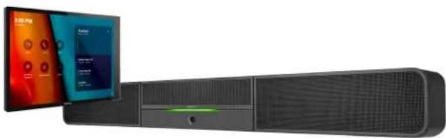
natural_image
Exterior view of a modern office building (no signage)UC-B31-T / UC-B31-T-INDIA

natural_image
Black cylindrical electronic device with a small screen showing colorful interface elements (no visible text or symbols)natural_image
Black cylindrical electronic device with a sensor and control panel inset showing a 3:00 PM display (no visible text or symbols on device body)Included Components
| UC-B30-T | UC-B31-T(-INDIA) | UC-B30-T-WM | UC-B31-T-WM(-INDIA) | |
| UC-SB1-CAM-FLEX | √ | ✗ | √ | ✗ |
| UC-SB-P50 or UC-SB-P50-INDIA | ✗ | √ | ✗ | √ |
| TS-1070-B-S-T-V | √ | √ | ✗ | ✗ |
| TSW-1070-B-S-T-V | ✗ | ✗ | √ | √ |
| UC-BRKT-200-S-T-ASSY | √ | √ | √ | √ |
| PoE Injector | √ | √ | √ | √ |
| Cables | √ | √ | √ | √ |
To view the specifications and dimensions of the included components of the selected kit, refer to Specifications and Dimension Drawings.
Key Features
- Front-of-room video conferencing solution for a Microsoft Teams Rooms environment
- Native Microsoft Teams Rooms touch screen UI provides a consistent user experience with simple operation and one-touch meeting joins
- Optional integration with Crestron control systems
- Direct connection option between UC Engine and touch screen for simple installation and configuration
- Network management and provisioning, system alerts, and the pairing of the touch screen to the system's UC Engine through the XiO Cloud service
• Supports single or dual video displays (not included) - Easy to specify and install — no custom design, programming, or software installation required
- Enterprise-grade security — connects and communicates securely over any enterprise or SMB network
- Premium-level support with Crestron Flex Care (optional)
Native Microsoft Teams Rooms Experience
The conferencing solution brings the full Microsoft Teams Rooms UC experience to any meeting space in an enterprise or SMB facility.
Intuitive User Interface
With a large 10.1 in. (257 mm) capacitive touch screen display, the Crestron tabletop or wall mount touch scree provides superior conferencing control in meeting rooms, huddle spaces, and executive offices. The touch screen also offers optional control of room lighting, shades, thermostats, and other equipment. ^2
Using the bracket provided with the wall mount touch screen, the touch screen is easily installed over a 2-gang or 3-gang US electrical box, or a 2-gang European or UK electrical box. A security latch option is included to deter unauthorized removal of the touch screen.
Simplified Deployment
The UC Bracket Assembly provides preassembled components on one ready-to-mount bracket to simplify installation. The assembly can be mounted on a wall, or it can be attached to the rear of the display device. Crestron's direct connection method further simplifies installation with a single connection from the touch screen to the UC Bracket Assembly.
High-Definition Video Conferencing with Impressive Audio
UC-SB1-CAM-FLEX: High-quality speakers, microphone, and digital signal processing deliver exceptional full-duplex speakerphone performance from the Crestron UC video conference soundbar and camera (UC-SB1-CAM-FLEX). The built-in conferencing camera captures the room in HD 1080p video resolution and with an ultra-wide 150° diagonal field of view.
UC-SB-P50 or UC-SB-P50-INDIA: High-quality speakers and microphones deliver exceptional full-duplex performance from the Jabra PanaCast 50 video bar for Crestron Flex systems (UC-SB-P50 or UC-SB-P50-INDIA). Three built-in conferencing cameras capture the room in panoramic 4K resolution with a seamless 180° horizontal field of view.
Visit jabra.com/panacast50 for more information on the Jabra PanaCast 50 video bar for Crestron Flex systems.
Crestron Control System Integration
The conferencing solution can integrate with a Crestron control system to enable touch screen control of room lighting, motorized window shades, climate control, AV, and other amenities.
Enterprise-Grade Security
Crestron Flex is an enterprise-grade solution, engineered in partnership with Microsoft to integrate seamlessly into any Microsoft Teams Rooms software deployment. Crestron Flex is ideally equipped for mass deployment throughout any sized corporate, university, medical, military, or government facility.
Easy Provisioning and Device Management
The XiO Cloud service is an IoT cloud based provisioning service (available separately) that enables installers and IT managers to deploy and manage thousands of devices easily. The XiO Cloud service allows for system alerts, network management and provisioning, and the pairing of a control device to the system's UC Engine. System updates are controlled by Windows software update.
Visit www.crestron.com/xiocloud for additional information.
Premium-Level Support
Crestron Flex Care is an optional subscription service that automatically renews annually, providing 24/7 live remote technical support, an extended five year warranty on Crestron hardware, expedited advance replacements, and a discounted rate for on-site support.
Visit www.crestron.com/flexcare for detailed terms and conditions and additional information.
Dual Control Option
A TS- or TSW- 70 series 10.1 in. touch screen may be added to the solution as an additional control po for the Microsoft Teams Rooms environment ^23 .
Deployment Resources
View the Pre-Deployment Checklist on page 223 to help plan your Crestron Flex installation.
Notes:
- Display must support "Wake on Sync" and "Sleep on No Sync" functionality. Consult the display manufacturer's specifications or internal settings of the specific display.
- Room control capability (lighting, shades, thermostats, etc.) requires additional equipment and commissioning to be provided by a Crestron authorized integrator and/or programmer. Additional costs may apply.
- Only one control device may be connected via direct connection method.
UC-BX30-T and UC-BX31-T Series Features
The UC-BX30-T and UC-BX31-T series advanced (with BYOD functionality) Crestron Flex tabletop front-of-room video conferencing system provides a small room video conference solution for use with Microsoft Teams® Rooms software. It supports single or dual video displays included).
UC-BX30-T UC-BX30-T-WM

natural_image
Product display setup featuring a network interface, a server unit, and a tablet with colorful screens (no visible text or symbols)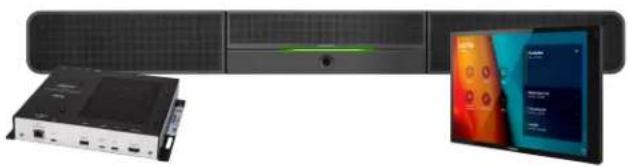
natural_image
Product display setup showing a server rack, a USB drive unit, and a tablet with colorful interface elements (no visible text or symbols)UC-BX31-T / UC-BX31-T-INDIA UC-BX31-T-WM / UC-BX31-T-WM-INDIA

natural_image
Product photo of a black televisions with connected devices and a display screen (no visible text or symbols)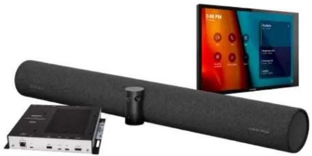
natural_image
Product photo of a black cylindrical audio player with connected audio equipment and a digital screen displaying app icons (no visible text or symbols)Included Components
| UC-BX30-T | UC-BX31-T (-INDIA) | UC-BX30-T-WM | UC-BX31-T-WM(-INDIA) | |
| UC-SB1-CAM-FLEX | √ | ✗ | √ | ✗ |
| UC-SB-P50 or UC-SB-P50-INDIA | ✗ | √ | ✗ | √ |
| TS-1070-B-S-T-V | √ | √ | ✗ | ✗ |
| TSW-1070-B-S-T-V | ✗ | ✗ | √ | √ |
| UC-BRKT-250-P-T-ASSY or UC-BRKT-260-P-T-ASSY | √ | √ | √ | √ |
| UC-PR with Cable Organizer | √ | √ | √ | √ |
| Cables | √ | √ | √ | √ |
To view the specifications and dimensions of the included components of the selected kit, refer to Specifications and Dimension Drawings.
Key Features
- Front-of-room video conferencing solution for a Microsoft Teams Rooms environment
- Native Microsoft Teams Rooms touch screen UI provides a consistent user experience with simple operation and one-touch meeting joins
- Optional integration with Crestron control systems
- Direct connection option between UC Engine and touch screen for simple installation and configuration
- Network management and provisioning, system alerts, and the pairing of the touch screen to the system's UC Engine through the XiO Cloud service
• Supports single or dual video displays (not included) - Present, call, conference, and collaborate using your own device's UC conference platform (BYOD) or the native Microsoft Teams Rooms platform
- Easy to specify and install — no custom design, programming, or software installation required
- Enterprise-grade security — connects and communicates securely over any enterprise or SMB network
- Premium-level support with Crestron Flex Care (optional)
Native Microsoft Teams Rooms Experience
The conferencing solution brings the full Microsoft Teams Rooms UC experience to any meeting space in an enterprise or SMB facility.
Intuitive User Interface
With a large 10.1 in. (257 mm) capacitive touch screen display, the Crestron tabletop or wall mount touch scree provides superior conferencing control in meeting rooms, huddle spaces, and executive offices. The touch screen also offers optional control of room lighting, shades, thermostats, and other equipment. ^2
Using the bracket provided with the wall mount touch screen, the touch screen is easily installed over a 2-gang or 3-gang US electrical box, or a 2-gang European or UK electrical box. A security latch option is included to deter unauthorized removal of the touch screen.
Simplified Deployment
The UC Bracket Assembly provides preassembled components on one ready-to-mount bracket to simplify installation. The assembly can be mounted on a wall, or it can be attached to the rear of the display device. Crestron's direct connection method further simplifies installation with a single connection from the touch screen to the UC Bracket Assembly.
High-Definition Video Conferencing with Impressive Audio
UC-SB1-CAM-FLEX: High-quality speakers, microphone, and digital signal processing deliver exceptional full-duplex speakerphone performance from the Crestron UC video conference soundbar and camera (UC-SB1-CAM-FLEX). The built-in conferencing camera captures the room in HD 1080p video resolution and with an ultra-wide 150° diagonal field of view.
UC-SB-P50 or UC-SB-P50-INDIA: High-quality speakers and microphones deliver exceptional full-duplex performance from the Jabra PanaCast 50 video bar for Crestron Flex systems (UC-SB-P50 or UC-SB-P50-INDIA). Three built-in conferencing cameras capture the room in panoramic 4K resolution with a seamless 180° horizontal field of view.
Visit jabra.com/panacast50 for more information on the Jabra PanaCast 50 video bar for Crestron Flex systems.
Crestron Control System Integration
The conferencing solution can integrate with a Crestron control system to enable touch screen control of room lighting, motorized window shades, climate control, AV, and other amenities.
Bring Your Own Device
Conference room visitors can connect their laptop to the Crestron Flex system to use their own UC conference platform. The UC Presentation Transmitter (UC-PR) switches to the connected laptop's UC platform and returns to the native platform when disconnected. a list of BYOD tested devices on the UC-PR, refer to OLH Article 1000889.
Enterprise-Grade Security
Crestron Flex is an enterprise-grade solution, engineered in partnership with Microsoft to integrate seamlessly into any Microsoft Teams Rooms software deployment. Crestron Flex is ideally equipped for mass deployment throughout any sized corporate, university, medical, military, or government facility.
Easy Provisioning and Device Management
The XiO Cloud service is an IoT cloud based provisioning service (available separately) that enables installers and IT managers to deploy and manage thousands of devices easily. The XiO Cloud service allows for system alerts, network management and provisioning, and the pairing of a control device to the system's UC Engine. System updates are controlled by Windows software update.
Visit www.crestron.com/xiocloud for additional information.
Premium-Level Support
Crestron Flex Care is an optional subscription service that automatically renews annually, providing 24/7 live remote technical support, an extended five year warranty on Crestron hardware, expedited advance replacements, and a discounted rate for on-site support.
Visit www.crestron.com/flexcare for detailed terms and conditions and additional information.
Dual Control Option
A TS- or TSW- 70 series 10.1 in. touch screen may be added to the solution as an additional control po for the Microsoft Teams Rooms environment ^2,3 .
Deployment Resources
View the Pre-Deployment Checklist on page 223 to help plan your Crestron Flex installation.
Notes:
- Display must support "Wake on Sync" and "Sleep on No Sync" functionality. Consult the display manufacturer's specifications or internal settings of the specific display.
- Room control capability (lighting, shades, thermostats, etc.) requires additional equipment and commissioning to be provided by a Crestron authorized integrator and/or programmer. Additional costs may apply.
- Only one control device may be connected via direct connection method.
- The UC-PR uses a USB-C 2.0 connection to provide content sharing, BYOD support, and charging for a user's device. Because USB-C supports multiple functions, device compatibility often varies. While some devices can accept power and data through the same USB-C connection, others cannot. The USB-C port on the UC-PR (labelled "USB") uses DisplayPort alternate mode for transporting video signals. Consult the connected device's user manual or manufacturer to ensure that the device supports DisplayPort alternate mode. Some devices that support DisplayPort alternate mode may not support device charging. For a list of tested devices, refer to OLH Article 1000889. USB-C transfer speeds may vary based on the connected device's processing speed, system configuration, the operating environment, and/or other factors. If the user's device does not support USB-C, then a combination of HDMI and USB B may be used for content sharing or BYOD functionality. For details, see Connections (UC-BX30-T and UC-BX31-T series).
UC-MM30-TA and UC-MM30-TA-I Features
The Crestron Flex UC-MM30-TA and UC-MM30-TA-I system provides an audio conference room solution for use with the Microsoft Teams Rooms intelligent communications platform. It features a Crestron Flex tabletop conference device (UC-2).
natural_image
Exterior view of a modern office building (no signage)Included Components
| UC-MM30-TA UC-MM30-TA-I | ||
| UC-2 Mini Tabletop Conference Device | √ | √ |
To view the specifications and dimensions of the included components of the selected kit, refer to Specifications and Dimension Drawings.
Key Features
- Tabletop conferencing solution for Microsoft Teams Rooms environment
- Native Microsoft Teams Rooms touch screen UI provides a consistent user experience with simple operation and one-touch meeting joins
• Network management and provisioning and system alerts through the XiO Cloud service - Dual-band Wi-Fi® connection
- Easy to specify and install — no custom design, programming, or software installation required
- Enterprise-grade security — connects and communicates securely over any enterprise or SMB network
- Premium-level support with Crestron Flex Care (optional)
Native Microsoft Teams Rooms Experience
The conferencing solution brings the full Microsoft Teams Rooms UC experience to any meeting space in an enterprise or SMB facility.
Intuitive User Interface with Impressive Audio
With a large 7 in. HD color touch screen and an integrated AEC-enabled USB speakerphone that affords full-duplex wideband audio performance, the mini Crestron Flex Tabletop Conference device provides a superior conferencing and collaboration experience for meeting rooms, huddle spaces, and executive offices.
Enterprise-Grade Security
Crestron Flex is an enterprise-grade solution, engineered in partnership with Microsoft to integrate seamlessly into any Microsoft Teams Rooms software deployment. Crestron Flex is ideally equipped for mass deployment throughout any sized corporate, university, medical, military, or government facility.
Easy Provisioning and Device Management
The XiO Cloud service is an IoT cloud based provisioning service (available separately) that enables installers and IT managers to deploy and manage thousands of devices easily. The XiO Cloud service allows for system alerts, network management and provisioning. System updates are controlled by Windows software update.
Visit www.crestron.com/xiocloud for additional information.
Premium-Level Support
Crestron Flex Care is an optional subscription service that automatically renews annually, providing 24/7 live remote technical support, an extended five year warranty on Crestron hardware, expedited advance replacements, and a discounted rate for on-site support.
Visit www.crestron.com/flexcare for detailed terms and conditions and additional information.
Deployment Resources
View the Pre-Deployment Checklist on page 223 to help plan your Crestron Flex installation.
UC-MM30-T and UC-MMX30-T Series Features
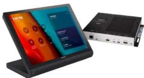
The UC-MM30-T(-I) standard and UC-MMX30-T(-I) advanced (with BYOD functionality) series Crestron Flex tabletop conferencing system provides a small room video conference solution for use with Microsoft Teams® Rooms software. It supports single or dual video displays included).
UC-MM30-T / UC-MM30-T-I UC-MMX30-T / UC-MMX30-T-I
natural_image
Modern tablet device with a camera and screen interface, no visible text or symbols on the device itself.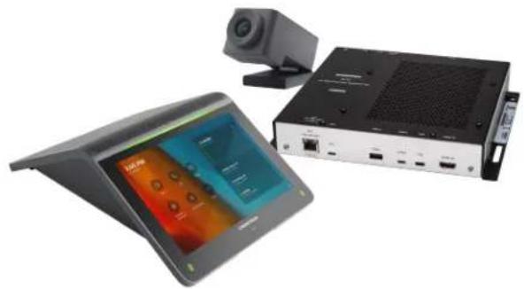
natural_image
Exterior view of a modern office building (no signage)Included Components
| UC-MM30-T(-I) | UC-MMX30-T(-I) | |
| UC-2-T-V | √ | √ |
| CCS-CAM-USB-F-400 | √ | √ |
| UC-CAM-WMK | √ | √ |
| UC-BRKT-200-S-T-ASSY | √ | ✗ |
| UC-BRKT-250-P-T-ASSY or UC-BRKT-260-P-T-ASSY | ✗ | √ |
| UC-PR with Cable Organizer | ✗ | √ |
| Cables | √ | √ |
To view the specifications and dimensions of the included components of the selected kit, refer to Specifications and Dimension Drawings.
Key Features
• Tabletop conferencing solution for Microsoft Teams Rooms environment
- Native Microsoft Teams Rooms touch screen UI provides a consistent user experience with simple operation and one-touch meeting joins
- Optional integration with Crestron control systems
- Direct connection option between UC Engine and Crestron Flex tabletop conference device for simple installation and configuration
• Network management and provisioning, system alerts, and the pairing of the Crestron Flex tabletop conference device to the system's UC Engine through the XiO Cloud service
• Supports single or dual video displays (not included)
- With MMX30 series solutions — present, call, conference, and collaborate using your own device's UC conference platform (BYOD) or the native Microsoft Teams Rooms platform
- Easy to specify and install — no custom design, programming, or software installation required
- Enterprise-grade security — connects and communicates securely over any enterprise or SMB network
- Premium-level support with Crestron Flex Care (optional)
Native Microsoft Teams Rooms Experience
The conferencing solution brings the full Microsoft Teams Rooms UC experience to any meeting space in an enterprise or SMB facility.
Intuitive User Interface with Impressive Audio
With a large 7 in. HD color touch screen and an integrated AEC-enabled USB speakerphone that affords full-duplex wideband audio performance, the mini Crestron Flex Tabletop Conference device provides a superior conferencing and collaboration experience for meeting rooms, huddle spaces, and executive offices.
Simplified Deployment
The UC Bracket Assembly provides preassembled components on one ready-to-mount bracket to simplify installation. The assembly can be mounted on a wall, or it can be attached to the rear of the display device. Crestron's direct connection method further simplifies installation with a single connection from the touch screen to the UC Bracket Assembly.
High-Definition Video Conferencing
The included collaboration camera (CCS-CAM-USB-F-400) features an ultra wide-angle 150° diagonal field of view to capture an entire conference room in Full HD 1080p video resolution. High precision aspherical optics, 12 MP CMOS sensor, and advanced video processing ensure a clear video image free from light or noise artifacts. Genius Framing digital autozoom detects the people in the room and frames them for an optimal view.
Crestron Control System Integration
The conferencing solution can integrate with a Crestron control system to enable touch screen control of room lighting, motorized window shades, climate control, AV, and other amenities.
Bring Your Own Device (offered with MMX series solutions)
Conference room visitors can connect their laptop to the Crestron Flex system to use their own UC conference platform. The UC Presentation Transmitter (UC-PR) switches to the connected laptop's UC platform and returns to the native platform when disconnected. a list of BYOD tested devices on the UC-PR, refer to OLH Article 1000889.
Enterprise-Grade Security
Crestron Flex is an enterprise-grade solution, engineered in partnership with Microsoft to integrate seamlessly into any Microsoft Teams Rooms software deployment. Crestron Flex is ideally equipped for mass deployment throughout any sized corporate, university, medical, military, or government facility.
Easy Provisioning and Device Management
The XiO Cloud service is an IoT cloud based provisioning service (available separately) that enables installers and IT managers to deploy and manage thousands of devices easily. The XiO Cloud service allows for system alerts, network management and provisioning, and the pairing of a control device to the system's UC Engine. System updates are controlled by Windows software update.
Visit www.crestron.com/xiocloud for additional information.
Premium-Level Support
Crestron Flex Care is an optional subscription service that automatically renews annually, providing 24/7 live remote technical support, an extended five year warranty on Crestron hardware, expedited advance replacements, and a discounted rate for on-site support.
Visit www.crestron.com/flexcare for detailed terms and conditions and additional information.
Dual Control Option
A TS- or TSW- 70 series 10.1 in. touch screen may be added to the solution as an additional control po for the Microsoft Teams Rooms environment ^23 .
Deployment Resources
View the Pre-Deployment Checklist on page 223 to help plan your Crestron Flex installation.
Notes:
- Display must support "Wake on Sync" and "Sleep on No Sync" functionality. Consult the display manufacturer's specifications or internal settings of the specific display.
- Room control capability (lighting, shades, thermostats, etc.) requires additional equipment and commissioning to be provided by a Crestron authorized integrator and/or programmer. Additional costs may apply.
- Only one control device may be connected via direct connection method.
- The UC-PR uses a USB-C 2.0 connection to provide content sharing, BYOD support, and charging for a user's device. Because USB-C supports multiple functions, device compatibility often varies. While some devices can accept power and data through the same USB-C connection, others cannot. The USB-C port on the UC-PR (labelled "USB") uses DisplayPort alternate mode for transporting video signals. Consult the connected device's user manual or manufacturer to ensure that the device supports DisplayPort alternate mode. Some devices that support DisplayPort alternate mode may not support device charging. For a list of tested devices, refer to OLH Article 1000889. USB-C transfer speeds may vary based on the connected device's processing speed, system configuration, the operating environment, and/or other factors. If the user's device does not support USB-C, then a combination of HDMI and USB B may be used for content sharing or BYOD functionality. For details, see Connections (UC-MMX30-T).
UC-C100-T and UC-CX100-T Series Features
The UC-C100-T standard and UC-CX100-T advanced (with BYOD functionality) series Crestron Flex integrator kit provides a customizable video conference solution for use with Microsoft Teams® Rooms software. It supports single or dual video display (not included).
text_image
3:00 PM To Be Downloads Now Call Show Take call to meeting U Remote checklist More Available Now - 3:00 PM Weekly Status Call 3:30 PM - 4:30 PM > Forecasting Call 6:30 PM - 5:00 PM > Available 5:00 PM - 12:00 AM CHEMISTRYUC-CX100-T UC-CX100-T-WM
natural_image
Exterior view of a modern office building (no signage)
text_image
3:00 PM Available Analog Audio Signal Call Audio Signal Audio Signal Call Audio Signal Audio SignalIncluded Components
| UC-C100-T | UC-C100-T-WM | UC-CX100-T | UC-CX100-T-WM | |
| TS-1070-B-S-T-V | √ | × | √ | × |
| TSW-1070-B-S-T-V | × | √ | × | √ |
UC-BRKT-200-S-T-ASSY
UC-BRKT-260-P-T-ASSY
UC-PR with Cable Organizer
PoE Injector
Cables
To view the specifications and dimensions of the included components of the selected kit, refer to Specifications and Dimension Drawings.
Key Features
- Conferencing integration solution for Microsoft Teams Rooms software
- Native Microsoft Teams Rooms touch screen UI provides a consistent user experience with simple operation and one-touch meeting joins
- Supports Shure® IntelliMix® Room DSP software (offered with UC-C100-T and UC-C100-T-WM)
- Optional integration with Crestron control systems
- Direct connection option between UC Engine and touch screen for simple installation and configuration
- Network management and provisioning, system alerts, and the pairing of the touch screen to the system's UC Engine through the XiO Cloud service
• Supports single or dual video displays (not included) - With CX100 series solutions — Present, call, conference, and collaborate using your own device's UC conference platform (BYOD) or the native Microsoft Teams Rooms platform
- Enterprise-grade security — connects and communicates securely over any enterprise or SMB network
- Premium-level support with Crestron Flex Care (optional)
Native Microsoft Teams Rooms Experience
The conferencing solution brings the full Microsoft Teams Rooms UC experience to any meeting space in an enterprise or SMB facility.
Custom Room Integration
The conferencing solution system provides the essential components needed to design a fully custom video conferencing space using your choice of display devices, cameras, speakers, microphones, and other AV equipment. Any Microsoft Teams software compliant USB camera and USB audio conferencing interface (or speakerphone) may be used.
Intuitive User Interface
With a large 10.1 in. (257 mm) capacitive touch screen display, the Crestron tabletop or wall mount touch scree provides superior conferencing control in meeting rooms, huddle spaces, and executive offices. The touch screen also offers optional control of room lighting, shades, thermostats, and other equipment. ^2
Using the bracket provided with the wall mount touch screen, the touch screen is easily installed over a 2-gang or 3-gang US electrical box, or a 2-gang European or UK electrical box. A security latch option is included to deter unauthorized removal of the touch screen.
Simplified Deployment
The UC Bracket Assembly provides preassembled components on one ready-to-mount bracket to simplify installation. The assembly can be mounted on a wall, or it can be attached to the rear of the display device. Crestron's direct connection method further simplifies installation with a single connection from the touch screen to the UC Bracket Assembly.
Crestron Control System Integration
The conferencing solution can integrate with a Crestron control system to enable touch screen control of room lighting, motorized window shades, climate control, AV, and other amenities.
Bring Your Own Device (offered with CX series solutions)
Conference room visitors can connect their laptop to the Crestron Flex system to use their own UC conference platform. The UC Presentation Transmitter (UC-PR) switches to the connected laptop's UC platform and returns to the native platform when disconnected. a list of BYOD tested devices on the UC-PR, refer to OLH Article 1000889.
Shure® IntelliMix® Room Integration (offered with UC-C100-T and UC-C100-T-WM)
The conferencing solution supports Shure IntelliMix R ^5 digital signal processing (DSP) software to enable integration with custom audio components such as networked microphones and power amplifiers.
IntelliMix Room integrates seamlessly with the conferencing solution and runs on the UC Engine as conferencing software with no additional hardware requirements.
Enterprise-Grade Security
Crestron Flex is an enterprise-grade solution, engineered in partnership with Microsoft to integrate seamlessly into any Microsoft Teams Rooms software deployment. Crestron Flex is ideally equipped for mass deployment throughout any sized corporate, university, medical, military, or government facility.
Easy Provisioning and Device Management
The XiO Cloud service is an IoT cloud based provisioning service (available separately) that enables installers and IT managers to deploy and manage thousands of devices easily. The XiO Cloud service allows for system alerts, network management and provisioning, and the pairing of a control device to the system's UC Engine. System updates are controlled by Windows software update.
Visit www.crestron.com/xiocloud for additional information.
Premium-Level Support
Crestron Flex Care is an optional subscription service that automatically renews annually, providing 24/7 live remote technical support, an extended five year warranty on Crestron hardware, expedited advance replacements, and a discounted rate for on-site support.
Visit www.crestron.com/flexcare for detailed terms and conditions and additional information.
Dual Control Option
A TS- or TSW- 70 series 10.1 in. touch screen may be added to the solution as an additional control po for the Microsoft Teams Rooms environment ^23 .
Deployment Resources
View the Pre-Deployment Checklist on page 223 to help plan your Crestron Flex installation.
Notes:
- Display must support "Wake on Sync" and "Sleep on No Sync" functionality. Consult the display manufacturer's specifications or internal settings of the specific display.
- Room control capability (lighting, shades, thermostats, etc.) requires additional equipment and commissioning to be provided by a Crestron authorized integrator and/or programmer. Additional costs may apply.
- A maximum of two touch screens or one touch screen and one Crestron Mercury device can be accommodated by the system. Only one control device may be connected via direct connection method.
- The UC-PR uses a USB-C 2.0 connection to provide content sharing, BYOD support, and charging for a user's device. Because USB-C supports multiple functions, device compatibility often varies. While some devices can accept power and data through the same USB-C connection, others cannot. The USB-C port on the UC-PR (labelled "USB") uses DisplayPort alternate mode for transporting video signals. Consult the connected device's user manual or manufacturer to ensure that the device supports DisplayPort alternate mode. Some devices that support DisplayPort alternate mode may not support device charging. For a list of tested devices, refer to OLH Article 1000889. USB-C transfer speeds may vary based on the connected device's processing speed, system configuration, the operating environment, and/or other factors. If the user's device does not support USB-C, then a combination of HDMI and USB B may be used for content sharing or BYOD functionality. For details, see Connections (UC-CX100-T).
- For detailed instructions on planning, deploying, and managing Shure IntelliMix Room, refer to Shure's documentation.
UC-M50-T and UC-MX50-T Features
The UC-M50-T standard and UC-MX50-T advanced (with BYOD functionality) Crestron Flex tabletop conferencing system provides a medium room video conference solution for use with Microsoft Teams® Rooms software. It supports single or dual video displays included).
UC-M50-T UC-MX50-T
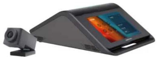
natural_image
Exterior view of a modern office building (no signage)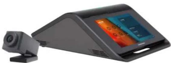
natural_image
Exterior view of a black electronic device with a camera and display screen (no visible text or symbols)Included Components
| UC-M50-T | UC-MX50-T | |
| CCS-UC-1-T-V | √ | ✗ |
| CCS-UC-1-X-T-V | ✗ | √ |
| CCS-CAM-USB-F-400 | √ | √ |
| UC-CAM-WMK | √ | √ |
| PW-2420RU | √ | ✗ |
| UC-BRKT-200-S-T-ASSY | √ | ✗ |
| UC-BRKT-250-P-T-ASSY or UC-BRKT-260-P-T-ASSY | ✗ | √ |
| Cables | √ | √ |
To view the specifications and dimensions of the included components of the selected kit, refer to Specifications and Dimension Drawings.
Key Features
• Tabletop video conferencing solution for Microsoft Teams Rooms environment
- Native Microsoft Teams Rooms touch screen UI provides a consistent user experience with simple operation and one-touch meeting joins
- Optional integration with Crestron control systems
- Direct connection option between UC Engine and Crestron Flex tabletop conference device for simple installation and configuration
- Network management and provisioning, system alerts, and the pairing of the Crestron Flex tabletop conference device to the system's UC Engine through the XiO Cloud service
• Supports single or dual video displays (not included)
- With MX50 series solutions — present, call, conference, and collaborate using your own device's UC conference platform (BYOD) or the native Microsoft Teams Rooms platform
- Easy to specify and install — no custom design, programming, or software installation required
- Enterprise-grade security — connects and communicates securely over any enterprise or SMB network
- Premium-level support with Crestron Flex Care (optional)
Native Microsoft Teams Rooms Experience
The conferencing solution brings the full Microsoft Teams Rooms UC experience to any meeting space in an enterprise or SMB facility.
Intuitive User Interface with Impressive Audio
With a large 7 in. HD color touch screen and an integrated AEC-enabled USB speakerphone that affords full-duplex wideband audio performance, the Crestron Flex Tabletop Conference device provides a superior conferencing and collaboration experience for meeting rooms, huddle spaces, and executive offices. The conference device also offers optional control of room lighting, shades, thermostats, and other equipment ^2 .
Simplified Deployment
The UC Bracket Assembly provides preassembled components on one ready-to-mount bracket to simplify installation. The assembly can be mounted on a wall, or it can be attached to the rear of the display device. Crestron's direct connection method further simplifies installation with a single connection from the touch screen to the UC Bracket Assembly.
High-Definition Video Conferencing
The included collaboration camera (CCS-CAM-USB-F-400) features an ultra wide-angle 150° diagonal field of view to capture an entire conference room in Full HD 1080p video resolution. High precision aspherical optics, 12 MP CMOS sensor, and advanced video processing ensure a clear video image free from light or noise artifacts. Genius Framing digital autozoom detects the people in the room and frames them for an optimal view.
Crestron Control System Integration
The conferencing solution can integrate with a Crestron control system to enable touch screen control of room lighting, motorized window shades, climate control, AV, and other amenities.
Bring Your Own Device (offered with MX series solutions)
Conference room visitors can connect their laptop to the Crestron Flex system to use their own UC conference platform. The system's built-in content ingest device switches to the connected laptop's UC platform and returns to the native platform when disconnected.
Enterprise-Grade Security
Crestron Flex is an enterprise-grade solution, engineered in partnership with Microsoft to integrate seamlessly into any Microsoft Teams Rooms software deployment. Crestron Flex is ideally equipped for mass deployment throughout any sized corporate, university, medical, military, or government facility.
Easy Provisioning and Device Management
The XiO Cloud service is an IoT cloud based provisioning service (available separately) that enables installers and IT managers to deploy and manage thousands of devices easily. The XiO Cloud service allows for system alerts, network management and provisioning, and the pairing of a control device to the system's UC Engine. System updates are controlled by Windows software update.
Visit www.crestron.com/xiocloud for additional information.
Premium-Level Support
Crestron Flex Care is an optional subscription service that automatically renews annually, providing 24/7 live remote technical support, an extended five year warranty on Crestron hardware, expedited advance replacements, and a discounted rate for on-site support.
Visit www.crestron.com/flexcare for detailed terms and conditions and additional information.
Dual Control Option
A TS- or TSW- 70 series 10.1 in. touch screen may be added to the solution as an additional control po for the Microsoft Teams Rooms environment ^23 .
Deployment Resources
View the Pre-Deployment Checklist on page 223 to help plan your Crestron Flex installation.
Note:
- Display must support "Wake on Sync" and "Sleep on No Sync" functionality. Consult the display manufacturer's specifications or internal settings of the specific display.
- Room control capability (lighting, shades, thermostats, etc.) requires additional equipment and commissioning to be provided by a Crestron authorized integrator and/or programmer. Additional costs may apply.
- A maximum of two touch screens or one touch screen and one Crestron Mercury device can be accommodated by the system. Only one control device may be connected via direct connection method.
UC-M50-T-UPGRD and UC-MX50-T-UPGRD Features
The UC-M50-T-UPGRD standard and UC-MX50-T-UPGRD solution provides all of the necessary components to upgrade a deployed Crestron Flex tabletop conference device and camera to a complete video conference system for use with the Microsoft Teams Rooms intelligent communications platform. It supports single or dual video display (not included).
UC-M50-T-UPGRD UC-MX50-T-UPGRD
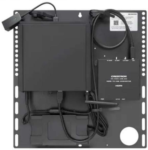
natural_image
Front view of a black electronic device with cables, connectors, and a CRESTRON HORN device (no visible text or symbols on main body)
natural_image
Front view of a black rack-mounted electronic device with connected cables and a central control unit (no visible text or symbols)Included Components
| UC-M50-T-UPGRD | UC-MX50-T-UPGRD | |
| UC-BRKT-200-S-T-ASSY | √ | ✗ |
| UC-BRKT-250-P-T-ASSY or UC-BRKT-260-P-T-ASSY | ✗ | √ |
| Cables | √ | √ |
To view the specifications and dimensions of the included components of the selected kit, refer to Specifications and Dimension Drawings.
Key Features
- Upgrades a single Crestron Flex tabletop conference device to a complete video conference system
- Native Microsoft Teams Rooms touch screen UI provides a consistent user experience with simple operation and one-touch meeting joins
-
Optional integration with Crestron control systems
-
Direct connection option between UC Engine and Crestron Flex tabletop conference device for simple installation and configuration
- Network management and provisioning, system alerts, and the pairing of the Crestron Flex tabletop conference device to the system's UC Engine through the XiO Cloud service
• Supports single or dual video displays - With MX50 upgrade series solutions — present, call, conference, and collaborate using your own device's UC conference platform (BYOD) or the native Microsoft Teams Rooms platform
- Easy to specify and install — no custom design, programming, or software installation required
- Enterprise-grade security — connects and communicates securely over any enterprise or SMB network
- Premium-level support with Crestron Flex Care (optional)
Native Microsoft Teams Rooms Experience
The conferencing solution brings the full Microsoft Teams Rooms UC experience to any meeting space in an enterprise or SMB facility.
Bring Your Own Device (offered with MX series solutions)
Conference room visitors can connect their laptop to the Crestron Flex system to use their own UC conference platform. The system's built-in content ingest device switches to the connected laptop's UC platform and returns to the native platform when disconnected.
Simplified Deployment
The UC Bracket Assembly provides preassembled components on one ready-to-mount bracket to simplify installation. The assembly can be mounted on a wall, or it can be attached to the rear of the display device. Crestron's direct connection method further simplifies installation with a single connection from the touch screen to the UC Bracket Assembly.
Crestron Control System Integration
The conferencing solution can integrate with a Crestron control system to enable touch screen control of room lighting, motorized window shades, climate control, AV, and other amenities.
Enterprise-Grade Security
Crestron Flex is an enterprise-grade solution, engineered in partnership with Microsoft to integrate seamlessly into any Microsoft Teams Rooms software deployment. Crestron Flex is ideally equipped for mass deployment throughout any sized corporate, university, medical, military, or government facility.
Easy Provisioning and Device Management
The XiO Cloud service is an IoT cloud based provisioning service (available separately) that enables installers and IT managers to deploy and manage thousands of devices easily. The XiO Cloud service allows for system alerts, network management and provisioning, and the pairing of a control device to the system's UC Engine. System updates are controlled by Windows software update.
Visit www.crestron.com/xiocloud for additional information.
Premium-Level Support
Crestron Flex Care is an optional subscription service that automatically renews annually, providing 24/7 live remote technical support, an extended five year warranty on Crestron hardware, expedited advance replacements, and a discounted rate for on-site support.
Visit www.crestron.com/flexcare for detailed terms and conditions and additional information.
Dual Control Option
A TS- or TSW- 70 series 10.1 in. touch screen may be added to the solution as an additional control po for the Microsoft Teams Rooms environment ^23 .
Deployment Resources
View the Pre-Deployment Checklist on page 223 to help plan your Crestron Flex installation.
Notes:
- Display must support "Wake on Sync" and "Sleep on No Sync" functionality. Consult the display manufacturer's specifications or internal settings of the specific display.
- A maximum of two touch screens or one touch screen and one Crestron Mercury device can be accommodated by the system. Only one control device may be connected via direct connection method.
- Room control capability (lighting, shades, thermostats, etc.) requires additional equipment and commissioning to be provided by a Crestron authorized integrator and/or programmer. Additional costs may apply.
UC-M70-T and UC-MX70-T Features
The UC-M70-T standard and UC-MX70-T advanced (with BYOD functionality) Crestron Flex advanced tabletop conferencing system provides a large room video conference solution for use with Microsoft Teams® Rooms software. It supports single or dual video displays included).
UC-M70-T UC-MX70-T
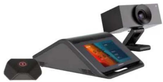
natural_image
Exterior view of a modern office building (no signage)
natural_image
Exterior view of a modern office building (no signage)Included Components
| UC-M70-T | UC-MX70-T | |
| CCS-UC-1-T-V | √ | ✗ |
| CCS-UC-1-X-T-V | ✗ | √ |
| UC-CAM-L1 | √ | √ |
| CCS-UCA-MIC | √ | √ |
| PW-2420RU | √ | ✗ |
| UC-BRKT-200-S-T-ASSY | √ | ✗ |
| UC-BRKT-250-P-T-ASSY or UC-BRKT-260-P-T-ASSY | ✗ | √ |
| Cables | √ | √ |
To view the specifications and dimensions of the included components of the selected kit, refer to Specifications and Dimension Drawings.
Key Features
• Tabletop video conferencing solution for Microsoft Teams Rooms environment
- Native Microsoft Teams Rooms touch screen UI provides a consistent user experience with simple operation and one-touch meeting joins
- Optional integration with Crestron control systems
- Direct connection option between UC Engine and Crestron Flex tabletop conference device for simple installation and configuration
• Network management and provisioning, system alerts, and the pairing of the Crestron Flex tabletop conference device to the system's UC Engine through the XiO Cloud service
• Supports single or dual video displays (not included)
- With MX70 series solutions — present, call, conference, and collaborate using your own device's UC conference platform (BYOD) or the native Microsoft Teams Rooms platform
- Easy to specify and install — no custom design, programming, or software installation required
- Enterprise-grade security — connects and communicates securely over any enterprise or SMB network
- Premium-level support with Crestron Flex Care (optional)
Native Microsoft Teams Rooms Experience
The conferencing solution brings the full Microsoft Teams Rooms UC experience to any meeting space in an enterprise or SMB facility.
Intuitive User Interface with Impressive Audio
With a large 7 in. HD color touch screen and an integrated AEC-enabled USB speakerphone that affords full-duplex wideband audio performance, the Crestron Flex Tabletop Conference device provides a superior conferencing and collaboration experience for meeting rooms, huddle spaces, and executive offices. The conference device also offers optional control of room lighting, shades, thermostats, and other equipment ^2 .
Simplified Deployment
The UC Bracket Assembly provides preassembled components on one ready-to-mount bracket to simplify installation. The assembly can be mounted on a wall, or it can be attached to the rear of the display device. Crestron's direct connection method further simplifies installation with a single connection from the touch screen to the UC Bracket Assembly.
High-Definition Video Conferencing
The included AI collaboration camera (UC-CAM ^4 ) features a wide-angle 103° diagonal field of view to capture an entire conference room in Full HD 1080p video resolution. High precision aspherical optics, 20.30 MP CMOS sensor, and advanced video processing ensure a clear video image free from light or noise artifacts. Genius Framing digital autozoom intelligently detects the people in the room and frames them for an optimal view.
Crestron Control System Integration
The conferencing solution can integrate with a Crestron control system to enable touch screen control of room lighting, motorized window shades, climate control, AV, and other amenities.
Bring Your Own Device (offered with MX series solutions)
Conference room visitors can connect their laptop to the Crestron Flex system to use their own UC conference platform. The system's built-in content ingest device switches to the connected laptop's UC platform and returns to the native platform when disconnected.
Enterprise-Grade Security
Crestron Flex is an enterprise-grade solution, engineered in partnership with Microsoft to integrate seamlessly into any Microsoft Teams Rooms software deployment. Crestron Flex is ideally equipped for mass deployment throughout any sized corporate, university, medical, military, or government facility.
Easy Provisioning and Device Management
The XiO Cloud service is an IoT cloud based provisioning service (available separately) that enables installers and IT managers to deploy and manage thousands of devices easily. The XiO Cloud service allows for system alerts, network management and provisioning, and the pairing of a control device to the system's UC Engine. System updates are controlled by Windows software update.
Visit www.crestron.com/xiocloud for additional information.
Premium-Level Support
Crestron Flex Care is an optional subscription service that automatically renews annually, providing 24/7 live remote technical support, an extended five year warranty on Crestron hardware, expedited advance replacements, and a discounted rate for on-site support.
Visit www.crestron.com/flexcare for detailed terms and conditions and additional information.
Dual Control Option
A TS- or TSW- 70 series 10.1 in. touch screen may be added to the solution as an additional control po for the Microsoft Teams Rooms environment ^23 .
Deployment Resources
View the Pre-Deployment Checklist on page 223 to help plan your Crestron Flex installation.
Notes:
- Display must support "Wake on Sync" and "Sleep on No Sync" functionality. Consult the display manufacturer's specifications or internal settings of the specific display.
- Room control capability (lighting, shades, thermostats, etc.) requires additional equipment and commissioning to be provided by a Crestron authorized integrator and/or programmer. Additional costs may apply.
- A maximum of two touch screens or one touch screen and one Crestron Mercury device can be accommodated by the system. Only one control device may be connected via direct connection method.
- Applicable for UC-MX70-T: The UC-CAM-L1 with network adapter requires driver installation on the connected laptop. A USB plug-and-play adapter, UC-CAMA-ADPT-ENET-USB, can be purchased separately to avoid driver installation.
UC-M70-NC-T and UC-MX70-NC-T Features
The UC-M70-NC-T standard and UC-MX70-NC-T advanced (with BYOD functionality) Crestron Flex advanced tabletop conferencing system provides a large room video conference solution for use with Microsoft Teams® Rooms software. It supports single or dual video displays included).
UC-M70-NC-T UC-MX70-NC-T

natural_image
Exterior view of a modern office building (no signage)
natural_image
Black electronic device with a digital display and a connected sensor (no visible text or symbols)Included Components
| UC-M70-NC-T | UC-MX70-NC-T | |
| CCS-UC-1-T-V | √ | ✗ |
| CCS-UC-1-X-T-V | ✗ | √ |
| CCS-UCA-MIC | √ | √ |
| PW-2420RU | √ | ✗ |
| UC-BRKT-200-S-T-ASSY | √ | ✗ |
| UC-BRKT-250-P-T-ASSY or UC-BRKT-260-P-T-ASSY | ✗ | √ |
| Cables | √ | √ |
To view the specifications and dimensions of the included components of the selected kit, refer to Specifications and Dimension Drawings.
Key Features
• Supports single or dual video displays (not included)
- With MX70 series solutions — present, call, conference, and collaborate using your own device's UC conference platform (BYOD) or the native Microsoft Teams Rooms platform
- Enterprise-grade security — connects and communicates securely over any enterprise or SMB network
• Premium-level support with Crestron Flex Care (optional)
Native Microsoft Teams Rooms Experience
The conferencing solution brings the full Microsoft Teams Rooms UC experience to any meeting space in an enterprise or SMB facility.
Intuitive User Interface with Impressive Audio
With a large 7 in. HD color touch screen and an integrated AEC-enabled USB speakerphone that affords full-duplex wideband audio performance, the Crestron Flex Tabletop Conference device provides a superior conferencing and collaboration experience for meeting rooms, huddle spaces, and executive offices. The conference device also offers optional control of room lighting, shades, thermostats, and other equipment ^2 .
Simplified Deployment
The UC Bracket Assembly provides preassembled components on one ready-to-mount bracket to simplify installation. The assembly can be mounted on a wall, or it can be attached to the rear of the display device. Crestron's direct connection method further simplifies installation with a single connection from the touch screen to the UC Bracket Assembly.
High-Definition Video Conferencing
High-definition video conferencing can be achieved by utilizing the IV-CAM-P12-B, IV-CAM-P12-W, IV-CAM-P20-B, IV-CAM-P20-W, IV-CAM-I12-B, IV-CAM-I20-B, and IV-CAM-I20-W cameras. Microsoft Teams certified third-party cameras are also compatible with the system.
Crestron Control System Integration
The conferencing solution can integrate with a Crestron control system to enable touch screen control of room lighting, motorized window shades, climate control, AV, and other amenities.
Bring Your Own Device (offered with MX series solutions)
Conference room visitors can connect their laptop to the Crestron Flex system to use their own UC conference platform. The system's built-in content ingest device switches to the connected laptop's UC platform and returns to the native platform when disconnected.
Enterprise-Grade Security
Crestron Flex is an enterprise-grade solution, engineered in partnership with Microsoft to integrate seamlessly into any Microsoft Teams Rooms software deployment. Crestron Flex is ideally equipped for mass deployment throughout any sized corporate, university, medical, military, or government facility.
Easy Provisioning and Device Management
The XiO Cloud service is an IoT cloud based provisioning service (available separately) that enables installers and IT managers to deploy and manage thousands of devices easily. The XiO Cloud service allows for system alerts, network management and provisioning, and the pairing of a control device to the system's UC Engine. System updates are controlled by Windows software update.
Visit www.crestron.com/xiocloud for additional information.
Premium-Level Support
Crestron Flex Care is an optional subscription service that automatically renews annually, providing 24/7 live remote technical support, an extended five year warranty on Crestron hardware, expedited advance replacements, and a discounted rate for on-site support.
Visit www.crestron.com/flexcare for detailed terms and conditions and additional information.
Dual Control Option
A TS- or TSW- 70 series 10.1 in. touch screen may be added to the solution as an additional control po for the Microsoft Teams Rooms environment ^23 .
Deployment Resources
View the Pre-Deployment Checklist on page 223 to help plan your Crestron Flex installation.
Notes:
- Display must support "Wake on Sync" and "Sleep on No Sync" functionality. Consult the display manufacturer's specifications or internal settings of the specific display.
- Room control capability (lighting, shades, thermostats, etc.) requires additional equipment and commissioning to be provided by a Crestron authorized integrator and/or programmer. Additional costs may apply.
- A maximum of two touch screens or one touch screen and one Crestron Mercury device can be accommodated by the system. Only one control device may be connected via direct connection method.
Specifications and Dimension Drawings
Refer to the following sections for more information regarding the specifications and dimensions of the following devices.
Tabletop Conferencing Device Specifications
Device name: CCS-UC-1-T-V / CCS-UC-1-X-T-V
Touch Screen 7 in. (178 mm) diagonal capacitive multi-touch TFT active matrix color LCD, 1280 x 800 pixels
UI Microsoft Teams Rooms UI plus optional Crestron room control UI
Mic Mute Symbol and Light Bar (2) Capacitive buttons with bi-color LEDs, either button toggles between mute and unmute
AEC Limes Audio TrueVoice® acoustic echo cancellation, automatic mic mixing, automatic gain control, and dynamic noise reduction, full-duplex IEEE 1329 Type 1 compliant
Speaker Full range speaker;
Amplifier Power: 11 W; 95 dB SPL at 0.5 m maximum output; Frequency Response: 90 Hz to 22 kHz
Microphones 360° quad mic array; Pickup Range (typical): 20 ft (6 m)
Extension Microphones Supports two mic pods, model CCS-UCA-MIC (sold separately)
Occupancy Sensor 6 ft (1.83 m) PIR range in front of touch screen
Ethernet (CCS-UC-1-TV) 100 Mbps, auto-switching, auto-negotiating, auto-discovery, full/half duplex, DHCP, TCP/IP, UDP/IP, CIP, SSL, TLS, SSH, SFTP (SSH File Transfer Protocol), SRTP, IEEE 802.1X, Active Directory authentication, digest access authentication, password login, XiO Cloud client, Microsoft Intune® client, IEEE 802.3at Type 2 PoE+ compliant
Ethernet (CCS-UC-1-X-T-V) 100 Mbps, auto-switching, autonegotiating, autodiscovery, full/half duplex, DHCP, TCP/IP, UDP/IP, CIP, SSL, TLS, SSH, SFTP (SSH File Transfer Protocol), SRTP, IEEE 802.1X, Active Directory authentication, digest access authentication, password login, XiO Cloud service, Microsoft Intune® client
USB USB 2.0 micro Type B device port, supports UAC for audio interface to UC Engine (cable included)
Power Options (CCS-UC-PoE+: IEEE 802.3at Type 2, Class 4 (25.5 W) PoE+ Powered Device 1-TV)
NOTE: If the additional mic pod (CCS-UCA-MIC) is used, PoE+ cannot be used to power the device.
24VDC: 24VDC via external 100-240VAC, 50/60 Hz power pack, model PW-2420RU
Power (CCS-UC-1-X-T-V) 24VDC via external 100-240VAC, 50/60 Hz power pack, model PW-2420RU
NOTE: The CCS-UC-1-X cannot be powered by Power over Ethernet or PoE+.
Dimensions Height: 4.11 in. (104 mm)
Width: 8.92 in. (227 mm)
Depth: 12.74 in. (324 mm)
Weight 5.5 lb (2.5 kg)
Tabletop Conferencing Device Dimension Drawing

Mini Tabletop Conferencing Device Specifications
Device name: UC-2 / UC-2-T-V
Touch Screen 7 in. (178 mm) diagonal capacitive multi-touch TFT active matrix color LCD, 1280 x 800 pixels
UI (UC-2) Microsoft Teams Audio UI
UI (UC-2-T-V) Microsoft Teams UI
Mic Mute Symbol and (4) Capacitive buttons with bi-color LEDs, toggles between mute and unmute Light Bar
AEC Automatic gain control, dynamic noise reduction, acoustic echo cancellation, full-duplex IEEE 1329 Type 1 compliant
Speaker Full range speaker;
Amplifier Power: 7 W (rated power);
Output Volume: 83 ±3 dBA @1m 1 kHz;
Frequency Response: 100 Hz - 20 kHz
Microphones (4) Built-in omnidirectional, digital MEMS microphones with 360° audio pickup;
Maximum pickup range: 10 ft (3 m) typical
Occupancy Sensor Approx. 10 ft (3 m) PIR range in front of touch screen
Ethernet 100 Mbps, auto-switching, auto-negotiating, auto-discovery, full/half duplex, DHCP, TCP/IP, UDP/IP, CIP, SSL, TLS, SSH, SFTP (SSH File Transfer Protocol), SRTP, IEEE 802.1X, Active Directory® authentication, digest access authentication, password login, XiO Cloud client, Microsoft Intune® client, IEEE 802.3at Type 2 PoE+ compliant
USB USB 2.0 micro Type B device port, supports UAC for audio interface to UC Engine (cable included)
Power IEEE 802.3af Class 3 and 802.3at Class 4 PoE+ powered device;
PoE+ injector included
Dimensions Height: 3.02 in. (77 mm)
Width: 7.17 in. (182 mm)
Depth: 9.61 in. (244 mm)
Weight 2.1 lb (0.96 kg)
Mini Tabletop Conferencing Device Dimension Drawing
Tabletop and Wall Mount Touch Screen Specifications
Device name: TS-1070-B-S-T-V / TSW-1070-B-S-T-V
Touch Screen
10.1 in. (257 mm) diagonal capacitive multi-touch TFT active matrix color LCD, 1920 x 1200 pixels
UI Microsoft Teams UI plus optional Crestron Smart Graphics® room control UI
Ethernet 100/1000 Mbps, auto switching, auto negotiating, auto discovery, full/half duplex, TCP/IP, UDP/IP, CIP, DHCP, SSL, TLS, SSH, SFTP (SSH File Transfer Protocol), IEEE 802.1X, SNMP, IPv4 or IPv6, Active Directory® service authentication, HTTPS web browser setup, XiO Cloud® client, IEEE 802.3at compliant
Power over Ethernet IEEE 802.3at Type 2 compliant PoE+ PD (Powered Device);
Normally requests 15 W from an 802.3at Type 2 PSE with LLDP advanced power management;
With room scheduling and USB enabled, requests 18 W from an 802.3at Type 2 PSE with LLDP;
Requests 30 W (PoE+ Class 4) from an 802.3at Type 2 PSE without LLDP;
Requests 15.4 W (PoE Class 0) from an 802.3af (or 802.3at Type 1) PSE
Power Powered via PoE passthrough on the UC-PR
Construction Plastic, smooth black finish, edge-to-edge glass with black surround
Dimensions (TS-
Height: 5.29 in. (134 mm)
1070-B-S-T-V)
Width: 9.63 in. (245 mm)
Depth: 4.67 in. (119 mm)
Dimensions (TSW-
Height: 5.87 in. (149 mm)
1070-B-S-T-V)
Width: 9.46 in. (240 mm)
Depth: 2.01 in. (51 mm)
Dimensions do not include mounting bracket or add-on accessories
Weight (TS-
2.44 lb (1105 g)
1070-B-S-T-V)
Weight (TSW-
1.61 lb (730 g)
1070-B-S-T-V)
Tabletop Touch Screen Dimension Drawing
TS-1070-B-S-T-V
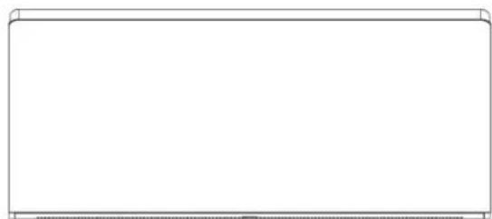
natural_image
Blank white rectangular frame with a curved top edge (no text or symbols)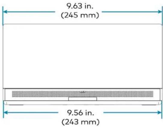
text_image
9.63 in. (245 mm) 9.56 in. (243 mm)
natural_image
Top-down schematic of a device rear panel with internal components and mounting holes (no text or labels)
text_image
5.29 in. (134 mm) 3.87 in. (98 mm) 4.67 in. (119 mm)Wall Mount Touch Screen Dimension Drawing
TSW-1070-B-S-T-V

text_image
3.42 in. (87 mm) 3.02 in. (77 mm) 2.66 in. (68 mm) 0.58 in. (15 mm) 2.01 in. (51 mm) 5.87 in. (149 mm) 9.46 in. (240 mm) 1.66 in. (42 mm) 1.85 in. (47 mm) 2.01 in. (51 mm)Wall Mount Touch Screen Bracket Dimension Drawing

Smart Soundbar and Camera Specifications
UC-SB1-CAM-FLEX
| Speakers Stereo 2-way, 20 W per channel; |
| 3 in. (76 mm) woofers; |
| 3 x 4-3/8 in. (76 x 112 mm) passive radiators; |
| 1 in. (25 mm) dome tweeters; |
| 80 Hz to 20 kHz ( ± 3 dB) frequency response; |
| 91 dB SPL @ 1 m output level (both channels driven at full power) |
| Microphone Linear quad-element far-field adaptive beamforming microphone array;15 ft (4.6 m) pickup range, 180° horizontal and 180° vertical pickup angle;20 Hz to 8 kHz frequency response |
NOTE: Microphone pickup range may vary in rooms with highly reflective infrastructure (e.g., glass walls, metal furniture, open ceilings, etc.) or above average ambient noise.
| Audio DSP Acoustic echo cancellation, dereverberation, automatic gain control, dynamic noise suppression, adaptive beamforming, speaker volume control, speaker EQ and limiting (fixed);Full-duplex IEEE 1329 Type 1 compliant | |
| Camera Optics | 12 Megapixel 1/2.3 CMOS sensor, ultra wide angle six element aspherical glass lens,f/2.8 aperture |
| Camera Field of View 150° diagonal, 120° horizontal, 90° vertical | |
| Autozoom Genius Framing automatic lossless digital zoom intelligently frames around people in the room | |
| Camera Noise Reduction | 3D noise reduction, bias compensating spatio-temporal filtering, wide area chroma filtering, flicker elimination |
| Camera Scaling Real-time scaling, dewarping, and perspective correction | |
| Camera Resolution HD 1080p @ 30 fps | |
| Analog Audio Input | 2-Channel stereo via 3.5 mm TRS mini-phone jack, fixed level (bypasses DSP), 1 Vrms maximum per channel for full rated output, for in-room amplification of an external audio source |
| Analog Audio Output | 2-Channel stereo via 3.5 mm TRS mini-phone jack, fixed level, 1 Vrms maximum, feeds amplified audio content to an assistive listening system |
| Status Bar | Multi-segment RGBY LED zero-center mutually-diverging linear bargraph |
| Main Power | 24VDC via external 100-240VAC, 50/60 Hz power pack, model PW-2420RU (included) |
| Enclosure | Lightly textured gunmetal black finish, plastic housing, perforated stainless steel grilles, die-cast aluminum rear cover, integral steel hinged mounting bracket |
| Mounting | Freestanding or surface wall mount at ear/face level (adhesive feet included,mounting bracket attached) |
| Dimensions | Height: 4.57 in. (116 mm), 4.64 in. (118 mm) with feetWidth: 43.60 in. (1107 mm)Depth: 3.90 in. (99 mm) |
| Weight | 13.56 lb (6.2 kg) |
UC-SB1-CAM-FLEX Dimension Drawing
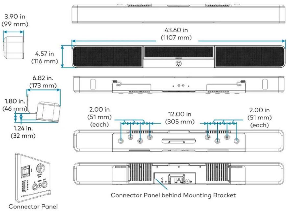
text_image
3.90 in (99 mm) 43.60 in (1107 mm) 4.57 in (116 mm) 6.82 in. (173 mm) 1.80 in. (46 mm) 1.24 in. (32 mm) 2.00 in (51 mm) (each) 12.00 in (305 mm) each 2.00 in (51 mm) (each) Connector Panel behind Mounting Bracket Connector PanelUC-SB-P50 or UC-SB-P50-INDIA
Speakers (4) speakers, stereo;
2 in. (50 mm) woofers;
2 x 3/4 in. (50 x 20 mm) tweeters;
80 Hz to 20 kHz frequency response;
Automatic speaker detection
Microphone (8) microphone beamforming array;
-37 dBFS microphone sensitivity;
100 Hz to 8 kHz microphone frequency range;
Suitable for rooms up to 15 x 15 ft (4.5 x 4.5 m)
NOTE: Microphone pickup range may vary in rooms with highly reflective infrastructure (e.g., glass walls, metal furniture, open ceilings, etc.) or above average ambient noise.
Camera Optics (3) cameras;
13 Megapixels
Camera Field of View 180° horizontal, 54° vertical
Autozoom Automatic digital zoom dynamically frames people within 11 ft (3.5 m)
Camera Resolution 3840 x 1080 @ 30 fps
Power From external power pack;
Input: 100-240VAC, 50/60 Hz;
Output: 5A @ 12V
Enclosure Black speaker and camera housing, rear air vents, integrated adjustable mounting bracket
Mounting Wall mount using integrated mounting bracket;
Optional table mount or VESA® compliant screen mount (both sold separately)
Dimensions Height: 3.1 in. (90 mm)
Width: 25.60 in. (650 mm)
Depth: 4.90 in. (125 mm)
Weight 4.85 lb (2.2 kg)
For more information on the Jabra PanaCast 50 video bar for Crestron Flex systems, refer to jabra.com/panacast50.
Camera Specifications
CCS-CAM-USB-F-400
Image Sensor 12 Megapixel 1/2.3 CMOS sensor
Lens High precision, ultra wide angle, six element aspherical glass lens
Field of View 150° diagonal, 120° horizontal, 90° vertical
Aperture f/2.8
Autozoom Genius Framing automatic lossless digital zoom intelligently frames around people in the room
Connectivity Plug-and-play USB 3.1
Resolution/FPS HD 1080p @ 30 fps
Dimensions Height: 1.40 in. (36 mm)
Width: 1.60 in. (41 mm)
Depth: 2.82 in. (72 mm)
Weight 4.2 oz (120 g)
UC-CAM-L1
Image Sensor 20.30 Megapixels 1 in. CMOS Sensor
Lens High precision, wide angle, aspherical glass lens
Field of View 103° diagonal, 92° horizontal, 65° vertical
Aperture f/2.9
Autozoom Genius Framing automatic lossless digital zoom intelligently frames around people in the room
Connectivity USB 3.0 port (via USB to PoE Adapter)
Power 5VDC power adapter
Resolution/FPS HD 1080p @ 30 fps
Dimensions Height: 2.1 in. (53 mm)
Width: 4.8 in. (122 mm)
Depth: 3.5 in. (89 mm)
Weight 1.3 lb (0.6 kg)
UC Engine Bracket Assembly Specifications
Device name: UC-BRKT-200-S-T-ASSY / UC-BRKT-250-P-T-ASSY / UC-BRKT-260-P-T-ASSY
UC Engine Mini PC, Intel Core® processor with Windows® 10 IoT Edition OS and 100/1000 Mbps Ethernet connectivity
UC Client Microsoft Teams Rooms
Management Client XiO Cloud Service
Content Ingest HDMI input via HDMI to USB 3.0 converter (UC-BRKT-200-S-T-ASSY)
Content Ingest HDMI input via CAT5 to USB 3.0 converter (UC-BRKT-250-P-T-ASSY or UC-BRKT-260-P-T-ASSY)
NOTE: Use only DigitalMedia™ Ultra cable between the conference and content ingest devices (UC-BRKT-250-P-T-ASSY). The maximum supported cable length is 300 ft.
Display Output Single or dual displays support
Display Output Resolution 1080p
Power (UC-BRKT-200-S-130 W via external 100-240VAC, 50/60 Hz adapter (included) T-ASSY)
Power (UC-BRKT-250-P- UC Engine: 100-240VAC, 50/60 Hz adapter (included);
T-ASSY / UC-BRKT-260-P-T-ASSY) Content ingest device: 24VDC via external 100-240VAC, 50/60 Hz power pack (included)
Construction Metal mounting bracket, black, preassembled with UC Engine and content ingest device
Mounting Surface wall mount behind the display device, or attach to the rear of the display device via the bolts attaching the display to a VESA® compliant display mount; Bracket includes mounting holes on both side edges, spaced 100, 200, and 300 mm vertically, to allow for attachment to either side of the display mounting plate
Dimensions Maximum Height: 15.00 in. (381 mm) Maximum Width: 14.50 in. (368 mm) Maximum Depth: 1.93 in. (49 mm)
Maximum Weight 8.0 lb (3.7 kg)
UC Engine Bracket Assembly Dimension Drawing
UC-BRKT-200-S-T-ASSY
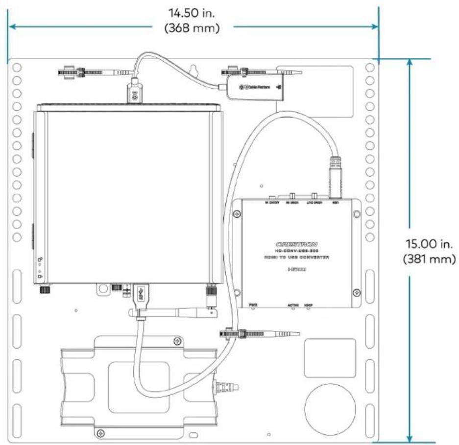
text_image
14.50 in. (368 mm) 15.00 in. (381 mm)
text_image
1.93 in. (49 mm)UC-BRKT-250-P-T-ASSY

text_image
14.50 in. (368 mm) 13.80 in. (351 mm) 6.90 in. (175 mm) 15.00 in. (381 mm) 14.30 in. (363 mm) 13.35 in. (339 mm) 14.36 in. (365 mm) 5.35 in. (136 mm) 1.72 in. (44 mm)UC-BRKT-260-P-T-ASSY

text_image
14.50 in. (368 mm) 15.00 in. (381 mm) 1.87 in. (48 mm)UC Presentation Transmitter Specifications
Video Input Signal Types HDMI, DisplayPort™ 1.2 via USB-C® port
Video Output Signal Types HDMI over CAT5
Resolution 1080p
Video Content Protection HDCP 1.4 and HDCP 2.2
Audio Input Signal Types HDMI, DisplayPort 1.2 via USB-C port
Audio Output Signal Types HDMI over CAT5
Communications Ethernet: 100 Mbps, auto-switching, auto negotiating, auto-discovery
HDMI over CAT5: HDCP, Ethernet
HDMI: HDCP
USB: USB 2.0 and USB 3.0
Connectors LAN PoE: (1) 8-pin RJ-45 connector;
ACC: (1) USB 3.0 Type B connector;
For firmware loading only;
USB A: (1) USB 2.0 Type A connector;
USB B: (1) USB 2.0 Type B connector;
USB: (1) USB 2.0 Type-C connector;
HDMI IN: (1) HDMI Type A;
To RX: (1) 8-pin RJ-45 connector;
Power Jack: (1) DC power connector;
LAN: (1) 8-pin RJ-45 connector;
Ground: (1) 6-32 screw
Indicators PWR: (1) Green LED, indicates operating power supplied via power supply
Ethernet: (2) LEDs on To RX port;
Green indicates Ethernet link status;
Amber indicates Ethernet activity
Power Supply 24VDC, 6A, 100-240VAC
Device Charging Up to 60 W charging for devices connected via USB-C port
Construction Metal, black finish, integral mounting flanges;
Vented top, front, bottom, and sides
Mounting Surface mount for mounting under table;
Attaches to a single rack rail
Dimensions Height: 1.58 in. (40 mm)
Width: 9.25 in. (235 mm)
Depth: 8.20 in. (208 mm)
UC Presentation Transmitter Dimension Drawing
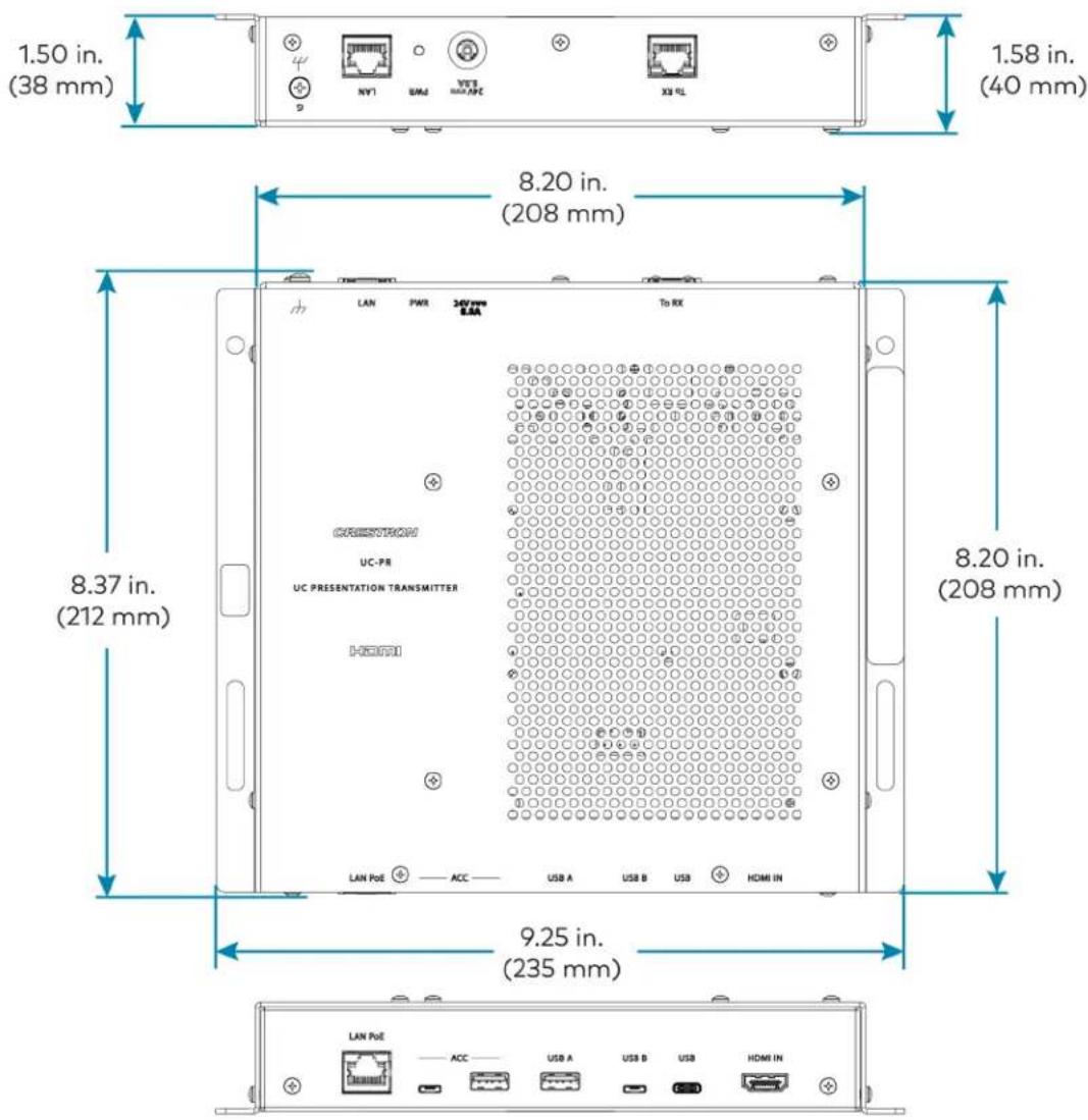
text_image
1.50 in. (38 mm) 1.58 in. (40 mm) 8.20 in. (208 mm) 8.37 in. (212 mm) 9.25 in. (235 mm)Microphone Pod Specifications
Model CCS-UCA-MIC
Communications A2B bus protocol, slave, synchronous data, multichannel I2S/TDM to I2S/TDM
Microphone Triple mic array with (3) cardioid electret elements
Pickup Range 20 ft (6 m) typical, 360°
Mic Mute (1) Capacitive button with bi-color LED, toggles between mute and unmute (affects all system mics)
Connectors (2) RJ9 4P4C connector, female
Power Powered via the conference device through the A2B bus
Dimensions Height: 0.97 in (25 mm)
Width: 3.81 in (97 mm)
Depth: 3.42 in (87 mm)
Microphone Pod Dimension Drawing

Installation and Connections
Refer to the following instructions to correctly install and connect various Microsoft Teams Rooms solutions.
- To install and connect the UC-MM30-TA and UC-MM30-TA-I audio conferencing solution, select UC-MM30-TA and UC-MM30-TA-I Installation on page 219.
- To install and connect B30/BX30, C100/CX100, MM30/MMX30, M50/MX50, and M70/MX70 series solutions powered by the UC Engine (mini PC attached to the UC Engine Bracket Assembly):
- Identify the UC Engine model included with your Crestron Flex solution.
NOTE: The UC Engine is available in various models. Therefore, identify the included UC Engine model before installing the selected room solution and making system connections.
- Dell UC Engine

natural_image
Technical line drawing of a server rack front panel with ports and connectors (no text or symbols)- ASUS UC Engine
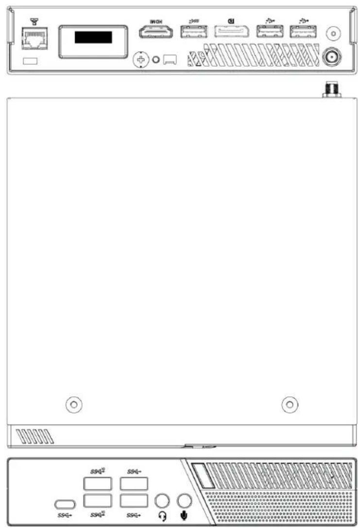
text_image
Technical diagram of a server rack with front panel, rear panel, and internal control panel showing ports like I/OH, I/O, and SS2.- Lenovo UC Engine (Discontinued)

text_image
Lenovo Lenovo- Once Identified, refer to the following sections for installing the devices and making system connections.
• Installing Microsoft Teams Rooms Solutions Powered by Dell UC Engine.
- Installing Microsoft Teams Rooms Solutions Powered by ASUS UC Engine.
Refer to Discontinued Solutions on page 584 to install and connect the discontinued Microsoft Teams or Zoom Rooms solutions (including solutions powered by the discontinued Lenovo UC Engine).
Installing Microsoft Teams Rooms Solutions Powered by Dell UC Engine
- Ensure you have received all the items mentioned in the In the Box section for your selected Crestron Flex solution.
- Mount all the devices applicable to your selected conferencing solution. For details, refer to Mounting Devices.
- Make connections for your selected conferencing solution. For details, refer to Connections.
In the Box
This section provides the following information:
In the Box (UC-B30-T and UC-B30-T-WM)
| Qty. Description | UC-B30-T | UC-B30-T-WM | |
| Tabletop Touch Screen | |||
| 1 10.1 | in. Tabletop Touch Screen (6511748) | √ | ✕ |
| 1 Grommet, Cable, Closed (2055455) | |||
| 1 Grommet, Cable, Open (2055456) | |||
| 1 Cover, Cable compartment (2055457) | |||
| Wall Mount Touch Screen | |||
| 1 10.1 | in. Wall Mount Touch Screen (6511975) | ✕ | √ |
| Mounting hardware | |||
| UC Bracket Assembly | |||
| 1 UC | Bracket Assembly with UC Engine and HDMI content ingest (UC-BRKT-200-S-T-ASSY, 6512689) | √ | √ |
| 2 Anchor, Drywall, Plastic, 3/8 in. x 1/2 in. (9.5 mm x 12.7 mm) (2052565) | |||
| 1 Key, Anchor (4529654) | |||
| 2 Screw, 8-AB x 1-1/2 in. (38.1 mm), Pan Head, Combo (2052567) | |||
| 4 Tie | Wrap (2047935) | ||
| Crestron Flex Smart Soundbar with Camera | |||
| 1 UC-SB1-CAM-FLEX Soundbar with Camera (6511283) | √ | √ | |
| 1 Power supply (2045873) with cord (2042043) | |||
| 1 Cable, USB 3.0, A - B, 6 ft (1.8 m) (2053077) | |||
| Mounting hardware | |||
| Additional Items | |||
| 1 PoE | injector (6502429) | √ | √ |
| 1 Cable, CAT6a, RJ-45 - RJ-45, 20 ft (6.1 m) (6507640) | √ | √ | |
| 2 Cable, CAT5e, RJ-45 - RJ-45, 7 ft (2.1 m) (6509924) | √ | √ | |
| 1 Cable, HDMI 2.1, 6 ft (1.8 m) (6512150) | √ | √ | |
| 1 Cable, HDMI, 20 ft (6.1 m) (6503567) | √ | √ | |
| 1 Cable, DisplayPort to HDMI, 6 ft (1.8 m) (6508282) | √ | √ | |
In the Box (UC-BX30-T and UC-BX30-T-WM)
| Qty. Description | UC-BX30-T | UC-BX30-T-WM | |
| Tabletop Touch Screen | |||
| 1 10.1 | in. Tabletop Touch Screen (6511748) | √ | ✕ |
| 1 Grommet, Cable, Closed (2055455) | |||
| 1 Grommet, Cable, Open (2055456) | |||
| 1 Cover, Cable compartment (2055457) | |||
| Wall Mount Touch Screen | |||
| 1 10.1 | in. Wall Mount Touch Screen (6511975) | ✕ | √ |
| Mounting hardware | |||
| UC Bracket Assembly | |||
| 1 UC | Bracket Assembly with UC Engine and HDMI or AV over CAT5 content ingest (UC-BRKT-260-P-T-ASSY, 6512691) | √ | √ |
| 1 Power pack (2045870) | |||
| 2 Anchor, Drywall, Plastic, 3/8 in. x 1/2 in. (9.5 mm x 12.7 mm) (2052565) | |||
| 1 Key, Anchor (4529654) | |||
| 2 Screw, 8-AB x 1-1/2 in. (38.1 mm), Pan Head, Combo (2052567) | |||
| 4 Tie | Wrap (2047935) | ||
| Crestron Flex Smart Soundbar with Camera | |||
| 1 UC-SB1-CAM-FLEX Soundbar with Camera (6511283) | √ | √ | |
| 1 Power supply (2045873) with cord (2042043) | |||
| 1 Cable, USB 3.0, A - B, 6 ft (1.8 m) (2053077) | |||
| Mounting hardware | |||
| UC Presentation Transmitter with Cable Organizer | |||
| Qty. Description | UC-BX30-T | UC-BX30-T-WM |
| 1 Presentation transmitter (6510936) | ||
| 1 Cable Organizer | ||
| 1 Power pack (2056363) with cord (2001134) | ||
| 1 Bracket, power supply (2056257) | ||
| 1 Cable, USB to USB, 6.56 ft (2 m) (2056116) | ||
| 1 Cable, HDMI®, 6.56 ft (2 m) (2056117) | ||
| 1 Cable, USB 2.0, A to Micro B, 6.56 ft (2 m) (2055504) | ||
| 8 Screw, 10-9 x 5/8 in. (15.9 mm), Pan Head, Phillips, Black (2054365) | ||
| Additional Items | ||
| 2 Cable, CAT6a, RJ-45 - RJ-45, 20 ft (6.1 m) (6507640) | √ | √ |
| 2 Cable, CAT5e, RJ-45 - RJ-45, 7 ft (2.1 m) (6509924) | √ | √ |
| 1 Cable, HDMI 2.1, 6 ft (1.8 m) (6512150) | √ | √ |
| 1 Cable, DisplayPort to HDMI, 6 ft (1.8 m) (6508282) | √ | √ |
In the Box (UC-B31-T and UC-B31-T Series)
| Qty. Description | UC-B31-T(-INDIA) | UC-B31-T-WM(-INDIA) | |
| Tabletop Touch Screen | |||
| 1 10.1 | in. Tabletop Touch Screen (6511748) | √ | ✕ |
| 1 Grommet, Cable, Closed (2055455) | |||
| 1 Grommet, Cable, Open (2055456) | |||
| 1 Cover, Cable compartment (2055457) | |||
| Wall Mount Touch Screen | |||
| 1 10.1 | in. Wall Mount Touch Screen (6511975) | ✕ | √ |
| Mounting hardware | |||
| UC Bracket Assembly | |||
| 1 UC | Bracket Assembly with UC Engine and HDMI content ingest (UC-BRKT-200-S-T-ASSY, 6512689) | √ | √ |
| 2 Anchor, Drywall, Plastic, 3/8 in. x 1/2 in. (9.5 mm x 12.7 mm) (2052565) | |||
| 1 Key, Anchor (4529654) | |||
| 2 Screw, 8-AB x 1-1/2 in. (38.1 mm), Pan Head, Combo (2052567) | |||
| 4 Tie | Wrap (2047935) | ||
| Jabra PanaCast 50 Video Bar | |||
| 1 Jabra PanaCast 50 video bar for Crestron Flex systems (6513114) orJabra PanaCast 50 video bar for Crestron Flex systems, India (6512698) | √ | √ | |
| Additional Items | |||
| 1 PoE | injector (6502429) | √ | √ |
| 1 Cable, CAT6a, RJ-45 - RJ-45, 20 ft (6.1 m) (6507640) | √ | √ | |
| 2 Cable, CAT5e, RJ-45 - RJ-45, 7 ft (2.1 m) (6509924) | √ | √ | |
| 1 Cable, HDMI 2.1, 6 ft (1.8 m) (6512150) | √ | √ | |
| 1 Cable, HDMI, 20 ft (6.1 m) (6503567) | √ | √ | |
| 1 Cable, DisplayPort to HDMI, 6 ft (1.8 m) (6508282) | √ | √ | |
In the Box (UC-BX31-T and UC-BX31-T-WM)
| Qty. Description | UC-BX31-T(-INDIA) | UC-BX31-T-WM(-INDIA) | |
| Tabletop Touch Screen | |||
| 1 10.1 | in. Tabletop Touch Screen (6511748) | √ | ✕ |
| 1 Grommet, Cable, Closed (2055455) | |||
| 1 Grommet, Cable, Open (2055456) | |||
| 1 Cover, Cable compartment (2055457) | |||
| Wall Mount Touch Screen | |||
| 1 10.1 | in. Wall Mount Touch Screen (6511975) | ✕ | √ |
| Mounting hardware | |||
| UC Bracket Assembly | |||
| 1 UC | Bracket Assembly with UC Engine and HDMI or AV over CAT5 content ingest (UC-BRKT-260-P-T-ASSY, 6512691) | √ | √ |
| 1 Power pack (2045870) | |||
| 2 Anchor, Drywall, Plastic, 3/8 in. x 1/2 in. (9.5 mm x 12.7 mm) (2052565) | |||
| 1 Key, Anchor (4529654) | |||
| 2 Screw, 8-AB x 1-1/2 in. (38.1 mm), Pan Head, Combo (2052567) | |||
| 4 Tie | Wrap (2047935) | ||
| Jabra PanaCast 50 Video Bar | |||
| 1 Jabra PanaCast 50 video bar for Crestron Flex systems (6513114) orJabra PanaCast 50 video bar for Crestron Flex systems, India (6512698) | √ | √ | |
| UC Presentation Transmitter with Cable Organizer | |||
| Qty. Description | UC-BX31-T(-INDIA) | UC-BX31-T-WM(-INDIA) |
| 1 Presentation transmitter (6510936) | ||
| 1 Cable Organizer | ||
| 1 Power pack (2056363) with cord (2001134) | ||
| 1 Bracket, power supply (2056257) | ||
| 1 Cable, USB to USB, 6.56 ft (2 m) (2056116) | ||
| 1 Cable, HDMI®, 6.56 ft (2 m) (2056117) | ||
| 1 Cable, USB 2.0, A to Micro B, 6.56 ft (2 m) (2055504) | ||
| 8 Screw, 10-9 x 5/8 in. (15.9 mm), Pan Head, Phillips, Black (2054365) | ||
| Additional Items | ||
| 2 Cable, CAT6a, RJ-45 - RJ-45, 20 ft (6.1 m) (6507640) | √ | √ |
| 2 Cable, CAT5e, RJ-45 - RJ-45, 7 ft (2.1 m) (6509924) | √ | √ |
| 1 Cable, HDMI 2.1, 6 ft (1.8 m) (6512150) | √ | √ |
| 1 Cable, DisplayPort to HDMI, 6 ft (1.8 m) (6508282) | √ | √ |
In the Box (UC-C100-T and UC-C100-T-WM)
| Qty. Description | UC-C100-T | UC-C100-T-WM | |
| Tabletop Touch Screen | |||
| 1 10.1 | in. Tabletop Touch Screen (6511748) | √ | ✕ |
| 1 Grommet, Cable, Closed (2055455) | |||
| 1 Grommet, Cable, Open (2055456) | |||
| 1 Cover, Cable compartment (2055457) | |||
| Wall Mount Touch Screen | |||
| 1 10.1 | in. Wall Mount Touch Screen (6511975) | ✕ | √ |
| Mounting hardware | |||
| UC Bracket Assembly | |||
| 1 UC | Bracket Assembly with UC Engine and HDMI content ingest (UC-BRKT-200-S-T-ASSY, 6512689) | √ | √ |
| 2 Anchor, Drywall, Plastic, 3/8 in. x 1/2 in. (9.5 mm x 12.7 mm) (2052565) | |||
| 1 Key, Anchor (4529654) | |||
| 2 Screw, 8-AB x 1-1/2 in. (38.1 mm), Pan Head, Combo (2052567) | |||
| 4 Tie | Wrap (2047935) | ||
| Additional Items | |||
| 1 PoE | injector (6502429) | √ | √ |
| 1 Cable, CAT6a, RJ-45 - RJ-45, 20 ft (6.1 m) (6507640) | √ | √ | |
| 2 Cable, CAT5e, RJ-45 - RJ-45, 7 ft (2.1 m) (6509924) | √ | √ | |
| 1 Cable, HDMI 2.1, 6 ft (1.8 m) (6512150) | √ | √ | |
| 1 Cable, HDMI, 20 ft (6.1 m) (6503567) | √ | √ | |
| 1 Cable, DisplayPort to HDMI, 6 ft (1.8 m) (6508282) | √ | √ | |
In the Box (UC-CX100-T and UC-CX100-T-WM)
| Qty. Description | UC-CX100-T | UC-CX100-T-WM | |
| Tabletop Touch Screen | |||
| 1 10.1 | in. Tabletop Touch Screen (6511748) | √ | ✕ |
| 1 Grommet, Cable, Closed (2055455) | |||
| 1 Grommet, Cable, Open (2055456) | |||
| 1 Cover, Cable compartment (2055457) | |||
| Wall Mount Touch Screen | |||
| 1 10.1 | in. Wall Mount Touch Screen (6511975) | ✕ | √ |
| Mounting hardware | |||
| UC Bracket Assembly | |||
| 1 UC | Bracket Assembly with UC Engine and HDMI or AV over CAT5 content ingest (UC-BRKT-260-P-T-ASSY, 6512691) | √ | √ |
| 1 Power pack (2045870) | |||
| 2 Anchor, Drywall, Plastic, 3/8 in. x 1/2 in. (9.5 mm x 12.7 mm) (2052565) | |||
| 1 Key, Anchor (4529654) | |||
| 2 Screw, 8-AB x 1-1/2 in. (38.1 mm), Pan Head, Combo (2052567) | |||
| 4 Tie | Wrap (2047935) | ||
| UC Presentation Transmitter with Cable Organizer | |||
| 1 Presentation transmitter (6510936) | √ | √ | |
| 1 Cable Organizer | |||
| 1 Power pack (2056363) with cord (2001134) | |||
| 1 Bracket, power supply (2056257) | |||
| 1 Cable, USB to USB, 6.56 ft (2 m) (2056116) | |||
| 1 Cable, HDMI®, 6.56 ft (2 m) (2056117) | |||
| 1 Cable, USB 2.0, A to Micro B, 6.56 ft (2 m) (2055504) | |||
| 8 Screw, 10-9 x 5/8 in. (15.9 mm), Pan Head, Phillips, Black (2054365) | |||
| Additional Items | |||
| 2 Cable, CAT6a, RJ-45 - RJ-45, 20 ft (6.1 m) (6507640) | √ | √ | |
| 2 Cable, CAT5e, RJ-45 - RJ-45, 7 ft (2.1 m) (6509924) | √ | √ | |
| 1 Cable, HDMI 2.1, 6 ft (1.8 m) (6512150) | √ | √ | |
| 1 Cable, DisplayPort to HDMI, 6 ft (1.8 m) (6508282) | √ | √ | |
In the Box (UC-MM30-T and UC-MM30-T-I)
Qty. Description
UC Bracket Assembly
1 UC Bracket Assembly with UC Engine and HDMI content ingest (UC-BRKT-200-S-T-ASSY, 6512689)
2 Anchor, Drywall, Plastic, 3/8 in. x 1/2 in. (9.5 mm x 12.7 mm) (2052565)
1 Key, Anchor (4529654)
2 Screw, 8-AB x 1-1/2 in. (38.1 mm), Pan Head, Combo (2052567)
4 Tie Wrap (2047935)
Mini Tabletop Conference Device
1 Flex MM Tabletop Conference Device, Microsoft Teams video (6511613 or 6511614)
1 PoE+ Injector (2055605)
2 Cable, CAT5e, RJ-45 - RJ-45, 11.8 ft (3.6 m) (2056204)
1 Cable, USB 2.0, A - Micro B, 5.8 ft (1.8 m) (2055579)
CCS-CAM-USB-F-400 Collaboration Camera
1 Collaboration camera (6510482)
1 Camera wall mount kit (6510998)
Additional Items
1 Cable, CAT6a, RJ-45 - RJ-45, 20 ft (6.1 m) (6507640)
1 Cable, CAT5e, RJ-45 - RJ-45, 7 ft (2.1 m) (6509924)
1 Cable, HDMI 2.1, 6 ft (1.8 m) (6512150)
1 Cable, HDMI, 20 ft (6.1 m) (6503567)
1 Cable, DisplayPort to HDMI, 6 ft (1.8 m) (6508282)
1 Cable, USB Extension, USB Type A Male-to-Female, 15 ft (4.6 m) (6508260)
1 Cable, USB 3.0, Right angle USB-C to A, 6 ft (1.8 m) (6511591)
In the Box (UC-MMX30-T and UC-MMX30-T-I)
| Qty. Description | |
| UC Bracket Assembly | |
| 1 UC | Bracket Assembly with UC Engine and HDMI or AV over CAT5 content ingest (UC-BRKT-260-P-T-ASSY, 6512691) |
| 1 Power pack (2045870) | |
| 2 Anchor, Drywall, Plastic, 3/8 in. x 1/2 in. (9.5 mm x 12.7 mm) (2052565) | |
| 1 Key, Anchor (4529654) | |
| 2 Screw, 8-AB x 1-1/2 in. (38.1 mm), Pan Head, Combo (2052567) | |
| 4 Tie Wrap (2047935) | |
| UC Presentation Transmitter with Cable Organizer | |
| 1 Presentation transmitter (6510936) | |
| 1 Cable Organizer | |
| 1 Power pack (2056363) with cord (2001134) | |
| 1 Bracket, power supply (2056257) | |
| 1 Cable, USB to USB, 6.56 ft (2 m) (2056116) | |
| 1 Cable, HDMI®, 6.56 ft (2 m) (2056117) | |
| 1 Cable, USB 2.0, A to Micro B, 6.56 ft (2 m) (2055504) | |
| 8 Screw, 10-9 x 5/8 in. (15.9 mm), Pan Head, Phillips, Black (2054365) | |
| Mini Tabletop Conference Device | |
| 1 Flex MM Tabletop Conference Device, Microsoft Teams video (6511613 or 6511614) | |
| 1 PoE+ Injector (2055605) | |
| 2 Cable, CAT5e, RJ-45 - RJ-45, 11.8 ft (3.6 m) (2056204) | |
| 1 Cable, USB 2.0, A - Micro B, 5.8 ft (1.8 m) (2055579) | |
| CCS-CAM-USB-F-400 Collaboration Camera | |
| 1 Collaboration camera (6510482) | |
| 1 Camera wall mount kit (6510998) | |
| Additional Items | |
| 2 Cable, CAT6a, RJ-45 - RJ-45, 20 ft (6.1 m) (6507640) | |
| 1 Cable, CAT5e, RJ-45 - RJ-45, 7 ft (2.1 m) (6509924) | |
Qty. Description
| 1 Cable, HDMI 2.1, 6 ft (1.8 m) (6512150) |
| 1 Cable, DisplayPort to HDMI, 6 ft (1.8 m) (6508282) |
| 1 Cable, USB 3.0, Right angle USB-C to A, 6 ft (1.8 m) (6511591) |
In the Box (UC-M50-T)
| Qty. Description | |
| UC Bracket Assembly | |
| 1 UC | Bracket Assembly with UC Engine and HDMI content ingest (UC-BRKT-200-S-T-ASSY, 6512689) |
| 2 Anchor, Drywall, Plastic, 3/8 in. x 1/2 in. (9.5 mm x 12.7 mm) (2052565) | |
| 1 Key, Anchor (4529654) | |
| 2 Screw, 8-AB x 1-1/2 in. (38.1 mm), Pan Head, Combo (2052567) | |
| 4 Tie | Wrap (2047935) |
| Mercury Tabletop Conference Device | |
| 1 Tabletop Conference Device, Microsoft Teams video (6510716) | |
| 1 Cable, CAT5e, RJ-45 - RJ-45, 12 ft (3.7 m) (2033988) | |
| 1 Cable Retention Plate (2047908) | |
| 3 Tie | Wrap (2047935) |
| CCS-CAM-USB-F-400 Collaboration Camera | |
| 1 Collaboration camera (6510482) | |
| 1 Camera wall mount kit (6510998) | |
| Additional Items | |
| 1 Cable, CAT6a, RJ-45 - RJ-45, 20 ft (6.1 m) (6507640) | |
| 1 Cable, CAT5e, RJ-45 - RJ-45, 7 ft (2.1 m) (6509924) | |
| 1 Cable, HDMI 2.1, 6 ft (1.8 m) (6512150) | |
| 1 Cable, HDMI, 20 ft (6.1 m) (6503567) | |
| 1 Cable, DisplayPort to HDMI, 6 ft (1.8 m) (6508282) | |
| 1 Cable, USB Extension, USB Type A Male-to-Female, 15 ft (4.6 m) (6508260) | |
| 1 Cable, USB 3.0, Right angle USB-C to A, 6 ft (1.8 m) (6511591) | |
| 1 Cable, USB 2.0, A - Micro-B, 6 ft (1.8 m) (6510947) | |
| 1 Power supply (6500187) | |
In the Box (UC-MX50-T)
| Qty. Description | |
| UC Bracket Assembly | |
| 1 UC | Bracket Assembly with UC Engine and HDMI or AV over CAT5 content ingest (UC-BRKT-260-P-T-ASSY, 6512691) |
| 1 Power pack (2045870) | |
| 2 Anchor, Drywall, Plastic, 3/8 in. x 1/2 in. (9.5 mm x 12.7 mm) (2052565) | |
| 1 Key, Anchor (4529654) | |
| 2 Screw, 8-AB x 1-1/2 in. (38.1 mm), Pan Head, Combo (2052567) | |
| 4 Tie Wrap (2047935) | |
| Mercury X Tabletop Conference Device | |
| 1 Tabletop Conference Device, Microsoft Teams video (6511747) | |
| 1 Cable, CAT5e, RJ-45 - RJ-45, 12 ft (3.7 m) (2033988) | |
| 1 Cable Retention Plate (2047908) | |
| 1 Power supply (2045873) with cord (2042043) | |
| 3 Tie Wrap (2047935) | |
| CCS-CAM-USB-F-400 Collaboration Camera | |
| 1 Collaboration camera (6510482) | |
| 1 Camera wall mount kit (6510998) | |
| Additional Items | |
| 2 Cable, CAT6a, RJ-45 - RJ-45, 20 ft (6.1 m) (6507640) | |
| 1 Cable, CAT5e, RJ-45 - RJ-45, 7 ft (2.1 m) (6509924) | |
| 1 Cable, HDMI 2.1, 6 ft (1.8 m) (6512150) | |
| 1 Cable, DisplayPort to HDMI, 6 ft (1.8 m) (6508282) | |
| 1 Cable, USB 3.0, Right angle USB-C to A, 6 ft (1.8 m) (6511591) | |
| 1 Cable, USB 2.0, A - Micro-B, 6 ft (1.8 m) (6510947) | |
| 1 Cable, thin HDMI, 6 ft (1.8 m) (6510946) | |
In the Box (UC-M50-T-UPGRD)
| Qty. Description | |
| UC Bracket Assembly | |
| 1 UC | Bracket Assembly with UC Engine and HDMI content ingest (UC-BRKT-200-S-T-ASSY, 6512689) |
| 2 Anchor, Drywall, Plastic, 3/8 in. x 1/2 in. (9.5 mm x 12.7 mm) (2052565) | |
| 1 Key, Anchor (4529654) | |
| 2 Screw, 8-AB x 1-1/2 in. (38.1 mm), Pan Head, Combo (2052567) | |
| 4 Tie | Wrap (2047935) |
| Additional Items | |
| 1 Cable, CAT6a, RJ-45 - RJ-45, 20 ft (6.1 m) (6507640) | |
| 1 Cable, CAT5e, RJ-45 - RJ-45, 7 ft (2.1 m) (6509924) | |
| 1 Cable, HDMI 2.1, 6 ft (1.8 m) (6512150) | |
| 1 Cable, HDMI, 20 ft (6.1 m) (6503567) | |
| 1 Cable, DisplayPort to HDMI, 6 ft (1.8 m) (6508282) | |
| 1 Cable, USB Extension, USB Type A Male-to-Female, 15 ft (4.6 m) (6508260) | |
In the Box (UC-MX50-T-UPGRD)
| Qty. Description | |
| UC Bracket Assembly | |
| 1 UC | Bracket Assembly with UC Engine and HDMI or AV over CAT5 content ingest (UC-BRKT-260-P-T-ASSY, 6512691) |
| 1 Power pack (2045870) | |
| 2 Anchor, Drywall, Plastic, 3/8 in. x 1/2 in. (9.5 mm x 12.7 mm) (2052565) | |
| 1 Key, Anchor (4529654) | |
| 2 Screw, 8-AB x 1-1/2 in. (38.1 mm), Pan Head, Combo (2052567) | |
| 4 Tie Wrap (2047935) | |
| Additional Items | |
| 1 Cable, CAT6a, RJ-45 - RJ-45, 20 ft (6.1 m) (6507640) | |
| 1 Cable, CAT5e, RJ-45 - RJ-45, 7 ft (2.1 m) (6509924) | |
| 1 Cable, DisplayPort to HDMI, 6 ft (1.8 m) (6508282) | |
| 1 Camera wall mount kit (6510998) | |
In the Box (UC-M70-T)
| Qty. Description | |
| UC Bracket Assembly | |
| 1 UC | Bracket Assembly with UC Engine and HDMI content ingest (UC-BRKT-200-S-T-ASSY, 6512689) |
| 2 Anchor, Drywall, Plastic, 3/8 in. x 1/2 in. (9.5 mm x 12.7 mm) (2052565) | |
| 1 Key, Anchor (4529654) | |
| 2 Screw, 8-AB x 1-1/2 in. (38.1 mm), Pan Head, Combo (2052567) | |
| 4 Tie Wrap (2047935) | |
| Mercury Tabletop Conference Device | |
| 1 Tabletop Conference Device, Microsoft Teams video (6510716) | |
| 1 Cable, CAT5e, RJ-45 - RJ-45, 12 ft (3.7 m) (2033988) | |
| 1 Cable Retention Plate (2047908) | |
| 3 Tie Wrap (2047935) | |
| CCS-CAM-L1 AI Collaboration Camera | |
| 1 AI collaboration camera (6512296) | |
| Microphone Pod | |
| 1 Extension Microphone Pod (6508084) | |
| Additional Items | |
| 1 Cable, CAT6a, RJ-45 - RJ-45, 20 ft (6.1 m) (6507640) | |
| 1 Cable, CAT5e, RJ-45 - RJ-45, 7 ft (2.1 m) (6509924) | |
| 1 Cable, HDMI 2.1, 6 ft (1.8 m) (6512150) | |
| 1 Cable, HDMI, 20 ft (6.1 m) (6503567) | |
| 1 Cable, DisplayPort to HDMI, 6 ft (1.8 m) (6508282) | |
| 1 Cable, USB Extension, USB Type A Male-to-Female, 15 ft (4.6 m) (6508260) | |
| 1 Cable, USB 2.0, A - Micro-B, 6 ft (1.8 m) (6510947) | |
| 1 Power supply (6500187) | |
In the Box (UC-MX70-T)
| Qty. Description | |
| UC Bracket Assembly | |
| 1 UC | Bracket Assembly with UC Engine and HDMI or AV over CAT5 content ingest (UC-BRKT-260-P-T-ASSY, 6512691) |
| 1 Power pack (2045870) | |
| 2 Anchor, Drywall, Plastic, 3/8 in. x 1/2 in. (9.5 mm x 12.7 mm) (2052565) | |
| 1 Key, Anchor (4529654) | |
| 2 Screw, 8-AB x 1-1/2 in. (38.1 mm), Pan Head, Combo (2052567) | |
| 4 Tie Wrap (2047935) | |
| Mercury X Tabletop Conference Device | |
| 1 Tabletop Conference Device, Microsoft Teams video (6511747) | |
| 1 Cable, CAT5e, RJ-45 - RJ-45, 12 ft (3.7 m) (2033988) | |
| 1 Cable Retention Plate (2047908) | |
| 1 Power supply (2045873) with cord (2042043) | |
| 3 Tie Wrap (2047935) | |
| CCS-CAM-L1 AI Collaboration Camera | |
| 1 AI collaboration camera (6512296) | |
| Microphone Pod | |
| 1 Extension Microphone Pod (6508084) | |
| Additional Items | |
| 2 Cable, CAT6a, RJ-45 - RJ-45, 20 ft (6.1 m) (6507640) | |
| 1 Cable, CAT5e, RJ-45 - RJ-45, 7 ft (2.1 m) (6509924) | |
| 1 Cable, HDMI 2.1, 6 ft (1.8 m) (6512150) | |
| 1 Cable, DisplayPort to HDMI, 6 ft (1.8 m) (6508282) | |
| 1 Cable, USB 2.0, A - Micro-B, 6 ft (1.8 m) (6510947) | |
| 1 Cable, thin HDMI, 6 ft (1.8 m) (6510946) | |
In the Box (UC-M70-NC-T)
| Qty. Description | |
| UC Bracket Assembly | |
| 1 UC | Bracket Assembly with UC Engine and HDMI content ingest (UC-BRKT-200-S-T-ASSY, 6512689) |
| 2 Anchor, Drywall, Plastic, 3/8 in. x 1/2 in. (9.5 mm x 12.7 mm) (2052565) | |
| 1 Key, Anchor (4529654) | |
| 2 Screw, 8-AB x 1-1/2 in. (38.1 mm), Pan Head, Combo (2052567) | |
| 4 Tie | Wrap (2047935) |
| Mercury Tabletop Conference Device | |
| 1 Tabletop Conference Device, Microsoft Teams video (6510716) | |
| 1 Cable, CAT5e, RJ-45 - RJ-45, 12 ft (3.7 m) (2033988) | |
| 1 Cable Retention Plate (2047908) | |
| 3 Tie | Wrap (2047935) |
| Microphone Pod | |
| 1 Extension Microphone Pod (6508084) | |
| Additional Items | |
| 1 Cable, CAT6a, RJ-45 - RJ-45, 20 ft (6.1 m) (6507640) | |
| 1 Cable, CAT5e, RJ-45 - RJ-45, 7 ft (2.1 m) (6509924) | |
| 1 Cable, HDMI 2.1, 6 ft (1.8 m) (6512150) | |
| 1 Cable, HDMI, 20 ft (6.1 m) (6503567) | |
| 1 Cable, DisplayPort to HDMI, 6 ft (1.8 m) (6508282) | |
| 1 Cable, USB Extension, USB Type A Male-to-Female, 15 ft (4.6 m) (6508260) | |
| 1 Cable, USB 2.0, A - Micro-B, 6 ft (1.8 m) (6510947) | |
| 1 Power supply (6500187) | |
In the Box (UC-MX70-NC-T)
| Qty. Description | |
| UC Bracket Assembly | |
| 1 UC | Bracket Assembly with UC Engine and HDMI or AV over CAT5 content ingest (UC-BRKT-260-P-T-ASSY, 6512691) |
| 1 Power pack (2045870) | |
| 2 Anchor, Drywall, Plastic, 3/8 in. x 1/2 in. (9.5 mm x 12.7 mm) (2052565) | |
| 1 Key, Anchor (4529654) | |
| 2 Screw, 8-AB x 1-1/2 in. (38.1 mm), Pan Head, Combo (2052567) | |
| 4 Tie | Wrap (2047935) |
| Mercury X Tabletop Conference Device | |
| 1 Tabletop Conference Device, Microsoft Teams video (6511747) | |
| 1 Cable, CAT5e, RJ-45 - RJ-45, 12 ft (3.7 m) (2033988) | |
| 1 Cable Retention Plate (2047908) | |
| 1 Power supply (2045873) with cord (2042043) | |
| 3 Tie | Wrap (2047935) |
| Microphone Pod | |
| 1 Extension Microphone Pod (6508084) | |
| Additional Items | |
| 2 Cable, CAT6a, RJ-45 - RJ-45, 20 ft (6.1 m) (6507640) | |
| 1 Cable, CAT5e, RJ-45 - RJ-45, 7 ft (2.1 m) (6509924) | |
| 1 Cable, HDMI 2.1, 6 ft (1.8 m) (6512150) | |
| 1 Cable, DisplayPort to HDMI, 6 ft (1.8 m) (6508282) | |
| 1 Cable, USB 2.0, A - Micro-B, 6 ft (1.8 m) (6510947) | |
| 1 Cable, thin HDMI, 6 ft (1.8 m) (6510946) | |
Mounting Devices
Mount the relevant devices listed in the In The Box section for your chosen Crestron Flex solution from the options provided below.
Mounting CCS-UC-1 Tabletop Conference Device
The CCS-UC-1 Tabletop Conference Device can be placed on any flat surface or secured on a table using the CCS-UCA-SMK tabletop swivel mount kit (sold separately).
Mounting UC-2 Mini Tabletop Conference Device
The UC-2 Mini Tabletop Conference Device can be placed on any flat surface or secured on a table using the UCA-SMK-UC2 or UCA-SMKR-UC2-3 tabletop swivel mount kit (sold separately).
Buttons and Indicators
Tap one of the four mute buttons located at each corner of the device to mute or unmute the integrat microphone.
A light bar is located above the screen. LEDs are located behind the mute buttons and light bar and will respond to muting or unmuting the microphone.
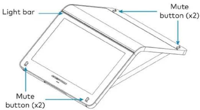
text_image
Light bar Mute button (x2) Mute button (x2)The four mute buttons and the light bar will display red or green to indicate the following states:
• Lighted green: The microphone is unmuted.
• Lighted red: The microphone is muted.
- Flashing green: The device is powering on.
Factory Reset the Device
A factory reset may be performed when troubleshooting the conference device.
To perform a factory reset on the conference device:
- Power cycle the device by disconnecting and reconnecting the CAT5e cable from the conference device.
- When the device powers on and the LEDs flash green, tap the button below the Crestron® logo 10 times. A factory reset confirmation screen appears.

text_image
Tap x10- Tap one of the mute buttons to move the selector on the factory reset confirmation screen to Yes. Tap the button below the Crestron logo to confirm the factory reset.
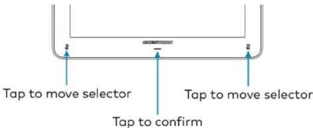
text_image
Tap to move selector Tap to move selector Tap to confirm- The device will reboot. Configure the device according to the Crestron Flex system's Quick Start Guide.
Declaration
NCC警语
NCC Regulatory Information
Support Frequency Bands and Power:
BT< 8 dBm;
WLAN 2412-2462 MHz < 25 dBm;
WLAN 5150-5825 MHz < 18 dBm;
Mounting TS-1070-B-S Tabletop Touch Screen
The TS-1070-B-S Tabletop Touch Screen can be placed on the conference table or any flat surface.
Mounting TSW-1070-B-S Wall Mount Touch Screen
Mount the included touch screen according to the TSW-70 Series Product Manual (Doc. 8550).
Mounting the UC Bracket Assembly
Mount the UC Bracket Assembly to VESA® compliant display devices, a wall, or other building structure. Anchors and screws are supplied for installation on walls with 3/8 in. (9.5 mm) to 3/4 in. (19 mm) thickness.
CAUTION: Preinstalled screws may protrude from the back of the UC Bracket Assembly. Exercise caution when handling the UC Bracket Assembly to avoid scratching or damaging surfaces.
NOTE: The integrated cable tie wraps are reusable. Avoid damaging the cable tie wraps.
Mounting UC-CAM-L1
Mount the camera according to its included documentation.
Mounting CCS-CAM-USB-F-400
Mount the camera using the included UC-CAM-WMK wall mount kit.
The wall mount kit provides secure mounting options for CCS-CAM-USB-F-400. It comes with two mounting brackets and mounting hardware that allow for a variety of mounting locations.
In the Box (UC-CAM-WMK)
| Qty. Description | |
| 1 UC-CAM-WMK, Wall Mount Kit for CCS-CAM-USB-F-400 (6510998) | |
| Additional Items | |
| 2 Anchor, Wall, Plastic, #6 x 1-1/4 in. (2043585) | |
| 1 Bracket, Camera, 2.00 in. to 3.50 in. (51 mm to 89 mm) (2053562) | |
| 1 Bracket, Camera, 3.50 in. to 5.00 in. (89 mm to 127 mm) (2053561) | |
| 1 Screw, 1/4-20, 5/16 in., Flat Head, Phillips (2040253) | |
| 2 Screw, 6-AB x 1 in., Pan Head, Phillips, Black (2053606) | |
| 2 Tie Wrap, Releasable (2005430) | |
Installing the Wall Mount Kit
Select an appropriate mounting location and install the bracket.
Choose a Location
For optimal viewing results, the bracket should be mounted in a location that places the camera above the plane of the room's conference table.
Choose a Bracket
The wall mount kit comes with two brackets to accommodate a variety of mounting locations. The smaller bracket allows the back of the camera to be placed 2.00 in. to 3.50 in. (51 mm to 89 mm) off wall while the larger bracket allows the back of the camera to be placed 3.50 in. to 5.00 in. (89 mm to 127 mm) off the wall.
NOTES:
- The camera can be mounted on top of or under the bracket.
- When using the CCS-CAM-USB-F-100, the smaller bracket allows the back of the camera to be placed 2.25 in. to 3.00 in. (57 mm to 76 mm) off the wall while the larger bracket allows the back of the camera to be placed 3.75 in. to 4.55 in. (95 mm to 116 mm) off the wall.
Small bracket, CCS-CAM-USB-F-400 camera shown

text_image
Camera 3.50 in. (89 mm) 2.00 in. (51 mm) Screw, 6-AB x 1 in., Pan Head (x2) Bracket 3.80 in. (97 mm) 1.50 in. (38 mm) 4.61 in. (117 mm) 6.35 in. (162 mm) USB PortLarge bracket, CCS-CAM-USB-F-400 camera shown

text_image
5.00 in. (127 mm) 3.50 in. (89 mm) Camera Bracket Screw, 6-AB x 1 in., Pan Head (x2) 1.50 in. (38 mm) 3.80 in. (97 mm) 1.30 in. (33 mm) 6.10 in. (155 mm) USB Port 7.85 in. (199 mm)Secure the Bracket
Secure the bracket to the mounting surface with the included 6-AB x 1 in. pan head screws. Use the included anchors for mounting locations where a stud cannot be found.
Secure the bracket (large bracket shown)

text_image
Screw, 6-AB x 1 in., Pan Head (x2) BracketAttach the Camera
Attach the camera to the bracket with the included 1/4-20, 5/16 in. flat head screw. The camera can be positioned forward and back along the bracket.
Attach the camera (large bracket with CCS-CAM-USB-F-400 camera shown)
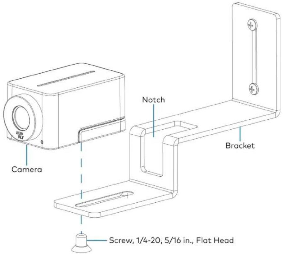
text_image
RUB BLT Camera Notch Bracket Screw, 1/4-20, 5/16 in., Flat HeadConnect
Thread the cable that is included with the camera through the notch in the bracket and connect it to the camera's USB port and a USB device. Use the included tie wraps to secure excess cable.
NOTE: On the CCS-CAM-USB-F-100, the cable is attached to the camera.
Mounting UC-SB1-CAM-FLEX
In the Box
Qty. Description
| 1 UC-SB1-CAM-FLEX, UC Video Conference Smart Soundbar & Camera (6511283) |
| Additional Items |
| 4 Anchor, Drywall, Plastic, 3/8 in. x 1/2 in. (2052565) |
| 1 Cable, USB 3.0, A - B, 6 ft (1.83 m) (2053077) |
| 2 Foot, 2.3 in. x 0.96 in. x 0.15 in., Rubber (2052169) |
| 1 Key, Anchor (4529654) |
| 1 Power Cord, 5 ft 10 in. (1.78 m) (2042043) |
| 1 Power Pack, 24 VDC, 2.5 A, 100-240 VAC (2045873) |
| 4 Screw, 8-AB x 1-1/2 in., Pan Head, Combo (2052567) |
| 1 Template, Overlay (4529513) |
The soundbar can be placed on a flat surface or mounted on a wall. The soundbar has the following dimensions.

text_image
3.90 in. (99 mm) 4.57 in. (116 mm) 43.60 in. (1107 mm)Place on a Flat Surface
If the soundbar is to be placed on a flat surface, attach the included rubber feet to the bottom of the soundbar as shown.
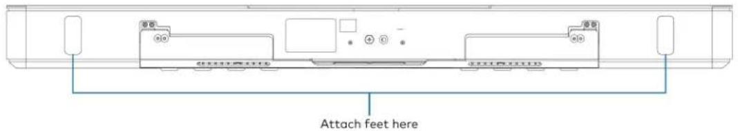
text_image
Attach feet hereMount on a Wall
The soundbar includes anchors that are suitable for mounting it on sheetrock walls up to 1/2 in. (13 mm thickness. Masonry and other materials may require additional installer-supplied mounting hardware.
NOTES:
- For optimal viewing results, the soundbar should be mounted in a location that places the camera approximately 12 in. (305 mm) above the plane of the room's conference table.
- When mounting on a wall beneath a display device, leave 3/4 in. (19 mm) (minimum) clearance above the top of the soundbar. Use the included template to allow for sufficient clearance between the soundbar and display device.
The following tools are required to mount the soundbar:
• Drywall saw (not included)
- Drill with 5/16 in. bit (not included)
A template is included to provide drill hole locations for the included mounting hardware.
- Attach the template to the desired mounting location with the template's center reference line at the center of the desired location.
NOTE: Use the center reference hole of the template as a guide to attach the template.

text_image
Drill one of these two holes Cutout for soundbar cables Center reference hole Drill one of these two holes SOUNDBAR ACTUAL HEIGHT MIN. DISTANCE FROM BOTTOM OF DISPLAY CENTER REFERENCE HOLE TO HOLD TEMPLATE TEMPORALLY TEMPLATE - 40161 FOR UC-SB1 TOTAL OF 4 SCREWS MUST BE USED (2 ON EACH SIDE, 1 PER ROW) TO SECURE THE SOUNDBAR TO THE WALL Drill one of these two holes Center reference line Drill one of these two holes- Drill two pilot holes on each side of the center reference line as shown in the previous diagram. Each side should have one pilot hole drilled in each row of the template.
- Use a drywall saw to make a cutout in the wall for the soundbar cables. The cutout in the center of the template provides adequate access for all of the required cabling.
-
Install the four included anchors and screws into the drilled pilot holes.
-
Place the soundbar face down, and pivot the wall bracket away from the soundbar.

text_image
Wall bracket Soundbar- Place the wall bracket over the screws, and hand tighten the screws until the wall bracket is secured to the wall.
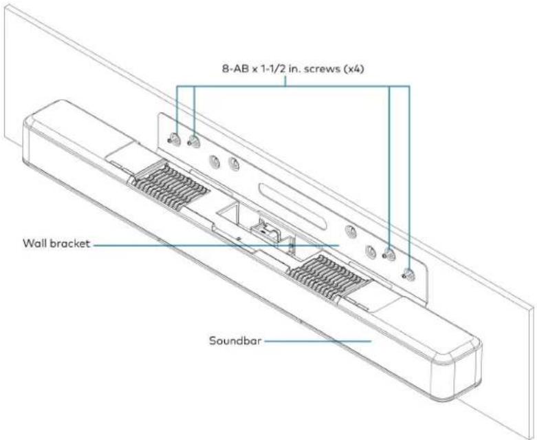
text_image
8-AB x 1-1/2 in. screws (x4) Wall bracket Soundbar- Route the cables through the cable cutout.
NOTE: The included power pack's cord is typically routed from the wall opening, through the cable cutout, to the soundbar.
Connect
Make the necessary connections as called out in the following diagram. Connect power last. Once all connections are made, pivot the soundbar up to the wall bracket until the soundbar locks into place.

text_image
PC Audio and video to UC Engine CAMERA From USB camera (Pre-connected, wiring removed for clarity) 24 V, 2.5 A From included power pack AUDIO IN and OUT Line-level audio input and output- PC: Connect the included USB cable to the PC port and to a USB port on the UC Engine. For optimal results, use a USB 3.0 connection.
• CAMERA: The integrated camera is already connected from the factory.
• 24 V, 2.5 A: Connect the power pack to the 24 V, 2.5 A power input and to an AC power out
- AUDIO IN and AUDIO OUT: The soundbar provides unbalanced, stereo, analog input and output jacks (3.5 mm TRS mini-phone). The AUDIO IN port accommodates an optional line-level audio source which feeds to the internal amplifier and speakers without a volume control or other signal processing. The AUDIO OUT port provides a line-level signal for an optional assistive listening system and carries the same audio signal as the soundbar speakers.
Status and System Control
When used as part of a Crestron Flex system, the soundbar is controlled by the system's touch screen.
The front panel status bar illuminates to provide operational information.
- A green status bar indicates the volume level. Raising the volume increases the status bar's illumination. Lowering the volume decreases the status bar's illumination. When the volume = "0", the status bar is unlit.

natural_image
Front view of a white electronic device with a green horizontal bar and circular button (no visible text or symbols)- Muting the microphone and speaker turns the two outer segments of the status bar red.

natural_image
Top-down view of a sound chamber with sound waves, central speaker grille, and circular button (no text or symbols)- Muting the microphone turns the center of the status bar red.

natural_image
Front view of a modern air conditioner unit with ventilation grilles and a red horizontal stripe (no text or symbols visible)Mounting UC-SB-P50(-INDIA)
Mount the Jabra PanaCast 50 intelligent video bar for Crestron Flex Systems according to its included documentation.
Mounting the UC-PR and Cable Organizer
Mount the UC Presentation Transmitter to the underside of a table using the supplied screws. The supplied screws support installation on tables with a thickness of 1 in. (25.4 mm) minimum.
The included Crestron cable organizer for the UC-PR provides convenient tabletop cable management. The cable organizer routes audio and network connections from the UC-PR to a system's tabletop controller and routes audio and video connections to a user's laptop for Bring Your Own Device (BYOD) presentation.
In the Box (Cable Organizer)
| Qty. Description | |
| 1 Cable Organizer | |
| Additional Items | |
| 1 Cable organizer housing, Plastic, Black (2056826) | |
| 1 Cable organizer plate, Plastic, Black (2056825) | |
| 2 Locking nut, Plastic, Black (2056824) | |
| 2 Screw, 04-40, 3/8 in., Pan Head, Phillips, Black (2007170) | |
| 5 Cable tie wrap, 7.4 in. x 0.19 in., Black (2057355) | |
Installing the Cable Organizer
To install the cable organizer:
- Select a mounting surface with a thickness of 1 in. (25 mm) to 1.5 in. (38 mm).
- Use a hole saw to cut a 2.5 in. (64 mm) wide mounting hole in the mounting surface.
- Insert the cable organizer housing into the mounting hole.
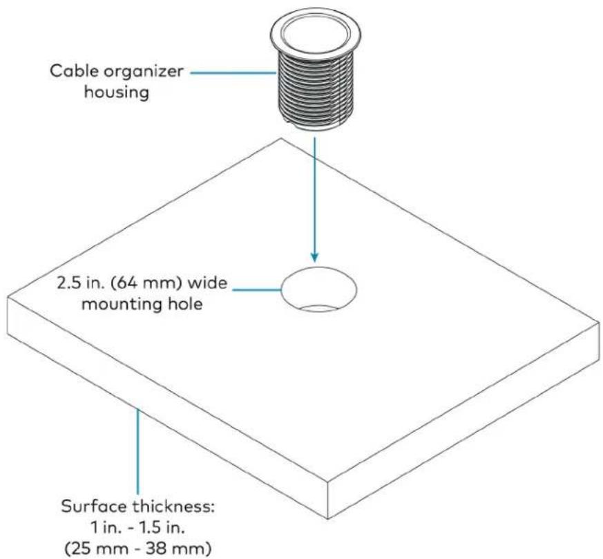
text_image
Cable organizer housing 2.5 in. (64 mm) wide mounting hole Surface thickness: 1 in. - 1.5 in. (25 mm - 38 mm)- Secure the cable organizer housing to the mounting surface using the included locking nuts. Ensure that the TOP label on the locking nuts faces the mounting surface.

text_image
Cable organizer housing Mounting surface Locking nut (x2)-
Pass cables through the bottom of the cable organizer housing to the tabletop.
-
Route the cables through the routing holes on the cable organizer plate. All of the necessary cables are included with the Crestron Flex conference system.
NOTE: The USB B routing hole is only used in systems with a Crestron Flex MM tabletop conference device.
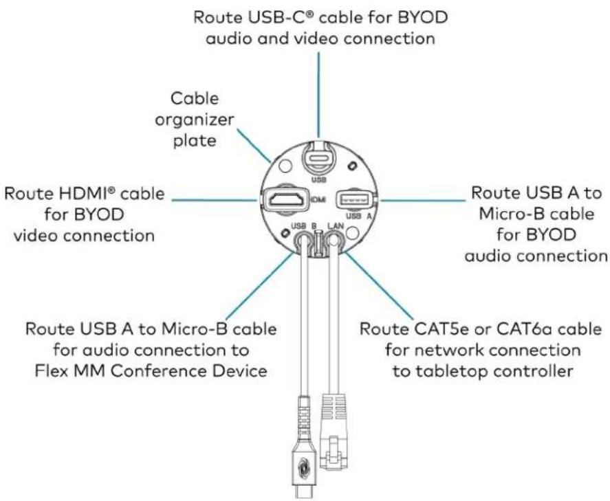
text_image
Route USB-C® cable for BYOD audio and video connection Cable organizer plate Route HDMI® cable for BYOD video connection USB A to Micro-B cable for BYOD audio connection USB B LAN Route USB A to Micro-B cable for audio connection to Flex MM Conference Device Route CAT5e or CAT6a cable for network connection to tabletop controller- Attach the cable organizer plate to the cable organizer housing with the included screws.

text_image
Attach screw USB HDMI USB A USB B LAN Attach screw Cable organizer housing- Above the mounting surface, pull all of the cables out to the needed length. Ensure that there is a least 2 in. (51 mm) of cable slack beneath the mounting surface, and attach a cable tie to each cable. Trim the cable ties as needed and push the cables back to the cable organizer plate.
NOTE: The cable ties prevent overextension by catching on the bottom of the cable organizer plate when the cable is pulled to its maximum length. The added slack ensures that the cables will not disconnect from the UC-PR.
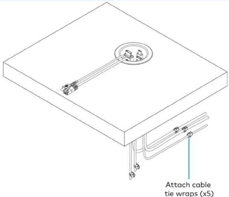
text_image
Attach cable tie wraps (x5)Connect Devices
Connect devices using the cables routed through the cable organizer, as described in the system's Quick Start guide. Scan or click one of the following QR codes to view the system's Quick Start guide.
Mounting CCS-UCA-MIC
The CCS-UCA-MIC extension microphone pod can be placed on the conference table or any flat surface.
Connections
This section provides the following information:
UC-B30-T and UC-B30-T-WM Connections
Minimum Requirements
Ensure that the below requirements are met prior to setting up the system.
- A video display (not included) connected to the UC Engine. A second display is optional.
- A Microsoft Teams Rooms provisioned account (not included).
NOTE: Unless otherwise indicated in this section, the connection procedure is the same for UC-B30-T and UC-B30-T-WM.
Identify the UC Bracket Assembly
The UC Bracket Assembly is available in two models. Identify the model included with your Crestron Flex system. Tap or click the corresponding image below to navigate to the appropriate connection instructions.
UC Bracket Assembly with HD-CONV-USB-200 UC Bracket Assembly with HD-CONV-USB-300

natural_image
Technical line drawing of an electrical enclosure with wiring and connectors (no text or symbols)
text_image
Technical schematic diagram of a device with labeled components and wiring, including a rectangular panel and a multi-panel device with Chinese text labels.System Overview
For UC Bracket Assembly with HD-CONV-USB-200
When connections are complete, the system appears as shown below. Refer to Make Connections on page 127 for detailed connection instructions.
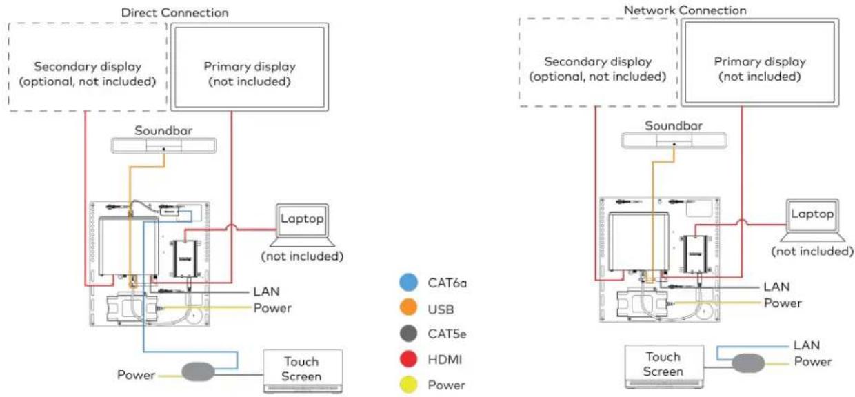
flowchart
graph TD
    subgraph Direct Connection
        A["Secondary display (optional, not included)"]
        B["Primary display (not included)"]
        C["Soundbar"]
        D["Laptop (not included)"]
        E["Touch Screen"]
        F["LAN Power"]
    end

    subgraph Network Connection
        G["Secondary display (optional, not included)"]
        H["Primary display (not included)"]
        I["Soundbar"]
        J["Laptop (not included)"]
        K["Touch Screen"]
        L["LAN Power"]
    end

    A --> C
    B --> D
    C --> E
    D --> F
    E --> G
    F --> H
    G --> I
    H --> J
    I --> K
    style A fill:#f9f,stroke:#333
    style B fill:#f9f,stroke:#333
    style C fill:#ccf,stroke:#333
    style D fill:#cfc,stroke:#333
    style E fill:#fcc,stroke:#333
    style F fill:#cff,stroke:#333
    style G fill:#ffc,stroke:#333
    style H fill:#ffc,stroke:#333
    style I fill:#ffc,stroke:#333
    style J fill:#ffc,stroke:#333
    style K fill:#ffc,stroke:#333
    style L fill:#cfc,stroke:#333
For UC Bracket Assembly with HD-CONV-USB-300
When connections are complete, the system appears as shown below. Refer to Make Connections on page 127 for detailed connection instructions.

flowchart
graph TD
    subgraph Direct Connection
        A["Secondary display (optional, not included)"]
        B["Primary display (not included)"]
        C["Soundbar"]
        D["Laptop (not included)"]
        E["Touch Screen"]
        F["LAN Power"]
    end

    subgraph Network Connection
        G["Secondary display (optional, not included)"]
        H["Primary display (not included)"]
        I["Soundbar"]
        J["Laptop (not included)"]
        K["Touch Screen"]
        L["LAN Power"]
    end

    A --> C
    B --> D
    C --> E
    D --> F
    E --> G
    F --> H
    G --> I
    H --> J
    I --> K
    style A fill:#f9f,stroke:#333
    style B fill:#f9f,stroke:#333
    style C fill:#ccf,stroke:#333
    style D fill:#cfc,stroke:#333
    style E fill:#fcc,stroke:#333
    style F fill:#cff,stroke:#333
    style G fill:#ffc,stroke:#333
    style H fill:#ffc,stroke:#333
    style I fill:#ffc,stroke:#333
    style J fill:#cfc,stroke:#333
    style K fill:#cfc,stroke:#333
    style L fill:#fcc,stroke:#333
NOTE: For reference, the UC Bracket Assembly is shown with the HD-CONV-USB-200 in the following connection diagrams. Unless otherwise indicated in this guide, the connections remain the same for the UC Bracket Assembly with HD-CONV-USB-200 and HD-CONV-USB-300.
- Make UC Engine connections as shown in the following illustrations. The touch screen can communicate with the UC Engine over a direct connection or a network connection. Select one of the connection types as described below.
- Make a direct connection for simple installation and setup. Only use the direct connect adapter to connect the touch screen's PoE injector to the UC Engine. Do not use the direct connect adapter to connect the UC Engine to the network.
Direct Connection

flowchart
graph TD
    A["UC Engine"] --> B["Tabletop Touch Screen"]
    B --> C["Wall mount Touch Screen"]
    D["PoE Injector"] --> E["Direct connect adapter"]
    E --> B
    F["Preconnected"] --> G["BAT5e 7 ft (2.1 m) CAT5e cable (x2)"]
    F --> H["BAT6a 20 ft (6.1 m) CAT6a patch cable"]
    F --> I["Power PoE Injector UC Bracket Assembly"]
    J["LAN"] --> K["Data Port"]
    style A fill:#f9f,stroke:#333
    style B fill:#ccf,stroke:#333
    style C fill:#cfc,stroke:#333
    style D fill:#fcc,stroke:#333
    style E fill:#ffc,stroke:#333
    style F fill:#cff,stroke:#333
    style G fill:#ffc,stroke:#333
    style H fill:#ffc,stroke:#333
    style I fill:#ffc,stroke:#333
    style J fill:#fcc,stroke:#333
- Make a network connection if the system is to be managed by the XiO Cloud® service.
NOTE: When a network connection is used, disconnect the direct connect adapter from the UC Engine.
Network Connection
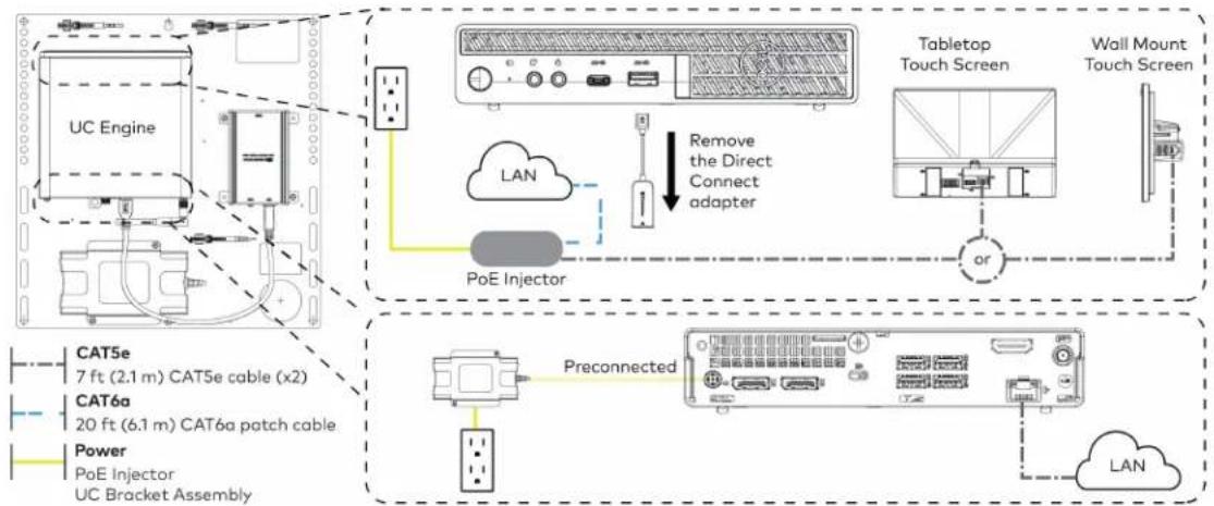
flowchart
graph TD
    A["UC Engine"] --> B["PoE Injector"]
    B --> C["Tabletop Touch Screen"]
    C --> D["Wall Mount Touch Screen"]
    D --> E["Preconnected"]
    E --> F["Power PoE Injector"]
    F --> G["CAT5e 7 ft (2.1 m) CAT5e cable (x2)"]
    F --> H["CAT6a 20 ft (6.1 m) CAT6a patch cable"]
    F --> I["LAN"]
    B --> J["Remove the Direct Connect adapter"]
    J --> K["LAN"]
    style A fill:#f9f,stroke:#333
    style B fill:#ccf,stroke:#333
    style C fill:#cfc,stroke:#333
    style D fill:#fcc,stroke:#333
    style E fill:#cff,stroke:#333
    style F fill:#ffc,stroke:#333
    style G fill:#cfc,stroke:#333
    style H fill:#fcc,stroke:#333
    style I fill:#ffc,stroke:#333
- Connect displays to the UC Engine.

text_image
UC Engine HDMI Primary: 6 ft (1.8 m) HDMI cable Secondary: 6 ft (1.8 m) DisplayPort to HDMI cable Secondary display (optional, not included) Primary display (not included)- Connect the soundbar to the UC Engine as shown in the image below. Do not connect the soundbar to any of the other USB ports.

text_image
UC Engine Power supply Soundbar HD-CONV-USB-200 or HD-CONV-USB-300 (preconnected) USB 6 ft (1.8 m) USB 3.0, A-B Power Power supply- Connect a laptop to the HD-CONV-USB-200 or HD-CONV-USB-300.
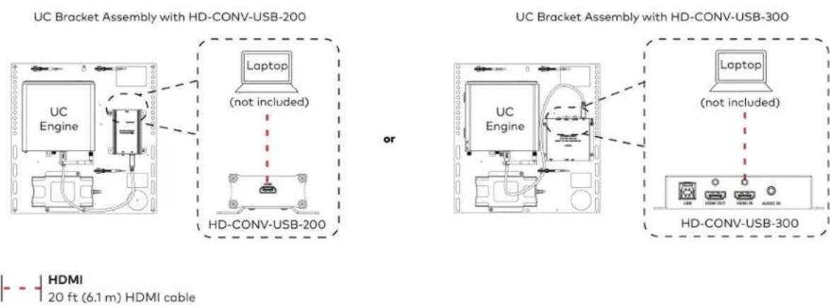
text_image
UC Bracket Assembly with HD-CONV-USB-200 Laptop (not included) or UC Bracket Assembly with HD-CONV-USB-300 UC Engine UC Engine (not included) Laptop (HDMI 20 ft (6.1 m) HDMI cable) HD-CONV-USB-300 HDMI 20 ft (6.1 m) HDMI cable- Bundle the cables to the bracket assembly with the integrated cable tie wraps. The cable tie wraps are reusable.
Apply Power
Press the power button on the bottom of the UC Engine and apply power to all of the other devices in the system.
Configure the Touch Screen
NOTE: If a direct connection was made during installation, skip to Configure the System on page 129.
- On a computer, enter the IP address of the touch screen into a web browser. Log in and navigate to Settings > Applications.
NOTES:
- The touch screen (via the PoE injector) and computer must be on the same network switch and VLAN.
-
A login with administrative rights for the touch screen is required.
-
Enter the following information in the appropriate fields:
- Teams Video PC Address: Enter the IP address or hostname of the UC Engine.
NOTE: The hostname is printed on a label affixed to the UC Engine (mounted on the UC bracket assembly).
- Teams Video PC Port: By default, port number 49500 is used. If a different port number h been configured on the UC Engine, enter that port number instead.
- Teams Video Username: Enter the login username for the UC Engine. (The default username is "admin".)
-
Teams Video Password: Enter the login password for the UC Engine. (The default password is "sfb".)
-
Select Save Changes.
Configure the System
Use the touch screen and your Microsoft Teams credentials to configure the UC Engine, as described in Configuration on page 222. For detailed information on deploying Microsoft Teams Rooms, refer to the Microsoft Teams Rooms documentation.
UC-BX30-T and UC-BX30-T-WM Connections
Minimum Requirements
Ensure that the below requirements are met prior to setting up the system.
- A video display (not included) connected to the UC Engine. A second display is optional.
• A Microsoft Teams Rooms provisioned account (not included).
NOTE: Unless otherwise indicated in this section, the connection procedure is the same for UC-BX30-T and UC-BX30-T-WM.
System Overview
When connections are complete, the system appears as shown below. The laptop connections shown below may vary based on the selected connection method. Refer to Make Connections on page 131 for detailed connection instructions.
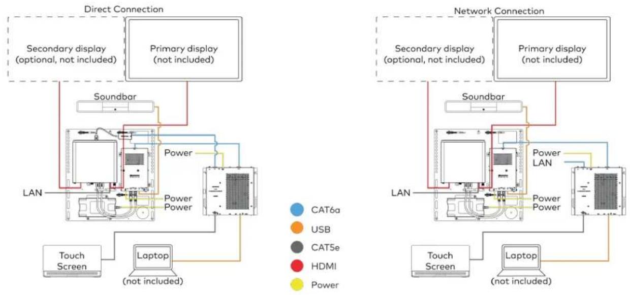
Make Connections
- Make UC Engine connections as shown in the following illustrations. The UC Presentation Transmitter can communicate with the UC Engine over a direct connection or a network connection. Select one of the connection types as described below.
- Make a direct connection for simple installation and setup. Only use the direct connect adapter to connect the UC Presentation Transmitter to the UC Engine. Do not use the direct connect adapter to connect the UC Engine to the network.
Direct Connection

flowchart
graph TD
    A["UC Engine"] --> B["Direct connect adapter"]
    B --> C["UC Presentation Transmitter"]
    D["Preconnected"] --> E["Secondary display (optional, not included)"]
    D --> F["Primary display (not included)"]
    G["TCAT5e 7 ft (2.1 m) CAT5e cable"] --> H["HDMI Primary: 6 ft (1.8 m) HDMI cable"]
    I["TCAT6a 20 ft (6.1 m) CAT6a patch cable"] --> H
    J["TCAT6b Primary: 6 ft (1.8 m) DisplayPort to HDMI cable"] --> H
    K["TCAT6c Primary: 6 ft (1.8 m) HDMI cable"] --> H
    L["TCAT6d Primary: 6 ft (1.8 m) DisplayPort to HDMI cable"] --> H
    M["TCAT6e Primary: 6 ft (2.1 m) CAT6e cable"] --> N["HDMI Primary: 6 ft (1.8 m) HDMI cable"]
    O["TCAT6f Primary: 6 ft (2.1 m) CAT6f patch cable"] --> N
    P["TCAT6g Primary: 6 ft (1.8 m) HDMI cable"] --> N
    Q["TCAT6h Primary: 6 ft (1.8 m) HDMI cable"] --> R["HDMI Primary: 6 ft (1.8 m) HDMI cable"]
    S["TCAT6i Primary: 6 ft (1.8 m) HDMI cable"] --> T["HDMI Primary: 6 ft (1.8 m) HDMI cable"]
    U["TCAT6j Primary: 6 ft (1.8 m) HDMI cable"] --> V["HDMI Primary: 6 ft (1.8 m) HDMI cable"]
    W["TCAT6k Primary: 6 ft (1.8 m) HDMI cable"] --> X["HDMI Primary: 6 ft (1.8 m) HDMI cable"]
    Y["TCAT6l Primary: 6 ft (1.8 m) HDMI cable"] --> Z["HDMI Primary: 6 ft (1.8 m) HDMI cable"]
    AA["TCAT6m Primary: 6 ft (1.8 m) HDMI cable"] --> AB["HDMI Primary: 6 ft (1.8 m) HDMI cable"]
    AC["TCAT6n Primary: 6 ft (1.8 m) HDMI cable"] --> AD["HDMI Primary: 6 ft (1.8 m) HDMI cable"]
    AE["TCAT6o Primary: 6 ft (1.8 m) HDMI cable"] --> AF["HDMI Primary: 6 ft (1.8 m) HDMI cable"]
    AG["TCAT6p Primary: 6 ft (1.8 m) HDMI cable"] --> AH["HDMI Primary: 6 ft (1.8 m) HDMI cable"]
    AI["TCAT6q Primary: 6 ft (1.8 m) HDMI cable"] --> AJ["HDMI Primary: 6 ft (1.8 m) HDMI cable"]
    AK["TCAT6r Primary: 6 ft (1.8 m) HDMI cable"] --> AL["HDMI Primary: 6 ft (1.8 m) HDMI cable"]
    AM["TCAT6g Primary: 6 ft (1.8 m) HDMI cable"] --> AN["HDMI Primary: 6 ft (1.8 m) HDMI cable"]
- Make a network connection if the system is to be managed by the XiO Cloud® service.
NOTE: When a network connection is used, disconnect the direct connect adapter from the UC Engine.
Network Connection

flowchart
graph TD
    A["UC Engine"] -->|Preconnected| B["Preconnected"]
    B --> C["Secondary display (optional, not included)"]
    B --> D["Primary display (not included)"]
    C --> E["LAN"]
    D --> E
    F["CAT5e 7 ft (2.1 m) CAT5e cable"] --> A
    G["HDMI Primary: 6 ft (1.8 m) HDMI cable"] --> A
    H["Secondary: 6 ft (1.8 m) DisplayPort to HDMI cable"] --> A
    I["Power UC Bracket Assembly"] --> A
    J["Remove the Direct Connect adapter"] --> K["Device with ports and indicator"]
- Connect the power supply and the soundbar to the bottom of the content ingest device (HD-CONV-USB-260). Connect the power supplies to an AC power outlet.

text_image
UC Engine CAMERA (USB 3.0, B) CAM (USB 3.0, A) AUX (USB 2.0, A) CONTENT (USB 3.0, B) 24V 1.25A (Barrel jack) Preconnected to UC Engine HD-CONV-USB-260 Power supply Soundbar Power supply Power Power Supply (x2) USB 6 ft (1.8 m) USB 3.0, A - B- Connect power and the content ingest device (HD-CONV-USB-260) to the top of the UC Presentation Transmitter. Connect the UC Engine or LAN to make a direct or network connection as described in step 1.
NOTE: If a longer cable between the UC Presentation Transmitter and the HD-CONV-USB-260 is needed, use a DigitalMedia™ Ultra cable only. The maximum supported cable length is 300 ft (91.4 m).

text_image
CAT6a 20 ft (6.1 m) CAT6a patch cable (x2) Power UC Presentation Transmitter LAN (network connection) or UC Engine (direct connection) UC Presentation Transmitter To RT 34V/1000 8.0A PWM LAN G HD-CONV-USB-260- Connect the touch screen to the bottom of the UC Presentation Transmitter.
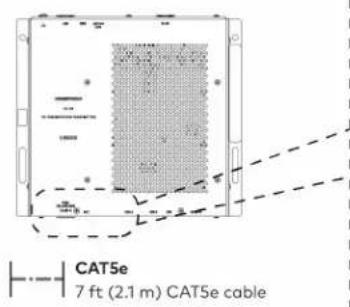
text_image
CAT5e 7 ft (2.1 m) CAT5e cable
text_image
For firmware loading For UC-MMX30 systems only UC Presentation Transmitter Polo+ F2E 30W MAX ACC USB A or Wall Mount Touch Screen Tabletop Touch screen- Connect a laptop to either the USB port or both the HDMI and USB B ports on the bottom of the UC Presentation Transmitter. Select a connection type based on the available ports on the user's laptop.
NOTE: If the USB port is used along with either the HDMI or USB B port, the UC Presentation Transmitter will communicate via the USB port by default.

text_image
UC Presentation Transmitter or Laptop (not included) UC Presentation Transmitter Laptop (not included) HDMI 6.56 ft (2 m) HDMI cable (for BYOD functionality) USB 6.56 ft (2 m) USB A - Micro B cable 6.56 ft (2 m) USB cable (both for BYOD functionality)- Bundle the cables to the bracket assembly with the integrated cable tie wraps. The cable tie wraps are reusable.
Apply Power
Press the power button on the bottom of the UC Engine and apply power to all of the other devices in the system.
NOTE: If a direct connection was made during installation, skip to Configure the System on page 134.
- On a computer, enter the IP address of the touch screen into a web browser. Log in and navigate to Settings > Applications.
NOTES:
- The touch screen (via the PoE injector) and computer must be on the same network switch and VLAN.
-
A login with administrative rights for the touch screen is required.
-
Enter the following information in the appropriate fields:
- Teams Video PC Address: Enter the IP address or hostname of the UC Engine.
NOTE: The hostname is printed on a label affixed to the UC Engine (mounted on the UC bracket assembly).
- Teams Video PC Port: By default, port number 49500 is used. If a different port number h been configured on the UC Engine, enter that port number instead.
- Teams Video Username: Enter the login username for the UC Engine. (The default username is "admin".)
-
Teams Video Password: Enter the login password for the UC Engine. (The default password is "sfb".)
-
Select Save Changes.
Configure the System
Use the touch screen and your Microsoft Teams credentials to configure the UC Engine, as described in Configuration on page 222. For detailed information on deploying Microsoft Teams Rooms, refer to the Microsoft Teams Rooms documentation.
UC-B31-T and UC-B31-T-WM Connections
Minimum Requirements
Ensure that the below requirements are met prior to setting up the system.
- A video display (not included) connected to the UC Engine. A second display is optional.
• A Microsoft Teams Rooms provisioned account (not included).
NOTE: Unless otherwise indicated in this section, the connection procedure is the same for UC-B31-T and UC-B31-T-WM.
Identify the UC Bracket Assembly
The UC Bracket Assembly is available in two models. Identify the model included with your Crestron Flex system. Tap or click the corresponding image below to navigate to the appropriate connection instructions.
UC Bracket Assembly with HD-CONV-USB-200 UC Bracket Assembly with HD-CONV-USB-300
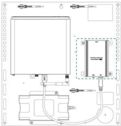
natural_image
Technical line drawing of a mechanical or electrical assembly with no visible text, numbers, or symbols.
text_image
Technical schematic diagram of a device with labeled components and wiring connectionsSystem Overview
For UC Bracket Assembly with HD-CONV-USB-200
When connections are complete, the system appears as shown below. Refer to Make Connections on page 137 for detailed connection instructions.
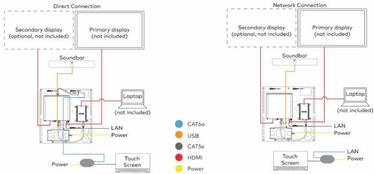
flowchart
graph TD
    subgraph Direct Connection
        A["Secondary display (optional, not included)"]
        B["Primary display (not included)"]
        C["Soundbar"]
        D["Laptop (not included)"]
        E["Touch Screen"]
        F["LAN Power"]
    end

    subgraph Network Connection
        G["Secondary display (optional, not included)"]
        H["Primary display (not included)"]
        I["Soundbar"]
        J["Laptop (not included)"]
        K["Touch Screen"]
        L["LAN Power"]
    end

    A --> C
    B --> D
    C --> E
    D --> F
    E --> G
    F --> H
    G --> I
    H --> J
    I --> K
    style A fill:#f9f,stroke:#333
    style B fill:#f9f,stroke:#333
    style C fill:#ccf,stroke:#333
    style D fill:#ccf,stroke:#333
    style E fill:#ccf,stroke:#333
    style F fill:#ccf,stroke:#333
    style G fill:#cfc,stroke:#333
    style H fill:#cfc,stroke:#333
    style I fill:#cfc,stroke:#333
    style J fill:#cfc,stroke:#333
    style K fill:#cfc,stroke:#333
    style L fill:#fcc,stroke:#333
For UC Bracket Assembly with HD-CONV-USB-300
When connections are complete, the system appears as shown below. Refer to Make Connections on page 137 for detailed connection instructions.
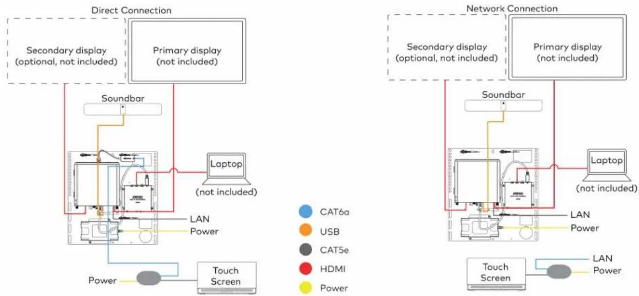
flowchart
graph TD
    subgraph Direct Connection
        A["Secondary display (optional, not included)"]
        B["Primary display (not included)"]
        C["Soundbar"]
        D["Laptop (not included)"]
        E["Touch Screen"]
        F["LAN Power"]
    end

    subgraph Network Connection
        G["Secondary display (optional, not included)"]
        H["Primary display (not included)"]
        I["Soundbar"]
        J["Laptop (not included)"]
        K["Touch Screen"]
        L["LAN Power"]
    end

    A --> C
    B --> D
    C --> E
    D --> F
    E --> G
    F --> H
    G --> I
    H --> J
    I --> K
    style A fill:#f9f,stroke:#333
    style B fill:#f9f,stroke:#333
    style C fill:#ccf,stroke:#333
    style D fill:#cfc,stroke:#333
    style E fill:#fcc,stroke:#333
    style F fill:#cff,stroke:#333
    style G fill:#ffc,stroke:#333
    style H fill:#ffc,stroke:#333
    style I fill:#ffc,stroke:#333
    style J fill:#cfc,stroke:#333
    style K fill:#cfc,stroke:#333
    style L fill:#fcc,stroke:#333
NOTE: For reference, the UC Bracket Assembly is shown with the HD-CONV-USB-200 in the following connection diagrams. Unless otherwise indicated in this guide, the connections remain the same for the UC Bracket Assembly with HD-CONV-USB-200 and HD-CONV-USB-300.
- Make UC Engine connections as shown in the following illustrations. The touch screen can communicate with the UC Engine over a direct connection or a network connection. Select one of the connection types as described below.
- Make a direct connection for simple installation and setup. Only use the direct connect adapter to connect the touch screen's PoE injector to the UC Engine. Do not use the direct connect adapter to connect the UC Engine to the network.
Direct Connection

flowchart
graph TD
    A["UC Engine"] --> B["Tabletop Touch Screen"]
    B --> C["Wall mount Touch Screen"]
    D["PoE Injector"] --> E["Direct connect adapter"]
    E --> B
    F["Preconnected"] --> G["BAT5e 7 ft (2.1 m) CAT5e cable (x2)"]
    F --> H["BAT6a 20 ft (6.1 m) CAT6a patch cable"]
    F --> I["Power PoE Injector UC Bracket Assembly"]
    J["LAN"] --> K["Data Port"]
    style A fill:#f9f,stroke:#333
    style B fill:#ccf,stroke:#333
    style C fill:#cfc,stroke:#333
    style D fill:#fcc,stroke:#333
    style E fill:#ffc,stroke:#333
    style F fill:#cff,stroke:#333
    style G fill:#ffc,stroke:#333
    style H fill:#ffc,stroke:#333
    style I fill:#ffc,stroke:#333
    style J fill:#fcc,stroke:#333
- Make a network connection if the system is to be managed by the XiO Cloud® service.
NOTE: When a network connection is used, disconnect the direct connect adapter from the UC Engine.
Network Connection

flowchart
graph TD
    A["UC Engine"] --> B["PoE Injector"]
    B --> C["Tabletop Touch Screen"]
    C --> D["Wall Mount Touch Screen"]
    D --> E["Preconnected"]
    E --> F["Power PoE Injector"]
    F --> G["CAT5e 7 ft (2.1 m) CAT5e cable (x2)"]
    F --> H["CAT6a 20 ft (6.1 m) CAT6a patch cable"]
    F --> I["LAN"]
    B --> J["Remove the Direct Connect adapter"]
    J --> K["LAN"]
    style A fill:#f9f,stroke:#333
    style B fill:#ccf,stroke:#333
    style C fill:#cfc,stroke:#333
    style D fill:#fcc,stroke:#333
    style E fill:#cff,stroke:#333
    style F fill:#ffc,stroke:#333
    style G fill:#cfc,stroke:#333
    style H fill:#fcc,stroke:#333
    style I fill:#ffc,stroke:#333
- Connect displays to the UC Engine.

text_image
UC Engine HDMI Primary: 6 ft (1.8 m) HDMI cable Secondary: 6 ft (1.8 m) DisplayPort to HDMI cable Secondary display (optional, not included) Primary display (not included)- Connect the soundbar to the UC Engine as shown in the image below. Do not connect the soundbar to any of the other USB ports.

text_image
UC Engine Power supply Power supply Soundbar HD-CONV-USB-200 or HD-CONV-USB-300 (preconnected) USB UC Engine to Soundbar Power Power supply- Connect a laptop to the HD-CONV-USB-200 or HD-CONV-USB-300.
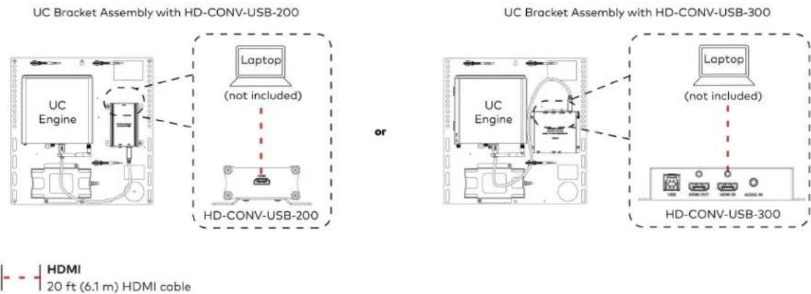
text_image
UC Bracket Assembly with HD-CONV-USB-200 Laptop (not included) or UC Bracket Assembly with HD-CONV-USB-300 UC Engine Laptop (not included) HD-CONV-USB-300 HDMI 20 ft (6.1 m) HDMI cable- Bundle the cables to the bracket assembly with the integrated cable tie wraps. The cable tie wraps are reusable.
Apply Power
Press the power button on the bottom of the UC Engine and apply power to all of the other devices in the system.
Configure the Touch Screen
NOTE: If a direct connection was made during installation, skip to Configure the System on page 139.
- On a computer, enter the IP address of the touch screen into a web browser. Log in and navigate to Settings > Applications.
NOTES:
- The touch screen (via the PoE injector) and computer must be on the same network switch and VLAN.
-
A login with administrative rights for the touch screen is required.
-
Enter the following information in the appropriate fields:
- Teams Video PC Address: Enter the IP address or hostname of the UC Engine.
NOTE: The hostname is printed on a label affixed to the UC Engine (mounted on the UC bracket assembly).
- Teams Video PC Port: By default, port number 49500 is used. If a different port number h been configured on the UC Engine, enter that port number instead.
- Teams Video Username: Enter the login username for the UC Engine. (The default username is "admin".)
-
Teams Video Password: Enter the login password for the UC Engine. (The default password is "sfb".)
-
Select Save Changes.
Configure the System
Use the touch screen and your Microsoft Teams credentials to configure the UC Engine, as described in Configuration on page 222. For detailed information on deploying Microsoft Teams Rooms, refer to the Microsoft Teams Rooms documentation.
UC-BX31-T and UC-BX31-T-WM Connections
Minimum Requirements
Ensure that the below requirements are met prior to setting up the system.
- A video display (not included) connected to the UC Engine. A second display is optional.
• A Microsoft Teams Rooms provisioned account (not included).
NOTE: Unless otherwise indicated in this section, the connection procedure is the same for UC-BX31-T and UC-BX31-T-WM.
System Overview
When connections are complete, the system appears as shown below. The laptop connections shown below may vary based on the selected connection method. Refer to Make Connections on page 141 for detailed connection instructions.

flowchart
graph TD
    subgraph Direct Connection
        A["Secondary display (optional, not included)"]
        B["Primary display (not included)"]
        C["Soundbar"]
        D["Laptop (not included)"]
        E["Touch Screen"]
        F["Power"]
    end

    subgraph Network Connection
        G["Secondary display (optional, not included)"]
        H["Primary display (not included)"]
        I["Soundbar"]
        J["Laptop (not included)"]
        K["Touch Screen"]
        L["Power LAN"]
        M["Power Power"]
    end

    A --> C
    B --> D
    C --> E
    D --> F
    E --> G
    F --> H
    G --> I
    H --> J
    I --> K
    J --> L
    K --> M
Make Connections
- Make UC Engine connections as shown in the following illustrations. The UC Presentation Transmitter can communicate with the UC Engine over a direct connection or a network connection. Select one of the connection types as described below.
- Make a direct connection for simple installation and setup. Only use the direct connect adapter to connect the UC Presentation Transmitter to the UC Engine. Do not use the direct connect adapter to connect the UC Engine to the network.
Direct Connection

flowchart
graph TD
    A["UC Engine"] --> B["Direct connect adapter"]
    B --> C["UC Presentation Transmitter"]
    D["Preconnected"] --> E["Secondary display (optional, not included)"]
    D --> F["Primary display (not included)"]
    G["TCAT5e 7 ft (2.1 m) CAT5e cable"] --> H["HDMI Primary: 6 ft (1.8 m) HDMI cable"]
    I["TCAT6a 20 ft (6.1 m) CAT6a patch cable"] --> H
    J["TCAT6b Primary: 6 ft (1.8 m) DisplayPort to HDMI cable"] --> H
    K["TCAT6c Primary: 6 ft (1.8 m) HDMI cable"] --> H
    L["TCAT6d Primary: 6 ft (1.8 m) DisplayPort to HDMI cable"] --> H
    M["TCAT6e Primary: 6 ft (2.1 m) CAT6e cable"] --> N["HDMI Primary: 6 ft (1.8 m) HDMI cable"]
    O["TCAT6f Primary: 6 ft (2.1 m) CAT6f patch cable"] --> N
    P["TCAT6g Primary: 6 ft (1.8 m) HDMI cable"] --> N
    Q["TCAT6h Primary: 6 ft (1.8 m) HDMI cable"] --> N
    R["TCAT6i Primary: 6 ft (1.8 m) HDMI cable"] --> N
    S["TCAT6j Primary: 6 ft (1.8 m) HDMI cable"] --> N
    T["TCAT6k Primary: 6 ft (1.8 m) HDMI cable"] --> N
    U["TCAT6l Primary: 6 ft (1.8 m) HDMI cable"] --> N
    V["TCAT6m Primary: 6 ft (1.8 m) HDMI cable"] --> N
    W["TCAT6n Primary: 6 ft (1.8 m) HDMI cable"] --> N
    X["TCAT6o Primary: 6 ft (1.8 m) HDMI cable"] --> N
    Y["TCAT6p Primary: 6 ft (1.8 m) HDMI cable"] --> N
    Z["TCAT6q Primary: 6 ft (1.8 m) HDMI cable"] --> N
    AA["TCAT6r Primary: 6 ft (1.8 m) HDMI cable"] --> N
    AB["TCAT6s Primary: 6 ft (1.8 m) HDMI cable"] --> N
    AC["TCAT6t Primary: 6 ft (1.8 m) HDMI cable"] --> N
    AD["TCAT6u Primary: 6 ft (1.8 m) HDMI cable"] --> N
    AE["TCAT6v Primary: 6 ft (1.8 m) HDMI cable"] --> N
    AF["TCAT6w Primary: 6 ft (1.8 m) HDMI cable"] --> N
    AG["TCAT6x Primary: 6 ft (1.8 m) HDMI cable"] --> N
    AH["TCAT6y Primary: 6 ft (1.8 m) HDMI cable"] --> N
    AI["TCAT6z Primary: 6 ft (1.8 m) HDMI cable"] --> N
    AJ["TCAT6w Primary: 6 ft (1.8 m) HDMI cable"] --> N
    AK["TCAT6w Primary: 6 ft (1.8 m) HDMI cable"] --> N
    AL["TCAT6w Primary: 6 ft (1.8 m) HDMI cable"] --> N
    AM["TCAT6w Primary: 6 ft (1.8 m) HDMI cable"] --> N
    AN["TCAT6w Primary: 6 ft (1.8 m) HDMI cable"] --> N
    AO["TCAT6w Primary: 6 ft (1.8 m) HDMI cable"] --> N
    AP["TCAT6w Primary: 6 ft (1.8 m) HDMI cable"] --> N
    AQ["TCAT6w Primary: 6 ft (1.8 m) HDMI cable"] --> N
    AR["TCAT6w Primary: 6 ft (1.8 m) HDMI cable"] --> N
    AS["TCAT6w Primary: 6 ft (1.8 m) HDMI cable"] --> N
    AT["TCAT6w Primary: 6 ft (1.8 m) HDMI cable"] --> N
    AU["TCAT6w Primary: 6 ft (1.8 m) HDMI cable"] --> N
    AV["TCAT6w Primary: 6 ft (1.8 m) HDMI cable"] --> N
    AW["TCAT6w Primary: 6 ft (1.8 m) HDMI cable"] --> N
    AX["TCAT6w Primary: 6 ft (1.8 m) HDMI cable"] --> N
    AY["TCAT5e Primary: 7 ft (2.1 m) CAT5e cable"] --> AZ["HDMI Primary: 20 ft (6.1 m) CAT5e patch cable"]
    BA["TCAT5e Primary: 20 ft (6.1 m) CAT5e patch cable"] --> BB["HDMI Primary: 20 ft (2.1 m) CAT5e cable"]
    BC["TCAT5e Primary: 20 ft (2.1 m) CAT5e patch cable"] --> BD["HDMI Primary: 20 ft (2.1 m) CAT5e cable"]
    BE["TCAT5e Primary: 20 ft (2.1 m) CAT5e patch cable"] --> BF["HDMI Primary: 20 ft (2.1 m) CAT5e cable"]
    BG["TCAT5e Primary: 20 ft (2.1 m) CAT5e patch cable"] --> BH["HDMI Primary: 20 ft (2.1 m) CAT5e cable"]
    BI["TCAT5e Primary: 20 ft (2.1 m) CAT5e patch cable"] --> BJ["HDMI Primary: 20 ft (2.1 m) CAT5e cable"]
    BK["TCAT5e Primary: 20 ft (2.1 m) CAT5e patch cable"] --> BL["HDMI Primary: 20 ft (2.1 m) CAT5e cable"]
    BM["TCAT5e Primary: 20 ft (2.1 m) CAT5e patch cable"] --> BN["HDMI Primary: 20 ft (2.1 m) CAT5e cable"]
    BO["TCAT5e Primary: 20 ft (2.1 m) CAT5e patch cable"] --> BP["HDMI Primary: 20 ft (2.1 m) CAT5e cable"]
    BQ["TCAT5e Primary: 20 ft (2.1 m) CAT5e patch cable"] --> BR["HDMI Primary: 20 ft (2.1 m) CAT5e cable"]
    BS["TCAT5e Primary: 20 ft (2.1 m) CAT5e patch cable"] --> BT["HDMI Primary: 20 ft (2.1 m) CAT5e cable"]
    BU["TCAT5e Primary: 20 ft (2.1 m) CAT5e patch cable"] --> BV["HDMI Primary: 20 ft (2.1 m) CAT5e cable"]
    BW["TCAT5e Primary: 20 ft (2.1 m) CAT5e patch cable"] --> BX["HDMI Primary: 20 ft (2.1 m) CAT5e cable"]
    BY["TCAT5e Primary: 20 ft (2.1 m) CAT5e patch cable"] --> BZ["HDMI Primary: 20 ft (2.1 m) CAT5e cable"]
    CA["TCAT5e Primary: 20 ft (2.1 m) CAT5e patch cable"] --> CB["HDMI Primary: 20 ft (2.1 m) CAT5e cable"]
    CC["TCAT5e Primary: 20 ft (2.1 m) CAT5e patch cable"] --> CD["HDMI Primary: 20 ft (2.1 m) CAT5e cable"]
    CE["TCAT5e Primary: 20 ft (2.1 m) CAT5e patch cable"] --> CF["HDMI Primary: 20 ft (2.1 m) CAT5e cable"]
    CG["TCAT5e Primary: 20 ft (2.1 m) CAT5e patch cable"] --> DH["HDMI Primary: 20 ft (2.1 m) CAT5e cable"]
    DI["TCAT5e Primary: 20 ft (2.1 m) CAT5e patch cable"] --> DJ["HDMI Primary: 20 ft (2.1 m) CAT5e cable"]
    DK["TCAT5e Primary: 20 ft (2.1 m) CAT5e patch cable"] --> DL["HDMI Primary: 20 ft (2.1 m) CAT5e cable"]
    DM["TCAT5e Primary: 20 ft (2.1 m) CAT5e patch cable"] --> DE["HDMI Primary: 20 ft (2.1 m) CAT5e cable"]
    FD["TCAT5e Primary: 20 ft (2.1 m) CAT5e patch cable"] --> DG["HDMI Primary: 20 ft (2.1 m) CAT5e cable"]
    DH --> DH
    DD["TCAT5e Primary: 7 ft (2.1 m) CAT5e cable"] --> DB["HDMI Primary: 20 ft (6.1 m) CAT5e patch cable"]
    BE["TCAT5e Primary: 7 ft (2.1 m) CAT5e patch cable"] --> BF["HDMI Primary: 20 ft (6.1 m) CAT5e patch cable"]
    BG["TCAT5e Primary: 7 ft (2.1 m) CAT5e patch cable"] --> BH["HDMI Primary: 20 ft (6.1 m) CAT5e patch cable"]
    BI["TCAT5e Primary: 7 ft (2.1 m) CAT5e patch cable"] --> BJ["HDMI Primary: 20 ft (6.1 m) CAT5e patch cable"]
    BK["TCAT5e Primary: 7 ft (2.1 m) CAT5e patch cable"] --> BL["HDMI Primary: 20 ft (6.1 m) CAT5e patch cable"]
    BM["TCAT5e Primary: 7 ft (2.1 m) CAT5e patch cable"] --> BN["HDMI Primary: 20 ft (6.1 m) CAT5e patch cable"]
    BO["TCAT5e Primary: 7 ft (2.1 m) CAT5e patch cable"] --> BP["HDMI Primary: 20 ft (6.1 m) CAT5e patch cable"]
    BZ["PRECONNECTED"] --> BZ["PRECONNECTED"]
    BZ["PRECONNECTED"] --> BZ["PRECONNECTED"]
    BZ["PRECONNECTED"] --> BZ["PRECONNECTED"]
- Make a network connection if the system is to be managed by the XiO Cloud® service.
NOTE: When a network connection is used, disconnect the direct connect adapter from the UC Engine.
Network Connection

flowchart
graph TD
    A["UC Engine"] -->|Preconnected| B["Preconnected"]
    B --> C["Secondary display (optional, not included)"]
    B --> D["Primary display (not included)"]
    C --> E["LAN"]
    D --> E
    F["CAT5e 7 ft (2.1 m) CAT5e cable"] --> A
    G["HDMI Primary: 6 ft (1.8 m) HDMI cable"] --> A
    H["Secondary: 6 ft (1.8 m) DisplayPort to HDMI cable"] --> A
    I["Power UC Bracket Assembly"] --> A
    J["Remove the Direct Connect adapter"] --> K["Device with ports and indicator"]
- Connect the to the bottom of the content ingest device. Connect the power to an AC power outlet.

text_image
UC Engine CAMERA (USB 3.0, B) CAM (USB 3.0, A) AUX (USB 2.0, A) CONTENT (USB 3.0, B) 24V 1.25A (Barrel jack) Preconnected to UC Engine HD-CONV-USB-260 Power supply Power Supply Soundbar Power supply USB HD-CONV-USB-260 to Soundbar- Connect power and the content ingest device (HD-CONV-USB-260) to the top of the UC Presentation Transmitter. Connect the UC Engine or LAN to make a direct or network connection as described in step 1.
NOTE: If a longer cable between the UC Presentation Transmitter and the HD-CONV-USB-260 is needed, use a DigitalMedia™ Ultra cable only. The maximum supported cable length is 300 ft (91.4 m).
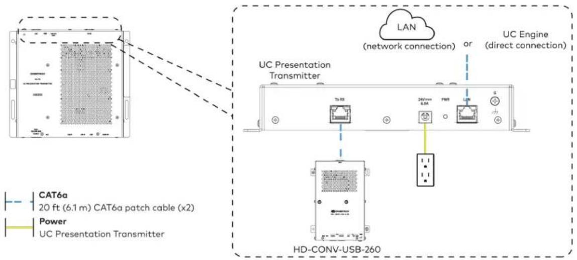
text_image
CAT6a 20 ft (6.1 m) CAT6a patch cable (x2) Power UC Presentation Transmitter LAN (network connection) or UC Engine (direct connection) UC Presentation Transmitter 245 mm 0.0A FWR LUN HD-CONV-USB-260- Connect the touch screen to the bottom of the UC Presentation Transmitter.

text_image
CAT5e 7 ft (2.1 m) CAT5e cable
text_image
For firmware loading For UC-MMX30 systems only UC Presentation Transmitter Polo+ F2E 30W MAX ACC USB A or Wall Mount Touch Screen Tabletop Touch screen- Connect a laptop to either the USB port or both the HDMI and USB B ports on the bottom of the UC Presentation Transmitter. Select a connection type based on the available ports on the user's laptop.
NOTE: If the USB port is used along with either the HDMI or USB B port, the UC Presentation Transmitter will communicate via the USB port by default.
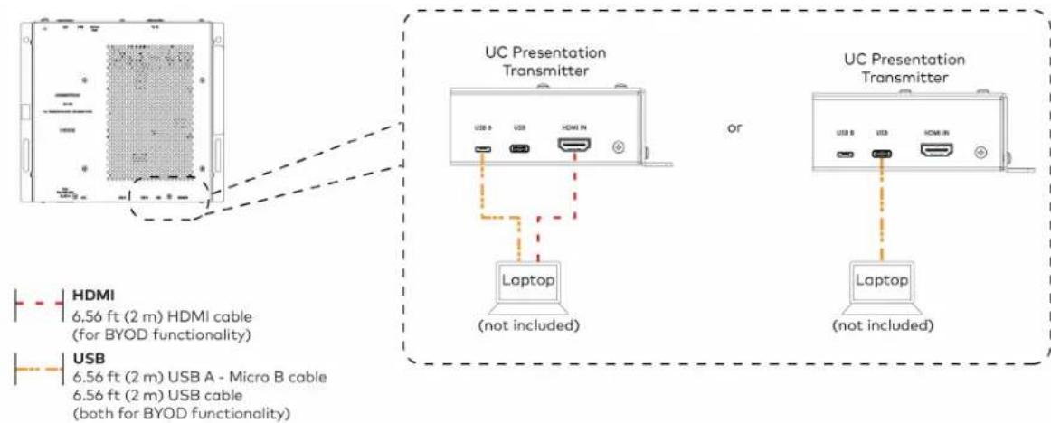
text_image
UC Presentation Transmitter or Laptop (not included) UC Presentation Transmitter Laptop (not included) HDMI 6.56 ft (2 m) HDMI cable (for BYOD functionality) USB 6.56 ft (2 m) USB A - Micro B cable 6.56 ft (2 m) USB cable (both for BYOD functionality)- Bundle the cables to the bracket assembly with the integrated cable tie wraps. The cable tie wraps are reusable.
Apply Power
Press the power button on the bottom of the UC Engine and apply power to all of the other devices in the system.
NOTE: If a direct connection was made during installation, skip to Configure the System on page 144.
- On a computer, enter the IP address of the touch screen into a web browser. Log in and navigate to Settings > Applications.
NOTES:
- The touch screen (via the PoE injector) and computer must be on the same network switch and VLAN.
-
A login with administrative rights for the touch screen is required.
-
Enter the following information in the appropriate fields:
- Teams Video PC Address: Enter the IP address or hostname of the UC Engine.
NOTE: The hostname is printed on a label affixed to the UC Engine (mounted on the UC bracket assembly).
- Teams Video PC Port: By default, port number 49500 is used. If a different port number h been configured on the UC Engine, enter that port number instead.
- Teams Video Username: Enter the login username for the UC Engine. (The default username is "admin".)
-
Teams Video Password: Enter the login password for the UC Engine. (The default password is "sfb".)
-
Select Save Changes.
Configure the System
Use the touch screen and your Microsoft Teams credentials to configure the UC Engine, as described in Configuration on page 222. For detailed information on deploying Microsoft Teams Rooms, refer to the Microsoft Teams Rooms documentation.
UC-C100-T and UC-C100-T-WM Connections
Minimum Requirements
Ensure that the below requirements are met prior to setting up the system.
• A certified USB Camera (not included).
- A certified, AEC-enabled USB speakerphone or DSP device (not included).
- A video display (not included) connected to the UC Engine. A second display is optional.
• A Microsoft Teams Rooms provisioned account (not included).
NOTE: Unless otherwise indicated in this section, the connection procedure is the same for UC-C100-T and UC-C100-T-WM.
Identify the UC Bracket Assembly
The UC Bracket Assembly is available in two models. Identify the model included with your Crestron Flex system. Tap or click the corresponding image below to navigate to the appropriate connection instructions.
UC Bracket Assembly with HD-CONV-USB-200 UC Bracket Assembly with HD-CONV-USB-300

natural_image
Technical line drawing of a mechanical or electrical assembly with no visible text, numbers, or symbols.
text_image
Technical schematic diagram of a device with labeled components and wiring connectionsSystem Overview
For UC Bracket Assembly with HD-CONV-USB-200
When connections are complete, the system appears as shown below. Refer to Make Connections on page 147 for detailed connection instructions.
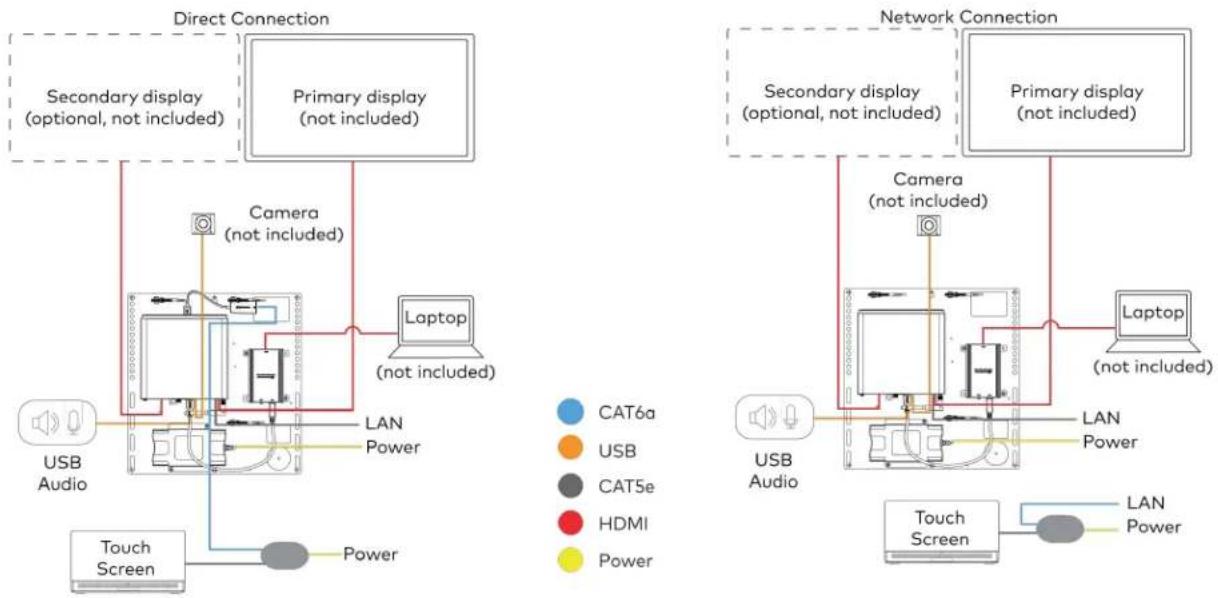
flowchart
graph TD
    subgraph Direct Connection
        A["USB Audio"] --> B["Camera (not included)"]
        B --> C["Laptop (not included)"]
        C --> D["Primary display (not included)"]
        D --> E["Secondary display (optional, not included)"]
        E --> F["Touch Screen"]
        F --> G["Camera (not included)"]
        G --> H["Laptop (not included)"]
    end

    subgraph Network Connection
        I["USB Audio"] --> J["Camera (not included)"]
        J --> K["Laptop (not included)"]
        K --> L["Primary display (not included)"]
        L --> M["Secondary display (optional, not included)"]
        M --> N["Touch Screen"]
        N --> O["Camera (not included)"]
        O --> P["Laptop (not included)"]
        P --> Q["Primary display (not included)"]
        Q --> R["Secondary display (optional, not included)"]
        R --> S["Touch Screen"]
        S --> T["Camera (not included)"]
        T --> U["Laptop (not included)"]
    end

    style Direct Connection fill:#f9f,stroke:#333
    style Network Connection fill:#bbf,stroke:#333
For UC Bracket Assembly with HD-CONV-USB-300
When connections are complete, the system appears as shown below. Refer to Make Connections on page 147 for detailed connection instructions.
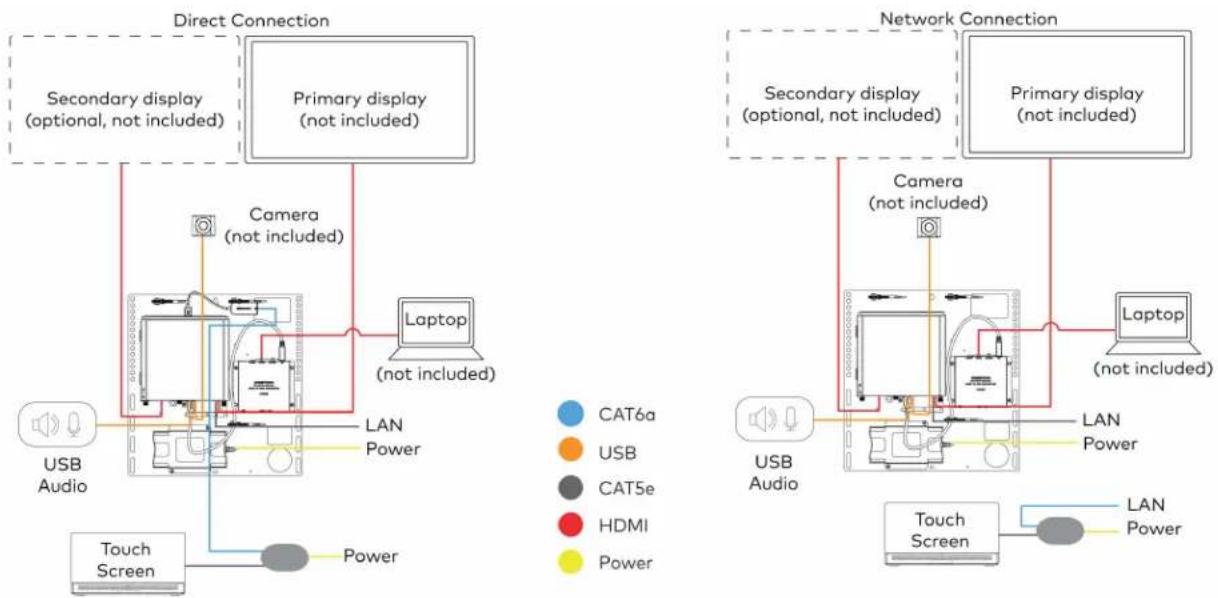
flowchart
graph TD
    subgraph Direct Connection
        A["Primary display (not included)"]
        B["Camera (not included)"]
        C["Laptop (not included)"]
        D["USB Audio"]
        E["Touch Screen"]
    end

    subgraph Network Connection
        F["Primary display (not included)"]
        G["Camera (not included)"]
        H["Laptop (not included)"]
        I["USB Audio"]
        J["Touch Screen"]
    end

    A --> B
    B --> C
    C --> D
    D --> E
    E --> F
    F --> G
    G --> H
    H --> I
    I --> J
    style A fill:#f9f,stroke:#333
    style B fill:#f9f,stroke:#333
    style C fill:#ccf,stroke:#333
    style D fill:#cfc,stroke:#333
    style E fill:#fcc,stroke:#333
    style F fill:#cff,stroke:#333
    style G fill:#ffc,stroke:#333
    style H fill:#fcf,stroke:#333
    style I fill:#cff,stroke:#333
NOTE: For reference, the UC Bracket Assembly is shown with the HD-CONV-USB-200 in the following connection diagrams. Unless otherwise indicated in this guide, the connections remain the same for the UC Bracket Assembly with HD-CONV-USB-200 and HD-CONV-USB-300.
- Make UC Engine connections as shown in the following illustrations. The touch screen can communicate with the UC Engine over a direct connection or a network connection. Select one of the connection types as described below.
- Make a direct connection for simple installation and setup. Only use the direct connect adapter to connect the touch screen's PoE injector to the UC Engine. Do not use the direct connect adapter to connect the UC Engine to the network.
Direct Connection
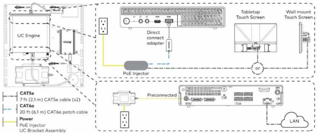
flowchart
graph TD
    A["UC Engine"] --> B["Tabletop Touch Screen"]
    B --> C["Wall mount Touch Screen"]
    D["PoE Injector"] --> E["Direct connect adapter"]
    E --> B
    F["Preconnected"] --> G["BAT5e 7 ft (2.1 m) CAT5e cable (x2)"]
    F --> H["BAT6a 20 ft (6.1 m) CAT6a patch cable"]
    F --> I["Power PoE Injector UC Bracket Assembly"]
    J["LAN"] --> K["Data Port"]
    style A fill:#f9f,stroke:#333
    style B fill:#ccf,stroke:#333
    style C fill:#cfc,stroke:#333
    style D fill:#fcc,stroke:#333
    style E fill:#ffc,stroke:#333
    style F fill:#cff,stroke:#333
    style G fill:#ffc,stroke:#333
    style H fill:#ffc,stroke:#333
    style I fill:#ffc,stroke:#333
    style J fill:#fcc,stroke:#333
- Make a network connection if the system is to be managed by the XiO Cloud® service.
NOTE: When a network connection is used, disconnect the direct connect adapter from the UC Engine.
Network Connection

flowchart
graph TD
    A["UC Engine"] --> B["PoE Injector"]
    B --> C["Tabletop Touch Screen"]
    C --> D["Wall Mount Touch Screen"]
    D --> E["Preconnected"]
    E --> F["Power PoE Injector"]
    F --> G["CAT5e 7 ft (2.1 m) CAT5e cable (x2)"]
    F --> H["CAT6a 20 ft (6.1 m) CAT6a patch cable"]
    F --> I["LAN"]
    B --> J["Remove the Direct Connect adapter"]
    J --> K["LAN"]
    style A fill:#f9f,stroke:#333
    style B fill:#ccf,stroke:#333
    style C fill:#cfc,stroke:#333
    style D fill:#fcc,stroke:#333
    style E fill:#cff,stroke:#333
    style F fill:#ffc,stroke:#333
    style G fill:#cfc,stroke:#333
    style H fill:#fcc,stroke:#333
    style I fill:#ffc,stroke:#333
- Connect a USB audio source (accessory) and displays to the UC Engine.
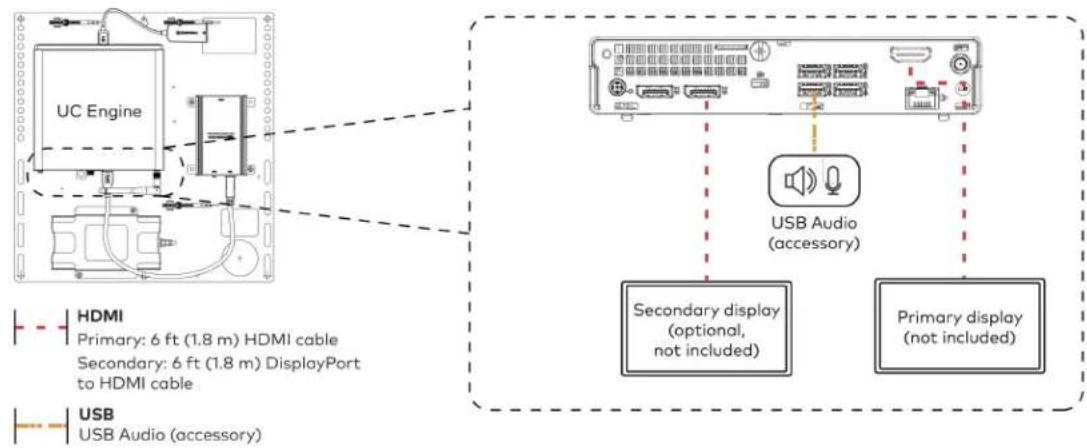
text_image
UC Engine HDMI Primary: 6 ft (1.8 m) HDMI cable Secondary: 6 ft (1.8 m) DisplayPort to HDMI cable USB USB Audio (accessory) USB Audio (accessory) Secondary display (optional, not included) Primary display (not included)- Connect a camera (not included) to the UC Engine as shown in the image below. Do not connect the camera to any of the other USB ports.
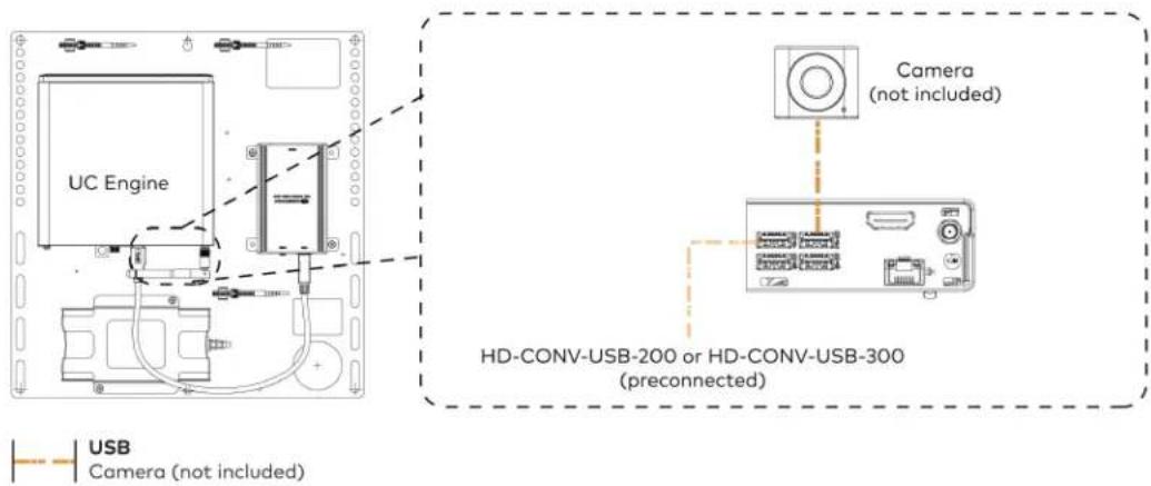
text_image
UC Engine Camera (not included) HD-CONV-USB-200 or HD-CONV-USB-300 (preconnected) USB Camera (not included)- Connect a laptop to the HD-CONV-USB-200 or HD-CONV-USB-300.

text_image
UC Bracket Assembly with HD-CONV-USB-200 Laptop (not included) HD-CONV-USB-200 or UC Bracket Assembly with HD-CONV-USB-300 Laptop (not included) HD-CONV-USB-300 HDMI 20 ft (6.1 m) HDMI cable- Bundle the cables to the bracket assembly with the integrated cable tie wraps. The cable tie wraps are reusable.
Apply Power
Press the power button on the bottom of the UC Engine and apply power to all of the other devices in the system.
Configure the Touch Screen
NOTE: If a direct connection was made during installation, skip to Configure the System on page 150.
- On a computer, enter the IP address of the touch screen into a web browser. Log in and navigate to Settings > Applications.
NOTES:
- The touch screen (via the PoE injector) and computer must be on the same network switch and VLAN.
-
A login with administrative rights for the touch screen is required.
-
Enter the following information in the appropriate fields:
- Teams Video PC Address: Enter the IP address or hostname of the UC Engine.
NOTE: The hostname is printed on a label affixed to the UC Engine (mounted on the UC bracket assembly).
- Teams Video PC Port: By default, port number 49500 is used. If a different port number h been configured on the UC Engine, enter that port number instead.
- Teams Video Username: Enter the login username for the UC Engine. (The default username is "admin".)
- Teams Video Password: Enter the login password for the UC Engine. (The default password is "sfb".)
3. Select Save Changes.
Configure the System
Use the touch screen and your Microsoft Teams credentials to configure the UC Engine, as described in Configuration on page 222. For detailed information on deploying Microsoft Teams Rooms, refer to the Microsoft Teams Rooms documentation.
UC-CX100-T and UC-CX100-T-WM Connections
Minimum Requirements
Ensure that the below requirements are met prior to setting up the system.
• A certified USB Camera (not included).
- A certified, AEC-enabled USB speakerphone or DSP device (not included).
- A video display (not included) connected to the UC Engine. A second display is optional.
• A Microsoft Teams Rooms provisioned account (not included).
NOTE: Unless otherwise indicated in this section, the connection procedure is the same for UC-CX100-T and UC-CX100-T-WM.
System Overview
When connections are complete, the system appears as shown below. The laptop connections shown below may vary based on the selected connection method. Refer to Make Connections on page 152 for detailed connection instructions.

flowchart
graph TD
    subgraph Direct Connection
        A["Primary display (not included)"]
        B["Camera (not included)"]
        C["Touch Screen"]
        D["Laptop (not included)"]
        E["LAN"]
        F["USB Audio"]
    end

    subgraph Network Connection
        G["Primary display (not included)"]
        H["Camera (not included)"]
        I["Touch Screen"]
        J["Laptop (not included)"]
        K["LAN"]
        L["USB Audio"]
    end

    A --> B --> C --> D --> E --> F --> G --> H --> I --> J --> K
    B --> C --> D --> E --> F --> G --> H --> I --> J --> K
    style A fill:#f9f,stroke:#333
    style B fill:#ccf,stroke:#333
    style C fill:#cfc,stroke:#333
    style D fill:#fcc,stroke:#333
    style E fill:#cff,stroke:#333
    style F fill:#ffc,stroke:#333
    style G fill:#cfc,stroke:#333
    style H fill:#fcc,stroke:#333
    style I fill:#ffc,stroke:#333
    style J fill:#fcc,stroke:#333
Make Connections
- Make UC Engine connections as shown in the following illustrations. The UC Presentation Transmitter can communicate with the UC Engine over a direct connection or a network connection. Select one of the connection types as described below.
- Make a direct connection for simple installation and setup. Only use the direct connect adapter to connect the UC Presentation Transmitter to the UC Engine. Do not use the direct connect adapter to connect the UC Engine to the network.
Direct Connection
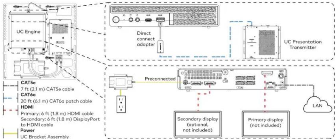
flowchart
graph TD
    A["UC Engine"] --> B["Direct connect adapter"]
    B --> C["Preconnected"]
    C --> D["Secondary display (optional, not included)"]
    C --> E["Primary display (not included)"]
    F["UC Presentation Transmitter"] --> G["LAN"]
    H["CAT5e 7 ft (2.1 m) CAT5e cable"] --> I["CAT6a 20 ft (6.1 m) CAT6a patch cable"]
    H --> J["HDMI Primary: 6 ft (1.8 m) HDMI cable"]
    H --> K["Secondary: 6 ft (1.8 m) DisplayPort to HDMI cable"]
    H --> L["Power UC Bracket Assembly"]
    style A fill:#f9f,stroke:#333
    style F fill:#ccf,stroke:#333
    style H fill:#cfc,stroke:#333
    style I fill:#fcc,stroke:#333
    style J fill:#cff,stroke:#333
    style K fill:#ffc,stroke:#333
    style L fill:#fcc,stroke:#333
- Make a network connection if the system is to be managed by the XiO Cloud® service.
NOTE: When a network connection is used, disconnect the direct connect adapter from the UC Engine.
Network Connection
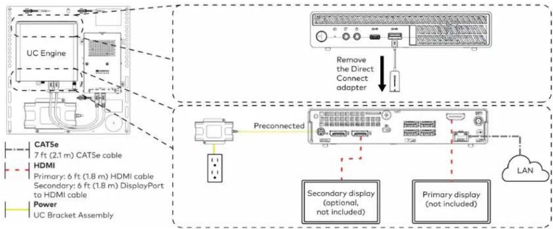
flowchart
graph TD
    A["UC Engine"] -->|Preconnected| B["Preconnected"]
    B --> C["Secondary display (optional, not included)"]
    B --> D["Primary display (not included)"]
    C --> E["LAN"]
    D --> E
    F["CAT5e 7 ft (2.1 m) CAT5e cable"] --> A
    G["HDMI Primary: 6 ft (1.8 m) HDMI cable"] --> A
    H["Secondary: 6 ft (1.8 m) DisplayPort to HDMI cable"] --> A
    I["Power UC Bracket Assembly"] --> A
    J["Remove the Direct Connect adapter"] --> K["Device with ports and indicator"]
- Connect the power supply, USB audio (accessory), and a camera (not included) to the bottom of the content ingest device (HD-CONV-USB-260). Connect the power supply to an AC power outlet.

text_image
UC Engine CAMERA (USB 3.0, B) CAM (USB 3.0, A) AUX (USB 2.0, A) CONTENT (USB 3.0, B) 24V 1.25A (Barrel jack) Preconnected to UC Engine HD-CONV-USB-260 Power supply USB Audio (accessory) Camera (not included) USB Camera (not included) USB Audio (accessory)- Connect power and the content ingest device (HD-CONV-USB-260) to the top of the UC Presentation Transmitter. Connect the UC Engine or LAN to make a direct or network connection as described in step 1.
NOTE: If a longer cable between the UC Presentation Transmitter and the HD-CONV-USB-260 is needed, use a DigitalMedia™ Ultra cable only. The maximum supported cable length is 300 ft (91.4 m).
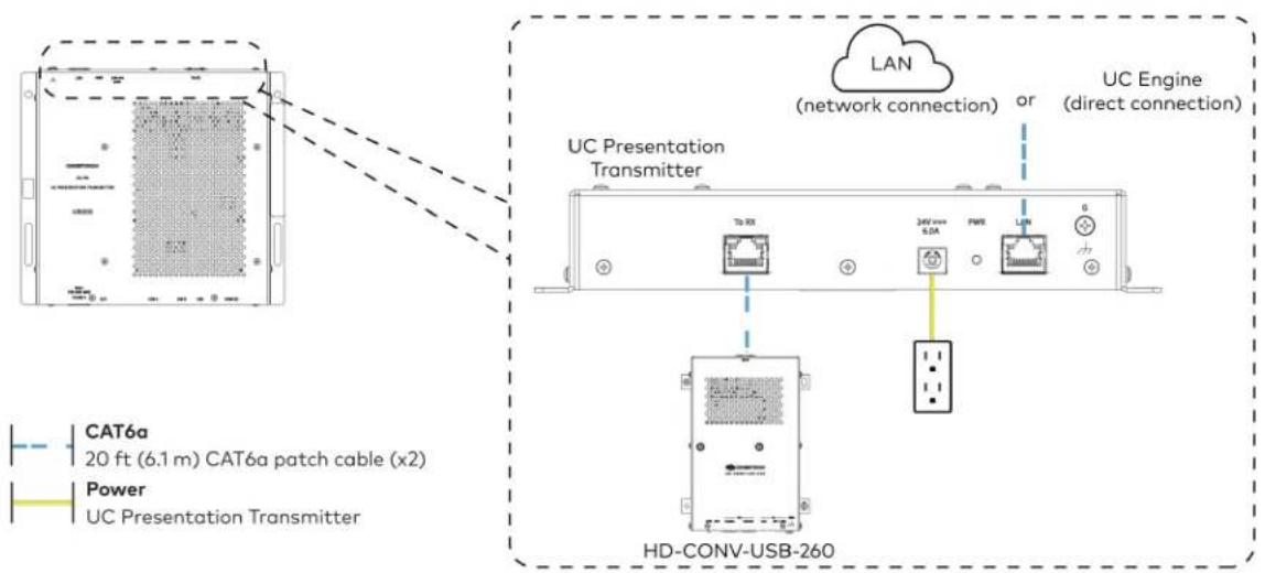
text_image
CAT6a 20 ft (6.1 m) CAT6a patch cable (x2) Power UC Presentation Transmitter LAN (network connection) or UC Engine (direct connection) UC Presentation Transmitter TD RX 34V max 6.0A PWB LAN 6 HD-CONV-USB-260- Connect the touch screen to the bottom of the UC Presentation Transmitter.

text_image
CAT5e 7 ft (2.1 m) CAT5e cable
text_image
For firmware loading For UC-MMX30 systems only UC Presentation Transmitter Polo+ F2E 30W MAX ACC USB A or Wall Mount Touch Screen Tabletop Touch screen- Connect a laptop to either the USB port or both the HDMI and USB B ports on the bottom of the UC Presentation Transmitter. Select a connection type based on the available ports on the user's laptop.
NOTE: If the USB port is used along with either the HDMI or USB B port, the UC Presentation Transmitter will communicate via the USB port by default.

text_image
UC Presentation Transmitter or Laptop (not included) UC Presentation Transmitter Laptop (not included) HDMI 6.56 ft (2 m) HDMI cable (for BYOD functionality) USB 6.56 ft (2 m) USB A - Micro B cable 6.56 ft (2 m) USB cable (both for BYOD functionality)- Bundle the cables to the bracket assembly with the integrated cable tie wraps. The cable tie wraps are reusable.
Apply Power
Press the power button on the bottom of the UC Engine and apply power to all of the other devices in the system.
NOTE: If a direct connection was made during installation, skip to Configure the System on page 155.
- On a computer, enter the IP address of the touch screen into a web browser. Log in and navigate to Settings > Applications.
NOTES:
- The touch screen (via the PoE injector) and computer must be on the same network switch and VLAN.
-
A login with administrative rights for the touch screen is required.
-
Enter the following information in the appropriate fields:
- Teams Video PC Address: Enter the IP address or hostname of the UC Engine.
NOTE: The hostname is printed on a label affixed to the UC Engine (mounted on the UC bracket assembly).
- Teams Video PC Port: By default, port number 49500 is used. If a different port number h been configured on the UC Engine, enter that port number instead.
- Teams Video Username: Enter the login username for the UC Engine. (The default username is "admin".)
-
Teams Video Password: Enter the login password for the UC Engine. (The default password is "sfb".)
-
Select Save Changes.
Configure the System
Use the touch screen and your Microsoft Teams credentials to configure the UC Engine, as described in Configuration on page 222. For detailed information on deploying Microsoft Teams Rooms, refer to the Microsoft Teams Rooms documentation.
UC-MM30-T and UC-MM30-T-I Connections
Minimum Requirements
Ensure that the below requirements are met prior to setting up the system.
- A video display (not included) connected to the UC Engine. A second display is optional.
• A Microsoft Teams Rooms provisioned account (not included).
NOTE: Unless otherwise indicated in this section, the connection procedure is the same for UC-MM30-T and UC-MM30-T-I.
Identify the UC Bracket Assembly
The UC Bracket Assembly is available in two models. Identify the model included with your Crestron Flex system. Tap or click the corresponding image below to navigate to the appropriate connection instructions.
UC Bracket Assembly with HD-CONV-USB-200 UC Bracket Assembly with HD-CONV-USB-300

natural_image
Technical line drawing of a mechanical or electrical assembly with no visible text, numbers, or symbols.
text_image
Technical schematic diagram of a device with labeled components and wiring connectionsSystem Overview
For UC Bracket Assembly with HD-CONV-USB-200
When connections are complete, the system appears as shown below. Refer to Make Connections on page 158 for detailed connection instructions.
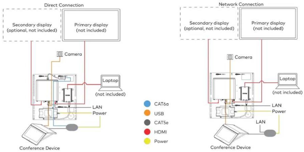
flowchart
graph TD
    subgraph Direct Connection
        A["Secondary display (optional, not included)"]
        B["Primary display (not included)"]
        C["Laptop (not included)"]
        D["Camera"]
        E["Conference Device"]
    end

    subgraph Network Connection
        F["Secondary display (optional, not included)"]
        G["Primary display (not included)"]
        H["Laptop (not included)"]
        I["Camera"]
        J["Conference Device"]
    end

    style Direct Connection fill:#f9f,stroke:#333
    style Network Connection fill:#bbf,stroke:#333
For UC Bracket Assembly with HD-CONV-USB-300
When connections are complete, the system appears as shown below. Refer to Make Connections on page 158 for detailed connection instructions.

flowchart
graph TD
    subgraph Direct Connection
        A["Secondary display (optional, not included)"]
        B["Primary display (not included)"]
        C["Laptop (not included)"]
        D["Camera"]
        E["Conference Device"]
    end

    subgraph Network Connection
        F["Secondary display (optional, not included)"]
        G["Primary display (not included)"]
        H["Laptop (not included)"]
        I["Camera"]
        J["Conference Device"]
    end

    style Direct Connection fill:#f9f,stroke:#333
    style Network Connection fill:#bbf,stroke:#333
NOTE: For reference, the UC Bracket Assembly is shown with the HD-CONV-USB-200 in the following connection diagrams. Unless otherwise indicated in this guide, the connections remain the same for the UC Bracket Assembly with HD-CONV-USB-200 and HD-CONV-USB-300.
- Make UC Engine connections as shown in the following illustrations. The conference device can communicate with the UC Engine over a direct connection or a network connection. Select one of the connection types as described below.
- Make a direct connection for simple installation and setup. Only use the direct connect adapter to connect the conference device to the UC Engine. Do not use the direct connect adapter to connect the UC Engine to the network.
Direct Connection
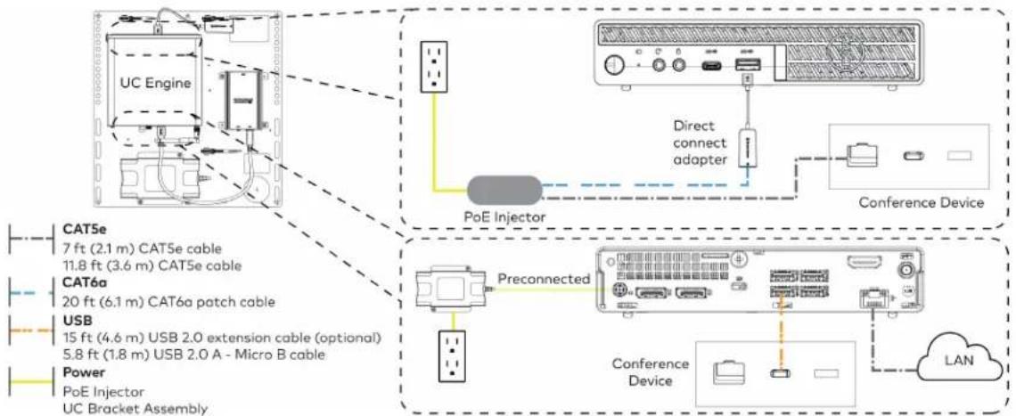
flowchart
graph TD
    A["UC Engine"] --> B["POE Injector"]
    B --> C["Conference Device"]
    C --> D["Conference Device"]
    D --> E["LAN"]
    F["Preconnected"] --> G["Cooper Unit"]
    H["Direct connect adapter"] --> I["Conference Device"]
    J["Power"] --> K["POE Injector"]
    L["USB"] --> M["2.0 extension cable optional"]
    N["CAT6a patch cable"] --> O["2.1 m CAT5e cable"]
    P["CAT5e"] --> Q["7 ft (2.1 m) CAT5e cable"]
    R["USB"] --> S["2.1 m 2.0 extension cable"]
    T["POWER"] --> U["1.8 m USB 2.0 A - Micro B cable"]
- Make a network connection if the system is to be managed by the XiO Cloud® service.
NOTE: When a network connection is used, disconnect the direct connect adapter from the UC Engine.
Network Connection
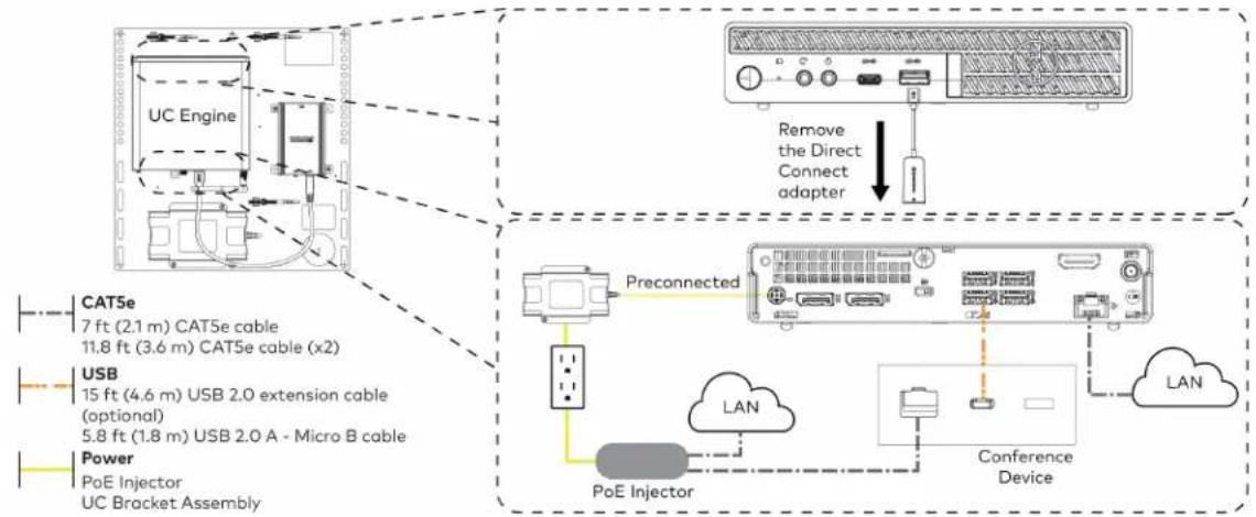
flowchart
graph TD
    A["UC Engine"] --> B["Preconnected Device"]
    C["Remove the Direct Connect adapter"] --> B
    D["POE Injector"] --> E["Conference Device"]
    F["USB"] --> G["Preconnected Device"]
    H["Power"] --> I["Preconnected Device"]
    J["CAT5e"] --> K["7 ft (2.1 m) CAT5e cable"]
    J --> L["11.8 ft (3.6 m) CAT5e cable (x2)"]
    M["USB"] --> N["15 ft (4.6 m) USB 2.0 extension cable (optional)"]
    M --> O["5.8 ft (1.8 m) USB 2.0 A - Micro B cable"]
    P["Power"] --> Q["PoE Injector"]
    P --> R["UC Bracket Assembly"]
- Connect displays to the UC Engine.
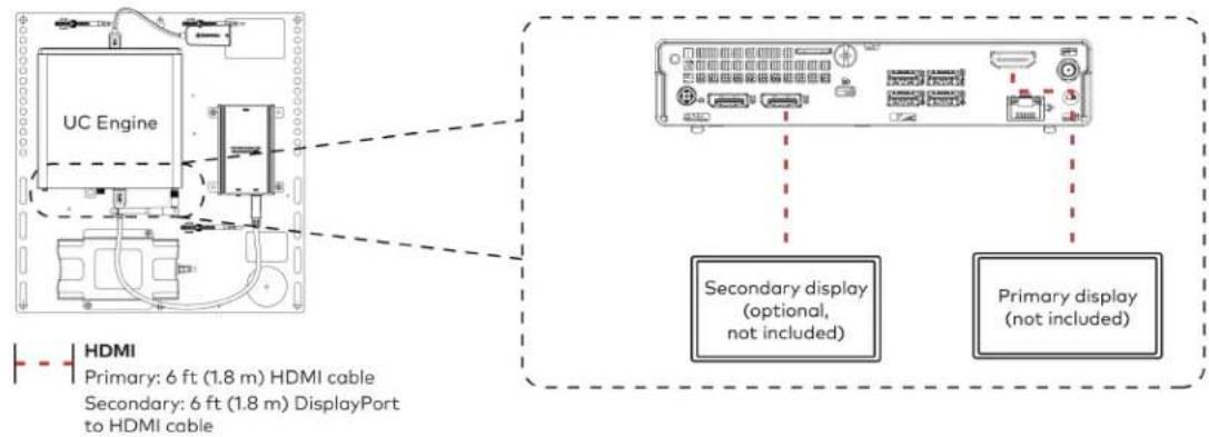
text_image
UC Engine HDMI Primary: 6 ft (1.8 m) HDMI cable Secondary: 6 ft (1.8 m) DisplayPort to HDMI cable Secondary display (optional, not included) Primary display (not included)- Connect the camera to the UC Engine as shown in the image below. Do not connect the camera to any of the other USB ports.
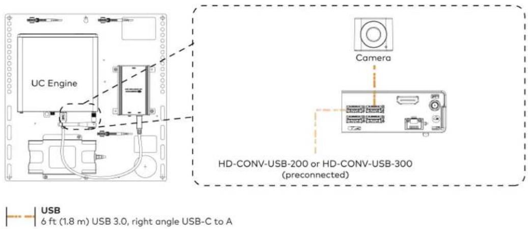
text_image
UC Engine Camera HD-CONV-USB-200 or HD-CONV-USB-300 (preconnected) USB 6 ft (1.8 m) USB 3.0, right angle USB-C to A- Connect a laptop to the HD-CONV-USB-200 or HD-CONV-USB-300.
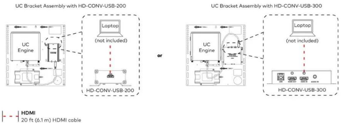
text_image
UC Bracket Assembly with HD-CONV-USB-200 Laptop (not included) or UC Bracket Assembly with HD-CONV-USB-300 UC Engine Laptop (not included) HD-CONV-USB-300 HDMI 20 ft (6.1 m) HDMI cable- Bundle the cables to the bracket assembly with the integrated cable tie wraps. The cable tie wraps are reusable.
Apply Power
Press the power button on the bottom of the UC Engine and apply power to all of the other devices in the system.
Configure the Conference Device
NOTE: If a Direct Connection was made between the conference device and the UC Engine, skip to Configure the System on page 161.
- On a computer, enter the IP address found in the conference device's settings into a web browser.
NOTES:
- The device and computer must be on the same network switch and VLAN.
-
A login with administrative rights for the device is required.
-
Log in to the device and navigate to DEVICE > Applications.
-
Enter the following information in the appropriate fields:
- Teams Video PC Address: Enter the IP address or hostname of the UC Engine.
NOTE: The hostname is printed on a label affixed to the UC Engine.
- Teams Video PC Port: By default, port number 49500 is used. If a different port number h been configured on the UC Engine, enter that port number instead.
- Teams Video Username: Enter the login username for the UC Engine. (The default username is "admin".)
- Teams Video Password: Enter the login password for the UC Engine. (The default password is "sfb".)
4. Select Save Changes.
Configure the System
Use the conference device and your Microsoft Teams credentials to configure the UC Engine, as described in Configuration on page 222. For detailed information on deploying Microsoft Teams Rooms, refer to the Microsoft Teams Rooms documentation.
NOTE: Microsoft Teams does not support emergency calling in Japan. For more information on emergency calling from Microsoft Teams, refer to Manage emergency calling.
Factory Reset
A factory reset may be performed when troubleshooting the conference device.
To perform a factory reset on the conference device:
- Power cycle the device by disconnecting and reconnecting the CAT5e cable from the conference device.
- When the device powers on and the LEDs flash green, tap the button below the Crestron® logo 10 times. A factory reset confirmation screen appears.

text_image
G00000000 ↓Tap x10
- Tap one of the mute buttons to move the selector on the factory reset confirmation screen to Yes. Tap the button below the Crestron logo to confirm the factory reset.

text_image
Tap to move selector Tap to move selector Tap to confirm- The device will reboot. Configure the device as described in Configure the Conference Device section.
UC-MMX30-T and UC-MMX30-T-I Connections
Minimum Requirements
Ensure that the below requirements are met prior to setting up the system.
- A video display (not included) connected to the UC Engine. A second display is optional.
• A Microsoft Teams Rooms provisioned account (not included).
NOTE: Unless otherwise indicated in this section, the connection procedure is the same for UC-MMX30-T and UC-MMX30-T-I.
System Overview
When connections are complete, the system appears as shown below. The laptop connections shown below may vary based on the selected connection method. Refer to Make Connections on page 164 for detailed connection instructions.
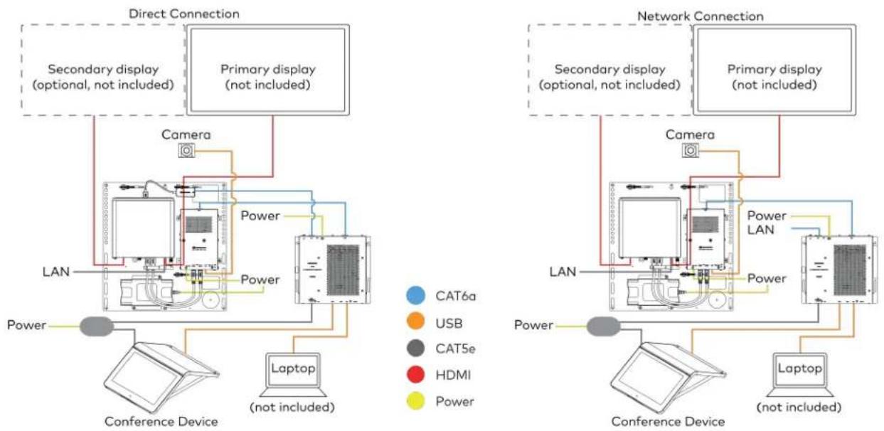
flowchart
graph TD
    subgraph Direct Connection
        A["Secondary display (optional, not included)"]
        B["Primary display (not included)"]
        C["Camera"]
        D["Power"]
        E["Laptop (not included)"]
        F["LAN"]
    end

    subgraph Network Connection
        G["Secondary display (optional, not included)"]
        H["Primary display (not included)"]
        I["Camera"]
        J["Power LAN"]
        K["Laptop (not included)"]
        L["LAN"]
    end

    A --> C
    B --> D
    C --> E
    D --> F
    E --> G
    F --> H
    G --> I
    H --> J
    I --> K
    style A fill:#f9f,stroke:#333
    style B fill:#f9f,stroke:#333
    style C fill:#ccf,stroke:#333
    style D fill:#ccf,stroke:#333
    style E fill:#ccf,stroke:#333
    style F fill:#ccf,stroke:#333
    style G fill:#cfc,stroke:#333
    style H fill:#cfc,stroke:#333
    style I fill:#cfc,stroke:#333
    style J fill:#cfc,stroke:#333
    style K fill:#cfc,stroke:#333
Make Connections
- Make UC Engine connections as shown in the following illustrations. The UC Presentation Transmitter can communicate with the UC Engine over a direct connection or a network connection. Select one of the connection types as described below.
- Make a direct connection for simple installation and setup. Only use the direct connect adapter to connect the UC Presentation Transmitter to the UC Engine. Do not use the direct connect adapter to connect the UC Engine to the network.
Direct Connection
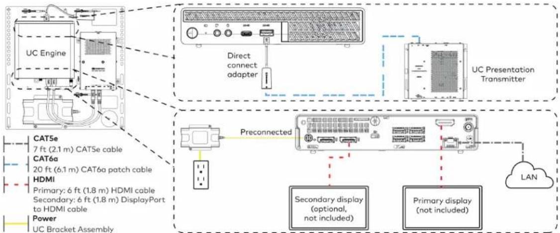
flowchart
graph TD
    A["UC Engine"] --> B["Direct connect adapter"]
    B --> C["UC Presentation Transmitter"]
    D["Preconnected"] --> E["Secondary display (optional, not included)"]
    D --> F["Primary display (not included)"]
    G["TCAT5e 7 ft (2.1 m) CAT5e cable"] --> H["HDMI Primary: 6 ft (1.8 m) HDMI cable"]
    I["TCAT6a 20 ft (6.1 m) CAT6a patch cable"] --> H
    J["TCAT6b Primary: 6 ft (1.8 m) DisplayPort to HDMI cable"] --> H
    K["TCAT6c Primary: 6 ft (1.8 m) HDMI cable"] --> H
    L["TCAT6d Primary: 6 ft (1.8 m) DisplayPort to HDMI cable"] --> H
    M["TCAT6e Primary: 6 ft (2.1 m) CAT6e cable"] --> N["HDMI Primary: 6 ft (1.8 m) HDMI cable"]
    O["TCAT6f Primary: 6 ft (2.1 m) CAT6f patch cable"] --> N
    P["TCAT6g Primary: 6 ft (1.8 m) HDMI cable"] --> N
    Q["TCAT6h Primary: 6 ft (1.8 m) HDMI cable"] --> N
    R["TCAT6i Primary: 6 ft (1.8 m) HDMI cable"] --> N
    S["TCAT6j Primary: 6 ft (1.8 m) HDMI cable"] --> N
    T["TCAT6k Primary: 6 ft (1.8 m) HDMI cable"] --> N
    U["TCAT6l Primary: 6 ft (1.8 m) HDMI cable"] --> N
    V["TCAT6m Primary: 6 ft (1.8 m) HDMI cable"] --> N
    W["TCAT6n Primary: 6 ft (1.8 m) HDMI cable"] --> N
    X["TCAT6o Primary: 6 ft (1.8 m) HDMI cable"] --> N
    Y["TCAT6p Primary: 6 ft (1.8 m) HDMI cable"] --> N
    Z["TCAT6q Primary: 6 ft (1.8 m) HDMI cable"] --> N
    AA["TCAT6r Primary: 6 ft (1.8 m) HDMI cable"] --> N
    AB["TCAT6s Primary: 6 ft (1.8 m) HDMI cable"] --> N
    AC["TCAT6t Primary: 6 ft (1.8 m) HDMI cable"] --> N
    AD["TCAT6u Primary: 6 ft (1.8 m) HDMI cable"] --> N
    AE["TCAT6v Primary: 6 ft (1.8 m) HDMI cable"] --> N
    AF["TCAT6w Primary: 6 ft (1.8 m) HDMI cable"] --> N
    AG["TCAT6x Primary: 6 ft (1.8 m) HDMI cable"] --> N
    AH["TCAT6y Primary: 6 ft (1.8 m) HDMI cable"] --> N
    AI["TCAT6z Primary: 6 ft (1.8 m) HDMI cable"] --> N
    AJ["TCAT6w Primary: 6 ft (1.8 m) HDMI cable"] --> N
    AK["TCAT6w Primary: 6 ft (1.8 m) HDMI cable"] --> N
    AL["TCAT6w Primary: 6 ft (1.8 m) HDMI cable"] --> N
    AM["TCAT6w Primary: 6 ft (1.8 m) HDMI cable"] --> N
    AN["TCAT6w Primary: 6 ft (1.8 m) HDMI cable"] --> N
    AO["TCAT6w Primary: 6 ft (1.8 m) HDMI cable"] --> N
    AP["TCAT6w Primary: 6 ft (1.8 m) HDMI cable"] --> N
    AQ["TCAT6w Primary: 6 ft (1.8 m) HDMI cable"] --> N
    AR["TCAT6w Primary: 6 ft (1.8 m) HDMI cable"] --> N
    AS["TCAT6w Primary: 6 ft (1.8 m) HDMI cable"] --> N
    AT["TCAT6w Primary: 6 ft (1.8 m) HDMI cable"] --> N
    AU["TCAT6w Primary: 6 ft (1.8 m) HDMI cable"] --> N
    AV["TCAT6w Primary: 6 ft (1.8 m) HDMI cable"] --> N
    AW["TCAT6w Primary: 6 ft (1.8 m) HDMI cable"] --> N
    AX["TCAT6w Primary: 6 ft (1.8 m) HDMI cable"] --> N
    AY["TCAT5e Primary: 7 ft (2.1 m) CAT5e cable"] --> AZ["HDMI Primary: 20 ft (6.1 m) CAT5e patch cable"]
    BA["TCAT5e Primary: 20 ft (6.1 m) CAT5e patch cable"] --> BB["HDMI Primary: 20 ft (2.1 m) CAT5e cable"]
    BC["TCAT5e Primary: 20 ft (2.1 m) CAT5e patch cable"] --> BD["HDMI Primary: 20 ft (2.1 m) CAT5e cable"]
    BE["TCAT5e Primary: 20 ft (2.1 m) CAT5e patch cable"] --> BF["HDMI Primary: 20 ft (2.1 m) CAT5e cable"]
    BG["TCAT5e Primary: 20 ft (2.1 m) CAT5e patch cable"] --> BH["HDMI Primary: 20 ft (2.1 m) CAT5e cable"]
    BI["TCAT5e Primary: 20 ft (2.1 m) CAT5e patch cable"] --> BJ["HDMI Primary: 20 ft (2.1 m) CAT5e cable"]
    BK["TCAT5e Primary: 20 ft (2.1 m) CAT5e patch cable"] --> BL["HDMI Primary: 20 ft (2.1 m) CAT5e cable"]
    BM["TCAT5e Primary: 20 ft (2.1 m) CAT5e patch cable"] --> BN["HDMI Primary: 20 ft (2.1 m) CAT5e cable"]
    BO["TCAT5e Primary: 20 ft (2.1 m) CAT5e patch cable"] --> BP["HDMI Primary: 20 ft (2.1 m) CAT5e cable"]
    BQ["TCAT5e Primary: 20 ft (2.1 m) CAT5e patch cable"] --> BR["HDMI Primary: 20 ft (2.1 m) CAT5e cable"]
    BS["TCAT5e Primary: 20 ft (2.1 m) CAT5e patch cable"] --> BT["HDMI Primary: 20 ft (2.1 m) CAT5e cable"]
    BU["TCAT5e Primary: 20 ft (2.1 m) CAT5e patch cable"] --> BV["HDMI Primary: 20 ft (2.1 m) CAT5e cable"]
    BW["TCAT5e Primary: 20 ft (2.1 m) CAT5e patch cable"] --> BX["HDMI Primary: 20 ft (2.1 m) CAT5e cable"]
    BY["TCAT5e Primary: 20 ft (2.1 m) CAT5e patch cable"] --> BZ["HDMI Primary: 20 ft (2.1 m) CAT5e cable"]
    CA["TCAT5e Primary: 20 ft (2.1 m) CAT5e patch cable"] --> CB["HDMI Primary: 20 ft (2.1 m) CAT5e cable"]
    CC["TCAT5e Primary: 20 ft (2.1 m) CAT5e patch cable"] --> CD["HDMI Primary: 20 ft (2.1 m) CAT5e cable"]
    CE["TCAT5e Primary: 20 ft (2.1 m) CAT5e patch cable"] --> CF["HDMI Primary: 20 ft (2.1 m) CAT5e cable"]
    CG["TCAT5e Primary: 20 ft (2.1 m) CAT5e patch cable"] --> DH["HDMI Primary: 20 ft (2.1 m) CAT5e cable"]
    DI["TCAT5e Primary: 20 ft (2.1 m) CAT5e patch cable"] --> DJ["HDMI Primary: 20 ft (2.1 m) CAT5e cable"]
    DK["TCAT5e Primary: 20 ft (2.1 m) CAT5e patch cable"] --> DL["HDMI Primary: 20 ft (2.1 m) CAT5e cable"]
    DM["TCAT5e Primary: 20 ft (2.1 m) CAT5e patch cable"] --> DE["HDMI Primary: 20 ft (2.1 m) CAT5e cable"]
    FD["TCAT5e Primary: 20 ft (2.1 m) CAT5e patch cable"] --> DG["HDMI Primary: 20 ft (2.1 m) CAT5e cable"]
    DH --> DE
    DE --> DE
    DE --> DE
    DE --> DE
    DE --> DE
    DE --> DE
    DE --> DE
    DE --> DE
- Make a network connection if the system is to be managed by the XiO Cloud® service.
NOTE: When a network connection is used, disconnect the direct connect adapter from the UC Engine.
Network Connection
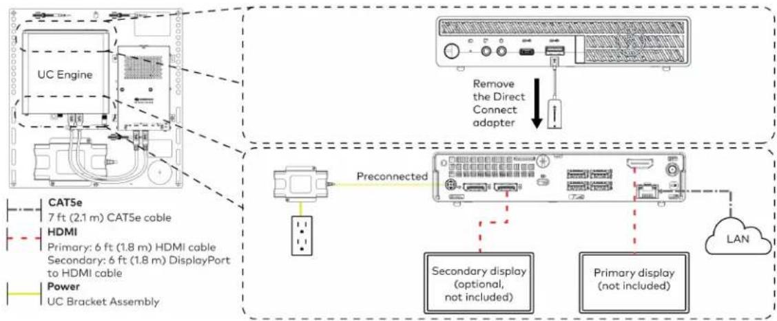
flowchart
graph TD
    A["UC Engine"] -->|CAT5e 7 ft (2.1 m) CAT5e cable| B["Preconnected"]
    A -->|HDMI Primary: 6 ft (1.8 m) HDMI cable| C["Secondary display (optional, not included)"]
    A -->|Power UC Bracket Assembly| D["Primary display (not included)"]
    A --> E["Remove the Direct Connect adapter"]
    E --> F["LAN"]
    B --> G["Secondary display (optional, not included)"]
    C --> H["Primary display (not included)"]
- Connect the power supply and camera to the bottom of the content ingest device (HD-CONV-USB-260). Connect the power supply to an AC power outlet.
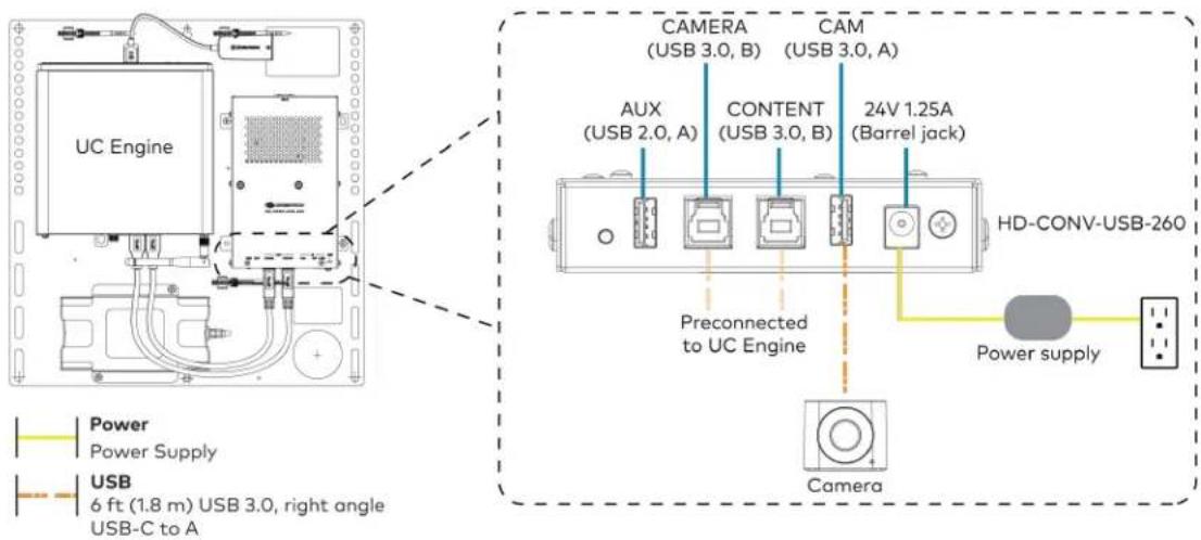
text_image
UC Engine CAMERA (USB 3.0, B) CAM (USB 3.0, A) AUX (USB 2.0, A) CONTENT (USB 3.0, B) 24V 1.25A (Barrel jack) Preconnected to UC Engine HD-CONV-USB-260 Power supply Camera Power Supply USB 6 ft (1.8 m) USB 3.0, right angle USB-C to A- Connect power and the content ingest device (HD-CONV-USB-260) to the top of the UC Presentation Transmitter. Connect the UC Engine or LAN to make a direct or network connection as described in step 1.
NOTE: If a longer cable between the UC Presentation Transmitter and the HD-CONV-USB-260 is needed, use a DigitalMedia™ Ultra cable only. The maximum supported cable length is 300 ft (91.4 m).

text_image
CAT6a 20 ft (6.1 m) CAT6a patch cable (x2) Power UC Presentation Transmitter LAN (network connection) or UC Engine (direct connection) UC Presentation Transmitter TD-R3 34V max 8.0A PWB LUN G HD-CONV-USB-260- Connect the conference device using the included PoE+ injector and USB A to Micro-B cable to the bottom of the UC Presentation Transmitter.

text_image
For firmware loading UC Presentation Transmitter PoE+ PSE 300 MAX ACC USB A PoE+ Injector Conference device CAT5e 11.8 ft (3.6 m) CAT5e cable (x2) Power PoE+ Injector USB 5.8 ft (1.8 m) USB A - Micro B cable- Connect a laptop to either the USB port or both the HDMI and USB B ports on the bottom of the UC Presentation Transmitter. Select a connection type based on the available ports on the user's laptop.
NOTES:
- If the USB port is used along with either the HDMI or USB B port, the UC Presentation Transmitter will communicate via the USB port by default.
- When connecting a laptop for BYOD presentation, select the audio source on the connected laptop.

text_image
HDMI 6.56 ft (2 m) HDMI cable (for BYOD functionality) USB 6.56 ft (2 m) USB A - Micro B cable 6.56 ft (2 m) USB cable (both for BYOD functionality) UC Presentation Transmitter or Laptop (not included) UC Presentation Transmitter USB USB HDMI IN Laptop (not included)- Bundle the cables to the bracket assembly with the integrated cable tie wraps. The cable tie wraps are reusable.
Apply Power
Press the power button on the bottom of the UC Engine and apply power to all of the other devices in the system.
Configure the Conference Device
- On a computer, enter the IP address found in the conference device's settings into a web browser.
NOTES:
- The device and computer must be on the same network switch and VLAN.
-
A login with administrative rights for the device is required.
-
Log in to the device and navigate to DEVICE > Applications.
- Enter the following information in the appropriate fields:
- Teams Video PC Address: Enter the IP address or hostname of the UC Engine.
NOTE: The hostname is printed on a label affixed to the UC Engine.
- Teams Video PC Port: By default, port number 49500 is used. If a different port number h been configured on the UC Engine, enter that port number instead.
- Teams Video Username: Enter the login username for the UC Engine. (The default username is "admin".)
- Teams Video Password: Enter the login password for the UC Engine. (The default password is "sfb".)
4. Select Save Changes.
Configure the System
Use the conference device and your Microsoft Teams credentials to configure the UC Engine, as described in Configuration on page 222. For detailed information on deploying Microsoft Teams Rooms, refer to the Microsoft Teams Rooms documentation.
NOTE: Microsoft Teams does not support emergency calling in Japan. For more information on emergency calling from Microsoft Teams, refer to Manage emergency calling.
Factory Reset
A factory reset may be performed when troubleshooting the conference device.
To perform a factory reset on the conference device:
-
Power cycle the device by disconnecting and reconnecting the CAT5e cable from the conference device.
-
When the device powers on and the LEDs flash green, tap the button below the Crestron® logo 10 times. A factory reset confirmation screen appears.
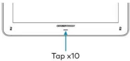
text_image
Tap x10- Tap one of the mute buttons to move the selector on the factory reset confirmation screen to Yes. Tap the button below the Crestron logo to confirm the factory reset.
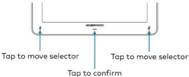
text_image
Tap to move selector Tap to confirm Tap to move selector- The device will reboot.
UC-M50-T Connections
Minimum Requirements
Ensure that the below requirements are met prior to setting up the system.
- A video display (not included) connected to the UC Engine. A second display is optional.
• A Microsoft Teams Rooms provisioned account (not included).
Install the Cable Retention Plate
The included cable retention plate provides tie-down points for cables that connect to the Crestron® conference device.
Remove the adhesive backing from the cable retention plate and install the plate on the underside of the conference device as shown in the following diagram. Ensure the cable retention plate is firmly attached before securing cables.
CAUTION: When turning over the device, place the device on a soft surface to avoid damage.
NOTE: If a swivel mount kit (CCS-UCA-SMK) is to be used, use the cable retention bracket included with the swivel mount kit as described in the CCS-UCA-SMK DO Guide (Doc. 7882).

text_image
Install cable retention plate here Cable retention plate installedIdentify the UC Bracket Assembly
The UC Bracket Assembly is available in two models. Identify the model included with your Crestron Flex system. Tap or click the corresponding image below to navigate to the appropriate connection instructions.
UC Bracket Assembly with HD-CONV-USB-200 UC Bracket Assembly with HD-CONV-USB-300
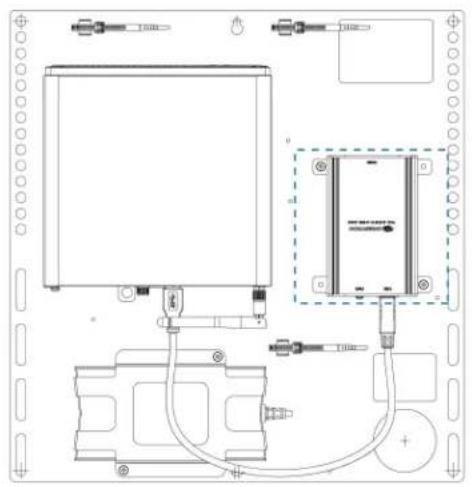
natural_image
Technical line drawing of a mechanical or electrical assembly with components and wiring (no text or symbols)
text_image
Technical schematic diagram of a device with labeled components and wiring connectionsSystem Overview
For UC Bracket Assembly with HD-CONV-USB-200
When connections are complete, the system appears as shown below. Refer to Make Connections on page 171 for detailed connection instructions.

flowchart
graph TD
    subgraph Direct Connection
        A["Secondary display (optional, not included)"]
        B["Primary display (not included)"]
        C["Laptop (not included)"]
        D["Camera"]
        E["Conference Device"]
    end

    subgraph Network Connection
        F["Secondary display (optional, not included)"]
        G["Primary display (not included)"]
        H["Laptop (not included)"]
        I["Camera"]
        J["Conference Device"]
    end

    style Direct Connection fill:#f9f9f9,stroke:#333
    style Network Connection fill:#f9f9f9,stroke:#333
For UC Bracket Assembly with HD-CONV-USB-300
When connections are complete, the system appears as shown below. Refer to Make Connections on page 171 for detailed connection instructions.
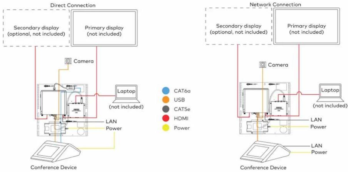
flowchart
graph TD
    subgraph Direct Connection
        A["Secondary display (optional, not included)"]
        B["Primary display (not included)"]
        C["Laptop (not included)"]
        D["Camera"]
        E["Conference Device"]
    end

    subgraph Network Connection
        F["Secondary display (optional, not included)"]
        G["Primary display (not included)"]
        H["Laptop (not included)"]
        I["Camera"]
        J["Conference Device"]
    end

    A --> D
    B --> D
    C --> D
    D --> E
    E --> F
    F --> G
    G --> H
    H --> I
    style A fill:#f9f,stroke:#333
    style B fill:#f9f,stroke:#333
    style C fill:#ccf,stroke:#333
    style D fill:#cfc,stroke:#333
    style E fill:#fcc,stroke:#333
    style F fill:#cff,stroke:#333
    style G fill:#ffc,stroke:#333
    style H fill:#fcc,stroke:#333
    style I fill:#cff,stroke:#333
Make Connections
NOTE: For reference, the UC Bracket Assembly is shown with the HD-CONV-USB-200 in the following connection diagrams. Unless otherwise indicated in this guide, the connections remain the same for the UC Bracket Assembly with HD-CONV-USB-200 and HD-CONV-USB-300.
- Make UC Engine connections as shown in the following illustrations. The conference device can communicate with the UC Engine over a direct connection or a network connection. Select one of the connection types as described below.
- Make a direct connection for simple installation and setup. Only use the direct connect adapter to connect the conference device to the UC Engine. Do not use the direct connect adapter to connect the UC Engine to the network.
Direct Connection
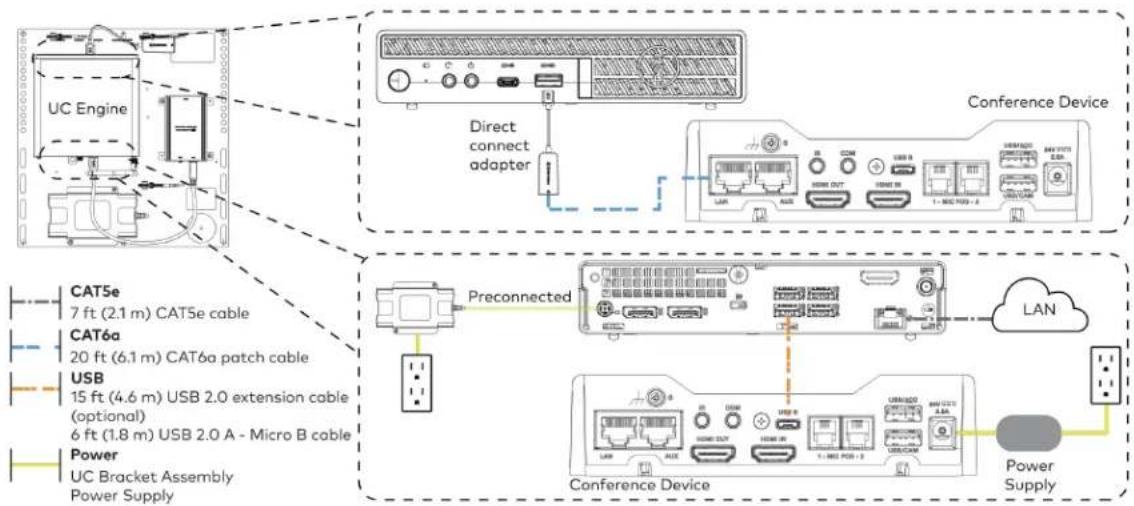
flowchart
graph TD
    A["UC Engine"] --> B["Direct connect adapter"]
    B --> C["Conference Device"]
    C --> D["Preconnected"]
    D --> E["Conference Device"]
    E --> F["Power Supply"]
    subgraph CAT5e
        G["7 ft (2.1 m) CAT5e cable"]
    end
    subgraph CAT6a
        H["20 ft (6.1 m) CAT6a patch cable"]
    end
    subgraph USB
        I["15 ft (4.6 m) USB 2.0 extension cable (optional)"]
        J["6 ft (1.8 m) USB 2.0 A - Micro B cable"]
    end
    subgraph Power
        K["UC Bracket Assembly Power Supply"]
    end
    L["LAN"] --> M["Cloud"]
    M --> N["Power Supply"]
    style A fill:#f9f,stroke:#333
    style B fill:#ccf,stroke:#333
    style C fill:#cfc,stroke:#333
    style D fill:#fcc,stroke:#333
    style E fill:#cff,stroke:#333
    style F fill:#ffc,stroke:#333
    style G fill:#fff,stroke:#333
    style H fill:#fff,stroke:#333
    style I fill:#fff,stroke:#333
    style J fill:#fff,stroke:#333
    style K fill:#fff,stroke:#333
    style L fill:#fff,stroke:#333
    style M fill:#fff,stroke:#333
- Make a network connection if the system is to be managed by the XiO Cloud® service.
NOTE: When a network connection is used, disconnect the direct connect adapter from the UC Engine.
Network Connection
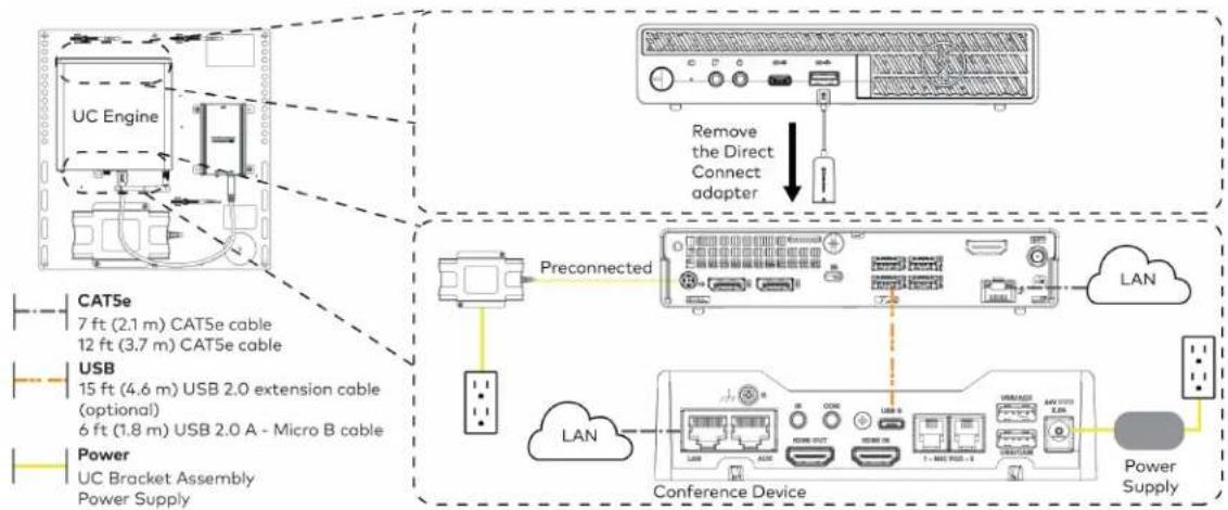
flowchart
graph TD
    A["UC Engine"] -->|Preconnected| B["Conference Device"]
    B --> C["Power Supply"]
    D["Remove the Direct Connect adapter"] --> B
    E["Preconnected"] --> F["LAN"]
    G["Conference Device"] --> H["Power Supply"]
    I["Preconnected"] --> J["LAN"]
    K["Preconnected"] --> L["LAN"]
    M["Preconnected"] --> N["LAN"]
    O["Preconnected"] --> P["LAN"]
    Q["Preconnected"] --> R["LAN"]
    S["Preconnected"] --> T["LAN"]
    U["Preconnected"] --> V["LAN"]
    W["Preconnected"] --> X["LAN"]
    Y["Preconnected"] --> Z["LAN"]
- Connect displays to the UC Engine.

text_image
UC Engine HDMI Primary: 6 ft (1.8 m) HDMI cable Secondary: 6 ft (1.8 m) DisplayPort to HDMI cable Secondary display (optional, not included) Primary display (not included)- Connect the camera to the UC Engine as shown in the image below. Do not connect the camera to any of the other USB ports.

text_image
UC Engine Camera HD-CONV-USB-200 or HD-CONV-USB-300 (preconnected) USB 6 ft (1.8 m) USB 3.0, right angle USB-C to A- Connect a laptop to the HD-CONV-USB-200 or HD-CONV-USB-300.
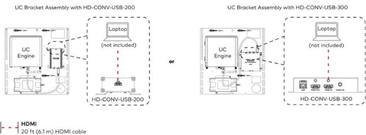
text_image
UC Bracket Assembly with HD-CONV-USB-200 Laptop (not included) HD-CONV-USB-200 or UC Bracket Assembly with HD-CONV-USB-300 Laptop (not included) HD-CONV-USB-300 HDMI 20 ft (6.1 m) HDMI cable- Bundle the cables to the bracket assembly with the integrated cable tie wraps. The cable tie wraps are reusable.
Bundle Cables
Bundle the cables together and use a provided tie wrap to secure the bundle to one of the positions on the cable retention plate at the rear of the device. Avoid bundling power and data cables together.

text_image
Bundle cables hereApply Power
Press the power button on the bottom of the UC Engine and apply power to all of the other devices in the system. The conference device will display its IP address.
Configure the Conference Device
NOTE: If a Direct Connection was made between the conference device and the UC Engine, skip to Configure the System on page 175.
- On a computer, enter the IP address displayed on the conference device into a web browser.
NOTES:
• The device and computer must be on the same network switch and VLAN.
- A login with administrative rights for the device is required.
- Log in to the device and navigate to DEVICE > Applications.
- Enter the following information in the appropriate fields:
- Teams Video PC Address: Enter the IP address or hostname of the UC Engine.
NOTE: The hostname is printed on a label affixed to the UC Engine.
- Teams Video PC Port: By default, port number 49500 is used. If a different port number h been configured on the UC Engine, enter that port number instead.
- Teams Video Username: Enter the login username for the UC Engine. (The default username is "admin".)
-
Teams Video Password: Enter the login password for the UC Engine. (The default password is "sfb".)
-
Select Save Changes.
Configure the System
Use the conference device and your Microsoft Teams credentials to configure the UC Engine, as described in Configuration on page 222. For detailed information on deploying Microsoft Teams Rooms, refer to the Microsoft Teams Rooms documentation.
UC-MX50-T Connections
Minimum Requirements
Ensure that the below requirements are met prior to setting up the system.
- A video display (not included) connected to the UC Engine. A second display is optional.
• A Microsoft Teams Rooms provisioned account (not included).
System Overview
When connections are complete, the system appears as shown below. Refer to Make Connections on page 177 for detailed connection instructions.
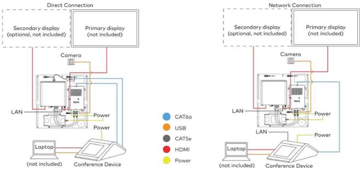
flowchart
graph TD
    subgraph Direct Connection
        A["Camera"] --> B["Primary display (not included)"]
        B --> C["Secondary display (optional, not included)"]
        C --> D["Laptop (not included)"]
        D --> E["Conference Device"]
        E --> F["Power"]
        F --> G["LAN"]
    end

    subgraph Network Connection
        H["Camera"] --> I["Primary display (not included)"]
        I --> J["Secondary display (optional, not included)"]
        J --> K["Network Connection"]
        K --> L["LAN"]
        L --> M["Conference Device"]
        M --> N["Laptop (not included)"]
        N --> O["Conference Device"]
        O --> P["Power"]
        P --> Q["CAN6a"]
        P --> R["USB"]
        P --> S["CAT5e"]
        P --> T["HDMI"]
        P --> U["Power"]
    end
Make Connections
- Make UC Engine connections as shown in the following illustrations. The conference device can communicate with the UC Engine over a direct connection or a network connection. Select one of the connection types as described below.
- Make a direct connection for simple installation and setup. Only use the direct connect adapter to connect the conference device to the UC Engine. Do not use the direct connect adapter to connect the UC Engine to the network.
Direct Connection

flowchart
graph TD
    A["UC Engine"] --> B["Direct connect adapter"]
    B --> C["Conference Device"]
    D["Preconnected"] --> E["Secondary display (optional, not included)"]
    D --> F["Primary display (not included)"]
    G["Power Supply"] --> H["HDMI Primary: 6 ft (1.8 m) HDMI cable Secondary: 6 ft (1.8 m) DisplayPort to HDMI cable"]
    I["CAT5e 7 ft (2.1 m) CAT5e cable"] --> J["CA76a 20 ft (6.1 m) CAT6a patch cable"]
- Make a network connection if the system is to be managed by the XiO Cloud® service.
NOTE: When a network connection is used, disconnect the direct connect adapter from the UC Engine.
Network Connection

flowchart
graph TD
    A["UC Engine"] -->|Preconnected| B["Preconnected Cable"]
    B --> C["LAN"]
    D["Remove the Direct Connect adapter"] -->|Remove the Direct Connect adapter| E["Device with LCD panel"]
    F["CAT5e 7 ft (2.1 m) CAT5e cable"] --> G["Central PC"]
    H["HDMI Primary: 6 ft (1.8 m) HDMI cable Secondary: 6 ft (1.8 m) DisplayPort to HDMI cable Power Power supply"] --> I["Central PC"]
    J["Secondary display (optional, not included)"] --> K["Central PC"]
    L["Primary display (not included)"] --> M["Central PC"]
- Make a network or direct connection on the bottom of the conference device as described in step 1. Make the remaining content ingest, laptop, and power connections. Connect the conference device's power supply to an AC power outlet.
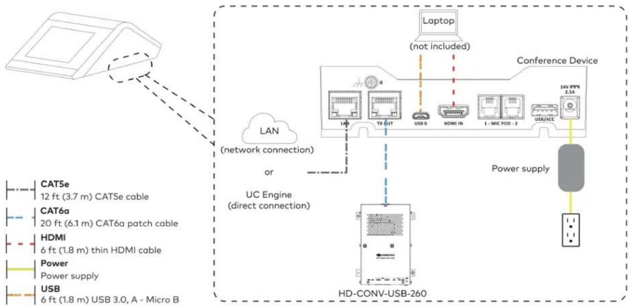
flowchart
graph TD
    A["Camera"] --> B["LAN (network connection)"]
    B --> C["UC Engine (direct connection)"]
    C --> D["HD-CONV-USB-260"]
    D --> E["Laptop (not included)"]
    E --> F["Conference Device"]
    F --> G["Power supply"]
    G --> H["HD-CONV-USB-260"]
    style A fill:#f9f,stroke:#333
    style B fill:#ccf,stroke:#333
    style C fill:#cfc,stroke:#333
    style D fill:#fcc,stroke:#333
    style E fill:#ffc,stroke:#333
    style F fill:#cff,stroke:#333
    style G fill:#ffc,stroke:#333
    style H fill:#fcc,stroke:#333
- Connect the power supply and camera to the bottom of the content ingest device (HD-CONV-USB-260). Connect the power supply to an AC power outlet.

text_image
UC Engine CAMERA (USB 3.0, B) CAM (USB 3.0, A) AUX (USB 2.0, A) CONTENT (USB 3.0, B) 24V 1.25A (Barrel jack) Preconnected to UC Engine HD-CONV-USB-260 Power supply Camera Power Supply USB 6 ft (1.8 m) USB 3.0, right angle USB-C to A- Bundle the cables to the bracket assembly with the integrated cable tie wraps. The cable tie wraps are reusable.
Apply Power
Press the power button on the bottom of the UC Engine and apply power to all of the other devices in the system.
Configure the Conference Device
- On a computer, enter the IP address displayed on the conference device into a web browser to configure the device to operate in Teams Video mode.
NOTES:
• The device and computer must be on the same network switch and VLAN.
- A login with administrative rights for the device is required.
-
Log in to the device and navigate to DEVICE > Applications.
-
Enter the following information in the appropriate fields:
- Teams Video PC Address: Enter the IP address or hostname of the UC Engine.
NOTE: The hostname is printed on a label affixed to the UC Engine.
- Teams Video PC Port: By default, port number 49500 is used. If a different port number h been configured on the UC Engine, enter that port number instead.
- Teams Video Username: Enter the login username for the UC Engine. (The default username is "admin".)
- Teams Video Password: Enter the login password for the UC Engine. (The default password is "sfb".)
4. Select Save Changes.
Configure the System
Use the conference device and your Microsoft Teams credentials to configure the UC Engine, as described in Configuration on page 222. For detailed information on deploying Microsoft Teams Rooms, refer to the Microsoft Teams Rooms documentation.
UC-M50-T-UPGRD Connections
Minimum Requirements
Ensure that the below requirements are met prior to setting up the system.
- A Crestron Flex tabletop conference device and camera.
- A video display (not included) connected to the UC Engine. A second display is optional.
- A Microsoft Teams Rooms provisioned account (not included).
Configure the Conference Device
Prior to making system connections, deployed conference devices must be configured to operate as part of a complete Microsoft Teams system. Some deployed conference devices may be operating in Crestron Default mode.
To configure the conference device to operate in Microsoft Teams mode:
- On a computer, enter the IP address displayed on the conference device into a web browser.
NOTES:
- The device and computer must be on the same network switch and VLAN.
-
A login with administrative rights for the device is required.
-
Log in to the device and navigate to DEVICE > Applications.
- From the Application Mode drop down menu, select Teams Video.
- Select Save Changes. The conference device will reboot in Microsoft Teams mode and log out all users.
- Download the latest CCS-UC-1-T-V firmware from www.crestron.com/firmware.
- Log in to the device and navigate to DEVICE > Device Management.
- In the Firmware section, select Firmware Upgrade. Upload the firmware downloaded in step 5. When the firmware upload is complete, the device will reboot and log out all users.
- Log in to the device and navigate to DEVICE > Device Management.
- In the Maintenance section, select Restore to reset the device to the factory default settings.
Identify the UC Bracket Assembly
The UC Bracket Assembly is available in two models. Identify the model included with your Crestron Flex system. Tap or click the corresponding image below to navigate to the appropriate connection instructions.
UC Bracket Assembly with HD-CONV-USB-200 UC Bracket Assembly with HD-CONV-USB-300

natural_image
Technical line drawing of an electrical enclosure with wiring and components (no text or symbols)
text_image
Technical schematic diagram of a device with labeled components and wiring connectionsSystem Overview
For UC Bracket Assembly with HD-CONV-USB-200
When connections are complete, the system appears as shown below. Refer to Make Connections on page 183 for detailed connection instructions.
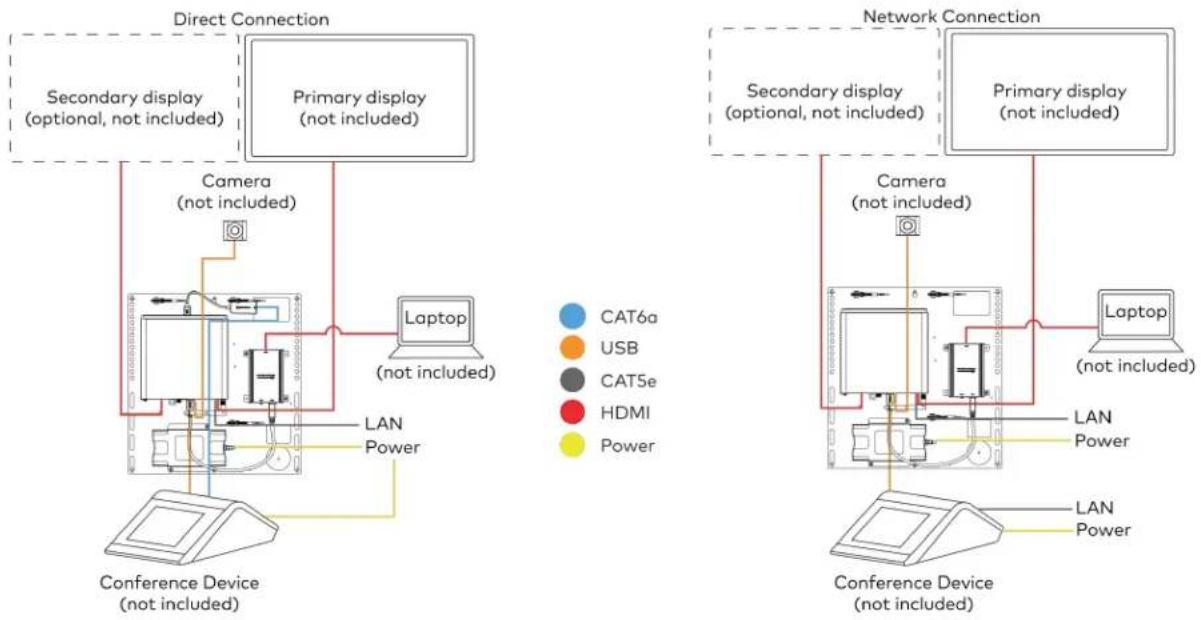
flowchart
graph TD
    subgraph Direct Connection
        A["Secondary display (optional, not included)"]
        B["Primary display (not included)"]
        C["Camera (not included)"]
        D["Laptop (not included)"]
        E["Conference Device (not included)"]
    end

    subgraph Network Connection
        F["Secondary display (optional, not included)"]
        G["Primary display (not included)"]
        H["Laptop (not included)"]
        I["Conference Device (not included)"]
    end

    A --> J["Camera (not included)"]
    B --> K["Laptop (not included)"]
    C --> L["Conference Device (not included)"]
    D --> M["Laptop (not included)"]
    E --> N["Laptop (not included)"]
    F --> O["Camera (not included)"]
    G --> P["Laptop (not included)"]
    H --> Q["Laptop (not included)"]
    I --> R["Laptop (not included)"]
    J --> S["Power"]
    K --> T["Power"]
    L --> U["Power"]
    M --> V["Power"]
    N --> W["Power"]
    O --> X["Power"]
    P --> Y["Power"]
    Q --> Z["Power"]
    R --> AA["Power"]
    S --> AB["Power"]
    T --> AC["Power"]
    U --> AD["Power"]
    V --> AE["Power"]
    W --> AF["Power"]
    X --> AG["Power"]
    Y --> AH["Power"]
    Z --> AI["Power"]
For UC Bracket Assembly with HD-CONV-USB-300
When connections are complete, the system appears as shown below. Refer to Make Connections on page 183 for detailed connection instructions.
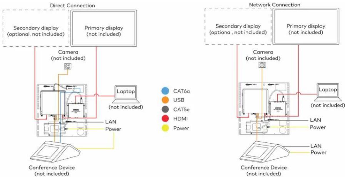
flowchart
graph TD
    subgraph Direct Connection
        A["Secondary display (optional, not included)"]
        B["Primary display (not included)"]
        C["Camera (not included)"]
        D["Laptop (not included)"]
        E["Conference Device (not included)"]
    end

    subgraph Network Connection
        F["Secondary display (optional, not included)"]
        G["Primary display (not included)"]
        H["Laptop (not included)"]
        I["Conference Device (not included)"]
    end

    A --> J["Camera (not included)"]
    B --> K["Laptop (not included)"]
    C --> L["Conference Device (not included)"]
    D --> M["Laptop (not included)"]
    E --> N["Laptop (not included)"]
    F --> O["Camera (not included)"]
    G --> P["Laptop (not included)"]
    H --> Q["Laptop (not included)"]
    I --> R["Laptop (not included)"]
    J --> S["Power"]
    K --> T["Power"]
    L --> U["Power"]
    M --> V["Power"]
    N --> W["Power"]
    O --> X["Power"]
    P --> Y["Power"]
    Q --> Z["Power"]
    R --> AA["Power"]
    S --> AB["Power"]
    T --> AC["Power"]
    U --> AD["Power"]
    V --> AE["Power"]
    W --> AF["Power"]
    X --> AG["Power"]
    Y --> AH["Power"]
    Z --> AI["Power"]
Make Connections
NOTE: For reference, the UC Bracket Assembly is shown with the HD-CONV-USB-200 in the following connection diagrams. Unless otherwise indicated in this guide, the connections remain the same for the UC Bracket Assembly with HD-CONV-USB-200 and HD-CONV-USB-300.
- Make UC Engine connections as shown in the following illustrations. The conference device can communicate with the UC Engine over a direct connection or a network connection. Select one of the connection types as described below.
- Make a direct connection for simple installation and setup. Only use the direct connect adapter to connect the conference device to the UC Engine. Do not use the direct connect adapter to connect the UC Engine to the network.
Direct Connection

flowchart
graph TD
    A["UC Engine"] --> B["Direct connect adapter"]
    B --> C["Conference Device"]
    C --> D["Preconnected"]
    D --> E["Conference Device"]
    E --> F["Power Supply"]
    subgraph CAT5e
        G["7 ft (2.1 m) CAT5e cable"]
    end
    subgraph CAT6a
        H["20 ft (6.1 m) CAT6a patch cable"]
    end
    subgraph USB
        I["15 ft (4.6 m) USB 2.0 extension cable (optional)"]
        J["6 ft (1.8 m) USB 2.0 A - Micro B cable"]
    end
    subgraph Power
        K["UC Bracket Assembly Power Supply"]
    end
    L["LAN"] --> M["Cloud"]
    M --> N["Power Supply"]
    style A fill:#f9f,stroke:#333
    style B fill:#ccf,stroke:#333
    style C fill:#cfc,stroke:#333
    style D fill:#fcc,stroke:#333
    style E fill:#cff,stroke:#333
    style F fill:#ffc,stroke:#333
    style G fill:#fff,stroke:#333
    style H fill:#fff,stroke:#333
    style I fill:#fff,stroke:#333
    style J fill:#fff,stroke:#333
    style K fill:#fff,stroke:#333
    style L fill:#fff,stroke:#333
    style M fill:#fff,stroke:#333
- Make a network connection if the system is to be managed by the XiO Cloud® service.
NOTE: When a network connection is used, disconnect the direct connect adapter from the UC Engine.
Network Connection
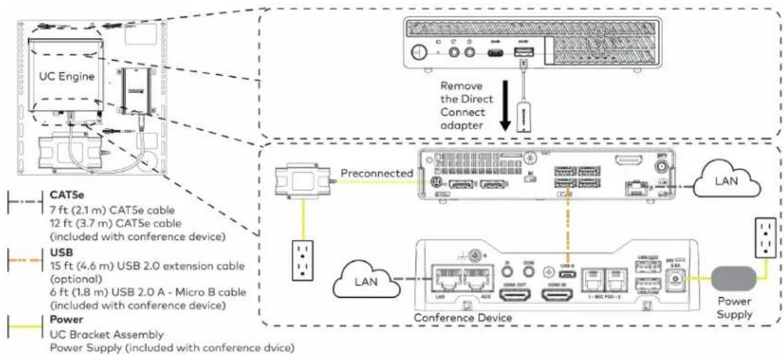
flowchart
graph TD
    A["UC Engine"] -->|Preconnected| B["Conference Device"]
    C["USB"] -->|Preconnected| B
    D["Power"] -->|Preconnected| B
    B --> E["LAN"]
    B --> F["Conference Device"]
    F --> G["Power Supply"]
    H["Remove the Direct Connect adapter"] --> I["Device with Connection Adapter"]
    style A fill:#f9f,stroke:#333
    style C fill:#f9f,stroke:#333
    style D fill:#f9f,stroke:#333
    style H fill:#ccf,stroke:#333
    style I fill:#ccf,stroke:#333
- Connect displays to the UC Engine.
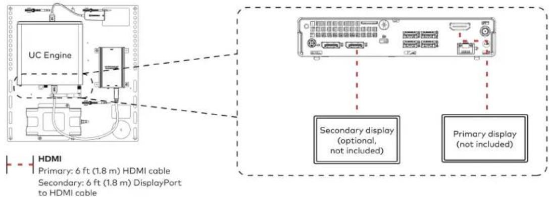
text_image
UC Engine HDMI Primary: 6 ft (1.8 m) HDMI cable Secondary: 6 ft (1.8 m) DisplayPort to HDMI cable Secondary display (optional, not included) Primary display (not included)- Connect a camera (not included) to the UC Engine as shown in the image below. Do not connect the camera to any of the other USB ports.
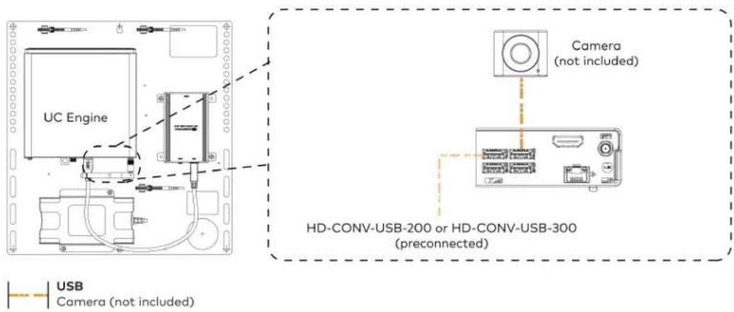
text_image
UC Engine Camera (not included) HD-CONV-USB-200 or HD-CONV-USB-300 (preconnected) USB Camera (not included)- Connect a laptop to the HD-CONV-USB-200 or HD-CONV-USB-300.

text_image
UC Bracket Assembly with HD-CONV-USB-200 Laptop (not included) HD-CONV-USB-200 or UC Bracket Assembly with HD-CONV-USB-300 Laptop (not included) HD-CONV-USB-300 HDMI 20 ft (6.1 m) HDMI cable- Bundle the cables to the bracket assembly with the integrated cable tie wraps. The cable tie wraps are reusable.
Bundle Cables
Bundle the cables together and use a provided tie wrap to secure the bundle to one of the positions on the cable retention plate at the rear of the device. Avoid bundling power and data cables together.

text_image
Bundle cables hereApply Power
Press the power button on the bottom of the UC Engine and apply power to all of the other devices in the system. The conference device will display its IP address.
Complete the Conference Device Configuration
NOTE: If a Direct Connection was made between the conference device and the UC Engine, skip to Configure the System on page 187.
- On a computer, enter the IP address displayed on the conference device into a web browser.
NOTES:
• The device and computer must be on the same network switch and VLAN.
- A login with administrative rights for the device is required.
-
Log in to the device and navigate to DEVICE > Applications.
-
Enter the following information in the appropriate fields:
- Teams Video PC Address: Enter the IP address or hostname of the UC Engine.
NOTE: The hostname is printed on a label affixed to the UC Engine.
- Teams Video PC Port: By default, port number 49500 is used. If a different port number h been configured on the UC Engine, enter that port number instead.
- Teams Video Username: Enter the login username for the UC Engine. (The default username is "admin".)
-
Teams Video Password: Enter the login password for the UC Engine. (The default password is "sfb".)
-
Select Save Changes.
Configure the System
Use the conference device and your Microsoft Teams credentials to configure the UC Engine, as described in Configuration on page 222. For detailed information on deploying Microsoft Teams Rooms, refer to the Microsoft Teams Rooms documentation.
UC-MX50-T-UPGRD Connections
Minimum Requirements
Ensure that the below requirements are met prior to setting up the system.
- A Crestron Flex tabletop conference device and camera.
- A video display (not included) connected to the UC Engine. A second display is optional.
- A Microsoft Teams Rooms provisioned account (not included).
Configure the Conference Device
Prior to making system connections, deployed conference devices must be configured to operate as part of a complete Microsoft Teams system. Some deployed conference devices may be operating in Crestron Default mode.
To configure the conference device to operate in Microsoft Teams mode:
- On a computer, enter the IP address displayed on the conference device into a web browser.
NOTES:
- The device and computer must be on the same network switch and VLAN.
-
A login with administrative rights for the device is required.
-
Log in to the device and navigate to DEVICE > Applications.
- From the Application Mode drop down menu, select Teams Video.
- Select Save Changes. The conference device will reboot in Microsoft Teams mode and log out all users.
- Download the latest CCS-UC-1-T-V firmware from www.crestron.com/firmware.
- Log in to the device and navigate to DEVICE > Device Management.
- In the Firmware section, select Firmware Upgrade. Upload the firmware downloaded in step 5. When the firmware upload is complete, the device will reboot and log out all users.
- Log in to the device and navigate to DEVICE > Device Management.
- In the Maintenance section, select Restore to reset the device to the factory default settings.
System Overview
When connections are complete, the system appears as shown below. Refer to Make Connections on page 189 for detailed connection instructions.

Make Connections
- Make UC Engine connections as shown in the following illustrations. The conference device can communicate with the UC Engine over a direct connection or a network connection. Select one of the connection types as described below.
- Make a direct connection for simple installation and setup. Only use the direct connect adapter to connect the conference device to the UC Engine. Do not use the direct connect adapter to connect the UC Engine to the network.
Direct Connection
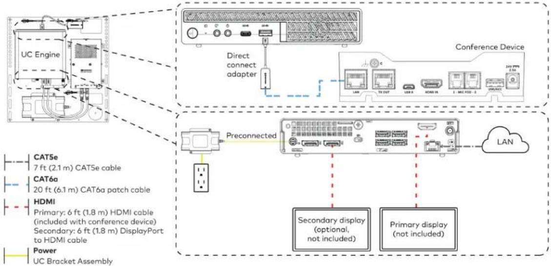
flowchart
graph TD
    A["UC Engine"] --> B["Direct connect adapter"]
    B --> C["Conference Device"]
    C --> D["Preconnected"]
    D --> E["Secondary display (optional, not included)"]
    D --> F["Primary display (not included)"]
- Make a network connection if the system is to be managed by the XiO Cloud® service.
NOTE: When a network connection is used, disconnect the direct connect adapter from the UC Engine.
Network Connection

flowchart
graph TD
    A["UC Engine"] -->|Remove the Direct Connect adapter| B["Preconnected"]
    C["CAT5e 7 ft (2.1 m) CAT5e cable"] -->|Preconnected| D["LAN"]
    E["HDMI Primary: 6 ft (1.8 m) HDMI cable (included with conference device)<br>Secondary: 6 ft (1.8 m) DisplayPort to HDMI cable"] --> F["Preconnected"]
    G["Power UC Bracket Assembly"] --> H["Preconnected"]
    I["Secondary display (optional, not included)"] --> J["LAN"]
    K["Primary display (not included)"] --> J
- Connect the power supply and camera to the bottom of the content ingest device (HD-CONV-USB-260). Connect the power supply to an AC power outlet.
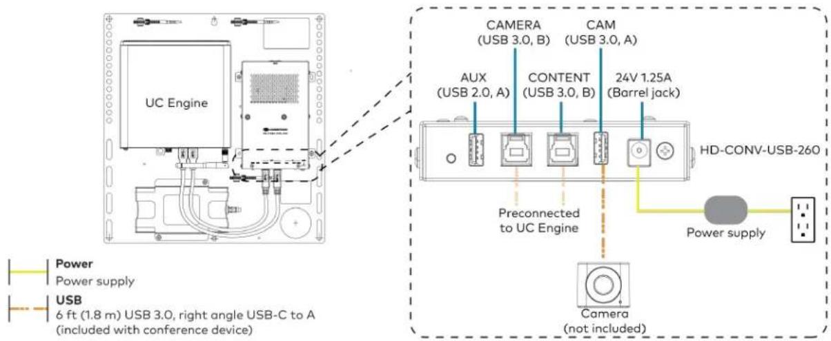
text_image
UC Engine CAMERA (USB 3.0, B) CAM (USB 3.0, A) AUX (USB 2.0, A) CONTENT (USB 3.0, B) 24V 1.25A (Barrel jack) Preconnected to UC Engine HD-CONV-USB-260 Power supply USB 6 ft (1.8 m) USB 3.0, right angle USB-C to A (included with conference device) Camera (not included)- Make a network or direct connection on the bottom of the conference device as described in step 1. Make the remaining content ingest, laptop, and power connections. Connect the conference device's power supply to an AC power outlet.

flowchart
graph TD
    A["Camera"] -->|LAN (network connection)| B["UC Engine (direct connection)"]
    B --> C["HD-CONV-USB-260"]
    C --> D["Laptop (not included)"]
    C --> E["Conference Device (not included)"]
    D --> F["LAN"]
    D --> G["TX OUT"]
    D --> H["USB B"]
    D --> I["HDMI IN"]
    D --> J["1 - MIC POD - 2"]
    D --> K["USB/ACC"]
    E --> L["24V PPS 2.5A"]
    C --> M["Power supply (not included)"]
    M --> N["Ground"]
    style A fill:#f9f,stroke:#333
    style B fill:#ccf,stroke:#333
    style C fill:#cfc,stroke:#333
    style D fill:#fcc,stroke:#333
    style E fill:#cff,stroke:#333
    style F fill:#ffc,stroke:#333
    style G fill:#ffc,stroke:#333
    style H fill:#ffc,stroke:#333
    style I fill:#ffc,stroke:#333
    style J fill:#ffc,stroke:#333
    style K fill:#ffc,stroke:#333
    style L fill:#ffc,stroke:#333
    style M fill:#ffc,stroke:#333
(All cables are included with the conference device)
- Bundle the cables to the bracket assembly with the integrated cable tie wraps. The cable tie wraps are reusable.
Bundle Cables
Bundle the cables together and use a provided tie wrap to secure the bundle to one of the positions on the cable retention plate at the rear of the device. Avoid bundling power and data cables together.

text_image
Bundle cables hereApply Power
Press the power button on the bottom of the UC Engine and apply power to all of the other devices in the system.
Complete the Conference Device Configuration
NOTE: If a Direct Connection was made between the conference device and the UC Engine, skip to Configure the System on page 193.
- On a computer, enter the IP address displayed on the conference device into a web browser.
NOTES:
- The device and computer must be on the same network switch and VLAN.
-
A login with administrative rights for the device is required.
-
Log in to the device and navigate to DEVICE > Applications.
-
Enter the following information in the appropriate fields:
- Teams Video PC Address: Enter the IP address or hostname of the UC Engine.
NOTE: The hostname is printed on a label affixed to the UC Engine.
- Teams Video PC Port: By default, port number 49500 is used. If a different port number h been configured on the UC Engine, enter that port number instead.
- Teams Video Username: Enter the login username for the UC Engine. (The default username is "admin".)
- Teams Video Password: Enter the login password for the UC Engine. (The default password is "sfb".)
4. Select Save Changes.
Configure the System
Use the conference device and your Microsoft Teams credentials to configure the UC Engine, as described in Configuration on page 222. For detailed information on deploying Microsoft Teams Rooms, refer to the Microsoft Teams Rooms documentation.
UC-M70-T Connections
Minimum Requirements
Ensure that the below requirements are met prior to setting up the system.
- A video display (not included) connected to the UC Engine. A second display is optional.
• A Microsoft Teams Rooms provisioned account (not included).
Install the Cable Retention Plate
The included cable retention plate provides tie-down points for cables that connect to the Crestron® conference device.
Remove the adhesive backing from the cable retention plate and install the plate on the underside of the conference device as shown in the following diagram. Ensure the cable retention plate is firmly attached before securing cables.
CAUTION: When turning over the device, place the device on a soft surface to avoid damage.
NOTE: If a swivel mount kit (CCS-UCA-SMK) is to be used, use the cable retention bracket included with the swivel mount kit as described in the CCS-UCA-SMK DO Guide (Doc. 7882).

text_image
Install cable retention plate here Cable retention plate installedIdentify the UC Bracket Assembly
The UC Bracket Assembly is available in two models. Identify the model included with your Crestron Flex system. Tap or click the corresponding image below to navigate to the appropriate connection instructions.
UC Bracket Assembly with HD-CONV-USB-200 UC Bracket Assembly with HD-CONV-USB-300
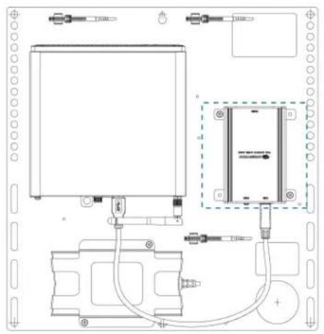
natural_image
Technical line drawing of an electronic device with components and wiring (no text or symbols)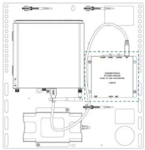
text_image
Technical schematic diagram of a device with labeled components and wiring connectionsSystem Overview
For UC Bracket Assembly with HD-CONV-USB-200
When connections are complete, the system appears as shown below. Refer to Make Connections on page 196 for detailed connection instructions.
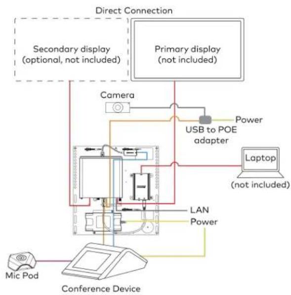
flowchart
graph TD
    A["Primary display (not included)"] --> B["Camera"]
    B --> C["USB to POE adapter"]
    C --> D["Laptop (not included)"]
    D --> E["Laptop"]
    F["Secondary display (optional, not included)"] --> G["Conference Device"]
    H["Direct Connection"] --> I["Camera"]
    I --> J["USB to POE adapter"]
    J --> K["Laptop"]
    L["Mic Pod"] --> M["Conference Device"]
    N["LAN Power"] --> O["Computer"]
    P["Power"] --> Q["USB to POE adapter"]
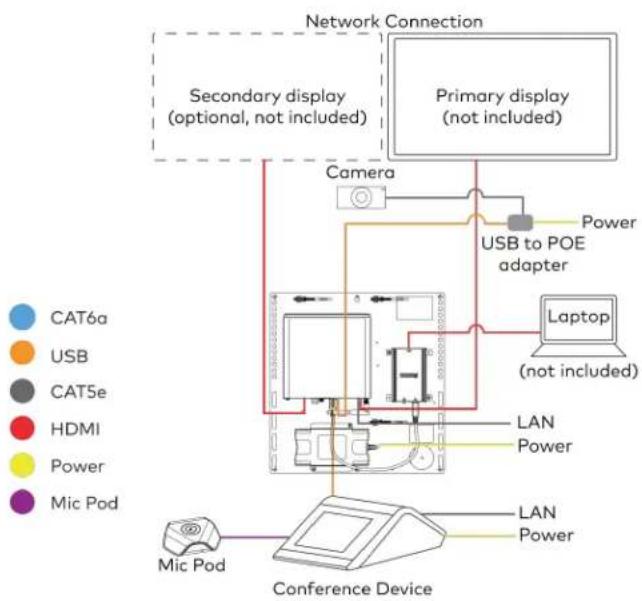
flowchart
graph TD
    A["Cat6a"] --> B["USB"]
    B --> C["CAT5e"]
    C --> D["HDMI"]
    D --> E["Power"]
    E --> F["Mic Pod"]
    F --> G["Conference Device"]
    H["Primary display (not included)"] --> I["Camera"]
    I --> J["USB to POE adapter"]
    J --> K["Laptop (not included)"]
    K --> L["LAN Power"]
    L --> M["Camfer"]
    M --> N["Network Connection"]
    O["Secondary display (optional, not included)"] --> P["Camera"]
    Q["Conference Device"] --> R["LAN Power"]
    S["Primary display (not included)"] --> T["Camera"]
    U["Primary display (not included)"] --> V["USB to POE adapter"]
    W["Primary display (not included)"] --> X["Laptop (not included)"]
For UC Bracket Assembly with HD-CONV-USB-300
When connections are complete, the system appears as shown below. Refer to Make Connections on page 196 for detailed connection instructions.

flowchart
graph TD
    subgraph Direct Connection
        A["Secondary display (optional, not included)"]
        B["Primary display (not included)"]
        C["Laptop (not included)"]
        D["Camera"] --> E["USB to POE adapter"]
        F["LAN Power"] --> G["Conference Device"]
        H["Mic Pod"] --> I["Conference Device"]
    end

    subgraph Network Connection
        J["Secondary display (optional, not included)"]
        K["Primary display (not included)"]
        L["Laptop (not included)"]
        M["Camera"] --> N["USB to POE adapter"]
        O["LAN Power"] --> P["Conference Device"]
        Q["Mic Pod"] --> R["Conference Device"]
        S["Power"] --> T["USB to POE adapter"]
        U["Water"] --> V["Network Connection"]
        W["Water"] --> X["Network Connection"]
    end

    style Direct Connection fill:#f9f,stroke:#333
    style Network Connection fill:#bbf,stroke:#333
Make Connections
NOTE: For reference, the UC Bracket Assembly is shown with the HD-CONV-USB-200 in the following connection diagrams. Unless otherwise indicated in this guide, the connections remain the same for the UC Bracket Assembly with HD-CONV-USB-200 and HD-CONV-USB-300.
- Make UC Engine connections as shown in the following illustrations. The conference device can communicate with the UC Engine over a direct connection or a network connection. Select one of the connection types as described below.
- Make a direct connection for simple installation and setup. Only use the direct connect adapter to connect the conference device to the UC Engine. Do not use the direct connect adapter to connect the UC Engine to the network.
Direct Connection

flowchart
graph TD
    A["UC Engine"] --> B["Direct connect adapter"]
    B --> C["Conference Device"]
    C --> D["Preconnected"]
    D --> E["Conference Device"]
    E --> F["Power Supply"]
    subgraph CAT5e
        G["7 ft (2.1 m) CAT5e cable"]
    end
    subgraph CAT6a
        H["20 ft (6.1 m) CAT6a patch cable"]
    end
    subgraph Microphone
        I["12 ft (3.7 m) cable"]
    end
    subgraph USB
        J["15 ft (4.6 m) USB 2.0 extension cable (optional)"]
        K["6 ft (1.8 m) USB 2.0 A - Micro B cable"]
    end
    subgraph Power
        L["UC Bracket Assembly Power Supply"]
    end
    G --> D
    H --> D
    I --> D
    J --> D
    K --> D
    L --> D
    D --> M["Preconnected"]
    M --> N["Conference Device"]
    N --> O["Power Supply"]
    style A fill:#f9f,stroke:#333
    style C fill:#ccf,stroke:#333
    style E fill:#cfc,stroke:#333
- Make a network connection if the system is to be managed by the XiO Cloud® service.
NOTE: When a network connection is used, disconnect the direct connect adapter from the UC Engine.
Network Connection

flowchart
graph TD
    A["UC Engine"] -->|Preconnected| B["Conference Device"]
    B --> C["Remove the Direct Connect adapter"]
    C --> D["LAN"]
    D --> E["Power Supply"]
    F["Preconnected"] --> G["Preconnected"]
    H["Conference Device"] --> I["LAN"]
    I --> J["Power Supply"]
    K["Preconnected"] --> L["Preconnected"]
    M["Conference Device"] --> N["Preconnected"]
    O["Preconnected"] --> P["Preconnected"]
    Q["Preconnected"] --> R["Preconnected"]
    S["Preconnected"] --> T["Preconnected"]
    U["Preconnected"] --> V["Preconnected"]
    W["Preconnected"] --> X["Preconnected"]
    Y["Preconnected"] --> Z["Preconnected"]
    AA["Preconnected"] --> AB["Preconnected"]
    AC["Preconnected"] --> AD["Preconnected"]
    AE["Preconnected"] --> AF["Preconnected"]
    AG["Preconnected"] --> AH["Preconnected"]
    AI["Preconnected"] --> AJ["Preconnected"]
    AK["Preconnected"] --> AL["Preconnected"]
    AM["Preconnected"] --> AN["Preconnected"]
    AO["Preconnected"] --> AP["Preconnected"]
    AQ["Preconnected"] --> AR["Preconnected"]
    AS["Preconnected"] --> AT["Preconnected"]
    AU["Preconnected"] --> AV["Preconnected"]
    AW["Preconnected"] --> AX["Preconnected"]
    AY["CAT5e Cable 7 ft (2.1 m) CAT5e Cable 12 ft (3.7 m) CAT5e Cable"] --> X
    AZ["USB 15 ft (4.6 m) USB 2.0 extension cable (optional) 6 ft (1.8 m) USB 2.0 A - Micro B cable"] --> X
    BA["Power UC Bracket Assembly Power Supply"] --> X
    BB["Microphone 12 ft (3.7 m) cable"] --> X
    BC["Mic Pod"] --> AD
    BD["Mic Pod"] --> AE
    BE["Mic Pod"] --> AF
    BF["Mic Pod"] --> AG
    BG["Mic Pod"] --> AH
    BH["Mic Pod"] --> AI
    AJ["Mic Pod"] --> AK
    AK --> AL
    AL --> AM
    AM --> AN
    AN --> AO
    AO --> AP
    AP --> AQ
    AQ --> AR
    AR --> AS
    AS --> AT
    AT --> AU
    AU --> AV
    AV --> AW
    AW --> AX
    AX --> AY
    AY --> AZ
    AZ --> BA
    BA --> BB
    BB --> BC
- Connect displays to the UC Engine.

text_image
UC Engine HDMI Primary: 6 ft (1.8 m) HDMI cable Secondary: 6 ft (1.8 m) DisplayPort to HDMI cable Secondary display (optional, not included) Primary display (not included)- Connect the camera to the UC Engine as shown in the image below. Do not connect the camera to any of the other USB ports.
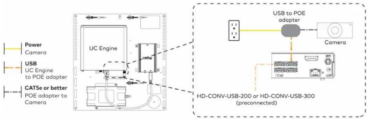
text_image
Power Camera USB UC Engine to POE adapter CAT5e or better POE adapter to Camera UC Engine HD-CONV-USB-200 or HD-CONV-USB-300 (preconnected) USB to POE adapter Camera- Connect a laptop to the HD-CONV-USB-200 or HD-CONV-USB-300.

text_image
UC Bracket Assembly with HD-CONV-USB-200 Laptop (not included) or UC Bracket Assembly with HD-CONV-USB-300 UC Engine Laptop (not included) HD-CONV-USB-300 HDMI 20 ft (6.1 m) HDMI cable- Bundle the cables to the bracket assembly with the integrated cable tie wraps. The cable tie wraps are reusable.
Bundle Cables
Bundle the cables together and use a provided tie wrap to secure the bundle to one of the positions on the cable retention plate at the rear of the device. Avoid bundling power and data cables together.
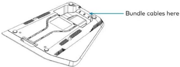
text_image
Bundle cables hereApply Power
Press the power button on the bottom of the UC Engine and apply power to all of the other devices in the system. The conference device will display its IP address.
Configure the Conference Device
NOTE: If a Direct Connection was made between the conference device and the UC Engine, skip to Configure the System on page 200.
- On a computer, enter the IP address displayed on the conference device into a web browser.
NOTES:
• The device and computer must be on the same network switch and VLAN.
- A login with administrative rights for the device is required.
-
Log in to the device and navigate to DEVICE > Applications.
-
Enter the following information in the appropriate fields:
- Teams Video PC Address: Enter the IP address or hostname of the UC Engine.
NOTE: The hostname is printed on a label affixed to the UC Engine.
- Teams Video PC Port: By default, port number 49500 is used. If a different port number h been configured on the UC Engine, enter that port number instead.
- Teams Video Username: Enter the login username for the UC Engine. (The default username is "admin".)
-
Teams Video Password: Enter the login password for the UC Engine. (The default password is "sfb".)
-
Select Save Changes.
Configure the System
Use the conference device and your Microsoft Teams credentials to configure the UC Engine, as described in Configuration on page 222. For detailed information on deploying Microsoft Teams Rooms, refer to the Microsoft Teams Rooms documentation.
UC-MX70-T Connections
Minimum Requirements
Ensure that the below requirements are met prior to setting up the system.
- A video display (not included) connected to the UC Engine. A second display is optional.
• A Microsoft Teams Rooms provisioned account (not included).
System Overview
When connections are complete, the system appears as shown below. Refer to Make Connections on page 202 for detailed connection instructions.

flowchart
graph TD
    subgraph Direct Connection
        A["Camera"] --> B["LAN"]
        C["Primary display (not included)"] --> D["Conference Device"]
        E["USB to POE adapter"] --> F["Power"]
        G["Laptop (not included)"] --> H["Conference Device"]
        I["Mic Pod"] --> J["Power"]
    end

    subgraph Network Connection
        K["Camera"] --> L["LAN"]
        M["Primary display (not included)"] --> N["Conference Device"]
        O["USB to POE adapter"] --> P["Power"]
        Q["Laptop (not included)"] --> R["Conference Device"]
        S["Mic Pod"] --> T["Power"]
    end

    style Direct Connection fill:#f9f,stroke:#333
    style Network Connection fill:#bbf,stroke:#333
Make Connections
- Make UC Engine connections as shown in the following illustrations. The conference device can communicate with the UC Engine over a direct connection or a network connection. Select one of the connection types as described below.
- Make a direct connection for simple installation and setup. Only use the direct connect adapter to connect the conference device to the UC Engine. Do not use the direct connect adapter to connect the UC Engine to the network.
Direct Connection
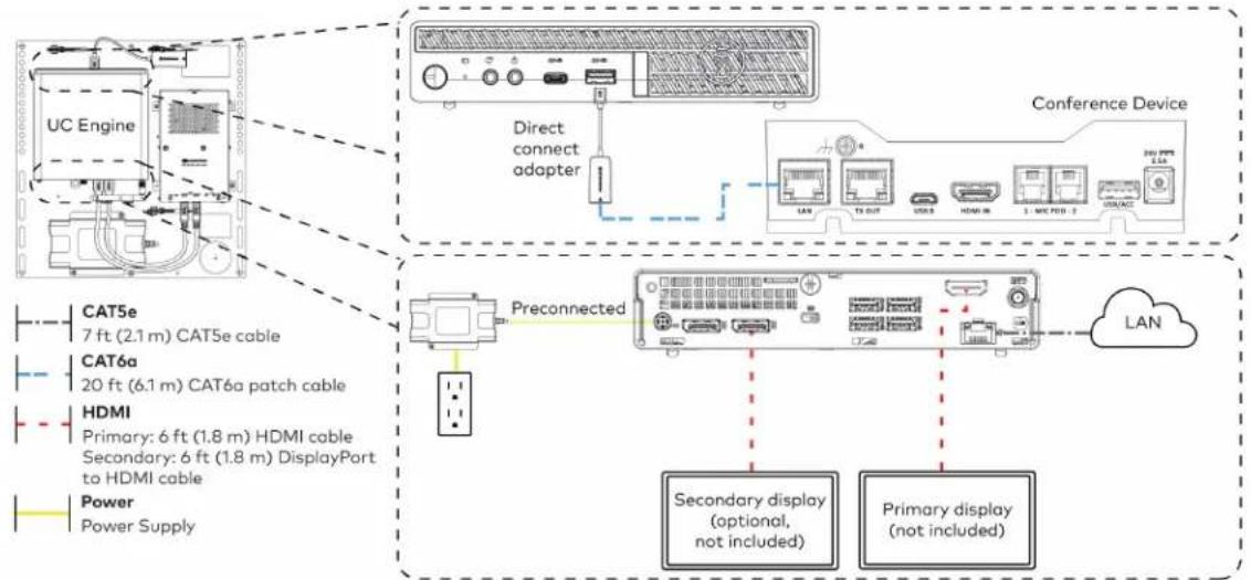
flowchart
graph TD
    A["UC Engine"] --> B["Direct connect adapter"]
    B --> C["Conference Device"]
    D["Preconnected"] --> E["Secondary display (optional, not included)"]
    D --> F["Primary display (not included)"]
    G["Power Supply"] --> H["HDMI Primary: 6 ft (1.8 m) HDMI cable Secondary: 6 ft (1.8 m) DisplayPort to HDMI cable"]
    I["CAT5e 7 ft (2.1 m) CAT5e cable"] --> J["CA76a 20 ft (6.1 m) CAT6a patch cable"]
    K["Power Supply"] --> L["Power Supply"]
    M["LAN"] --> N["TL OUT"]
    N --> O["USB"]
    O --> P["HDMI IN"]
    P --> Q["3 : MAC PORT : 2"]
    Q --> R["USBACC"]
- Make a network connection if the system is to be managed by the XiO Cloud® service.
NOTE: When a network connection is used, disconnect the direct connect adapter from the UC Engine.
Network Connection
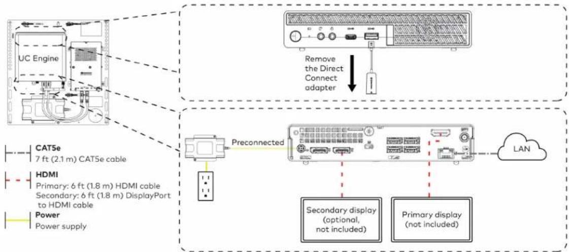
flowchart
graph TD
    A["UC Engine"] -->|Remove the Direct Connect adapter| B["Preconnected"]
    B --> C["Secondary display (optional, not included)"]
    B --> D["Primary display (not included)"]
    E["CAT5e 7 ft (2.1 m) CAT5e cable"] --> F["Preconnected"]
    G["HDMI Primary: 6 ft (1.8 m) HDMI cable Secondary: 6 ft (1.8 m) DisplayPort to HDMI cable Power Power supply"] --> H["Preconnected"]
    I["LAN"] --> J["Secondary display (optional, not included)"]
    I --> K["Primary display (not included)"]
- Make a network or direct connection on the bottom of the conference device as described in step 1. Make the remaining content ingest, laptop, mic pod, and power connections. Connect the conference device's power supply to an AC power outlet.
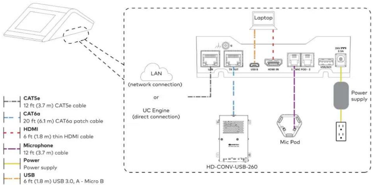
flowchart
graph TD
    A["Device"] -->|LAN (network connection)| B["UC Engine (direct connection)"]
    B --> C["HD-CONV-USB-260"]
    C --> D["Laptop"]
    C --> E["Mic Pod"]
    C --> F["Power supply"]
    B --> G["TCN"]
    B --> H["USB"]
    B --> I["USB/ACC"]
    B --> J["24V 2.5A"]
    B --> K["20 ft (6.1 m) CAT6a patch cable"]
    B --> L["6 ft (1.8 m) thin HDMI cable"]
    B --> M["20 ft (3.7 m) CAT5e cable"]
    B --> N["HDMI"]
    B --> O["Microphone"]
    B --> P["Power supply"]
    B --> Q["USB"]
    style A fill:#f9f,stroke:#333
    style B fill:#ccf,stroke:#333
    style C fill:#cfc,stroke:#333
    style D fill:#fcc,stroke:#333
    style E fill:#cff,stroke:#333
    style F fill:#ffc,stroke:#333
    style G fill:#fcc,stroke:#333
    style H fill:#fcc,stroke:#333
    style I fill:#fcc,stroke:#333
    style J fill:#fcc,stroke:#333
    style K fill:#fcc,stroke:#333
    style L fill:#fcc,stroke:#333
    style M fill:#fcc,stroke:#333
    style N fill:#fcc,stroke:#333
    style O fill:#fcc,stroke:#333
    style P fill:#fcc,stroke:#333
    style Q fill:#fcc,stroke:#333
- Connect the power supply and camera to the bottom of the content ingest device (HD-CONV-USB-260). Connect the power supplies to an AC power outlet.
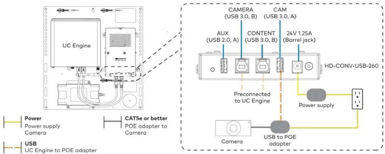
text_image
UC Engine CAT5e or better POE adapter to Camera CAMERA (USB 3.0, B) CAM (USB 3.0, A) AUX (USB 2.0, A) CONTENT (USB 3.0, B) 24V 1.25A (Barrel jack) Preconnected to UC Engine HD-CONV-USB-260 Power supply USB to POE adapter Camera USB to POE adapter Power Power supply Camera USB to POE adapter- Bundle the cables to the bracket assembly with the integrated cable tie wraps. The cable tie wraps are reusable.
Apply Power
Press the power button on the bottom of the UC Engine and apply power to all of the other devices in the system.
Configure the Conference Device
- On a computer, enter the IP address displayed on the conference device into a web browser to configure the device to operate in Teams Video mode.
NOTES:
- The device and computer must be on the same network switch and VLAN.
-
A login with administrative rights for the device is required.
-
Log in to the device and navigate to DEVICE > Applications.
-
Enter the following information in the appropriate fields:
- Teams Video PC Address: Enter the IP address or hostname of the UC Engine.
NOTE: The hostname is printed on a label affixed to the UC Engine.
- Teams Video PC Port: By default, port number 49500 is used. If a different port number h been configured on the UC Engine, enter that port number instead.
- Teams Video Username: Enter the login username for the UC Engine. (The default username is "admin".)
- Teams Video Password: Enter the login password for the UC Engine. (The default password is "sfb".)
4. Select Save Changes.
Configure the System
Use the conference device and your Microsoft Teams credentials to configure the UC Engine, as described in Configuration on page 222. For detailed information on deploying Microsoft Teams Rooms, refer to the Microsoft Teams Rooms documentation.
UC-M70-NC-T Connections
Minimum Requirements
Ensure that the below requirements are met prior to setting up the system.
• A certified USB Camera (not included).
- A video display (not included) connected to the UC Engine. A second display is optional.
• A Microsoft Teams Rooms provisioned account (not included).
Install the Cable Retention Plate
The included cable retention plate provides tie-down points for cables that connect to the Crestron® conference device.
Remove the adhesive backing from the cable retention plate and install the plate on the underside of the conference device as shown in the following diagram. Ensure the cable retention plate is firmly attached before securing cables.
CAUTION: When turning over the device, place the device on a soft surface to avoid damage.
NOTE: If a swivel mount kit (CCS-UCA-SMK) is to be used, use the cable retention bracket included with the swivel mount kit as described in the CCS-UCA-SMK DO Guide (Doc. 7882).
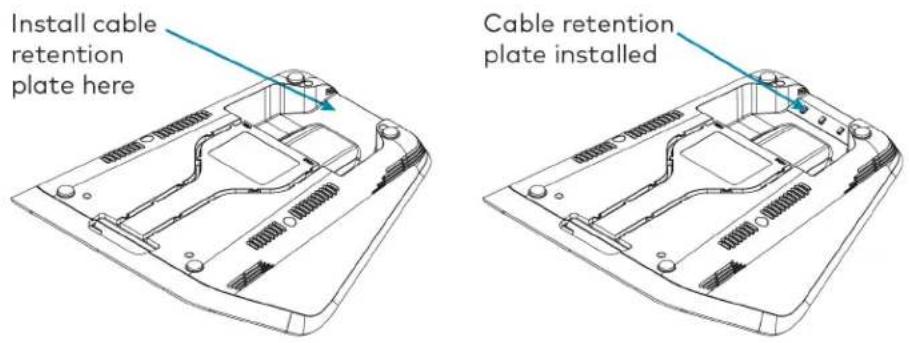
text_image
Install cable retention plate here Cable retention plate installedIdentify the UC Bracket Assembly
The UC Bracket Assembly is available in two models. Identify the model included with your Crestron Flex system. Tap or click the corresponding image below to navigate to the appropriate connection instructions.
UC Bracket Assembly with HD-CONV-USB-200 UC Bracket Assembly with HD-CONV-USB-300

natural_image
Technical line drawing of an electrical enclosure with wiring and components, no visible text or symbols
text_image
Technical schematic diagram of a device with labeled components and wiring connectionsSystem Overview
For UC Bracket Assembly with HD-CONV-USB-200
When connections are complete, the system appears as shown below. Refer to Make Connections on page 208 for detailed connection instructions.
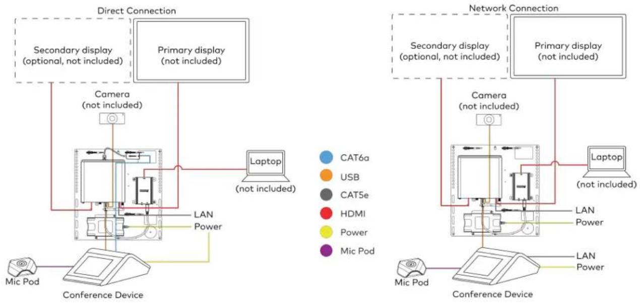
flowchart
graph TD
    subgraph Direct Connection
        A["Secondary display (optional, not included)"]
        B["Primary display (not included)"]
        C["Laptop (not included)"]
        D["Camera (not included)"]
        E["Conference Device"]
        F["Mic Pod"]
    end

    subgraph Network Connection
        G["Secondary display (optional, not included)"]
        H["Primary display (not included)"]
        I["Laptop (not included)"]
        J["Camera (not included)"]
        K["Conference Device"]
        L["Mic Pod"]
    end

    A --> D
    B --> D
    C --> D
    D --> E
    E --> F
    F --> G
    G --> H
    H --> I
    I --> J
    J --> K
    K --> L
    style A fill:#f9f,stroke:#333
    style B fill:#f9f,stroke:#333
    style C fill:#ccf,stroke:#333
    style D fill:#cfc,stroke:#333
    style E fill:#fcc,stroke:#333
    style F fill:#cff,stroke:#333
    style G fill:#ffc,stroke:#333
    style H fill:#ffc,stroke:#333
    style I fill:#cfc,stroke:#333
    style J fill:#fcc,stroke:#333
    style K fill:#cfc,stroke:#333
    style L fill:#fcc,stroke:#333
For UC Bracket Assembly with HD-CONV-USB-300
When connections are complete, the system appears as shown below. Refer to Make Connections on page 208 for detailed connection instructions.
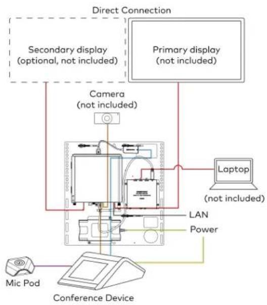
flowchart
graph TD
    A["Primary display (not included)"] --> B["Laptop (not included)"]
    B --> C["Camera (not included)"]
    C --> D["Conference Device"]
    D --> E["Mic Pod"]
    F["Direct Connection"] --> G["Secondary display (optional, not included)"]
    F --> H["Primary display (not included)"]
    I["LAN"] --> J["Power"]
    K["Power"] --> L["Computer"]
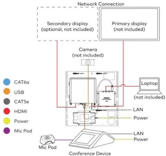
flowchart
graph TD
    A["Cat6a"] --> B["Internet Device"]
    C["USB"] --> B
    D["CAT5e"] --> B
    E["HDMI"] --> B
    F["Power"] --> B
    G["Mic Pod"] --> H["Conference Device"]
    I["Camera (not included)"] --> B
    J["Primary display (not included)"] --> B
    K["Laptop (not included)"] --> B
    B --> L["Network Connection"]
    style A fill:#f9f,stroke:#333
    style C fill:#f9f,stroke:#333
    style D fill:#f9f,stroke:#333
    style E fill:#f9f,stroke:#333
    style F fill:#f9f,stroke:#333
    style G fill:#f9f,stroke:#333
    style I fill:#f9f,stroke:#333
    style J fill:#f9f,stroke:#333
    style K fill:#f9f,stroke:#333
Make Connections
NOTE: For reference, the UC Bracket Assembly is shown with the HD-CONV-USB-200 in the following connection diagrams. Unless otherwise indicated in this guide, the connections remain the same for the UC Bracket Assembly with HD-CONV-USB-200 and HD-CONV-USB-300.
- Make UC Engine connections as shown in the following illustrations. The conference device can communicate with the UC Engine over a direct connection or a network connection. Select one of the connection types as described below.
- Make a direct connection for simple installation and setup. Only use the direct connect adapter to connect the conference device to the UC Engine. Do not use the direct connect adapter to connect the UC Engine to the network.
Direct Connection
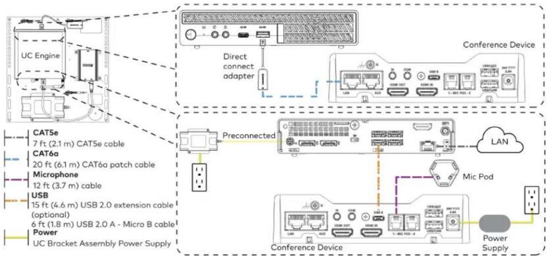
flowchart
graph TD
    A["UC Engine"] -->|Direct connect adapter| B["Conference Device"]
    B --> C["Preconnected"]
    C --> D["Conference Device"]
    D --> E["Power Supply"]

    subgraph CAT5e
        F["7 ft (2.1 m) CAT5e cable"]
    end

    subgraph CAT6a
        G["20 ft (6.1 m) CAT6a patch cable"]
    end

    subgraph Microphone
        H["12 ft (3.7 m) cable"]
    end

    subgraph USB
        I["15 ft (4.6 m) USB 2.0 extension cable (optional)"]
        J["6 ft (1.8 m) USB 2.0 A - Micro B cable"]
    end

    subgraph Power
        K["UC Bracket Assembly Power Supply"]
    end

    L["Microphone"] --> M["USB"]
    M --> N["Micro Pod"]
    N --> O["Conference Device"]
    O --> P["Power Supply"]

    style A fill:#f9f,stroke:#333
    style B fill:#ccf,stroke:#333
    style C fill:#cfc,stroke:#333
    style D fill:#fcc,stroke:#333
    style E fill:#ffc,stroke:#333
    style F fill:#fff,stroke:#333
    style G fill:#fff,stroke:#333
    style H fill:#fff,stroke:#333
    style I fill:#fff,stroke:#333
    style J fill:#fff,stroke:#333
    style K fill:#fff,stroke:#333
    style L fill:#fff,stroke:#333
    style M fill:#fff,stroke:#333
    style N fill:#fff,stroke:#333
    style O fill:#fff,stroke:#333
    style P fill:#fff,stroke:#333
- Make a network connection if the system is to be managed by the XiO Cloud® service.
NOTE: When a network connection is used, disconnect the direct connect adapter from the UC Engine.
Network Connection
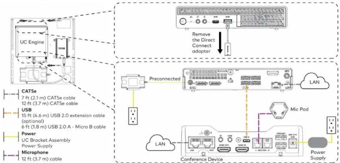
flowchart
graph TD
    A["UC Engine"] -->|Preconnected| B["Conference Device"]
    B --> C["LAN"]
    B --> D["Mic Pod"]
    B --> E["Power Supply"]
    A --> F["Preconnected"]
    F --> G["LAN"]
    F --> H["Conference Device"]
    style A fill:#f9f,stroke:#333
    style B fill:#ccf,stroke:#333
    style C fill:#cfc,stroke:#333
    style D fill:#fcc,stroke:#333
    style E fill:#ffc,stroke:#333
    style F fill:#fcc,stroke:#333
    style G fill:#cff,stroke:#333
    style H fill:#ffc,stroke:#333
- Connect displays to the UC Engine.
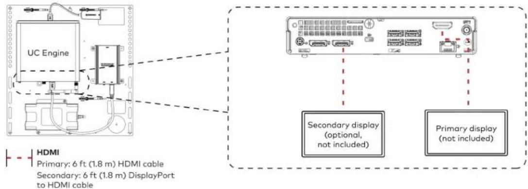
text_image
UC Engine HDMI Primary: 6 ft (1.8 m) HDMI cable Secondary: 6 ft (1.8 m) DisplayPort to HDMI cable Secondary display (optional, not included) Primary display (not included)- Connect the camera to the UC Engine as shown in the image below. Do not connect the camera to any of the other USB ports.
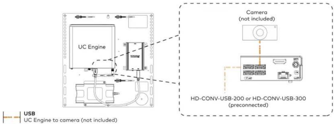
text_image
UC Engine Camera (not included) HD-CONV-USB-200 or HD-CONV-USB-300 (preconnected) USB UC Engine to camera (not included)- Connect a laptop to the HD-CONV-USB-200 or HD-CONV-USB-300.

text_image
UC Bracket Assembly with HD-CONV-USB-200 Laptop (not included) HD-CONV-USB-200 or UC Bracket Assembly with HD-CONV-USB-300 Laptop (not included) HD-CONV-USB-300 HDMI 20 ft (6.1 m) HDMI cable- Bundle the cables to the bracket assembly with the integrated cable tie wraps. The cable tie wraps are reusable.
Bundle Cables
Bundle the cables together and use a provided tie wrap to secure the bundle to one of the positions on the cable retention plate at the rear of the device. Avoid bundling power and data cables together.

text_image
Bundle cables hereApply Power
Press the power button on the bottom of the UC Engine and apply power to all of the other devices in the system. The conference device will display its IP address.
Configure the Conference Device
NOTE: If a Direct Connection was made between the conference device and the UC Engine, skip to Configure the System on page 212.
- On a computer, enter the IP address displayed on the conference device into a web browser.
NOTES:
• The device and computer must be on the same network switch and VLAN.
- A login with administrative rights for the device is required.
-
Log in to the device and navigate to DEVICE > Applications.
-
Enter the following information in the appropriate fields:
- Teams Video PC Address: Enter the IP address or hostname of the UC Engine.
NOTE: The hostname is printed on a label affixed to the UC Engine.
- Teams Video PC Port: By default, port number 49500 is used. If a different port number h been configured on the UC Engine, enter that port number instead.
- Teams Video Username: Enter the login username for the UC Engine. (The default username is "admin".)
-
Teams Video Password: Enter the login password for the UC Engine. (The default password is "sfb".)
-
Select Save Changes.
Configure the System
Use the conference device and your Microsoft Teams credentials to configure the UC Engine, as described in Configuration on page 222. For detailed information on deploying Microsoft Teams Rooms, refer to the Microsoft Teams Rooms documentation.
UC-MX70-NC-T Connections
Minimum Requirements
Ensure that the below requirements are met prior to setting up the system.
• A certified USB Camera (not included).
- A video display (not included) connected to the UC Engine. A second display is optional.
• A Microsoft Teams Rooms provisioned account (not included).
System Overview
When connections are complete, the system appears as shown below. Refer to Make Connections on page 214 for detailed connection instructions.

flowchart
graph TD
    A["Primary display (not included)"] --> B["Camera (not included)"]
    B --> C["Laptop (not included)"]
    C --> D["Conference Device"]
    D --> E["Mic Pod"]
    F["Direct Connection"] --> G["Secondary display (optional, not included)"]
    G --> H["LAN"]
    H --> I["Power"]
    I --> J["Camera (not included)"]
    style A fill:#f9f,stroke:#333
    style B fill:#ccf,stroke:#333
    style C fill:#cfc,stroke:#333
    style D fill:#fcc,stroke:#333
    style E fill:#ffc,stroke:#333
    style F fill:#fcc,stroke:#333
    style G fill:#fff,stroke:#333
    style H fill:#fff,stroke:#333
    style I fill:#fff,stroke:#333
    style J fill:#fff,stroke:#333
    style_K["Water Supply"] --> L["Water Supply"]
    style_M["USB"] --> N["USB"]
    style_O["HDMI"] --> P["HDMI"]
    Q["Power"] --> R["Power"]
    S["Mic Pod"] --> T["Mic Pod"]
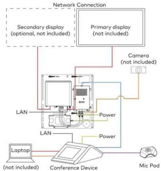
flowchart
graph TD
    A["Primary display (not included)"] --> B["Camera (not included)"]
    A --> C["Secondary display (optional, not included)"]
    A --> D["Laptop (not included)"]
    A --> E["Conference Device"]
    E --> F["Mic Pod"]
    B --> G["Power"]
    C --> H["Power"]
    D --> I["LAN"]
    E --> J["LAN"]
    style A fill:#f9f,stroke:#333
    style B fill:#ccf,stroke:#333
    style C fill:#cfc,stroke:#333
    style D fill:#fcc,stroke:#333
    style E fill:#cff,stroke:#333
    style F fill:#ffc,stroke:#333
    style G fill:#fff,stroke:#333
    style H fill:#fff,stroke:#333
    style I fill:#fff,stroke:#333
    style J fill:#fff,stroke:#333
Make Connections
- Make UC Engine connections as shown in the following illustrations. The conference device can communicate with the UC Engine over a direct connection or a network connection. Select one of the connection types as described below.
- Make a direct connection for simple installation and setup. Only use the direct connect adapter to connect the conference device to the UC Engine. Do not use the direct connect adapter to connect the UC Engine to the network.
Direct Connection

flowchart
graph TD
    A["UC Engine"] --> B["Direct connect adapter"]
    B --> C["Conference Device"]
    D["Preconnected"] --> E["Secondary display (optional, not included)"]
    D --> F["Primary display (not included)"]
    G["Power Supply"] --> H["HDMI Primary: 6 ft (1.8 m) HDMI cable Secondary: 6 ft (1.8 m) DisplayPort to HDMI cable"]
    I["CAT5e 7 ft (2.1 m) CAT5e cable"] --> J["CA76a 20 ft (6.1 m) CAT6a patch cable"]
    K["Power Supply"] --> L["Power"]
    M["LAN"] --> N["TL OUT"]
    N --> O["USB"]
    O --> P["HDMI IN"]
    P --> Q["3 : MAC PORT : 2"]
    Q --> R["USBACC"]
- Make a network connection if the system is to be managed by the XiO Cloud® service.
NOTE: When a network connection is used, disconnect the direct connect adapter from the UC Engine.
Network Connection

flowchart
graph TD
    A["UC Engine"] -->|Remove the Direct Connect adapter| B["Preconnected"]
    B --> C["Secondary display (optional, not included)"]
    B --> D["Primary display (not included)"]
    E["CAT5e 7 ft (2.1 m) CAT5e cable"] --> F["Preconnected"]
    G["HDMI Primary: 6 ft (1.8 m) HDMI cable Secondary: 6 ft (1.8 m) DisplayPort to HDMI cable Power Power supply"] --> H["Preconnected"]
    I["LAN"] --> J["Secondary display (optional, not included)"]
    I --> K["Primary display (not included)"]
- Make a network or direct connection on the bottom of the conference device as described in step 1. Make the remaining content ingest, laptop, mic pod, and power connections. Connect the conference device's power supply to an AC power outlet.

flowchart
graph TD
    A["Device"] -->|LAN (network connection)| B["UC Engine (direct connection)"]
    B --> C["HD-CONV-USB-260"]
    C --> D["Laptop"]
    C --> E["Mic Pod"]
    C --> F["Power supply"]
    B --> G["TCN"]
    B --> H["USB"]
    B --> I["USB/ACC"]
    B --> J["24V 2.5A"]
    B --> K["20 ft (6.1 m) CAT6a patch cable"]
    B --> L["6 ft (1.8 m) thin HDMI cable"]
    B --> M["20 ft (3.7 m) CAT5e cable"]
    B --> N["HDMI"]
    B --> O["Microphone"]
    B --> P["Power supply"]
    B --> Q["USB"]
    style A fill:#f9f,stroke:#333
    style B fill:#ccf,stroke:#333
    style C fill:#cfc,stroke:#333
    style D fill:#fcc,stroke:#333
    style E fill:#cff,stroke:#333
    style F fill:#ffc,stroke:#333
    style G fill:#fcc,stroke:#333
    style H fill:#fcc,stroke:#333
    style I fill:#fcc,stroke:#333
    style J fill:#fcc,stroke:#333
    style K fill:#fcc,stroke:#333
    style L fill:#fcc,stroke:#333
    style M fill:#fcc,stroke:#333
    style N fill:#fcc,stroke:#333
    style O fill:#fcc,stroke:#333
    style P fill:#fcc,stroke:#333
    style Q fill:#fcc,stroke:#333
- Connect the power supply and camera (not included) to the bottom of the content ingest device (HD-CONV-USB-260). Connect the power supplies to an AC power outlet.
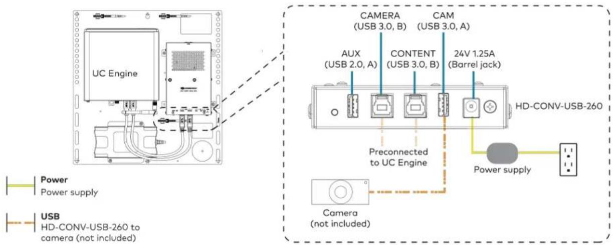
text_image
UC Engine CAMERA (USB 3.0, B) CAM (USB 3.0, A) AUX (USB 2.0, A) CONTENT (USB 3.0, B) 24V 1.25A (Barrel jack) Preconnected to UC Engine HD-CONV-USB-260 Power supply Power Power supply USB HD-CONV-USB-260 to camera (not included) Camera (not included)- Bundle the cables to the bracket assembly with the integrated cable tie wraps. The cable tie wraps are reusable.
Apply Power
Press the power button on the bottom of the UC Engine and apply power to all of the other devices in the system.
Configure the Conference Device
- On a computer, enter the IP address displayed on the conference device into a web browser to configure the device to operate in Teams Video mode.
NOTES:
- The device and computer must be on the same network switch and VLAN.
-
A login with administrative rights for the device is required.
-
Log in to the device and navigate to DEVICE > Applications.
-
Enter the following information in the appropriate fields:
- Teams Video PC Address: Enter the IP address or hostname of the UC Engine.
NOTE: The hostname is printed on a label affixed to the UC Engine.
- Teams Video PC Port: By default, port number 49500 is used. If a different port number h been configured on the UC Engine, enter that port number instead.
- Teams Video Username: Enter the login username for the UC Engine. (The default username is "admin".)
-
Teams Video Password: Enter the login password for the UC Engine. (The default password is "sfb".)
-
Select Save Changes.
Configure the System
Use the conference device and your Microsoft Teams credentials to configure the UC Engine, as described in Configuration on page 222. For detailed information on deploying Microsoft Teams Rooms, refer to the Microsoft Teams Rooms documentation.
Installing Microsoft Teams Rooms Solutions Powered by ASUS UC Engine
To install any Crestron Flex solutions listed below, follow the respective link to the Quick Start guide for instructions.
| Crestron Flex Solutions Quick Start Guide | |
| UC-B30-T Quick Start: UC-B30-T | |
| UC-BX30-T Quick Start: UC-BX30-T | |
| UC-B30-T-WM Quick Start: UC-B30-T-WM | |
| UC-BX30-T-WM Quick Start: UC-BX30-T-WM | |
| UC-C100-T Quick Start: UC-C100-T | |
| UC-C100-T-WM Quick Start: UC-C100-T-WM | |
| UC-CX100-T Quick Start: UC-CX100-T | |
| UC-CX100-T-WM Quick Start: UC-CX100-T-WM | |
| UC-MM30-T | Quick Start: UC-MM30-T(-I) |
| UC-MM30-T-I | |
| UC-MMX30-T | Quick Start: UC-MMX30-T(-I) |
| UC-MMX30-T-I | |
| UC-M50-T Quick Start: UC-M50-T | |
| UC-M50-T-UPGRD Quick Start: UC-M50-T-UPGRD | |
| UC-MX50-T | Quick Start: UC-MX50-T |
| UC-MX50-T-UPGRD | Quick Start: UC-MX50-T-UPGRD |
| UC-M70-T | Quick Start: UC-M70-T |
| UC-MX70-T | Quick Start: UC-MX70-T |
UC-MM30-TA and UC-MM30-TA-I Installation
Minimum Requirement
Ensure that the below requirements are met prior to setting up the system.
A Microsoft Teams Rooms provisioned account (not included).
In the Box
Qty. Description
| 1 Flex MM Tabletop Conference Device, Microsoft Teams audio (6510609 or 6511099) |
| Additional Items |
| 1 1 PoE+ injector (2055605) |
| 2 Cable, CAT5e, RJ-45 - RJ-45, 11.8 ft (3.6 m) (2056204) |
| 1 Cable, USB 2.0, A - Micro B, 5.8 ft (1.8 m) (2055579) |
Connections
Make device connections as shown below.
NOTE: A laptop connection to the conference device is optional. When connected, the conference device acts as a speakerphone.

flowchart
graph LR
    A["Router"] --> B["PoE+ Injector"]
    B --> C["Conference Device"]
    D["Laptop (optional)"] --> E["Cloud"]
    E --> B

CAT5e or better
11.8 ft CAT5e cable (x2)

USB
5.8 ft USB 2.0 A - Micro-B cable

Power
PoE+ Injector
Sign Into the Microsoft Teams Service
When prompted by the tabletop conference device, tap Sign In at the bottom of the screen and follow the displayed instructions to sign into the Microsoft Teams service.
Configure the Device
Use the on-screen instructions to configure the device. The default password to access the administrator settings is "admin." Choose a new password when prompted.
Factory Reset
A factory reset may be performed when troubleshooting the conference device.
To perform a factory reset on the conference device:
-
Power cycle the device by disconnecting and reconnecting the CAT5e cable from the conference device.
-
When the device powers on and the LEDs flash green, tap the button below the Crestron® logo 10 times. A factory reset confirmation screen appears.

text_image
Tap x10- Tap one of the mute buttons to move the selector on the factory reset confirmation screen to Yes. Tap the button below the Crestron logo to confirm the factory reset.
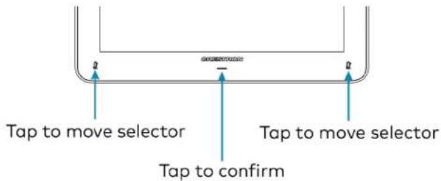
text_image
Tap to move selector Tap to confirm Tap to move selector- The device will reboot.
NCC警语
NCC Regulatory Information Support Frequency Bands and Power: BT< 8 dBm; WLAN 2412-2462 MHz < 25 dBm; WLAN 5150-5825 MHz < 18 dBm;
Configuration
Microsoft Teams Rooms Deployment and Setup
Minimum Requirements
The following is required to set up a Microsoft Teams Rooms Platform Administrator account.
• A Microsoft Teams Rooms provisioned account (not included)
- Microsoft 365 administrator access to create resource accounts and assign licenses. For more information on required licenses, see the Online Licensing.
- For more information on deploying Microsoft Teams Rooms systems, visit Microsoft Teams deployment overview.
Pre-Deployment Checklist
Complete the following tasks to ensure successful deployment of your Crestron® Flex conference room solution.
| Task Requirement Notes | ||
| Verify Accounts/Configure Solution | Microsoft Teams Rooms account credentials | Account credentials are required to log in to Microsoft Teams Rooms. When purchasing a Crestron Flex for use with Microsoft Teams Rooms, the Microsoft Teams desktop client is preinstalled on the UC-ENGINE.For guidelines on how to configure accounts for Microsoft Teams Rooms, visitConfigure accountsfor Microsoft Teams Rooms. |
| Confirm Connection Points Two (2) | Gigabit LAN Ports Ensure the installation space has two available gigabit LAN ports connected to the same VLAN on the same network. | |
| Configure Network Server Configure your network to provide an IP address using DHCP. | The UC-ENGINE and tabletop device communicate over a VLAN network connection and require access to the Internet. Port 49500 is used by default.NOTE:Microsoft TeamsRooms may not be configured with a static IP address upon initial startup.Run the Microsoft Network Assessment Tool to confirm that your network is properly configured. For more information, visitEvaluate my environment. | |
| Establish Network Communications | Open the required TCP and UDP ports. | Open TCP ports 80 and 443 and UDP ports 3478 through 3481. The TCP ports are used to connect to Microsoft's Online Services, such as SharePointTM Online, Exchange Online, and the Teams Chat services.For more information, visitPrepare your network. |
Initial Setup
-
Connect and start your selected solution as described in Installation and Connections on page 77.
-
Follow the on-screen prompts as displayed on the control device to complete the setup. For detailed instructions on planning, deploying, and managing Microsoft Teams Rooms systems, refer to Microsoft's documentation.
Microsoft Teams Rooms Software Updates
Software updates for Microsoft Teams Rooms systems and associated control devices (Crestron Mercury devices or touch screens) are performed through the UC Engine's Windows Update service.
NOTE: For information on managing Windows updates, refer to Manage Windows Updates.
The Microsoft Teams Rooms application is updated from the Windows Store.
Control device firmware provided by the Windows Update service may be an earlier version than firmware available on the Crestron website. Control devices running higher firmware versions than that contained in the Windows Update package will be downgraded to the firmware contained in the Windows Update package.
Microsoft Teams Rooms systems can be managed with Microsoft Intune® software. For more information, visit Managing Teams Meeting Rooms with Intune.
Crestron Settings App
After setting up Microsoft Teams Rooms, use the Crestron Settings app for further configuration.
NOTE: Crestron recommends using a keyboard and mouse connected to the UC Engine when using the Crestron Settings app. If a USB port is not available, temporarily disconnect the system's camera.
To open the Crestron Settings App, click 📋 > Crestron folder > Crestron Settings. The Crestron Settings app opens.
NOTE: When opening the Crestron Settings app for the first time, you must agree to the CRESTRON UNIFIED COMMUNICATIONS SOFTWARE LICENSE AGREEMENT. Click I Agree to continue to the Crestron Settings app.
Crestron Settings App

Settings
System
USB Camera
Content Input
Load Project
IP Table
Diagnostics
Advanced
System Information
UC-ENGINE Unified Collaboration System [v1.14.00.176,362152NAA01376]
MS Teams Rooms App version: 4.19.60.0
Serial Number: 2152NAA01376
IP Address: 169.254.158.143
© 2008 - 2022 Cractron Electronics Inc.
Room Devices
Type
Device
Firmware
IP Address
Status
Content
HD-CONV-USB-200 51.9
Controller
Crestron Remote
1.11.00.064
192.168.5.117
Room Camera
Huddy IQ
1.6.12-126903
System
Use the System menu to view firmware versions of connected system devices and the firmware packages stored on the UC Engine.
System

Settings
System
USB Camera
Content Input
Load Project
IP Table
Diagnostics
Advanced
System Information
UC-ENGINE Unified Collaboration System [v1.14.00.176, %2152NAA01376]
MS Teams Rooms App version: 4.19.60.0
Serial Number: 2152NAA01376
IP Address: 169.254.150.143
© 2006. 2022 Crestron Electronics Inc
Room Devices
Type
Device
Firmware
IP Address
Status
Content
HD-CONV-USB-200 51.9
Controller
Crestron Remote 1.11.00.004
192.1685.117
Room Camera
Huddly IQ
1.6.12-126903
USB Camera
Click USB Camera to display the USB Camera menu.
Use the USB Camera menu to adjust the zoom, tilt, and pan, recall preset settings, store preset settings, and control the Genius Framing feature (available for specific cameras).
USB Camera

Settings
System
USB Camera
Content Input
Load Project
IP Table
Diagnostics
Advanced
USB Camera Controls
Up to 4 different presets can be saved to fine-tune camera positioning. The preset that is selected here will be saved when using the system. Presets can also be changed with a SmartGraphics project. These are digital controls, so zooming in will decrease camera resolution.
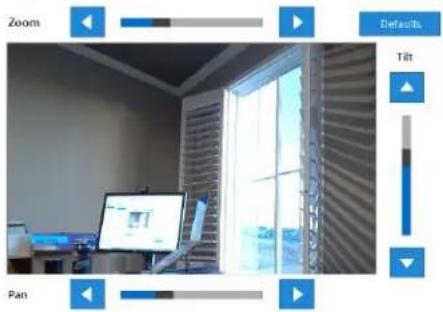
text_image
Zoom Defaults Tilt PanSelect the desired preset to the right and use the controls above to position the camera as needed. Press Save to set the currently selected preset.

Camera Presets
None
Preset 1
○ Preset 2
○ Preset 3
○ Preset 4
[NO TEXT]
Bone
Adjust Tilt, Pan, or Zoom
The tilt, pan, and zoom on a connected camera can be remotely adjusted from the USB Camera screen.
NOTE: Tilt, pan, and zoom settings may not work with all cameras.
To make an adjustment, select a preset and adjust as necessary.
- Click Zoom I or H to adjust the amount of zoom.
- Click Pan I or H to adjust the pan.
- Click Tilt K or J to adjust the camera tilt.
- Click Defaults to return the camera to its default settings.
Save a Preset
Tilt, pan, and zoom settings can be saved for recall later. To save a preset setting:
- Click one of the four available Camera Presets locations on the right side of the display.
- Adjust the tilt, pan, and zoom as described in Adjust Tilt, Pan, or Zoom on page 228.
- Click Save To Preset to save the settings.
Recall a Preset
Click a Preset on the right side to recall a preset.
Genius Framing (systems with a CCS-CAM-USB-F-400 or UC-SB1-CAM-FLEX)
Crestron Flex solutions that use a CCS-CAM-USB-F-400 Huddly IQ™ Collaboration Camera or a UC-SB1-CAM-FLEX UC Video Conference Smart Soundbar & Camera can use the camera's built-in Genius Framing feature. Genius Framing automatically detects and frames people in the camera's field of view.
By the default, Genius Framing is set to ON. Set the switch to OFF to disable Genius Framing.
NOTE: Genius Framing can be controlled by the XiO Cloud service if the UC Engine is registered with the service.
Content Input
Click Content Input to display information about the HDMI content input.
Content Input

Settings
System
USB Camera
Content input
Load Project
IP Table
Diagnostics
Advanced
HDMI Content Input
Current Input:
1920x1080
60 Hz
Input Color Space
Limited
Full
Auto (Default)

text_image
CRESTRON Products How to Buy Support Partners Training & Event Connect Us News Regular Sign In Data is lost on PC-enabled/Max-EpDInfo at Local Press - Local PressDone
Select one of the following settings of the Input Color Space feature:
- Limited: Select if the black portion of the image appears washed out.
• Full: Select if the shadow detail of the picture appears missing. - Auto (Default): Default setting (selected by default).
Load Project
Crestron Flex can use custom controls as part of a Crestron control system.
Click Load Project to display the Load Project menu.
Microsoft Teams Rooms systems with a Crestron Mercury conference system or a touch screen use the Smart Graphics™ menu to upload a touch screen project with custom controls as part of a Crestron control system. Touch screen projects are loaded to the system from a connected USB drive.
NOTE: A touch screen project can also be remotely uploaded to the system by tools such as Crestron Toolbox™ software or the XiO Cloud service. For more information, refer to the Crestron Toolbox help file and the XiO Cloud Service User Guide (Doc. 8214).
Load Project

text_image
Settings System USB Camera Content Input Load Project IP Table Diagnostics Advanced Load User Project Current Project Name: Crestron-MTRCameraHAF-v2 Date Created: 10/25/2023, 01:13:20 PM Load New ... DoneTo upload a touch screen project on a Microsoft Teams Rooms system:
- Connect a USB drive containing the project to a USB port on the UC engine.
- Click Load New.
- Navigate to the location of the project file and click Open. The project loads to the system.
NOTE: When loading a project for the first time, you can either reboot the UC engine to load the project to the control device immediately or wait up to 20 minutes for the control button to display on the control device.
IP Table
Click IP Table to display the IP Table menu.
Configure the IP table to allow Crestron Flex to be used as part of a Crestron control system. An IP table is a lookup table used by Crestron Ethernet devices to map between IP IDs and IP addresses. Use the IP Table menu to enable and configure the system for communication with a Crestron control system.
NOTE: A Crestron Flex's IP table can also be configured by Crestron Toolbox software. For more information, refer to the Crestron Toolbox help file.
IP Table

Settings
System
USB Camera
Content input
Load Project
IP Table
Diagnostics
Advanced
Crestron IP Table
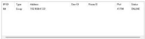
text_image
IPID 64 Tjsw Address 150 808.4122 DevID Place ID Post 41754 Status ONLINEIP ID: Type (Gway IP Address/Hostname: Room ID* Device ID (JNR) * Port (41794)*

Update Selected
Fairview
Add
* Entries are optional and if not specified, the default will be used.
Automatically discover and respond to other Crestrose devices
On

Allow multiple IP Table entries
On

Done
IP Table Entries
Entries in an IP table identify the control system(s) that can control Crestron Flex. Entries can be added, updated, or removed.
- Add an Entry
a. From the IP ID drop-down list, select the system's IP ID as specified in the control system's program.
NOTE: The IP ID must match the IP ID specified for the system in the control system's program.
b. Enter the IP address or hostname in the IP Address/Hostname field.
c. If using a port other than 41794 for communications with the control system, enter it in the Port (41794)* field.
NOTE: This field is optional. If left blank, the default port (41794) is used.
d. Click Add.
- Modify an Entry
a. Click an entry in the IP table.
b. Select the new IP ID, address or hostname, and port.
c. Click Update Selected.
- Remove an Entry
a. Click an entry in the IP table.
b. Click Remove.
Other IP Table Functions
Set the Automatically discover and respond to other Crestron devices setting to Off to hide the system from being discovered by other devices during auto-discovery.
Multiple control systems listed on the IP table can be allowed to control the system. Set the Allow multiple IP Table entries setting to Off to allow only one control system on the IP table.
Crestron SSL
The system can use SSL technology when connecting to a Crestron control system. To configure the system to use SSL for control system communications:
- Set the Use SSL for control system connections setting to Enabled.
- If certificate authentication is used, set the Certificate Authentication setting to On.
- Enter the login credentials in the Username and Password fields.
Diagnostics
Click Diagnostics to display the Diagnostics menu.
Use the Diagnostics menu to view and manage system logs.
Diagnostics
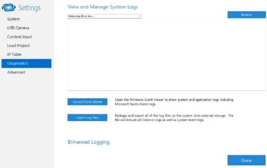
text_image
Settings System USB Camera Content Input Load Project IP Table Diagnostics Advanced View and Manage System Logs Select a log file to view... Refresh Launch Event Viewer Open the Windows Event Viewer to show system and application logs including Microsoft Teams Room logs. Export Log Files Package and export all of the log files on the system onto external storage. The file will include all Crestron logs as well as system event logs. Enhanced Logging DoneView Logs
When troubleshooting, different logs can be viewed. First, select the desired log file from the View and Manage System Logs drop-down list to view a specific log type. Then, click Refresh to view the latest log data.
Windows Event Viewer
Click Launch Event Viewer to open the Windows event viewer that shows system and application logs.
Export Log Files
Click Export Log Files to package and export all the log files (including all Crestron logs and system event logs) onto external storage.
Upload Log Files
Click Upload Log Files to package and upload all the log files to a Crestron server for delivery to Crestron support personnel.
NOTE: Internet access is required for uploading.
Enhanced Logging
Enable the enhanced logging feature only if instructed by Crestron support for advanced troubleshooting. The enhanced logs are collected during the normal export process. Turn off enhanced logging when troubleshooting is finished.
Advanced
Click Advanced to display the Advanced menu.
Use the Advanced menu to configure the system with MyCrestron and Crestron Fusion software in the Cloud, to switch the UC Engine application mode, or to make the Soundbar firmware mode selection (UC-SB1-CAM-FLEX only).
Advanced
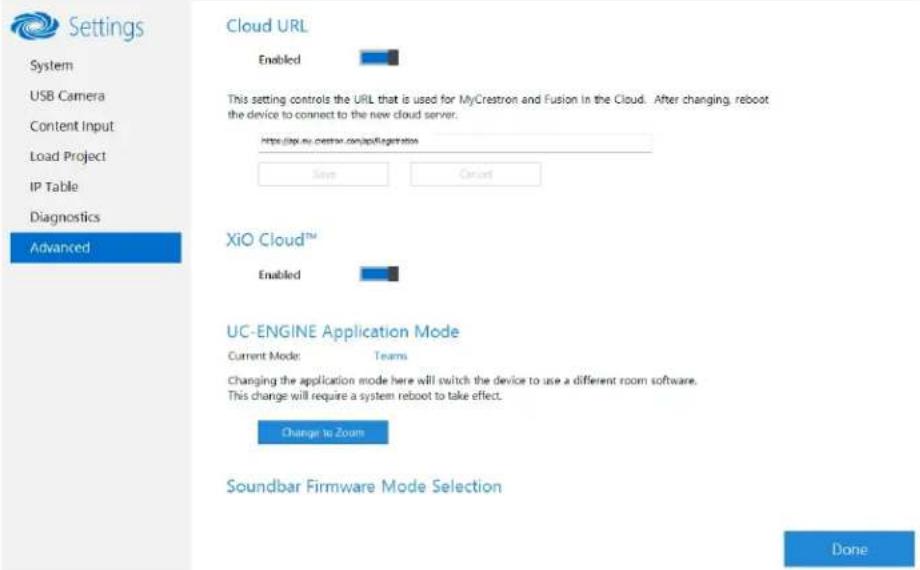
text_image
Settings System USB Camera Content Input Load Project IP Table Diagnostics Advanced Cloud URL Enabled This setting controls the URL that is used for MyCrestron and Fusion in the Cloud. After changing, reboot the device to connect to the new cloud server. https://my.crestron.com/applification/ Save Cancel XiO Cloud™ Enabled UC-ENGINE Application Mode Current Mode: Teams Changing the application mode here will switch the device to use a different room software. This change will require a system reboot to take effect. Change to Zooms Soundbar Firmware Mode Selection DoneCloud URL
Enter the URL of the Crestron Fusion server. Upon completion, the system should be brought into Crestron Fusion software as a processor. For more information, refer to the Crestron Fusion software help file.
UC-ENGINE Application Mode
Many Crestron Flex solutions that support dual displays can switch from the Microsoft Teams Rooms application to the Zoom Rooms application.
NOTE: This functionality is supported by the ASUS UC engine only.
For more details on switching applications, refer to Switching from Microsoft Teams Rooms to Zoom Rooms on page 237.
Soundbar Firmware Mode Selection (for systems with UC-SB1-CAM-FLEX only)
Crestron Flex with a UC-SB1-CAM-FLEX UC Video Conference Smart Soundbar can be used with firmware that provides superior sound quality or higher volume output.
If a soundbar is connected to the system, click a firmware version to install it.
Return to the Conference System
After all changes have been made, the system should be returned to regular operation. To return to regular operation:
- Click Done to return to the Windows desktop.
- Click A menu is displayed.
- Click 8 and then click Sign Out. The Administrator login screen is displayed.
- Click Skype.
- Click Sign in. The Microsoft Teams Rooms application will start.
NOTE: If a camera was disconnected from the UC Engine to use a keyboard, disconnect the keyboard, and connect the camera to the UC Engine.
Switching from Microsoft Teams Rooms to Zoom Roof
Minimum Firmware Requirements
• UC Engine: 1.00.16.715b
• TSW-1060 touch screen: 2.006.0063.001
• TS/TSW-1070 touch screen: 1.001.0014.001
• UC-2 Mini Tabletop conference device: 1.0.1.59
• CCS-UC-1-T-V Crestron Mercury Tabletop UC Video Conference Console: 1.4906.00015.001
• CCS-UC-1-X Crestron Mercury X Tabletop Console: 1.4160.00050.001
Change UC Engine Settings
Use one of the following methods to change the UC Engine settings:
- Crestron Settings App
NOTES:
Some dual display systems cannot switch from the Microsoft Teams Rooms to the Zoom Rooms application. For example, if the Crestron Settings app does not show the Change to Zoom button, the system does not support the mode switch function.
° If the XiO Cloud service manages the UC Engine, changes made in the Crestron Settings app will revert to the settings established by the XiO Cloud service.
- Crestron recommends using a keyboard and mouse connected to the UC Engine when using the Crestron Settings app. If a USB port is not available, temporarily disconnect the system's camera.
- Open the Crestron Settings app as described in Crestron Settings App on page 226.
- Click Advanced.
- Click Change to Zoom and click Ok to confirm. The system will reboot.
- XiO Cloud Service
NOTE: Changes made from the XiO Cloud service will override any settings made from the Crestron Settings app.
- Log in to the XiO Cloud service and select the UC Engine to switch.
- Click the Settings tab.
XiO Cloud, UC Engine, Settings tab

text_image
United States > Flex Teams Systems > M150-T HQ15-275 ✓ Action ✓ Status Settings Activity Log The system is currently online ► System Setup ► Services ► Applications Application Mode Team Video ► CCS-CAM-USB-F-400 © 2010 Construction Networks, Inc. Release: L15214 Service Status | Privacy Statement | Cloudware License- Click Applications.
NOTE: Some dual display systems cannot switch between the Microsoft Teams Rooms and the Zoom Rooms application. If the Settings tab does not contain an Applications menu, the system does not support the mode switch function.
-
Click the checkbox next to Application Mode to have the XiO Cloud service manage the device.
-
Select Zoom Rooms from the Application Mode drop-down list. XiO Cloud, UC Engine, Settings tab, Zoom Rooms selected
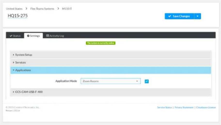
text_image
United States > Flex Teams Systems > M150-T HQ15-275 Save Changes ✓ Status Settings Activity Log The system is currently inside ► System Setup ► Services ► Applications Application Mode Zoom Rooms ► CCS-CAM-USB-F-400 ©2000 Creation Electronics, Inc. Reverse 115114 Service Status | Privacy Statement | Cloudflare License- Click Save Changes. The device will reboot.
Change the Control Device's Application Mode
Set the control device's Application Mode to Zoom Rooms on:
Crestron Mercury Conference Systems
Use one of the following methods to change the Mercury conference system's application mode.
- Web Browser
NOTE: If the XiO Cloud service manages the Crestron Mercury device, any changes made in the web browser will revert to the settings established by the XiO Cloud service.
- Use a web browser to display the DEVICE screen of the Crestron Mercury device's configuration pages. For more information, refer to the CCS-UC-1 Product Manual (Doc. 7844).
Web browser, Crestron Mercury Device, Device menu, Applications

text_image
CRESTRON STATUS HKEY INPUT HEART OUTPUT NETWORK APPRO APPVICE SVC APPRO ARROZARID • Data Management • Auto Update • Web Calling • Course Date/Time • Shipout For Business • Authentication Management Application Mode: Source Video Source Video Source Video PC Address: CA-14820333 Source Video PC Port: 95500 Source Video Customer: Active Source Video Password: © 2025 Crestron Electronics, Inc. Private https://www.crestron.com/sales/cegar@crestron.com- Select Zoom Rooms from the Application Mode drop-down list.
Web browser, Crestron Mercury Device, Device menu, Applications, Zoom Rooms selected

text_image
CRESTRON STATUS EXP INPUT/ EAST OUTPUT NETWORK ACCESS ACCESS ACCESS ACCESS ACCESS • Device Management • Audio Cluster • 3D Printing • Hardware Display/Box • Display For Software • Authentication Management Application Mode: Zone Users Power Source: Ultra user Volume Percent: 70 © 2020 Crestron Devices Inc. Access Services | Access Office Communication Software License Agreements-
Adjust the Zoom Ultrasonic Volume setting for use with the Zoom Rooms direct sharing feature. For more information, refer to Direct sharing in Zoom Rooms.
-
Click Save Changes. The device will reboot.
- XiO Cloud Service
NOTE: Changes made from the XiO Cloud service will override any settings made from the device.
- Log in to the XiO Cloud service and select the Crestron Mercury device to switch.
- Click the Settings tab.
- Click Applications.
XiO Cloud, Crestron Mercury Device, Settings tab, Applications
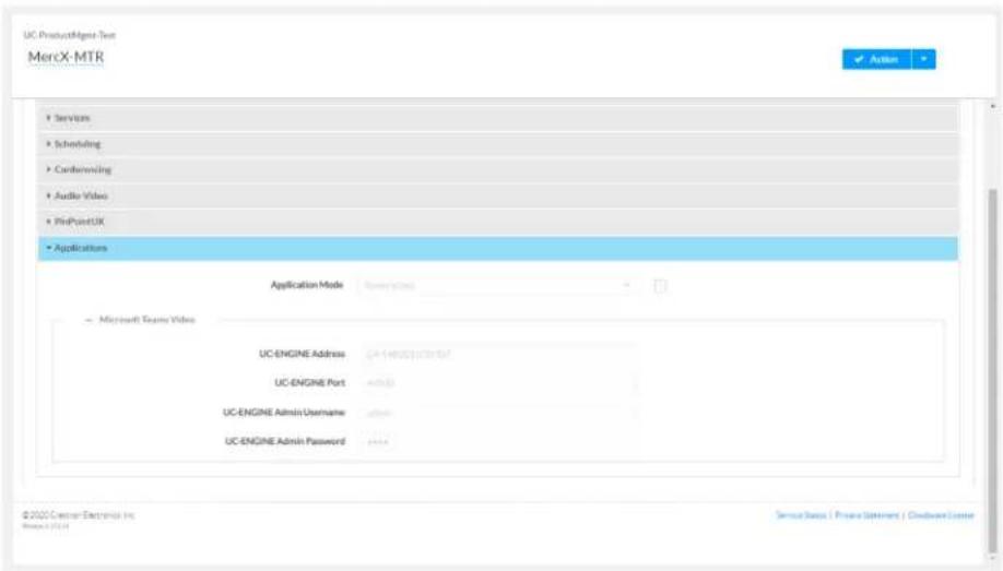
text_image
UC ProductMigr Test MercX-MTR ■ Services ■ Scheduling ■ Confinancing ■ Audio Videos ■ PinPointUX ■ Applications Application Mode ■ Microsoft Teams Video UC-ENGINE Address CA1-40000000000000000000000000000000000000000000000000000000000000000000000000000000000 UC-ENGINE Port admin UC-ENGINE Admin Username admin UC-ENGINE Admin Password admin © 2022 Cserer Exchange Inc. Status: 1971 Service Status | Private Statement | Cloudware Center- Click the checkbox next to Application Mode to have the XiO Cloud service manage the device.
- Select Zoom Rooms from the Application Mode drop-down list.
XiO Cloud, Crestron Mercury Device, Settings tab, Applications, Zoom Rooms selected
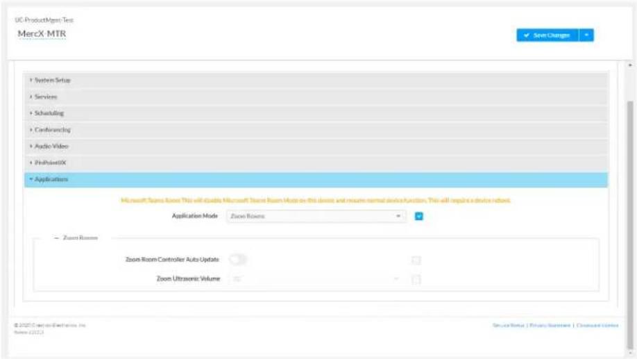
text_image
UC ProductMgmt Test MercX MTR System Setup Services Scheduling Cardflowlog Audio Video ProPointIX Applications Microsoft Teams Know This will divide Microsoft Teams Room Mode on this device and resume normal device function. This will replace a device network. Application Mode Zoom Rooms Zoom Room Zoom Room Controller Auto Update Zoom Ultrasonic Volume © 2020 Commercial Exchanges Inc. Series (2017) ServiceNow | Privacy/Environment | Command/Services-
Click Save Changes. The device will reboot.
-
Set the device's Zoom Room settings.
-
Enable Zoom Room Controller Auto Update to have the Crestron Mercury device automatically download updates as they are published.
° Adjust the Zoom Ultrasonic Volume setting for use with the Zoom Rooms direct sharing feature. For more information, refer to Direct sharing in Zoom Rooms. -
Click Save Changes.
Touch Screens
Use one of the following methods to change the touch screen's application mode.
- Web Browser
NOTE: If the touch screen is managed by the XiO Cloud service, any changes made in the web browser will revert to the settings established by the XiO Cloud service.
- Use a web browser to display the Applications settings of the touch screen's configuration pages. For more information, refer to the TSW-570, TSW-770, and TSW-1070 Product Manual (Doc. 8550) or TS-770 and TS-1070 Product Manual (Doc. 8555).
Web browser, Touch Screen Device, Settings tab, Applications
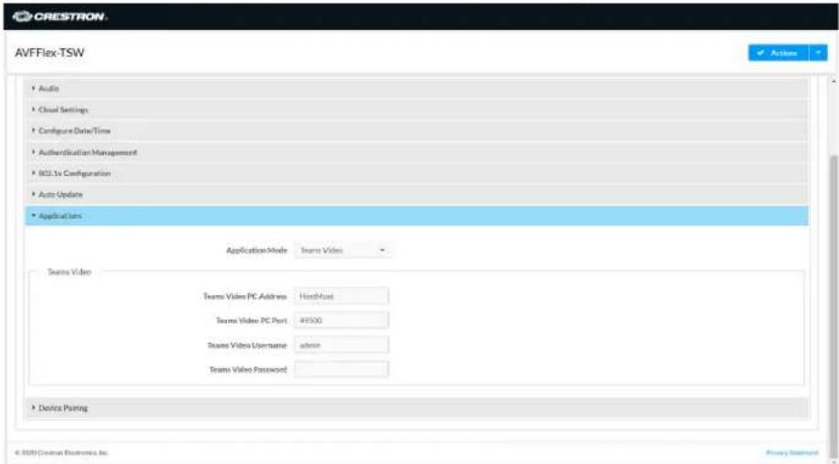
text_image
AVFFlex-TSW Audio Cloud Settings Configure Data/Time Authentication Management M2.1x Configuration Auto Update Applications Application Mode Teams Video Teams Video Teams Video PC Address HostMust Teams Video PC Port 49500 Teams Video Username admin Teams Video Password Device Planing © 2007 Crestrat Electronics, Inc. Privacy Standard- Select Zoom Rooms from the Application Mode drop-down list.
Web browser, Touch Screen Device, Settings tab, Applications, Zoom Rooms selected
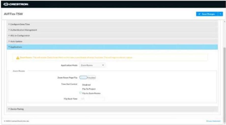
text_image
CRESTRON AVFFlex-TSW Configure Date/Time Authentication Management 802.1x Configuration Auto Update Applications Zoom Rooms: Flip will update Zoom Room Marks on this session and locate all other locations. The will require immediate setup Application Mode Zoom Rooms Zoom Rooms Zoom Room Page Flip Disabled Time Out Control Disabled Flip To Project Flip to Zoom Rooms Flip Back Time 350 Device Pairing © 2000 Crestron Electronics, Inc.- If the touch screen is to flip between Zoom Rooms and a custom touch panel project, configure the page flip operation below.
a. Use a web browser to display the Applications settings of the touch screen's configuration pages.
b. Set Zoom Room Page Flip to Enabled.
c. Set Time Out Control to the automatic flip behavior for the Zoom Rooms application.
- Disabled: Automatic flip behavior is disabled.
- Flip To Project: The screen automatically flips to the user project after the Flip Back Time duration elapses. Press the home button (second hard key from top right) on the touch screen to flip back to the Zoom Rooms application.
- Flip To Mode: The screen automatically flips to the Zoom Rooms application after the time-out duration elapses. Press the home button on the touch screen to flip back to the user project.
d. Set Flip Back Time to a time (1 to 100 minutes) before the automatic flip behavior occurs.
- Click Save Changes. The device will reboot.
NOTE: The touch screen automatically updates the Zoom Rooms application weekly. If an update is needed sooner, click Actions, and then click App Upgrade.
- XiO Cloud Service
NOTE: Changes made from the XiO Cloud service will override any settings made from the device.
- Log in to the XiO Cloud service and select the touch screen device to switch.
- Click the Settings tab.
- Click Applications.
XiO Cloud, Touch Screen Device, Settings tab, Applications

text_image
United States > Fox Teams Systems > B340 T TSW-1060-00107FDO Status Settings Remote Control Set Dashboard Activity Log Scheduled Actions File Management To existing System data System Setup Services Network Price Settings Audio Applications Application Mode Status Microsoft Teams Video UC-ENGINE Address: 12.000.000.000.000.000.000.000.000.000.000.000.000.000.000.000.000.000.000.000.000.000.000.000.000.000.00 UC-ENGINE Port: 12.000.000.000.000.000.000.000.000.000.000.000.000.00 UC-ENGINE Admin Username: 12.000.000.000.000.000.000.000.000.00 UC-ENGINE Admin Password: 12.001.12.12.12.12.12.12.12.12.12.12.12.12.12.12.12.12.12.12. Control System © 25th Cenner Electronics Inc. Name: 1/2/24 Service Status | Privacy Statement | Customers License-
Click the checkbox next to Application Mode to have the XiO Cloud service manage the device.
-
Select Zoom Rooms from the Application Mode drop-down list.
XiO Cloud, Touch Screen Device, Settings tab, Applications, Zoom Rooms selected

text_image
United States > Film Teams Systems > B3407 TSW-1060-00107FDO Status Settings Remote Control Default Dashboard Activity Log Scheduled Actions File Management Application currently valid Systems Setup Services Network Proxy Settings Audio Applications Microsoft Teams Resort This will allocate Microsoft Teams Resort Mark on the device and account normal device function. This will require a device version. Application Mode Zoom Rooms Zoom Rooms Zoom Room Page Flip Time Out Control DisasSED Flip To Project Flip To Mode FlipBack Time (In Minutes) Minutes Control System © 2020 Custom Enterprise Inc. BASF 2020 Service Status | Privacy Statement | Command/Home- If the touch screen is to flip between Zoom Rooms and a custom touch panel project, configure page flip operation.
a. Set Zoom Room Page Flip to Enabled.
b. Set Time Out Control to the automatic flip behavior for the Zoom Rooms application.
- Disabled: Automatic flip behavior is disabled.
- Flip To Project: The screen automatically flips to the user project after the Flip Back Time duration elapses. Press the home button (second hard key from top right) on the touch screen to flip back to the Zoom Rooms application.
- Flip To Mode: The screen automatically flips to the Zoom Rooms application after the time-out duration elapses. Press the home button on the touch screen to flip back to the user project.
c. Set Flip Back Time to a time (1 to 100 minutes) before the automatic flip behavior occurs.
- Click Save Changes. The device will reboot.
Operation
For instructions on using a Microsoft Teams Rooms solution, visit Getting Started with a Microsoft Teams Rooms Solution.
Zoom Rooms® Solution
Crestron Flex makes any space a productive Zoom Room. From hotdesking to training rooms, Crestron Flex products deliver the optimum audio and video to each space. With the ease of one-touch join and the ability to effortlessly move a meeting from the desktop to the conference room, Crestron Flex enables teams to work together more efficiently. For more details regarding Crestron Flex and Zoom Rooms collaboration, refer to Crestron Flex + Zoom Rooms.
Select the following sections to learn about the product features, specifications, installation, configuration, and operation for all UC B30/BX30, UC B70, C100/CX100, MM30/MMX30, M50/MX50, and M70/MX70 series Zoom Rooms solutions.
- Features
- Specifications and Dimension Drawings
• Installation and Connections - Configuration
- Operation
Features
Refer to the following sections for more information on the features provided by various Zoom Rooms solutions.
UC-B30-Z and UC-B31-Z Series Features
The UC-B30-Z and UC-B31-Z series standard Crestron Flex tabletop front-of-room video conferencing system provides a small room video conference solution for use with Zoom Rooms software. It supports up to three video display(not included).
natural_image
Exterior view of a modern office building (no signage)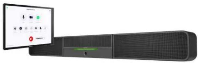
natural_image
Exterior view of a modern office building (no signage)UC-B31-Z / UC-B31-Z-INDIA UC-B31-Z-WM / UC-B31-Z-WM-INDIA

natural_image
Black cylindrical electronic device with a digital display showing app icons and status bar (no readable text or symbols)
natural_image
Black cylindrical audio player with a speaker, displayed next to an adjacent digital interface showing control buttons and playback controls (no readable text or symbols on device)Included Components
| UC-B30-Z | UC-B31-Z(-INDIA) | UC-B30-Z-WM | UC-B31-Z-WM(-INDIA) | |
| UC-SB1-CAM-FLEX | √ | ✗ | √ | ✗ |
| UC-SB-P50 or UC-SB-P50-INDIA | ✗ | √ | ✗ | √ |
| TS-1070-B-S | √ | √ | ✗ | ✗ |
| TSW-1070-B-S | ✗ | ✗ | √ | √ |
| UC-BRKT-200-S-Z-ASSY | √ | √ | √ | √ |
| PoE Injector | √ | √ | √ | √ |
| Cables | √ | √ | √ | √ |
To view the specifications and dimensions of the included components of the selected kit, refer to Specifications and Dimension Drawings.
Key Features
- Front-of-room video conferencing solution for Zoom Rooms software
- Native Zoom Rooms touch screen UI provides a consistent user experience with simple operation and one-touch meeting joins
• Network management and provisioning and system alerts through the XiO Cloud® service
• Supports up to three video displays (not included) - Easy to specify and install — no custom design, programming, or software installation required
- Enterprise-grade security — connects and communicates securely over any enterprise or SMB network
- Premium-level support with Crestron Flex Care (optional)
Native Zoom Rooms Software Experience
The conferencing solution features Zoom Rooms conferencing software that enables audio and video connectivity for easy collaboration and content sharing.
Intuitive User Interface
With a large 10.1 in. (257 mm) capacitive touch screen display, the Crestron tabletop or wall mount touch scree provides superior conferencing control in meeting rooms, huddle spaces, and executive offices.
Using the bracket provided with the wall mount touch screen, the touch screen is easily installed over a 2-gang or 3-gang US electrical box, or a 2-gang European or UK electrical box. A security latch option is included to deter unauthorized removal of the touch screen.
Simplified Deployment
The UC Bracket Assembly provides preassembled components on one ready-to-mount bracket to simplify installation. The assembly can be mounted on a wall, or it can be attached to the rear of the display device.
High-Definition Video Conferencing with Impressive Audio
UC-SB1-CAM-FLEX: High-quality speakers, microphone, and digital signal processing deliver exceptional full-duplex speakerphone performance from the Crestron UC video conference soundbar and camera (UC-SB1-CAM-FLEX). The built-in conferencing camera captures the room in HD 1080p video resolution and with an ultra-wide 150° diagonal field of view.
UC-SB-P50 or UC-SB-P50-INDIA: High-quality speakers and microphones deliver exceptional full-duplex performance from the Jabra PanaCast 50 video bar for Crestron Flex systems (UC-SB-P50 or UC-SB-P50-INDIA). Three built-in conferencing cameras capture the room in panoramic 4K resolution with a seamless 180° horizontal field of view.
Visit jabra.com/panacast50 for more information on the Jabra PanaCast 50 video bar for Crestron Flex systems.
Enterprise-Grade Security
Crestron Flex is an enterprise-grade solution that is ideally equipped for mass deployment throughout any sized corporate, university, medical, military, or government facility.
Easy Provisioning and Device Management
The XiO Cloud service is an IoT cloud based provisioning service (available separately) that enables installers and IT managers to deploy and manage thousands of devices easily. The XiO Cloud service allows for system alerts, network management and provisioning, and the pairing of a control device to the system's UC Engine. System updates are controlled by Windows software update.
Visit www.crestron.com/xiocloud for additional information.
Premium-Level Support
Crestron Flex Care is an optional subscription service that automatically renews annually, providing 24/7 live remote technical support, an extended five year warranty on Crestron hardware, expedited advance replacements, and a discounted rate for on-site support.
Visit www.crestron.com/flexcare for detailed terms and conditions and additional information.
Deployment Resources
View the Pre-Deployment Checklist on page 438 to help plan your Crestron Flex installation.
Notes:
- Display must support "Wake on Sync" and "Sleep on No Sync" functionality. Consult the display manufacturer's specifications or internal settings of the specific display.
- Room control capability (lighting, shades, thermostats, etc.) requires additional equipment and commissioning to be provided by a Crestron authorized integrator and/or programmer. Additional costs may apply.
UC-BX30-Z and UC-BX31-Z Series Features
The UC-BX30-Z and UC-BX31-Z series advanced (with BYOD functionality) Crestron Flex tabletop front-of-room video conferencing system provides a small room video conference solution for use with Microsoft Teams® Rooms software. It supports single or dual video display-included).
UC-BX30-Z UC-BX30-Z-WM
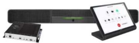
natural_image
Product photo of a network equipment setup including a server, remote control unit, and tablet (no visible text or symbols)
natural_image
Exterior view of a server rack and connected device (no visible text or symbols)UC-BX31-Z / UC-BX31-Z-INDIA UC-BX31-Z-WM / UC-BX31-Z-WM-INDIA
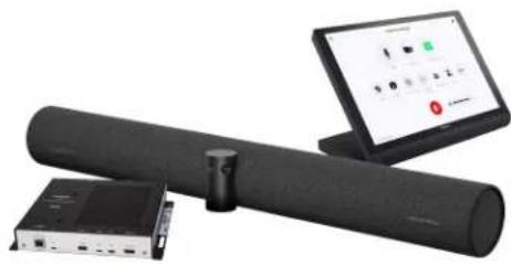
natural_image
Three electronic devices: a cylindrical network device, a connected network switch, and a laptop displaying a control interface (no visible text or symbols)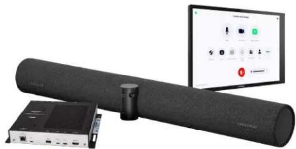
natural_image
Product photo of a black audio/video streaming device with a monitor displaying app icons and a small electronic device nearby (no visible text or symbols on main components)Included Components
| UC-BX30-Z | UC-BX31-Z(-INDIA) | UC-BX30-Z-WM | UC-BX31-Z-WM(-INDIA) | |
| UC-SB1-CAM-FLEX | √ | ✗ | √ | √ |
| UC-SB-P50 or UC-SB-P50-INDIA | ✗ | √ | ✗ | √ |
| TS-1070-B-S | √ | √ | ✗ | ✗ |
| TSW-1070-B-S | ✗ | ✗ | √ | √ |
| UC-BRKT-260-P-Z-ASSY | √ | √ | √ | √ |
| UC-PR with Cable Organizer | √ | √ | √ | √ |
| Cables | √ | √ | √ | √ |
To view the specifications and dimensions of the included components of the selected kit, refer to Specifications and Dimension Drawings.
Key Features
- Front-of-room video conferencing solution for Zoom Rooms software
- Native Zoom Rooms touch screen UI provides a consistent user experience with simple operation and one-touch meeting joins
- Network management and provisioning and system alerts through the XiO Cloud® service
• Supports up to three video displays (not included) - Present, call, conference, and collaborate using your own device's UC conference platform (BYOD) or the native Zoom Rooms platform
- Easy to specify and install — no custom design, programming, or software installation required
- Enterprise-grade security — connects and communicates securely over any enterprise or SMB network
- Premium-level support with Crestron Flex Care (optional)
Native Zoom Rooms Software Experience
The conferencing solution features Zoom Rooms conferencing software that enables audio and video connectivity for easy collaboration and content sharing.
Intuitive User Interface
With a large 10.1 in. (257 mm) capacitive touch screen display, the Crestron tabletop or wall mount touch scree provides superior conferencing control in meeting rooms, huddle spaces, and executive offices.
Using the bracket provided with the wall mount touch screen, the touch screen is easily installed over a 2-gang or 3-gang US electrical box, or a 2-gang European or UK electrical box. A security latch option is included to deter unauthorized removal of the touch screen.
Simplified Deployment
The UC Bracket Assembly provides preassembled components on one ready-to-mount bracket to simplify installation. The assembly can be mounted on a wall, or it can be attached to the rear of the display device.
High-Definition Video Conferencing with Impressive Audio
UC-SB1-CAM-FLEX: High-quality speakers, microphone, and digital signal processing deliver exceptional full-duplex speakerphone performance from the Crestron UC video conference soundbar and camera (UC-SB1-CAM-FLEX). The built-in conferencing camera captures the room in HD 1080p video resolution and with an ultra-wide 150° diagonal field of view.
UC-SB-P50 or UC-SB-P50-INDIA: High-quality speakers and microphones deliver exceptional full-duplex performance from the Jabra PanaCast 50 video bar for Crestron Flex systems (UC-SB-P50 or UC-SB-P50-INDIA). Three built-in conferencing cameras capture the room in panoramic 4K resolution with a seamless 180° horizontal field of view.
Visit jabra.com/panacast50 for more information on the Jabra PanaCast 50 video bar for Crestron Flex systems.
Bring Your Own Device
Conference room visitors can connect their laptop to the Crestron Flex system to use their own UC conference platform. The UC Presentation Transmitter (UC-PR) switches to the connected laptop's UC platform and returns to the native platform when disconnected. a list of BYOD tested devices on the UC-PR, refer to OLH Article 1000889.
Enterprise-Grade Security
Crestron Flex is an enterprise-grade solution that is ideally equipped for mass deployment throughout any sized corporate, university, medical, military, or government facility.
Easy Provisioning and Device Management
The XiO Cloud service is an IoT cloud based provisioning service (available separately) that enables installers and IT managers to deploy and manage thousands of devices easily. The XiO Cloud service allows for system alerts, network management and provisioning, and the pairing of a control device to the system's UC Engine. System updates are controlled by Windows software update.
Visit www.crestron.com/xiocloud for additional information.
Premium-Level Support
Crestron Flex Care is an optional subscription service that automatically renews annually, providing 24/7 live remote technical support, an extended five year warranty on Crestron hardware, expedited advance replacements, and a discounted rate for on-site support.
Visit www.crestron.com/flexcare for detailed terms and conditions and additional information.
Deployment Resources
View the Pre-Deployment Checklist on page 438 to help plan your Crestron Flex installation.
Notes:
- Display must support "Wake on Sync" and "Sleep on No Sync" functionality. Consult the display manufacturer's specifications or internal settings of the specific display.
- Room control capability (lighting, shades, thermostats, etc.) requires additional equipment and commissioning to be provided by a Crestron authorized integrator and/or programmer. Additional costs may apply.
- The UC-PR uses a USB-C 2.0 connection to provide content sharing, BYOD support, and charging for a user's device. Because USB-C supports multiple functions, device compatibility often varies. While some devices can accept power and data through the same USB-C connection, others cannot. The USB-C port on the UC-PR (labelled "USB") uses DisplayPort alternate mode for transporting video signals. Consult the connected device's user manual or manufacturer to ensure that the device supports DisplayPort alternate mode. Some devices that support DisplayPort alternate mode may not support device charging. For a list of tested devices, refer to OLH Article 1000889. USB-C transfer speeds may vary based on the connected device's processing speed, system configuration, the operating environment, and/or other factors. If the user's device does not support USB-C, then a combination of HDMI and USB B may be used for content sharing or BYOD functionality. For details, see Connections (UC-BX30-Z and UC-BX31-Z series).
UC-B70-A-Z and UC-B70-A-Z-I Features
The UC-B70-A-Z and UC-B70-A-Z-I Crestron Flex tabletop conferencing system provides a medium to large room video conference solution for use with Zoom Rooms® software. It simplifies the communications and collaboration needs with fewer components and maximum efficiency. The UC-B70-A-Z(-I) features a 10.1 in. tabletop touch screen, Crestron Videobar 70 with intelligent high-definition video and audio, a PoE injector, and cables. The UC-B70-A-Z(-I) also supports up to three video displays ^1 (not included).
The UC-B70-A-Z(-1) conferencing solution delivers a hassle-free setup and installation, better space utilization, a cleaner and visually appealing environment, easy collaboration and content sharing, and scalable deployment.
UC-B70-A-Z(-I)
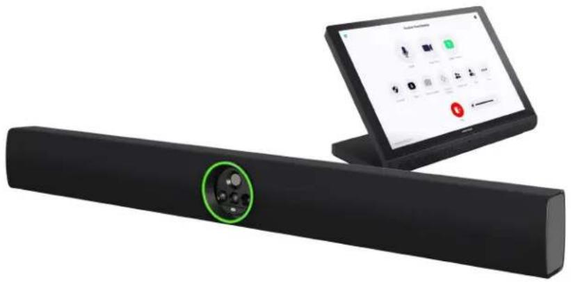
natural_image
Black electronic device with a green circular button on the left, next to a laptop displaying app icons (no readable text or symbols)Included Components
| UC-B70-A-Z | UC-B70-A-Z-I | |
| UC-SB2-CAM-A-Z | √ | √ |
| TS-1070-B-S | √ | √ |
| PoE Injector | √ | √ |
| Cables | √ | √ |
To view the specifications and dimensions of the included components of the selected kit, refer to Specifications and Dimension Drawings.
Key Features
- Front-of-room video conferencing solution for Zoom Rooms software
-
Intelligent high-definition video, immersive high-quality audio, built-in digital signal processor, and Zoom Rooms conferencing software, all in one Android™ OS-based Crestron Videobar 70 enclosure
-
Native Zoom Rooms Controller touch screen UI provides a consistent user experience with simple operation and one-touch meeting joins
- Easy to deploy and install — no custom design, programming, or software installation required
• Network management and provisioning and system alerts through the XiO Cloud service - Enterprise-grade security - connects and communicates securely over any enterprise or SMB network
• Supports up to three video displays (not included)
High-Definition Video Conferencing with Impressive Audio
The powerful and elegant all-in-one (AIO) Crestron Videobar 70 provides a convenient and compact conferencing solution for medium to large-sized meeting rooms. It comprises:
- A quad-camera setup that captures the full room in 4K, automatically tracks and frames the presenter or everyone in the room based on its configuration, and enhances the video content using AI.
- 10-watt dual speakers produce full, rich, and natural-sounding audio. Additional digital signal processing with AEC and noise reduction assures optimal sound quality for an immersive experience.
- Integrated 24-microphone array to capture voices throughout the room using adaptive beamforming technology. AI noise cancellation is also provided to ensure crystal-clear communication with exceptional audio fidelity and pickup.
- Android™ OS running on the QCS8250 chipset that ensures a smooth and reliable conferencing experience every time.
Native Zoom Rooms Software Experience
The conferencing solution features Zoom Rooms conferencing software that enables audio and video connectivity for easy collaboration and content sharing.
Android™ OS-Based Conferencing System
As an Android OS-based conferencing system, the conferencing solution provides a consistent, secure Zoom Rooms® experience. The system's tabletop controller and Videobar 70 both run on Android OS to ensure compliance with enterprise requirements.
Intuitive User Interface
With a large 10.1 in. (257 mm) capacitive touch screen display, the Crestron tabletop touch screen provides superior conferencing control in meeting rooms, huddle spaces, and executive offices. The touch screen also offers optional control of room lighting, shades, thermostats, and other equipment.
Simplified Deployment
The AIO Crestron Videobar 70 comes with one ready-to-mount wall bracket allowing the video bar to install cleanly beneath the display - connect the displays and touch screen and mount.
Enterprise-Grade Security
Crestron Flex is an enterprise-grade solution that is ideally equipped for mass deployment throughout any sized corporate, university, medical, military, or government facility.
Easy Provisioning and Device Management
The XiO Cloud service is an IoT cloud based provisioning service (available separately) that enables installers and IT managers to deploy and manage thousands of devices easily. The XiO Cloud service allows for system alerts, network management and provisioning, and the pairing of a control device to the system's UC Engine. System updates are controlled by Windows software update.
Visit www.crestron.com/xiocloud for additional information.
Notes:
- Display must support "Wake on Sync" and "Sleep on No Sync" functionality. Consult the display manufacturer's specifications or internal settings of the specific display.
- Room control capability (lighting, shades, thermostats, etc.) requires additional equipment and commissioning to be provided by a Crestron authorized integrator and/or programmer. Additional costs may apply.
UC-MM30-Z and UC-MMX30-Z Series Features
The UC-MM30-Z(-I) standard and UC-MMX30-Z(-I) advanced (with BYOD functionality) series Crestron Flex tabletop conferencing system provides a small room video conference solution for use with Zoom Rooms software. It supports single or dual video displays included).
UC-MM30-Z / UC-MM30-Z-I UC-MMX30-Z / UC-MMX30-Z-I
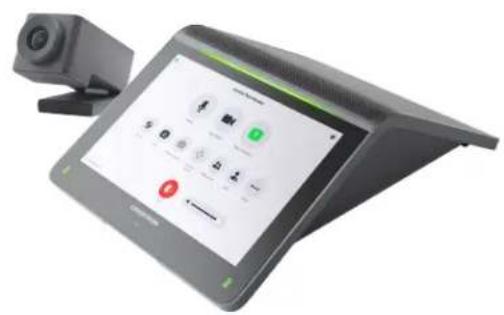
text_image
Tablet device with digital interface displaying control buttons and a camera on top, showing text and icons for phone call and navigation.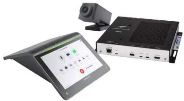
natural_image
Exterior view of a modern office building (no signage)Included Components
| UC-MM30-Z(-I) | UC-MMX30-Z(-I) | |
| UC-2 | √ | √ |
| CCS-CAM-USB-F-400 | √ | √ |
| UC-CAM-WMK | √ | √ |
| UC-BRKT-200-S-Z-ASSY | √ | ✗ |
| UC-BRKT-250-P-Z-ASSY or UC-BRKT-260-P-Z-ASSY | ✗ | √ |
| UC-PR with Cable Organizer | √ | √ |
| Cables | √ | √ |
To view the specifications and dimensions of the included components of the selected kit, refer to Specifications and Dimension Drawings.
Key Features
- Tabletop video conferencing solution for Zoom Rooms software
- Native Zoom Rooms touch screen UI provides a consistent user experience with simple operation and one-touch meeting joins
• Network management and provisioning and system alerts through the XiO Cloud service
• Supports up to three video displays (not included) -
With MMX30 series solutions — present, call, conference, and collaborate using your own device's UC conference platform (BYOD) or the native Zoom Rooms platform
-
Easy to specify and install — no custom design, programming, or software installation required
- Enterprise-grade security — connects and communicates securely over any enterprise or SMB network
- Premium-level support with Crestron Flex Care (optional)
Native Zoom Rooms Software Experience
The conferencing solution features Zoom Rooms conferencing software that enables audio and video connectivity for easy collaboration and content sharing.
Intuitive User Interface with Impressive Audio
With a large 7 in. HD color touch screen and an integrated AEC-enabled USB speakerphone that affords full-duplex wideband audio performance, the mini Crestron Flex Tabletop Conference device provides a superior conferencing and collaboration experience for meeting rooms, huddle spaces, and executive offices.
Simplified Deployment
The UC Bracket Assembly provides preassembled components on one ready-to-mount bracket to simplify installation. The assembly can be mounted on a wall, or it can be attached to the rear of the display device.
High-Definition Video Conferencing
The included collaboration camera (CCS-CAM-USB-F-400) features an ultra wide-angle 150° diagonal field of view to capture an entire conference room in Full HD 1080p video resolution. High precision aspherical optics, 12 MP CMOS sensor, and advanced video processing ensure a clear video image free from light or noise artifacts. Genius Framing digital autozoom detects the people in the room and frames them for an optimal view.
Bring Your Own Device (offered with MMX series solutions)
Conference room visitors can connect their laptop to the Crestron Flex system to use their own UC conference platform. The UC Presentation Transmitter (UC-PR) switches to the connected laptop's UC platform and returns to the native platform when disconnected. a list of BYOD tested devices on the UC-PR, refer to OLH Article 1000889.
Enterprise-Grade Security
Crestron Flex is an enterprise-grade solution that is ideally equipped for mass deployment throughout any sized corporate, university, medical, military, or government facility.
Easy Provisioning and Device Management
The XiO Cloud service is an IoT cloud based provisioning service (available separately) that enables installers and IT managers to deploy and manage thousands of devices easily. The XiO Cloud service allows for system alerts, network management and provisioning, and the pairing of a control device to the system's UC Engine. System updates are controlled by Windows software update.
Visit www.crestron.com/xiocloud for additional information.
Premium-Level Support
Crestron Flex Care is an optional subscription service that automatically renews annually, providing 24/7 live remote technical support, an extended five year warranty on Crestron hardware, expedited advance replacements, and a discounted rate for on-site support.
Visit www.crestron.com/flexcare for detailed terms and conditions and additional information.
Deployment Resources
View the Pre-Deployment Checklist on page 438 to help plan your Crestron Flex installation.
Notes:
- Display must support "Wake on Sync" and "Sleep on No Sync" functionality. Consult the display manufacturer's specifications or internal settings of the specific display.
- The UC-PR uses a USB-C 2.0 connection to provide content sharing, BYOD support, and charging for a user's device. Because USB-C supports multiple functions, device compatibility often varies. While some devices can accept power and data through the same USB-C connection, others cannot. The USB-C port on the UC-PR (labelled "USB") uses DisplayPort alternate mode for transporting video signals. Consult the connected device's user manual or manufacturer to ensure that the device supports DisplayPort alternate mode. Some devices that support DisplayPort alternate mode may not support device charging. For a list of tested devices, refer to OLH Article 1000889. USB-C transfer speeds may vary based on the connected device's processing speed, system configuration, the operating environment, and/or other factors. If the user's device does not support USB-C, then a combination of HDMI and USB B may be used for content sharing or BYOD functionality. For details, see Connections (UC-MMX30-Z).
UC-C100-Z and UC-CX100-Z Series Features
The UC-C100-Z standard and UC-CX100-Z advanced (with BYOD functionality) series Crestron Flex integrator kit provides a customizable video conference solution for use with Zoom Rooms software. It supports up to three video display (not included).
text_image
Charter Home Studio
text_image
Creative Team Standup Make Stop Video Share Content Quality View Switch Camera Camera Control Portable Invite More Endnatural_image
Two electronic devices: a black-and-white display screen and a black-and-white rack with ports and indicators (no visible text or symbols on main components)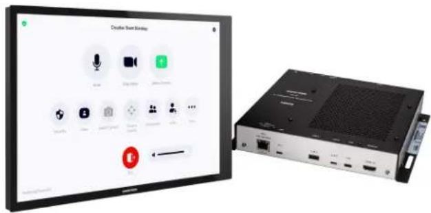
text_image
Creative Tree Monday Audio Box Audio Audio Audio Audio Audio Audio Audio Audio Audio Audio Audio Audio Audio Audio Audio Audio Audio Audio Audio Audio Audio Audio Audio Audio Audio Audio Audio Audio Audio Audio Audio Audio Audio Audio Audio Audio Audio Audio Audio Audio Audio Audio Audio Audio Audio Audio Audio Audio Audio Audio AuctionIncluded Components
| UC-C100-Z | UC-C100-Z-WM | UC-CX100-Z | UC-CX100-Z-WM | |
| TS-1070-B-S | √ | × | √ | × |
| TSW-1070-B-S | × | √ | × | √ |
| UC-BRKT-200-S-Z-ASSY | √ | √ | ✗ | ✗ |
| UC-BRKT-260-P-Z-ASSY | ✗ | ✗ | √ | √ |
| UC-PR with Cable Organizer | ✗ | ✗ | √ | √ |
| PoE Injector | √ | √ | ✗ | ✗ |
| Cables | √ | √ | √ | √ |
To view the specifications and dimensions of the included components of the selected kit, refer to Specifications and Dimension Drawings.
Key Features
• Conferencing integration solution for Zoom Rooms software
- Native Zoom Rooms touch screen UI provides a consistent user experience with simple operation and one-touch meeting joins
• Network management and provisioning and system alerts through the XiO Cloud service
• Supports up to three video displays (not included)
- With CX100 series solutions — Present, call, conference, and collaborate using your own device's UC conference platform (BYOD) or the native Zoom Rooms platform
- Enterprise-grade security — connects and communicates securely over any enterprise or SMB network
• Premium-level support with Crestron Flex Care (optional)
Native Zoom Rooms Software Experience
The conferencing solution features Zoom Rooms conferencing software that enables audio and video connectivity for easy collaboration and content sharing.
Custom Room Integration
The conferencing solution system provides the essential components needed to design a fully custom video conferencing space using your choice of display devices, cameras, speakers, microphones, and other AV equipment. Any Microsoft Teams software compliant USB camera and USB audio conferencing interface (or speakerphone) may be used.
Intuitive User Interface
With a large 10.1 in. (257 mm) capacitive touch screen display, the Crestron tabletop or wall mount touch scree provides superior conferencing control in meeting rooms, huddle spaces, and executive offices.
Using the bracket provided with the wall mount touch screen, the touch screen is easily installed over a 2-gang or 3-gang US electrical box, or a 2-gang European or UK electrical box. A security latch option is included to deter unauthorized removal of the touch screen.
Simplified Deployment
The UC Bracket Assembly provides preassembled components on one ready-to-mount bracket to simplify installation. The assembly can be mounted on a wall, or it can be attached to the rear of the display device.
Bring Your Own Device (offered with CX series solutions)
Conference room visitors can connect their laptop to the Crestron Flex system to use their own UC conference platform. The UC Presentation Transmitter (UC-PR) switches to the connected laptop's UC platform and returns to the native platform when disconnected. a list of BYOD tested devices on the UC-PR, refer to OLH Article 1000889.
Enterprise-Grade Security
Crestron Flex is an enterprise-grade solution that is ideally equipped for mass deployment throughout any sized corporate, university, medical, military, or government facility.
Easy Provisioning and Device Management
The XiO Cloud service is an IoT cloud based provisioning service (available separately) that enables installers and IT managers to deploy and manage thousands of devices easily. The XiO Cloud service allows for system alerts, network management and provisioning, and the pairing of a control device to the system's UC Engine. System updates are controlled by Windows software update.
Visit www.crestron.com/xiocloud for additional information.
Premium-Level Support
Crestron Flex Care is an optional subscription service that automatically renews annually, providing 24/7 live remote technical support, an extended five year warranty on Crestron hardware, expedited advance replacements, and a discounted rate for on-site support.
Visit www.crestron.com/flexcare for detailed terms and conditions and additional information.
Deployment Resources
View the Pre-Deployment Checklist on page 438 to help plan your Crestron Flex installation.
Notes:
- Display must support "Wake on Sync" and "Sleep on No Sync" functionality. Consult the display manufacturer's specifications or internal settings of the specific display.
- The UC-PR uses a USB-C 2.0 connection to provide content sharing, BYOD support, and charging for a user's device. Because USB-C supports multiple functions, device compatibility often varies. While some devices can accept power and data through the same USB-C connection, others cannot. The USB-C port on the UC-PR (labelled "USB") uses DisplayPort alternate mode for transporting video signals. Consult the connected device's user manual or manufacturer to ensure that the device supports DisplayPort alternate mode. Some devices that support DisplayPort alternate mode may not support device charging. For a list of tested devices, refer to OLH Article 1000889. USB-C transfer speeds may vary based on the connected device's processing speed, system configuration, the operating environment, and/or other factors. If the user's device does not support USB-C, then a combination of HDMI and USB B may be used for content sharing or BYOD functionality. For details, see Connections (UC-CX100-Z).
UC-M50-Z and UC-MX50-Z Features
The UC-M50-Z standard and UC-MX50-Z advanced (with BYOD functionality) series Crestron Flex tabletop conferencing system provides a medium room video conference solution for use with Zoom Rooms software. It supports up to three video displays included).
UC-M50-Z UC-MX50-Z
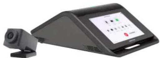
natural_image
Exterior view of a black rectangular electronic device with a camera lens and display screen (no visible text or symbols)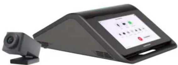
natural_image
Exterior view of a black digital camera module with a screen displaying a green control panel (no visible text or symbols)Included Components
| UC-M50-Z | UC-MX50-Z | |
| CCS-UC-1 | √ | ✗ |
| CCS-UC-1-X | ✗ | √ |
| CCS-CAM-USB-F-400 | √ | √ |
| UC-CAM-WMK | √ | √ |
| PW-2420RU | √ | ✗ |
| UC-BRKT-200-S-Z-ASSY | √ | ✗ |
| UC-BRKT-250-P-Z-ASSY or UC-BRKT-260-P-Z-ASSY | ✗ | √ |
| Cables | √ | √ |
To view the specifications and dimensions of the included components of the selected kit, refer to Specifications and Dimension Drawings.
Key Features
• Tabletop video conferencing solution for Zoom Rooms environment
- Native Zoom Rooms touch screen UI provides a consistent user experience with simple operation and one-touch meeting joins
• Network management and provisioning and system alerts through the XiO Cloud service
• Supports single or dual video displays (not included)
- With MX50 series solutions — present, call, conference, and collaborate using your own device's UC conference platform (BYOD) or the native Zoom Rooms platform
- Easy to specify and install — no custom design, programming, or software installation required
- Enterprise-grade security — connects and communicates securely over any enterprise or SMB network
- Premium-level support with Crestron Flex Care (optional)
Native Zoom Rooms Software Experience
The conferencing solution features Zoom Rooms conferencing software that enables audio and video connectivity for easy collaboration and content sharing.
Intuitive User Interface with Impressive Audio
With a large 7 in. HD color touch screen and an integrated AEC-enabled USB speakerphone that affords full-duplex wideband audio performance, the Crestron Flex Tabletop Conference device provides a superior conferencing and collaboration experience for meeting rooms, huddle spaces, and executive offices.
Simplified Deployment
The UC Bracket Assembly provides preassembled components on one ready-to-mount bracket to simplify installation. The assembly can be mounted on a wall, or it can be attached to the rear of the display device.
High-Definition Video Conferencing
The included collaboration camera (CCS-CAM-USB-F-400) features an ultra wide-angle 150° diagonal field of view to capture an entire conference room in Full HD 1080p video resolution. High precision aspherical optics, 12 MP CMOS sensor, and advanced video processing ensure a clear video image free from light or noise artifacts. Genius Framing digital autozoom detects the people in the room and frames them for an optimal view.
Bring Your Own Device (offered with MX series solutions)
Conference room visitors can connect their laptop to the Crestron Flex system to use their own UC conference platform. The system's built-in content ingest device switches to the connected laptop's UC platform and returns to the native platform when disconnected.
Enterprise-Grade Security
Crestron Flex is an enterprise-grade solution that is ideally equipped for mass deployment throughout any sized corporate, university, medical, military, or government facility.
Easy Provisioning and Device Management
The XiO Cloud service is an IoT cloud based provisioning service (available separately) that enables installers and IT managers to deploy and manage thousands of devices easily. The XiO Cloud service allows for system alerts, network management and provisioning, and the pairing of a control device to the system's UC Engine. System updates are controlled by Windows software update.
Visit www.crestron.com/xiocloud for additional information.
Premium-Level Support
Crestron Flex Care is an optional subscription service that automatically renews annually, providing 24/7 live remote technical support, an extended five year warranty on Crestron hardware, expedited advance replacements, and a discounted rate for on-site support.
Visit www.crestron.com/flexcare for detailed terms and conditions and additional information.
Deployment Resources
View the Pre-Deployment Checklist on page 438 to help plan your Crestron Flex installation.
Note:
- Display must support "Wake on Sync" and "Sleep on No Sync" functionality. Consult the display manufacturer's specifications or internal settings of the specific display.
UC-M50-Z-UPGRD and UC-MX50-Z-UPGRD Features
The UC-M50-Z-UPGRD standard and UC-MX50-Z-UPGRD solution provides all of the necessary components to upgrade a deployed Crestron Flex tabletop conference device and camera to a complete video conference system for use with the Zoom Rooms software. It supports single or dual video displays ^1 .
natural_image
Front view of an electronic device panel with a black OCREON HCM sensor module and cables (no readable text or symbols on main components)
natural_image
Front view of a black industrial control panel with connected cables and a central power supply unit (no visible text or symbols)Included Components
| UC-M50-Z-UPGRD | UC-MX50-Z-UPGRD | |
| UC-BRKT-200-S-Z-ASSY | √ | ✗ |
| UC-BRKT-250-P-Z-ASSY or UC-BRKT-260-P-Z-ASSY | ✗ | √ |
| Cables | √ | √ |
To view the specifications and dimensions of the included components of the selected kit, refer to Specifications and Dimension Drawings.
Key Features
- Upgrades a single Crestron Flex tabletop conference device to a complete video conference system
-
Native Zoom Rooms software provides a consistent user experience with simple operation and one-touch meeting joins
• Network management and provisioning and system alerts through the XiO Cloud service
• Supports single or dual video displays -
With MX50 upgrade series solutions — present, call, conference, and collaborate using your own device's UC conference platform (BYOD) or the native Zoom Rooms platform
- Easy to specify and install — no custom design, programming, or software installation required
- Enterprise-grade security — connects and communicates securely over any enterprise or SMB network
- Premium-level support with Crestron Flex Care (optional)
Native Zoom Rooms Software Experience
The conferencing solution features Zoom Rooms conferencing software that enables audio and video connectivity for easy collaboration and content sharing.
Bring Your Own Device (offered with MX series solutions)
Conference room visitors can connect their laptop to the Crestron Flex system to use their own UC conference platform. The system's built-in content ingest device switches to the connected laptop's UC platform and returns to the native platform when disconnected.
Simplified Deployment
The UC Bracket Assembly provides preassembled components on one ready-to-mount bracket to simplify installation. The assembly can be mounted on a wall, or it can be attached to the rear of the display device.
Enterprise-Grade Security
Crestron Flex is an enterprise-grade solution that is ideally equipped for mass deployment throughout any sized corporate, university, medical, military, or government facility.
Easy Provisioning and Device Management
The XiO Cloud service is an IoT cloud based provisioning service (available separately) that enables installers and IT managers to deploy and manage thousands of devices easily. The XiO Cloud service allows for system alerts, network management and provisioning, and the pairing of a control device to the system's UC Engine. System updates are controlled by Windows software update.
Visit www.crestron.com/xiocloud for additional information.
Premium-Level Support
Crestron Flex Care is an optional subscription service that automatically renews annually, providing 24/7 live remote technical support, an extended five year warranty on Crestron hardware, expedited advance replacements, and a discounted rate for on-site support.
Visit www.crestron.com/flexcare for detailed terms and conditions and additional information.
Deployment Resources
View the Pre-Deployment Checklist on page 438 to help plan your Crestron Flex installation.
Note:
- Display must support "Wake on Sync" and "Sleep on No Sync" functionality. Consult the display manufacturer's specifications or internal settings of the specific display.
UC-M70-Z and UC-MX70-Z Features
The UC-M70-Z standard and UC-MX70-Z advanced (with BYOD functionality) Crestron Flex advanced tabletop conferencing system provides a large room video conference solution for use with Zoom Rooms software. It supports single or dual video display (not included).
UC-M70-Z UC-MX70-Z
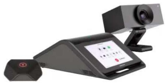
natural_image
Exterior view of a modern office building (no signage)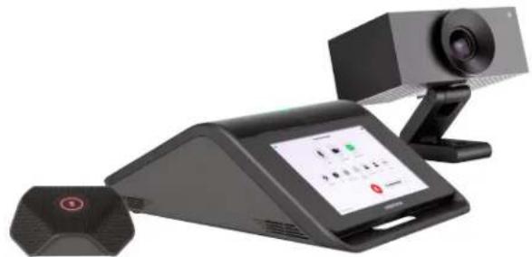
natural_image
Black desktop computer with a video camera and antenna, no visible text or symbols on the device itself.Included Components
| UC-M70-Z | UC-MX70-Z | |
| CCS-UC-1 | √ | ✗ |
| CCS-UC-1-X | ✗ | √ |
| UC-CAM-L1 | √ | √ |
| CCS-UCA-MIC | √ | √ |
| PW-2420RU | √ | ✗ |
| UC-BRKT-200-S-Z-ASSY | √ | ✗ |
| UC-BRKT-250-P-Z-ASSY or UC-BRKT-260-P-Z-ASSY | ✗ | √ |
| Cables | √ | √ |
To view the specifications and dimensions of the included components of the selected kit, refer to Specifications and Dimension Drawings.
Key Features
- Tabletop video conferencing solution for Zoom Rooms environment
- Native Zoom Rooms touch screen UI provides a consistent user experience with simple operation and one-touch meeting joins
• Network management and provisioning and system alerts through the XiO Cloud service
• Supports single or dual video displays (not included) -
With MX70 series solutions — present, call, conference, and collaborate using your own device's UC conference platform (BYOD) or the native Zoom Rooms platform
-
Easy to specify and install — no custom design, programming, or software installation required
- Enterprise-grade security — connects and communicates securely over any enterprise or SMB network
- Premium-level support with Crestron Flex Care (optional)
Native Zoom Rooms Software Experience
The conferencing solution features Zoom Rooms conferencing software that enables audio and video connectivity for easy collaboration and content sharing.
Intuitive User Interface with Impressive Audio
With a large 7 in. HD color touch screen and an integrated AEC-enabled USB speakerphone that affords full-duplex wideband audio performance, the Crestron Flex Tabletop Conference device provides a superior conferencing and collaboration experience for meeting rooms, huddle spaces, and executive offices.
Simplified Deployment
The UC Bracket Assembly provides preassembled components on one ready-to-mount bracket to simplify installation. The assembly can be mounted on a wall, or it can be attached to the rear of the display device.
High-Definition Video Conferencing
The included AI collaboration camera (UC-CAM ^2 features a wide-angle 103° diagonal field of view to capture an entire conference room in Full HD 1080p video resolution. High precision aspherical optics, 20.30 MP CMOS sensor, and advanced video processing ensure a clear video image free from light or noise artifacts. Genius Framing digital autozoom intelligently detects the people in the room and frames them for an optimal view.
Bring Your Own Device (offered with MX series solutions)
Conference room visitors can connect their laptop to the Crestron Flex system to use their own UC conference platform. The system's built-in content ingest device switches to the connected laptop's UC platform and returns to the native platform when disconnected.
Enterprise-Grade Security
Crestron Flex is an enterprise-grade solution that is ideally equipped for mass deployment throughout any sized corporate, university, medical, military, or government facility.
Easy Provisioning and Device Management
The XiO Cloud service is an IoT cloud based provisioning service (available separately) that enables installers and IT managers to deploy and manage thousands of devices easily. The XiO Cloud service allows for system alerts, network management and provisioning, and the pairing of a control device to the system's UC Engine. System updates are controlled by Windows software update.
Visit www.crestron.com/xiocloud for additional information.
Premium-Level Support
Crestron Flex Care is an optional subscription service that automatically renews annually, providing 24/7 live remote technical support, an extended five year warranty on Crestron hardware, expedited advance replacements, and a discounted rate for on-site support.
Visit www.crestron.com/flexcare for detailed terms and conditions and additional information.
Deployment Resources
View the Pre-Deployment Checklist on page 438 to help plan your Crestron Flex installation.
Notes:
- Display must support "Wake on Sync" and "Sleep on No Sync" functionality. Consult the display manufacturer's specifications or internal settings of the specific display.
- Applicable for UC-MX70-Z: The UC-CAM-L1 with network adapter requires driver installation on the connected laptop. A USB plug-and-play adapter, UC-CAMA-ADPT-ENET-USB, can be purchased separately to avoid driver installation.
UC-M70-NC-Z and UC-MX70-NC-Z Features
The UC-M70-NC-Z standard and UC-MX70-NC-Z advanced (with BYOD functionality) Crestron Flex advanced tabletop conferencing system provides a large room video conference solution for use with Zoom Rooms software. It supports single or dual video displays included).
UC-M70-NC-Z UC-MX70-NC-Z
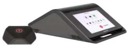
natural_image
Exterior view of a modern office building (no signage)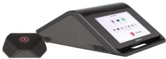
natural_image
Black electronic device with a digital display and a connected sensor (no visible text or symbols)Included Components
| UC-M70-NC-Z | UC-MX70-NC-Z | |
| CCS-UC-1 | √ | ✕ |
| CCS-UC-1-X | ✕ | √ |
| CCS-UCA-MIC | √ | √ |
| PW-2420RU | √ | ✕ |
| UC-BRKT-200-S-Z-ASSY | √ | ✕ |
| UC-BRKT-250-P-Z-ASSY or UC-BRKT-260-P-Z-ASSY | ✕ | √ |
| Cables | √ | √ |
To view the specifications and dimensions of the included components of the selected kit, refer to Specifications and Dimension Drawings.
Key Features
• Supports single or dual video displays (not included)
- With MX70 series solutions — present, call, conference, and collaborate using your own device's UC conference platform (BYOD) or the native Zoom Rooms platform
- Enterprise-grade security — connects and communicates securely over any enterprise or SMB network
• Premium-level support with Crestron Flex Care (optional)
Native Zoom Rooms Software Experience
The conferencing solution features Zoom Rooms conferencing software that enables audio and video connectivity for easy collaboration and content sharing.
Intuitive User Interface with Impressive Audio
With a large 7 in. HD color touch screen and an integrated AEC-enabled USB speakerphone that affords full-duplex wideband audio performance, the Crestron Flex Tabletop Conference device provides a superior conferencing and collaboration experience for meeting rooms, huddle spaces, and executive offices.
Simplified Deployment
The UC Bracket Assembly provides preassembled components on one ready-to-mount bracket to simplify installation. The assembly can be mounted on a wall, or it can be attached to the rear of the display device.
High-Definition Video Conferencing
High-definition video conferencing can be achieved by utilizing Zoom Rooms certified third-party cameras.
Bring Your Own Device (offered with MX series solutions)
Conference room visitors can connect their laptop to the Crestron Flex system to use their own UC conference platform. The system's built-in content ingest device switches to the connected laptop's UC platform and returns to the native platform when disconnected.
Enterprise-Grade Security
Crestron Flex is an enterprise-grade solution that is ideally equipped for mass deployment throughout any sized corporate, university, medical, military, or government facility.
Easy Provisioning and Device Management
The XiO Cloud service is an IoT cloud based provisioning service (available separately) that enables installers and IT managers to deploy and manage thousands of devices easily. The XiO Cloud service allows for system alerts, network management and provisioning, and the pairing of a control device to the system's UC Engine. System updates are controlled by Windows software update.
Visit www.crestron.com/xiocloud for additional information.
Premium-Level Support
Crestron Flex Care is an optional subscription service that automatically renews annually, providing 24/7 live remote technical support, an extended five year warranty on Crestron hardware, expedited advance replacements, and a discounted rate for on-site support.
Visit www.crestron.com/flexcare for detailed terms and conditions and additional information.
Deployment Resources
View the Pre-Deployment Checklist on page 438 to help plan your Crestron Flex installation.
Note:
- Display must support "Wake on Sync" and "Sleep on No Sync" functionality. Consult the display manufacturer's specifications or internal settings of the specific display.
Specifications and Dimension Drawings
Refer to the following sections for more information regarding the specifications and dimensions of the following devices.
Tabletop Conferencing Device Specifications
Device name: CCS-UC-1 / CCS-UC-1-X
Touch Screen 7 in. (178 mm) diagonal capacitive multi-touch TFT active matrix color LCD, 1280 x 800 pixels
UI Zoom Rooms UI
Mic Mute Symbol and Light Bar (2) Capacitive buttons with bi-color LEDs, either button toggles between mute and unmute
AEC Limes Audio TrueVoice® acoustic echo cancellation, automatic mic mixing, automatic gain control, and dynamic noise reduction, full-duplex IEEE 1329 Type 1 compliant
Speaker Full range speaker;
Amplifier Power: 11 W; 95 dB SPL at 0.5 m maximum output; Frequency Response: 90 Hz to 22 kHz
Microphones 360° quad mic array;
Pickup Range (typical): 20 ft (6 m)
Extension Microphones Supports two mic pods, model CCS-UCA-MIC (sold separately)
Occupancy Sensor 6 ft (1.83 m) PIR range in front of touch screen
Ethernet (CCS-UC-1) Dual-port 100 Mbps, auto-switching, auto-negotiating, auto-discovery, full/half duplex, DHCP, TCP/IP, UDP/IP, CIP, SSL, TLS, SSH, SFTP (SSH File Transfer Protocol), SRTP, IEEE 802.1X, Active Directory® authentication, LDAP, Kerberos, digest access authentication, password login, HTTPS secure provisioning, XiO Cloud client, primary port is IEEE 802.3at Type 2 PoE+ compliant
Ethernet (CCS-UC-1-TV) 100 Mbps, auto-switching, auto-negotiating, auto-discovery, full/half duplex, DHCP, TCP/IP, UDP/IP, CIP, SSL, TLS, SSH, SFTP (SSH File Transfer Protocol), SRTP, IEEE 802.1X, Active Directory authentication, digest access authentication, password login, XiO Cloud client, Microsoft Intune® client, IEEE 802.3at Type 2 PoE+ compliant
Ethernet (CCS-UC-1-X, CCS-UC-1-X-T-V) 100 Mbps, auto-switching, autonegotiating, autodiscovery, full/half duplex, DHCP, TCP/IP, UDP/IP, CIP, SSL, TLS, SSH, SFTP (SSH File Transfer Protocol), SRTP, IEEE 802.1X, Active Directory authentication, digest access authentication, password login, XiO Cloud service, Microsoft Intune® client
USB USB 2.0 micro Type B device port, supports UAC for audio interface to UC Engine (cable included)
Power Options (CCS-UC-PoE+: IEEE 802.3at Type 2, Class 4 (25.5 W) PoE+ Powered Device 1)
NOTE: If the additional mic pod (CCS-UCA-MIC) is used, PoE+ cannot be used to power the device.
24VDC: 24VDC via external 100-240VAC, 50/60 Hz power pack, model PW-2420RU
Power (CCS-UC-1-X) 24VDC via external 100-240VAC, 50/60 Hz power pack, model PW-2420RU
NOTE: The CCS-UC-1-X cannot be powered by Power over Ethernet or PoE+.
Dimensions Height: 4.11 in. (104 mm)
Width: 8.92 in. (227 mm)
Depth: 12.74 in. (324 mm)
Tabletop Conferencing Device Dimension Drawing

text_image
12.74 in. (324 mm)
natural_image
Technical line drawing of a mechanical component with no visible text or symbols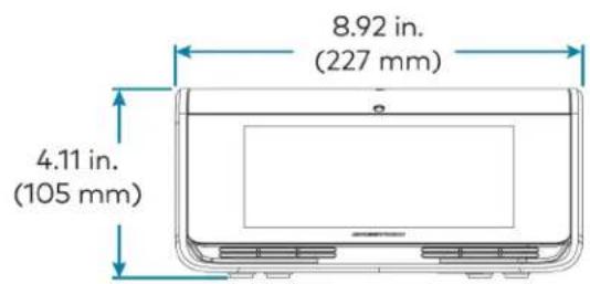
text_image
8.92 in. (227 mm) 4.11 in. (105 mm)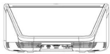
natural_image
Technical line drawing of a U-shaped mechanical component with mounting holes and internal channels (no text or symbols)Mini Tabletop Conferencing Device Specifications
Device name: UC-2-Z
Touch Screen 7 in. (178 mm) diagonal capacitive multi-touch TFT active matrix color LCD, 1280 x 800 pixels
UI Zoom Rooms UI
Mic Mute Symbol and (4) Capacitive buttons with bi-color LEDs, toggles between mute and unmute Light Bar
AEC Automatic gain control, dynamic noise reduction, acoustic echo cancellation, full-duplex IEEE 1329 Type 1 compliant
Speaker Full range speaker;
Amplifier Power: 7 W (rated power);
Output Volume: 83 ±3 dBA @1m 1 kHz;
Frequency Response: 100 Hz - 20 kHz
Microphones (4) Built-in omnidirectional, digital MEMS microphones with 360° audio pickup; Maximum pickup range: 10 ft (3 m) typical
Occupancy Sensor Approx. 10 ft (3 m) PIR range in front of touch screen
Ethernet 100 Mbps, auto-switching, auto-negotiating, auto-discovery, full/half duplex, DHCP, TCP/IP, UDP/IP, CIP, SSL, TLS, SSH, SFTP (SSH File Transfer Protocol), SRTP, IEEE 802.1X, Active Directory® authentication, digest access authentication, password login, XiO Cloud client, Microsoft Intune® client, IEEE 802.3at Type 2 PoE+ compliant
USB USB 2.0 micro Type B device port, supports UAC for audio interface to UC Engine (cable included)
Power IEEE 802.3af Class 3 and 802.3at Class 4 PoE+ powered device; PoE+ injector included
Dimensions Height: 3.02 in. (77 mm) Width: 7.17 in. (182 mm) Depth: 9.61 in. (244 mm)
Weight 2.1 lb (0.96 kg)
Mini Tabletop Conferencing Device Dimension Drawing
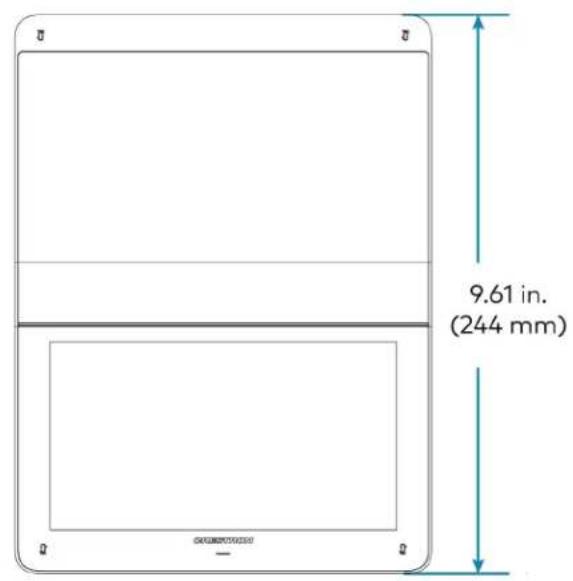
text_image
9.61 in. (244 mm)
text_image
7.17 in. (182 mm) 3.02 in. (76 mm)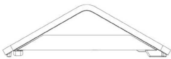
natural_image
Technical line drawing of a symmetrical structural component (no text or symbols)Tabletop and Wall Mount Touch Screen Specifications
Device name: TS-1070-B-S / TSW-1070-B-S
Touch Screen 10.1 in. (257 mm) diagonal capacitive multi-touch TFT active matrix color LCD, 1920 x 1200 pixels
UI Zoom Rooms UI plus optional Crestron Smart Graphics® room control UI 2
Ethernet 100/1000 Mbps, auto switching, auto negotiating, auto discovery, full/half duplex, TCP/IP, UDP/IP, CIP, DHCP, SSL, TLS, SSH, SFTP (SSH File Transfer Protocol), IEEE 802.1X, SNMP, IPv4 or IPv6, Active Directory® service authentication, HTTPS web browser setup, XiO Cloud® client, IEEE 802.3at compliant
Power over Ethernet IEEE 802.3at Type 2 compliant PoE+ PD (Powered Device); Normally requests 15 W from an 802.3at Type 2 PSE with LLDP advanced power management; With room scheduling and USB enabled, requests 18 W from an 802.3at Type 2 PSE with LLDP; Requests 30 W (PoE+ Class 4) from an 802.3at Type 2 PSE without LLDP; Requests 15.4 W (PoE Class 0) from an 802.3af (or 802.3at Type 1) PSE
Power Powered via PoE passthrough on the UC-PR
Construction Plastic, smooth black finish, edge-to-edge glass with black surround
Dimensions (TS-1070) Height: 5.29 in. (134 mm)
Width: 9.63 in. (245 mm)
Depth: 4.67 in. (119 mm)
Dimensions (TSW-1070) Height: 5.87 in. (149 mm)
Width: 9.46 in. (240 mm)
Depth: 2.01 in. (51 mm)
Dimensions do not include mounting bracket or add-on accessories
Weight (TS-1070) 2.44 lb (1105 g)
Weight (TSW-1070) 1.61 lb (730 g)
Tabletop Touch Screen Dimension Drawing
TS-1070-B-S

natural_image
Blank white rectangular frame with rounded corners and a thin border at the bottom (no text or symbols)
text_image
9.63 in. (245 mm) 9.56 in. (243 mm)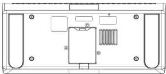
natural_image
Top-down schematic of a device rear panel with internal components and mounting holes (no text or labels)
text_image
5.29 in. (134 mm) 3.87 in. (98 mm) 4.67 in. (119 mm)Wall Mount Touch Screen Dimension Drawing
TSW-1070-B-S
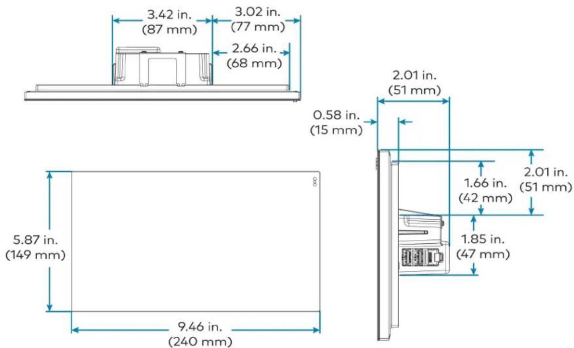
text_image
3.42 in. (87 mm) 3.02 in. (77 mm) 2.66 in. (68 mm) 0.58 in. (15 mm) 2.01 in. (51 mm) 5.87 in. (149 mm) 9.46 in. (240 mm) 1.66 in. (42 mm) 1.85 in. (47 mm) 2.01 in. (51 mm)Wall Mount Touch Screen Bracket Dimension Drawing
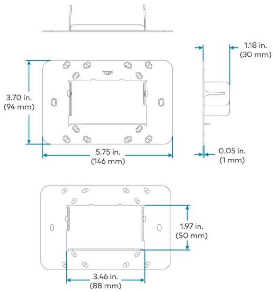
Crestron Videobar 70 Specifications
Speakers Dual 10-watt speakers, stereo;
Microphone 24 mic linear array
NOTE: Microphone pickup range may vary in rooms with highly reflective infrastructure (e.g., glass walls, metal furniture, open ceilings, etc.) or above average ambient noise.
Audio DSP Acoustic echo cancellation, dereverberation, automatic gain control, dynamic noise suppression, adaptive beamforming, speaker volume control, speaker EQ and limiting (fixed);
Quad Camera (1) Main camera;
Configuration (1) Left, (1) center, and (1) right sub cameras with 14^ overlap
Main Camera Optics Main camera 20 Megapixels 1 in. sensor
Camera Field of View Main Camera: 84.3° horizontal, 53.8° vertical;
Left, center and right sub cameras: 41° horizontal, 23° vertical
Camera Resolution Main Camera: 5472 x 3078 pixels;
Left, center and right sub camera: 3840 x 2160 pixels
Autozoom 7.5x digital zoom
Camera Shutter Mechanical, electronically controlled
Operating System Android OS running on the QCS8250 chipset
Memory LPDDR5 12GB;
UFS 128GB
Connectivity 100/1000 Mbps Ethernet connectivity
Wi-Fi® Connectivity Dual Band Simultaneous Wi-Fi 6 2x2 80 MHz
Bluetooth® Connectivity Bluetooth 5.2 (for future use)
UC Client Zoom Rooms software
Management Client XiO Cloud Service
Content Ingest HDMI input on Crestron Videobar 70 or direct sharing
Display Output Up to two displays support
Display Output Resolution (2) 4K
Video Input Signal Types HDMI, 1080p 30
Video Output Signal Types HDMI, 4K30
Video Content Protection HDCP 1.4 and HDCP 2.2
Audio Input Signal Types HDMI: Two-channel LPCM
Connectors HDMI port: (2) HDMI IN (Input 2 reserved for future use), (3) HDMI OUT (Output 3 reserved for future use);
3.5 mm Line in / Line out: (1) Audio In, (1) Audio Out (reserved for future use);
LAN: (2) 8-pin RJ-45 connector;
USB A: (2) USB 3.0 Type A connector (reserved for future use);
USB C: (2) USB 3.1 Type-C connector (reserved for future use)
Input Power 19VDC via external 100-240VAC, 50/60 Hz power pack (included)
Temperature 32° to 104°F (0° to 40°C)
Enclosure Plastic, smooth black finish;
Speaker and camera housing, rear air vents, integrated mounting bracket
LED Indicators Green indicates microphones are unmuted;
Red indicates microphones are muted
Mounting Wall mount using integrated mounting bracket, optional desktop stand and display bracket accessories
Dimensions Height: 4.33 in. (110 mm); 6.38 in. (162 mm) with bracket;
Length: 38.58 in. (980 mm)
Depth: 3.77 in. (96 mm); 4 in. (101 mm) with bracket
Weight 13.2 lb (6 kg)
Crestron Videobar 70 Dimension Drawing

text_image
3.77 in. (96 mm) 4 in. (101 mm)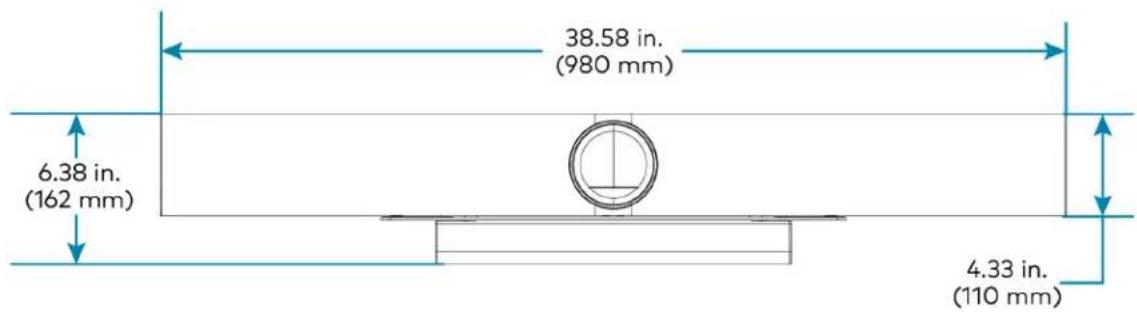
text_image
38.58 in. (980 mm) 6.38 in. (162 mm) 4.33 in. (110 mm)Smart Soundbar and Camera Specifications
UC-SB1-CAM-FLEX
| Speakers Stereo 2-way, 20 W per channel; |
| 3 in. (76 mm) woofers; |
| 3 x 4-3/8 in. (76 x 112 mm) passive radiators; |
| 1 in. (25 mm) dome tweeters; |
| 80 Hz to 20 kHz ( ± 3 dB) frequency response; |
| 91 dB SPL @ 1 m output level (both channels driven at full power) |
| Microphone Linear quad-element far-field adaptive beamforming microphone array;15 ft (4.6 m) pickup range, 180° horizontal and 180° vertical pickup angle;20 Hz to 8 kHz frequency response |
NOTE: Microphone pickup range may vary in rooms with highly reflective infrastructure (e.g., glass walls, metal furniture, open ceilings, etc.) or above average ambient noise.
| Audio DSP Acoustic echo cancellation, dereverberation, automatic gain control, dynamic noise suppression, adaptive beamforming, speaker volume control, speaker EQ and limiting (fixed);Full-duplex IEEE 1329 Type 1 compliant | |
| Camera Optics | 12 Megapixel 1/2.3 CMOS sensor, ultra wide angle six element aspherical glass lens,f/2.8 aperture |
| Camera Field of View 150° diagonal, 120° horizontal, 90° vertical | |
| Autozoom Genius Framing automatic lossless digital zoom intelligently frames around people in the room | |
| Camera Noise Reduction | 3D noise reduction, bias compensating spatio-temporal filtering, wide area chroma filtering, flicker elimination |
| Camera Scaling Real-time scaling, dewarping, and perspective correction | |
| Camera Resolution HD 1080p @ 30 fps | |
| Analog Audio Input | 2-Channel stereo via 3.5 mm TRS mini-phone jack, fixed level (bypasses DSP), 1 Vrms maximum per channel for full rated output, for in-room amplification of an external audio source |
| Analog Audio Output | 2-Channel stereo via 3.5 mm TRS mini-phone jack, fixed level, 1 Vrms maximum, feeds amplified audio content to an assistive listening system |
| Status Bar | Multi-segment RGBY LED zero-center mutually-diverging linear bargraph |
| Main Power | 24VDC via external 100-240VAC, 50/60 Hz power pack, model PW-2420RU (included) |
| Enclosure | Lightly textured gunmetal black finish, plastic housing, perforated stainless steel grilles, die-cast aluminum rear cover, integral steel hinged mounting bracket |
| Mounting | Freestanding or surface wall mount at ear/face level (adhesive feet included,mounting bracket attached) |
| Dimensions | Height: 4.57 in. (116 mm), 4.64 in. (118 mm) with feetWidth: 43.60 in. (1107 mm)Depth: 3.90 in. (99 mm) |
| Weight | 13.56 lb (6.2 kg) |
UC-SB1-CAM-FLEX Dimension Drawing

text_image
3.90 in (99 mm) 43.60 in (1107 mm) 4.57 in (116 mm) 6.82 in. (173 mm) 1.80 in. (46 mm) 1.24 in. (32 mm) 2.00 in (51 mm) (each) 12.00 in (305 mm) each 2.00 in (51 mm) (each) Connector Panel behind Mounting Bracket Connector PanelUC-SB-P50 or UC-SB-P50-INDIA
Speakers (4) speakers, stereo;
2 in. (50 mm) woofers;
2 x 3/4 in. (50 x 20 mm) tweeters;
80 Hz to 20 kHz frequency response;
Automatic speaker detection
Microphone (8) microphone beamforming array;
-37 dBFS microphone sensitivity;
100 Hz to 8 kHz microphone frequency range;
Suitable for rooms up to 15 x 15 ft (4.5 x 4.5 m)
NOTE: Microphone pickup range may vary in rooms with highly reflective infrastructure (e.g., glass walls, metal furniture, open ceilings, etc.) or above average ambient noise.
Camera Optics (3) cameras;
13 Megapixels
Camera Field of View 180° horizontal, 54° vertical
Autozoom Automatic digital zoom dynamically frames people within 11 ft (3.5 m)
Camera Resolution 3840 x 1080 @ 30 fps
Power From external power pack;
Input: 100-240VAC, 50/60 Hz;
Output: 5A @ 12V
Enclosure Black speaker and camera housing, rear air vents, integrated adjustable mounting bracket
Mounting Wall mount using integrated mounting bracket;
Optional table mount or VESA® compliant screen mount (both sold separately)
Dimensions Height: 3.1 in. (90 mm)
Width: 25.60 in. (650 mm)
Depth: 4.90 in. (125 mm)
Weight 4.85 lb (2.2 kg)
For more information on the Jabra PanaCast 50 video bar for Crestron Flex systems, refer to jabra.com/panacast50.
Camera Specifications
CCS-CAM-USB-F-400
Image Sensor 12 Megapixel 1/2.3 CMOS sensor
Lens High precision, ultra wide angle, six element aspherical glass lens
Field of View 150° diagonal, 120° horizontal, 90° vertical
Aperture f/2.8
Autozoom Genius Framing automatic lossless digital zoom intelligently frames around people in the room
Connectivity Plug-and-play USB 3.1
Resolution/FPS HD 1080p @ 30 fps
Dimensions Height: 1.40 in. (36 mm)
Width: 1.60 in. (41 mm)
Depth: 2.82 in. (72 mm)
Weight 4.2 oz (120 g)
UC-CAM-L1
Image Sensor 20.30 Megapixels 1 in. CMOS Sensor
Lens High precision, wide angle, aspherical glass lens
Field of View 103° diagonal, 92° horizontal, 65° vertical
Aperture f/2.9
Autozoom Genius Framing automatic lossless digital zoom intelligently frames around people in the room
Connectivity USB 3.0 port (via USB to PoE Adapter)
Power 5VDC power adapter
Resolution/FPS HD 1080p @ 30 fps
Dimensions Height: 2.1 in. (53 mm)
Width: 4.8 in. (122 mm)
Depth: 3.5 in. (89 mm)
Weight 1.3 lb (0.6 kg)
UC Engine Bracket Assembly Specifications
Device name: UC-BRKT-200-S-Z-ASSY / UC-BRKT-250-P-Z-ASSY / UC-BRKT-260-P-Z-ASSY
UC Engine Mini PC, Intel Core® processor with Windows® 10 IoT Edition OS and 100/1000 Mbps Ethernet connectivity
UC Client Zoom Rooms software
Management Client XiO Cloud Service
Content Ingest HDMI input via HDMI to USB 3.0 converter (UC-BRKT-200-S-Z-ASSY)
Content Ingest HDMI input via CAT5 to USB 3.0 converter (UC-BRKT-250-P-Z-ASSY or UC-BRKT-260-P-Z-ASSY)
NOTE: Use only DigitalMedia™ Ultra cable between the conference and content ingest devices (UC-BRKT-250-P-T-ASSY). The maximum supported cable length is 300 ft.
Display Output Up to three displays support
Display Output Resolution 1080p
Power (UC-BRKT-200-S-130 W via external 100-240VAC, 50/60 Hz adapter (included) Z-ASSY)
Power (UC-BRKT-250-P- UC Engine: 100-240VAC, 50/60 Hz adapter (included);
Z-ASSY / UC-BRKT-260-P-Z-ASSY) Content ingest device: 24VDC via external 100-240VAC, 50/60 Hz power pack (included)
Construction Metal mounting bracket, black, preassembled with UC Engine and content ingest device
Mounting Surface wall mount behind the display device, or attach to the rear of the display device via the bolts attaching the display to a VESA® compliant display mount; Bracket includes mounting holes on both side edges, spaced 100, 200, and 300 mm vertically, to allow for attachment to either side of the display mounting plate
Dimensions Maximum Height: 15.00 in. (381 mm)
Maximum Width: 14.50 in. (368 mm)
Maximum Depth: 1.93 in. (49 mm)
Maximum Weight 8.0 lb (3.7 kg)
UC Engine Bracket Assembly Dimension Drawing
UC-BRKT-200-S-Z-ASSY
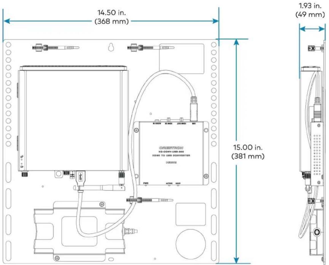
text_image
14.50 in. (368 mm) 1.93 in. (49 mm) 15.00 in. (381 mm)UC-BRKT-250-P-Z-ASSY
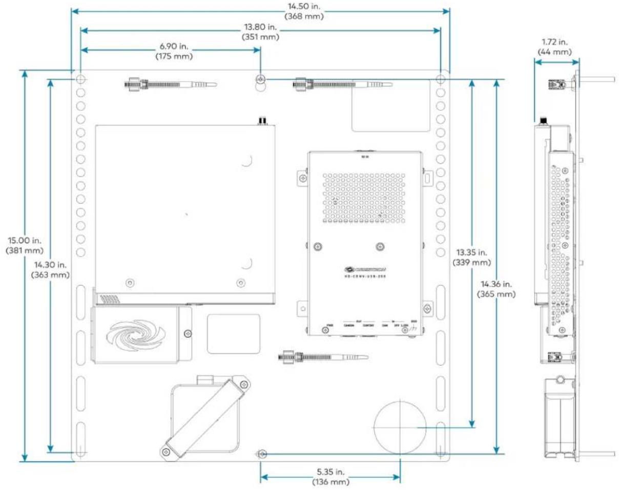
text_image
14.50 in. (368 mm) 13.80 in. (351 mm) 6.90 in. (175 mm) 15.00 in. (381 mm) 14.30 in. (363 mm) 13.35 in. (339 mm) 14.36 in. (365 mm) 5.35 in. (136 mm) 1.72 in. (44 mm)UC-BRKT-260-P-Z-ASSY

text_image
15.00 in. (381 mm) 14.50 in. (368 mm) 1.87 in. (48 mm)UC Presentation Transmitter Specifications
Video Input Signal Types HDMI, DisplayPort 1.2 via USB-C port
Video Output Signal Types HDMI over CAT5
Resolution 1080p
Video Content Protection HDCP 1.4 and HDCP 2.2
Audio Input Signal Types HDMI, DisplayPort 1.2 via USB-C port
Audio Output Signal Types HDMI over CAT5
Communications Ethernet: 100 Mbps, auto-switching, auto negotiating, auto-discovery
HDMI over CAT5: HDCP, Ethernet
HDMI: HDCP
USB: USB 2.0 and USB 3.0
Connectors LAN PoE: (1) 8-pin RJ-45 connector;
ACC: (1) USB 3.0 Type B connector;
For firmware loading only;
USB A: (1) USB 2.0 Type A connector;
USB B: (1) USB 2.0 Type B connector;
USB: (1) USB 2.0 Type-C connector;
HDMI IN: (1) HDMI Type A;
To RX: (1) 8-pin RJ-45 connector;
Power Jack: (1) DC power connector;
LAN: (1) 8-pin RJ-45 connector;
Ground: (1) 6-32 screw
Indicators PWR: (1) Green LED, indicates operating power supplied via power supply
Ethernet: (2) LEDs on To RX port;
Green indicates Ethernet link status;
Amber indicates Ethernet activity
Power Supply 24VDC, 6A, 100-240VAC
Device Charging Up to 60 W charging for devices connected via USB-C port
Construction Metal, black finish, integral mounting flanges;
Vented top, front, bottom, and sides
Mounting Surface mount for mounting under table;
Attaches to a single rack rail
Dimensions Height: 1.58 in. (40 mm)
Width: 9.25 in. (235 mm)
Depth: 8.20 in. (208 mm)
UC Presentation Transmitter Dimension Drawing

text_image
1.50 in. (38 mm) 1.58 in. (40 mm) 8.20 in. (208 mm) 8.37 in. (212 mm) 9.25 in. (235 mm)Microphone Pod Specifications
Model CCS-UCA-MIC
Communications A2B bus protocol, slave, synchronous data, multichannel I2S/TDM to I2S/TDM
Microphone Triple mic array with (3) cardioid electret elements
Pickup Range 20 ft (6 m) typical, 360°
Mic Mute (1) Capacitive button with bi-color LED, toggles between mute and unmute (affects all system mics)
Connectors (2) RJ9 4P4C connector, female
Power Powered via the conference device through the A2B bus
Dimensions Height: 0.97 in (25 mm)
Width: 3.81 in (97 mm)
Depth: 3.42 in (87 mm)
Microphone Pod Dimension Drawing

Installation and Connections
Refer to the following instructions to correctly install and connect various Zoom Rooms solutions.
To install and connect B30/BX30, C100/CX100, MM30/MMX30, M50/MX50, and M70/MX70 series solutions powered by the UC Engine (mini PC attached to the UC Engine Bracket Assembly):
- Identify the UC Engine model included with your Crestron Flex solution.
NOTE: The UC Engine is available in various models. Therefore, identify the included UC Engine model before installing the selected room solution and making system connections.
- Dell UC Engine
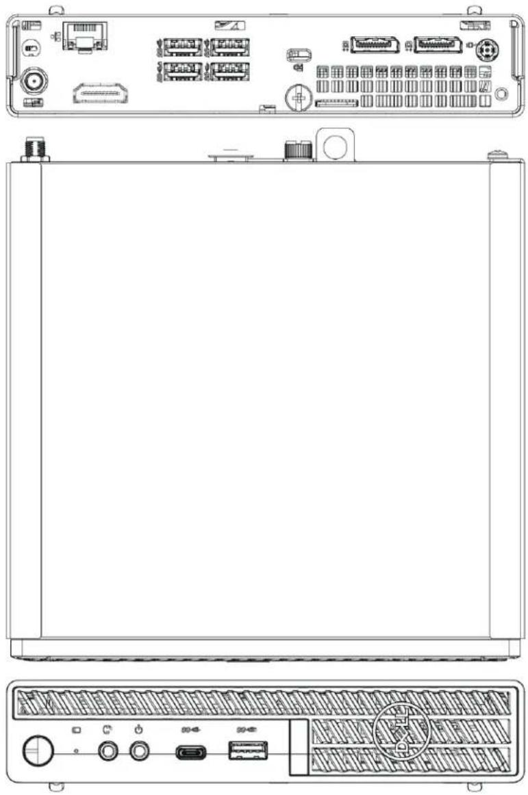
natural_image
Technical line drawing of a server rack front panel with ports, connectors, and control buttons (no text or labels)- ASUS UC Engine
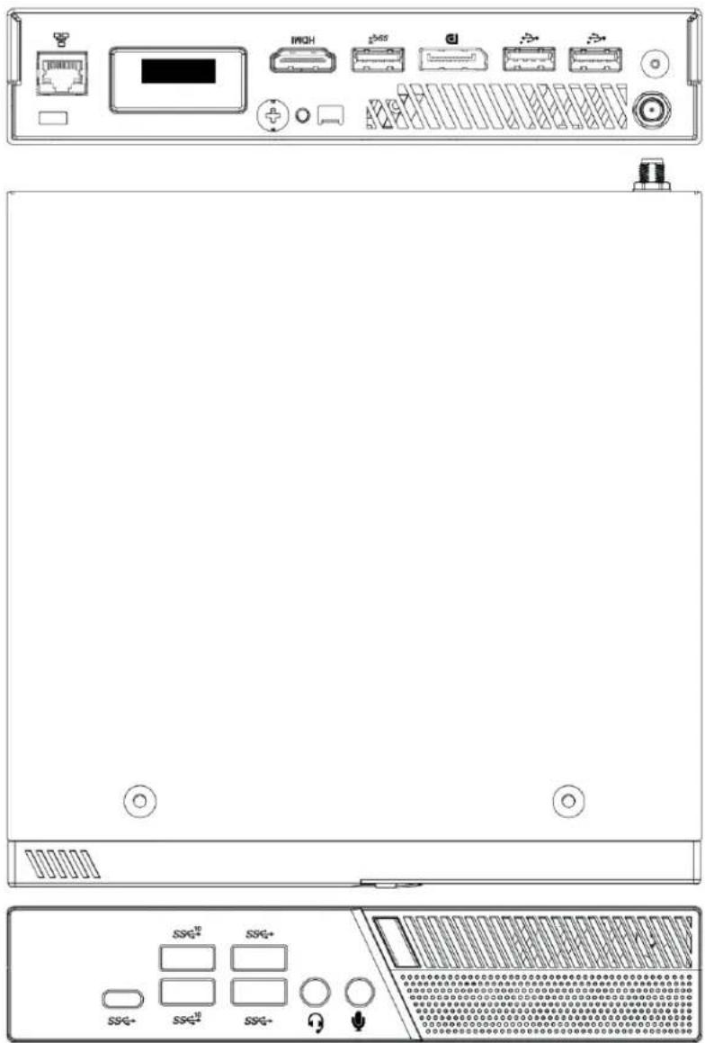
text_image
Technical diagram of a server rack with labeled ports and indicators, including front panel, rear panel, and control panel.- Lenovo UC Engine (Discontinued)

text_image
Lenovo- Once Identified, refer to the following sections for installing the devices and making system connections.
• Installing Zoom Rooms Solutions Powered by Dell UC Engine.
• Installing Zoom Rooms Solutions Powered by ASUS UC Engine.
Refer to Discontinued Solutions on page 584 to install and connect the discontinued Microsoft Teams or Zoom Rooms solutions (including solutions powered by the discontinued Lenovo UC Engine).
Installing Zoom Rooms Solutions Powered by Dell UC Engine
- Ensure you have received all the items mentioned in the In the Box section for your selected Microsoft Teams Rooms Crestron Flex solution.
- Mount all the devices applicable to your selected conferencing solution. For details, refer to Mounting Devices.
- Make connections for your selected conferencing solution. For details, refer to Connections.
In the Box
This section provides the following information:
In the Box (UC-B30-Z and UC-B30-Z-WM)
| Qty. Description | UC-B30-Z | UC-B30-Z-WM | |
| Tabletop Touch Screen | |||
| 1 10.1 | in. Tabletop Touch Screen (6510821) | √ | ✕ |
| 1 Grommet, Cable, Closed (2055455) | |||
| 1 Grommet, Cable, Open (2055456) | |||
| 1 Cover, Cable compartment (2055457) | |||
| Wall Mount Touch Screen | |||
| 1 10.1 | in. Wall Mount Touch Screen (6510814) | ✕ | √ |
| Mounting hardware | |||
| UC Bracket Assembly | |||
| 1 UC | Bracket Assembly with UC Engine and HDMI content ingest (UC-BRKT-200-S-Z-ASSY, 6512690) | √ | √ |
| 2 Anchor, Drywall, Plastic, 3/8 in. x 1/2 in. (9.5 mm x 12.7 mm) (2052565) | |||
| 1 Key, Anchor (4529654) | |||
| 2 Screw, 8-AB x 1-1/2 in. (38.1 mm), Pan Head, Combo (2052567) | |||
| 4 Tie | Wrap (2047935) | ||
| Crestron Flex Smart Soundbar with Camera | |||
| 1 UC-SB1-CAM-FLEX Soundbar with Camera (6511283) | √ | √ | |
| 1 Power supply (2045873) with cord (2042043) | |||
| 1 Cable, USB 3.0, A - B, 6 ft (1.8 m) (2053077) | |||
| Mounting hardware | |||
| Additional Items | |||
| 1 PoE | injector (6502429) | √ | √ |
| 2 Cable, CAT5e, RJ-45 - RJ-45, 7 ft (2.1 m) (6509924) | √ | √ | |
| 1 Cable, HDMI 2.1, 6 ft (1.8 m) (6512150) | √ | √ | |
| 1 Cable, HDMI, 20 ft (6.1 m) (6503567) | √ | √ | |
| 1 Cable, DisplayPortTM to HDMI, 6 ft (1.8 m) (6508282) | √ | √ | |
In the Box (UC-BX30-Z and UC-BX30-Z-WM)
| Qty. Description | UC-BX30-Z | UC-BX30-Z-WM | |
| Tabletop Touch Screen | |||
| 1 10.1 | in. Tabletop Touch Screen (6510821) | √ | ✕ |
| 1 Grommet, Cable, Closed (2055455) | |||
| 1 Grommet, Cable, Open (2055456) | |||
| 1 Cover, Cable compartment (2055457) | |||
| Wall Mount Touch Screen | |||
| 1 10.1 | in. Wall Mount Touch Screen (6510814) | ✕ | √ |
| Mounting hardware | |||
| UC Bracket Assembly | |||
| 1 UC | Bracket Assembly with UC Engine and HDMI or AV over CAT5 content ingest (UC-BRKT-260-P-Z-ASSY, 6512692) | √ | √ |
| 1 Power pack (2045870) | |||
| 2 Anchor, Drywall, Plastic, 3/8 in. x 1/2 in. (9.5 mm x 12.7 mm) (2052565) | |||
| 1 Key, Anchor (4529654) | |||
| 2 Screw, 8-AB x 1-1/2 in. (38.1 mm), Pan Head, Combo (2052567) | |||
| 4 Tie | Wrap (2047935) | ||
| Crestron Flex Smart Soundbar with Camera | |||
| 1 UC-SB1-CAM-FLEX | Soundbar with Camera (6511283) | √ | √ |
| 1 Power supply (2045873) with cord (2042043) | |||
| 1 Cable, USB 3.0, A - B, 6 ft (1.8 m) (2053077) | |||
| Mounting hardware | |||
| UC Presentation Transmitter with Cable Organizer | |||
| Qty. Description | UC-BX30-Z | UC-BX30-Z-WM |
| 1 Presentation transmitter (6510936) | ||
| 1 Cable Organizer | ||
| 1 Power pack (2056363) with cord (2001134) | ||
| 1 Bracket, power supply (2056257) | ||
| 1 Cable, USB to USB, 6.56 ft (2 m) (2056116) | ||
| 1 Cable, HDMI®, 6.56 ft (2 m) (2056117) | ||
| 1 Cable, USB 2.0, A to Micro B, 6.56 ft (2 m) (2055504) | ||
| 8 Screw, 10-9 x 5/8 in. (15.9 mm), Pan Head, Phillips, Black (2054365) | ||
| Additional Items | ||
| 1 Cable, CAT6a, RJ-45 - RJ-45, 20 ft (6.1 m) (6507640) | √ | √ |
| 3 Cable, CAT5e, RJ-45 - RJ-45, 7 ft (2.1 m) (6509924) | √ | √ |
| 1 Cable, HDMI 2.1, 6 ft (1.8 m) (6512150) | √ | √ |
| 1 Cable, DisplayPortTM to HDMI, 6 ft (1.8 m) (6508282) | √ | √ |
In the Box (UC-B31-Z and UC-B31-Z-WM)
| Qty. Description | UC-B31-Z(-INDIA) | UC-B31-Z-WM(-INDIA) | |
| Tabletop Touch Screen | |||
| 1 10.1 | in. Tabletop Touch Screen (6510821) | √ | ✕ |
| 1 Grommet, Cable, Closed (2055455) | |||
| 1 Grommet, Cable, Open (2055456) | |||
| 1 Cover, Cable compartment (2055457) | |||
| Wall Mount Touch Screen | |||
| 1 10.1 | in. Wall Mount Touch Screen (6510814) | ✕ | √ |
| Mounting hardware | |||
| UC Bracket Assembly | |||
| 1 UC | Bracket Assembly with UC Engine and HDMI content ingest (UC-BRKT-200-S-Z-ASSY, 6512690) | √ | √ |
| 2 Anchor, Drywall, Plastic, 3/8 in. x 1/2 in. (9.5 mm x 12.7 mm) (2052565) | |||
| 1 Key, Anchor (4529654) | |||
| 2 Screw, 8-AB x 1-1/2 in. (38.1 mm), Pan Head, Combo (2052567) | |||
| 4 Tie | Wrap (2047935) | ||
| Jabra® PanaCast® 50 Video Bar | |||
| 1 Jabra PanaCast 50 video bar for Crestron Flex systems (6513114) orJabra PanaCast 50 video bar for Crestron Flex systems, India (6512698) | √ | √ | |
| Additional Items | |||
| 1 PoE | injector (6502429) | √ | √ |
| 2 Cable, CAT5e, RJ-45 - RJ-45, 7 ft (2.1 m) (6509924) | √ | √ | |
| 1 Cable, HDMI 2.1, 6 ft (1.8 m) (6512150) | √ | √ | |
| 1 Cable, HDMI, 20 ft (6.1 m) (6503567) | √ | √ | |
| 1 Cable, DisplayPortTM to HDMI, 6 ft (1.8 m) (6508282) | √ | √ | |
Qty. Description
UC-BX31-Z(-INDIA) UC-BX31-Z-WM(-INDIA)
Tabletop Touch Screen
1 10.1 in. Tabletop Touch Screen (6510821)
1 Grommet, Cable, Closed (2055455)
1 Grommet, Cable, Open (2055456)
1 Cover, Cable compartment (2055457)
Wall Mount Touch Screen
1 10.1 in. Wall Mount Touch Screen (6510814) Mounting hardware
UC Bracket Assembly
1 UC Bracket Assembly with UC Engine and HDMI or AV over CAT5 content ingest (UC-BRKT-260-P-Z-ASSY, 6512692)
1 Power pack (2045870)
2 Anchor, Drywall, Plastic, 3/8 in. x 1/2 in. (9.5 mm x 12.7 mm) (2052565)
1 Key, Anchor (4529654)
2 Screw, 8-AB x 1-1/2 in. (38.1 mm), Pan Head, Combo (2052567)
4 Tie Wrap (2047935)
Jabra® PanaCast® 50 Video Bar
1 Jabra PanaCast 50 video bar for Crestron Flex systems (6513114) or Jabra PanaCast 50 video bar for Crestron Flex systems, India (6512698)
UC Presentation Transmitter with Cable Organizer
| Qty. Description | UC-BX31-Z(-INDIA) | UC-BX31-Z-WM(-INDIA) |
| 1 Presentation transmitter (6510936) | ||
| 1 Cable Organizer | ||
| 1 Power pack (2056363) with cord (2001134) | ||
| 1 Bracket, power supply (2056257) | ||
| 1 Cable, USB to USB, 6.56 ft (2 m) (2056116) | ||
| 1 Cable, HDMI®, 6.56 ft (2 m) (2056117) | ||
| 1 Cable, USB 2.0, A to Micro B, 6.56 ft (2 m) (2055504) | ||
| 8 Screw, 10-9 x 5/8 in. (15.9 mm), Pan Head, Phillips, Black (2054365) | ||
| Additional Items | ||
| 1 Cable, CAT6a, RJ-45 - RJ-45, 20 ft (6.1 m) (6507640) | √ | √ |
| 3 Cable, CAT5e, RJ-45 - RJ-45, 7 ft (2.1 m) (6509924) | √ | √ |
| 1 Cable, HDMI 2.1, 6 ft (1.8 m) (6512150) | √ | √ |
| 1 Cable, DisplayPortTM to HDMI, 6 ft (1.8 m) (6508282) | √ | √ |
In the Box (UC-C100-Z and UC-C100-Z-WM)
| Qty. Description | UC-C100-Z | UC-C100-Z-WM | |
| Tabletop Touch Screen | |||
| 1 10.1 | in. Tabletop Touch Screen (6510821) | √ | ✕ |
| 1 Grommet, Cable, Closed (2055455) | |||
| 1 Grommet, Cable, Open (2055456) | |||
| 1 Cover, Cable compartment (2055457) | |||
| Wall Mount Touch Screen | |||
| 1 10.1 | in. Wall Mount Touch Screen (6510814) | ✕ | √ |
| Mounting hardware | |||
| UC Bracket Assembly | |||
| 1 UC | Bracket Assembly with UC Engine and HDMI content ingest (UC-BRKT-200-S-Z-ASSY, 6512690) | √ | √ |
| 2 Anchor, Drywall, Plastic, 3/8 in. x 1/2 in. (9.5 mm x 12.7 mm) (2052565) | |||
| 1 Key, Anchor (4529654) | |||
| 2 Screw, 8-AB x 1-1/2 in. (38.1 mm), Pan Head, Combo (2052567) | |||
| 4 Tie | Wrap (2047935) | ||
| Additional Items | |||
| 1 PoE | injector (6502429) | √ | √ |
| 2 Cable, CAT5e, RJ-45 - RJ-45, 7 ft (2.1 m) (6509924) | √ | √ | |
| 1 Cable, HDMI 2.1, 6 ft (1.8 m) (6512150) | √ | √ | |
| 1 Cable, HDMI, 20 ft (6.1 m) (6503567) | √ | √ | |
| 1 Cable, DisplayPortTM to HDMI, 6 ft (1.8 m) (6508282) | √ | √ | |
In the Box (UC-CX100-Z and UC-CX100-Z-WM)
| Qty. Description | UC-CX100-Z | UC-CX100-Z-WM | |
| Tabletop Touch Screen | |||
| 1 10.1 | in. Tabletop Touch Screen (6510821) | √ | ✕ |
| 1 Grommet, Cable, Closed (2055455) | |||
| 1 Grommet, Cable, Open (2055456) | |||
| 1 Cover, Cable compartment (2055457) | |||
| Wall Mount Touch Screen | |||
| 1 10.1 | in. Wall Mount Touch Screen (6510814) | ✕ | √ |
| Mounting hardware | |||
| UC Bracket Assembly | |||
| 1 UC | Bracket Assembly with UC Engine and HDMI or AV over CAT5 content ingest (UC-BRKT-260-P-Z-ASSY, 6512692) | √ | √ |
| 1 Power pack (2045870) | |||
| 2 Anchor, Drywall, Plastic, 3/8 in. x 1/2 in. (9.5 mm x 12.7 mm) (2052565) | |||
| 1 Key, Anchor (4529654) | |||
| 2 Screw, 8-AB x 1-1/2 in. (38.1 mm), Pan Head, Combo (2052567) | |||
| 4 Tie | Wrap (2047935) | ||
| UC Presentation Transmitter with Cable Organizer | |||
| 1 Presentation transmitter (6510936) | √ | √ | |
| 1 Cable Organizer | |||
| 1 Power pack (2056363) with cord (2001134) | |||
| 1 Bracket, power supply (2056257) | |||
| 1 Cable, USB to USB, 6.56 ft (2 m) (2056116) | |||
| 1 Cable, HDMI®, 6.56 ft (2 m) (2056117) | |||
| 1 Cable, USB 2.0, A to Micro B, 6.56 ft (2 m) (2055504) | |||
| 8 Screw, 10-9 x 5/8 in. (15.9 mm), Pan Head, Phillips, Black (2054365) | |||
| Additional Items | |||
| 1 Cable, CAT6a, RJ-45 - RJ-45, 20 ft (6.1 m) (6507640) | ✕ | ✕ | |
| 3 Cable, CAT5e, RJ-45 - RJ-45, 7 ft (2.1 m) (6509924) | √ | √ | |
| 1 Cable, HDMI 2.1, 6 ft (1.8 m) (6512150) | √ | √ | |
| 1 Cable, DisplayPortTM to HDMI, 6 ft (1.8 m) (6508282) | √ | √ | |
In the Box (UC-MM30-Z and UC-MM30-Z-I)
| Qty. Description | |
| UC Bracket Assembly | |
| 1 UC | Bracket Assembly with UC Engine and HDMI content ingest (UC-BRKT-200-S-Z-ASSY, 6512690) |
| 2 Anchor, Drywall, Plastic, 3/8 in. x 1/2 in. (9.5 mm x 12.7 mm) (2052565) | |
| 1 Key, Anchor (4529654) | |
| 2 Screw, 8-AB x 1-1/2 in. (38.1 mm), Pan Head, Combo (2052567) | |
| 4 Tie | Wrap (2047935) |
| Mini Tabletop Conference Device | |
| 1 Flex | MM Tabletop Conference Device, Microsoft Teams video (6511615 or 6511616) |
| 1 PoE+ | Injector (2055605) |
| 2 Cable, CAT5e, RJ-45 - RJ-45, 11.8 ft (3.6 m) (2056204) | |
| 1 Cable, USB 2.0, A - Micro B, 5.8 ft (1.8 m) (2055579) | |
| Camera | |
| 1 Collaboration camera (6510482) | |
| 1 Camera wall mount kit (6510998) | |
| Additional Items | |
| 1 Cable, CAT5e, RJ-45 - RJ-45, 7 ft (2.1 m) (6509924) | |
| 1 Cable, HDMI 2.1, 6 ft (1.8 m) (6512150) | |
| 1 Cable, HDMI, 20 ft (6.1 m) (6503567) | |
| 1 Cable, DisplayPortTM to HDMI, 6 ft (1.8 m) (6508282) | |
| 1 Cable, USB Extension, USB Type A Male-to-Female, 15 ft (4.6 m) (6508260) | |
| 1 Cable, USB 3.0, Right angle USB-C to A, 6 ft (1.8 m) (6511591) | |
In the Box (UC-MMX30-Z and UC-MMX30-Z-I)
| Qty. Description | |
| UC Bracket Assembly | |
| 1 UC | Bracket Assembly with UC Engine and HDMI or AV over CAT5 content ingest (UC-BRKT-260-P-Z-ASSY, 6512692) |
| 1 Power pack (2045870) | |
| 2 Anchor, Drywall, Plastic, 3/8 in. x 1/2 in. (9.5 mm x 12.7 mm) (2052565) | |
| 1 Key, Anchor (4529654) | |
| 2 Screw, 8-AB x 1-1/2 in. (38.1 mm), Pan Head, Combo (2052567) | |
| 4 Tie Wrap (2047935) | |
| UC Presentation Transmitter with Cable Organizer | |
| 1 Presentation transmitter (6510936) | |
| 1 Cable Organizer | |
| 1 Power pack (2056363) with cord (2001134) | |
| 1 Bracket, power supply (2056257) | |
| 1 Cable, USB to USB, 6.56 ft (2 m) (2056116) | |
| 1 Cable, HDMI®, 6.56 ft (2 m) (2056117) | |
| 1 Cable, USB 2.0, A to Micro B, 6.56 ft (2 m) (2055504) | |
| 8 Screw, 10-9 x 5/8 in. (15.9 mm), Pan Head, Phillips, Black (2054365) | |
| Mini Tabletop Conference Device | |
| 1 Flex MM Tabletop Conference Device, Microsoft Teams video (6511615 or 6511616) | |
| 1 PoE+ Injector (2055605) | |
| 2 Cable, CAT5e, RJ-45 - RJ-45, 11.8 ft (3.6 m) (2056204) | |
| 1 Cable, USB 2.0, A - Micro B, 5.8 ft (1.8 m) (2055579) | |
| Camera | |
| 1 Collaboration camera (6510482) | |
| 1 Camera wall mount kit (6510998) | |
| Additional Items | |
| 2 Cable, CAT6a, RJ-45 - RJ-45, 20 ft (6.1 m) (6507640) | |
| 1 Cable, CAT5e, RJ-45 - RJ-45, 7 ft (2.1 m) (6509924) | |
Qty. Description
| 1 Cable, HDMI 2.1, 6 ft (1.8 m) (6512150) |
| 1 Cable, DisplayPortTM to HDMI, 6 ft (1.8 m) (6508282) |
| 1 Cable, USB 3.0, Right angle USB-C to A, 6 ft (1.8 m) (6511591) |
In the Box (UC-M50-Z)
| Qty. Description | |
| UC Bracket Assembly | |
| 1 UC | Bracket Assembly with UC Engine and HDMI content ingest (UC-BRKT-200-S-Z-ASSY, 6512690) |
| 2 Anchor, Drywall, Plastic, 3/8 in. x 1/2 in. (9.5 mm x 12.7 mm) (2052565) | |
| 1 Key, Anchor (4529654) | |
| 2 Screw, 8-AB x 1-1/2 in. (38.1 mm), Pan Head, Combo (2052567) | |
| 4 Tie | Wrap (2047935) |
| Mercury Tabletop Conference Device | |
| 1 Tabletop Conference Device, Microsoft Teams video (6508227) | |
| 1 Cable, CAT5e, RJ-45 - RJ-45, 12 ft (3.7 m) (2033988) | |
| 1 Cable Retention Plate (2047908) | |
| 3 Tie | Wrap (2047935) |
| Camera | |
| 1 Collaboration camera (6510482) | |
| 1 Camera wall mount kit (6510998) | |
| Additional Items | |
| 1 Cable, CAT5e, RJ-45 - RJ-45, 7 ft (2.1 m) (6509924) | |
| 1 Cable, HDMI 2.1, 6 ft (1.8 m) (6512150) | |
| 1 Cable, HDMI, 20 ft (6.1 m) (6503567) | |
| 1 Cable, DisplayPortTM to HDMI, 6 ft (1.8 m) (6508282) | |
| 1 Cable, USB Extension, USB Type A Male-to-Female, 15 ft (4.6 m) (6508260) | |
| 1 Cable, USB 3.0, Right angle USB-C to A, 6 ft (1.8 m) (6511591) | |
| 1 Cable, USB 2.0, A - Micro-B, 6 ft (1.8 m) (6510947) | |
| 1 Power supply (6500187) | |
In the Box (UC-MX50-Z)
| Qty. Description | |
| UC Bracket Assembly | |
| 1 UC | Bracket Assembly with UC Engine and HDMI or AV over CAT5 content ingest (UC-BRKT-260-P-Z-ASSY, 6512692) |
| 1 Power pack (2045870) | |
| 2 Anchor, Drywall, Plastic, 3/8 in. x 1/2 in. (9.5 mm x 12.7 mm) (2052565) | |
| 1 Key, Anchor (4529654) | |
| 2 Screw, 8-AB x 1-1/2 in. (38.1 mm), Pan Head, Combo (2052567) | |
| 4 Tie Wrap (2047935) | |
| Mercury X Tabletop Conference Device | |
| 1 Tabletop Conference Device, Microsoft Teams video (6510610) | |
| 1 Cable, CAT5e, RJ-45 - RJ-45, 12 ft (3.7 m) (2033988) | |
| 1 Cable Retention Plate (2047908) | |
| 1 Power supply (2045873) with cord (2042043) | |
| 3 Tie Wrap (2047935) | |
| Camera | |
| 1 Collaboration camera (6510482) | |
| 1 Camera wall mount kit (6510998) | |
| Additional Items | |
| 2 Cable, CAT6a, RJ-45 - RJ-45, 20 ft (6.1 m) (6507640) | |
| 1 Cable, CAT5e, RJ-45 - RJ-45, 7 ft (2.1 m) (6509924) | |
| 1 Cable, HDMI 2.1, 6 ft (1.8 m) (6512150) | |
| 1 Cable, DisplayPortTM to HDMI, 6 ft (1.8 m) (6508282) | |
| 1 Cable, USB 3.0, Right angle USB-C to A, 6 ft (1.8 m) (6511591) | |
| 1 Cable, USB 2.0, A - Micro-B, 6 ft (1.8 m) (6510947) | |
| 1 Cable, thin HDMI, 6 ft (1.8 m) (6510946) | |
In the Box (UC-M50-Z-UPGRD)
| Qty. Description | |
| UC Bracket Assembly | |
| 1 UC | Bracket Assembly with UC Engine and HDMI content ingest (UC-BRKT-200-S-Z-ASSY, 6512690) |
| 2 Anchor, Drywall, Plastic, 3/8 in. x 1/2 in. (9.5 mm x 12.7 mm) (2052565) | |
| 1 Key, Anchor (4529654) | |
| 2 Screw, 8-AB x 1-1/2 in. (38.1 mm), Pan Head, Combo (2052567) | |
| 4 Tie | Wrap (2047935) |
| Additional Items | |
| 1 Cable, CAT5e, RJ-45 - RJ-45, 7 ft (2.1 m) (6509924) | |
| 1 Cable, HDMI 2.1, 6 ft (1.8 m) (6512150) | |
| 1 Cable, HDMI, 20 ft (6.1 m) (6503567) | |
| 1 Cable, DisplayPortTM to HDMI, 6 ft (1.8 m) (6508282) | |
| 1 Cable, USB Extension, USB Type A Male-to-Female, 15 ft (4.6 m) (6508260) | |
In the Box (UC-MX50-Z-UPGRD)
| Qty. Description | |
| UC Bracket Assembly | |
| 1 UC | Bracket Assembly with UC Engine and HDMI or AV over CAT5 content ingest (UC-BRKT-260-P-Z-ASSY, 6512692) |
| 1 Power pack (2045870) | |
| 2 Anchor, Drywall, Plastic, 3/8 in. x 1/2 in. (9.5 mm x 12.7 mm) (2052565) | |
| 1 Key, Anchor (4529654) | |
| 2 Screw, 8-AB x 1-1/2 in. (38.1 mm), Pan Head, Combo (2052567) | |
| 4 Tie | Wrap (2047935) |
| Additional Items | |
| 1 Cable, CAT5e, RJ-45 - RJ-45, 7 ft (2.1 m) (6509924) | |
| 1 Cable, DisplayPortTM to HDMI, 6 ft (1.8 m) (6508282) | |
In the Box (UC-M70-Z)
| Qty. Description | |
| UC Bracket Assembly | |
| 1 UC | Bracket Assembly with UC Engine and HDMI content ingest (UC-BRKT-200-S-Z-ASSY, 6512690) |
| 2 Anchor, Drywall, Plastic, 3/8 in. x 1/2 in. (9.5 mm x 12.7 mm) (2052565) | |
| 1 Key, Anchor (4529654) | |
| 2 Screw, 8-AB x 1-1/2 in. (38.1 mm), Pan Head, Combo (2052567) | |
| 4 Tie | Wrap (2047935) |
| Mercury Tabletop Conference Device | |
| 1 Tabletop Conference Device, Microsoft Teams video (6508227) | |
| 1 Cable, CAT5e, RJ-45 - RJ-45, 12 ft (3.7 m) (2033988) | |
| 1 Cable Retention Plate (2047908) | |
| 3 Tie | Wrap (2047935) |
| CCS-CAM-L1 AI Collaboration Camera | |
| 1 AI collaboration camera (6512296) | |
| Microphone Pod | |
| 1 Extension Microphone Pod (6508084) | |
| Additional Items | |
| 1 Cable, CAT5e, RJ-45 - RJ-45, 7 ft (2.1 m) (6509924) | |
| 1 Cable, HDMI 2.1, 6 ft (1.8 m) (6512150) | |
| 1 Cable, HDMI, 20 ft (6.1 m) (6503567) | |
| 1 Cable, DisplayPortTM to HDMI, 6 ft (1.8 m) (6508282) | |
| 1 Cable, USB Extension, USB Type A Male-to-Female, 15 ft (4.6 m) (6508260) | |
| 1 Cable, USB 2.0, A - Micro-B, 6 ft (1.8 m) (6510947) | |
| 1 Power supply (6500187) | |
In the Box (UC-MX70-Z)
| Qty. Description | |
| UC Bracket Assembly | |
| 1 UC | Bracket Assembly with UC Engine and HDMI or AV over CAT5 content ingest (UC-BRKT-260-P-Z-ASSY, 6512692) |
| 1 Power pack (2045870) | |
| 2 Anchor, Drywall, Plastic, 3/8 in. x 1/2 in. (9.5 mm x 12.7 mm) (2052565) | |
| 1 Key, Anchor (4529654) | |
| 2 Screw, 8-AB x 1-1/2 in. (38.1 mm), Pan Head, Combo (2052567) | |
| 4 Tie Wrap (2047935) | |
| Mercury X Tabletop Conference Device | |
| 1 Tabletop Conference Device, Microsoft Teams video (6510610) | |
| 1 Cable, CAT5e, RJ-45 - RJ-45, 12 ft (3.7 m) (2033988) | |
| 1 Cable Retention Plate (2047908) | |
| 1 Power supply (2045873) with cord (2042043) | |
| 3 Tie Wrap (2047935) | |
| CCS-CAM-L1 AI Collaboration Camera | |
| 1 AI collaboration camera (6512296) | |
| Microphone Pod | |
| 1 Extension Microphone Pod (6508084) | |
| Additional Items | |
| 2 Cable, CAT6a, RJ-45 - RJ-45, 20 ft (6.1 m) (6507640) | |
| 1 Cable, CAT5e, RJ-45 - RJ-45, 7 ft (2.1 m) (6509924) | |
| 1 Cable, HDMI 2.1, 6 ft (1.8 m) (6512150) | |
| 1 Cable, DisplayPortTM to HDMI, 6 ft (1.8 m) (6508282) | |
| 1 Cable, USB 2.0, A - Micro-B, 6 ft (1.8 m) (6510947) | |
| 1 Cable, thin HDMI, 6 ft (1.8 m) (6510946) | |
In the Box (UC-M70-NC-Z)
| Qty. Description | |
| UC Bracket Assembly | |
| 1 UC | Bracket Assembly with UC Engine and HDMI content ingest (UC-BRKT-200-S-Z-ASSY, 6512690) |
| 2 Anchor, Drywall, Plastic, 3/8 in. x 1/2 in. (9.5 mm x 12.7 mm) (2052565) | |
| 1 Key, Anchor (4529654) | |
| 2 Screw, 8-AB x 1-1/2 in. (38.1 mm), Pan Head, Combo (2052567) | |
| 4 Tie | Wrap (2047935) |
| Mercury Tabletop Conference Device | |
| 1 Tabletop Conference Device, Microsoft Teams video (6508227) | |
| 1 Cable, CAT5e, RJ-45 - RJ-45, 12 ft (3.7 m) (2033988) | |
| 1 Cable Retention Plate (2047908) | |
| 3 Tie | Wrap (2047935) |
| Microphone Pod | |
| 1 Extension Microphone Pod (6508084) | |
| Additional Items | |
| 1 Cable, CAT5e, RJ-45 - RJ-45, 7 ft (2.1 m) (6509924) | |
| 1 Cable, HDMI 2.1, 6 ft (1.8 m) (6512150) | |
| 1 Cable, HDMI, 20 ft (6.1 m) (6503567) | |
| 1 Cable, DisplayPortTM to HDMI, 6 ft (1.8 m) (6508282) | |
| 1 Cable, USB Extension, USB Type A Male-to-Female, 15 ft (4.6 m) (6508260) | |
| 1 Cable, USB 2.0, A - Micro-B, 6 ft (1.8 m) (6510947) | |
| 1 Power supply (6500187) | |
In the Box (UC-MX70-NC-Z)
| Qty. Description | |
| UC Bracket Assembly | |
| 1 UC Bracket Assembly with UC Engine and HDMI or AV over CAT5 content ingest (UC-BRKT-260-P-Z-ASSY, 6512692) | |
| 1 Power pack (2045870) | |
| 2 Anchor, Drywall, Plastic, 3/8 in. x 1/2 in. (9.5 mm x 12.7 mm) (2052565) | |
| 1 Key, Anchor (4529654) | |
| 2 Screw, 8-AB x 1-1/2 in. (38.1 mm), Pan Head, Combo (2052567) | |
| 4 Tie Wrap (2047935) | |
| Mercury X Tabletop Conference Device | |
| 1 Tabletop Conference Device, Microsoft Teams video (6510610) | |
| 1 Cable, CAT5e, RJ-45 - RJ-45, 12 ft (3.7 m) (2033988) | |
| 1 Cable Retention Plate (2047908) | |
| 1 Power supply (2045873) with cord (2042043) | |
| 3 Tie Wrap (2047935) | |
| Microphone Pod | |
| 1 Extension Microphone Pod (6508084) | |
| Additional Items | |
| 2 Cable, CAT6a, RJ-45 - RJ-45, 20 ft (6.1 m) (6507640) | |
| 1 Cable, CAT5e, RJ-45 - RJ-45, 7 ft (2.1 m) (6509924) | |
| 1 Cable, HDMI 2.1, 6 ft (1.8 m) (6512150) | |
| 1 Cable, DisplayPortTM to HDMI, 6 ft (1.8 m) (6508282) | |
| 1 Cable, USB 2.0, A - Micro-B, 6 ft (1.8 m) (6510947) | |
| 1 Cable, thin HDMI, 6 ft (1.8 m) (6510946) | |
Mounting Devices
Mount the applicable devices based on your selected Crestron Flex solution.
Mounting CCS-UC-1 Tabletop Conference Device
The CCS-UC-1 Tabletop Conference Device can be placed on any flat surface or secured on a table using the CCS-UCA-SMK tabletop swivel mount kit (sold separately).
Mounting UC-2 Mini Tabletop Conference Device
The UC-2 Mini Tabletop Conference Device can be placed on any flat surface or secured on a table using the UCA-SMK-UC2 or UCA-SMKR-UC2-3 tabletop swivel mount kit (sold separately).
Buttons and Indicators
Tap one of the four mute buttons located at each corner of the device to mute or unmute the integrat microphone.
A light bar is located above the screen. LEDs are located behind the mute buttons and light bar and will respond to muting or unmuting the microphone.

text_image
Light bar Mute button (x2) Mute button (x2)The four mute buttons and the light bar will display red or green to indicate the following states:
• Lighted green: The microphone is unmuted.
• Lighted red: The microphone is muted.
- Flashing green: The device is powering on.
Factory Reset the Device
A factory reset may be performed when troubleshooting the conference device.
To perform a factory reset on the conference device:
- Power cycle the device by disconnecting and reconnecting the CAT5e cable from the conference device.
- When the device powers on and the LEDs flash green, tap the button below the Crestron® logo 10 times. A factory reset confirmation screen appears.
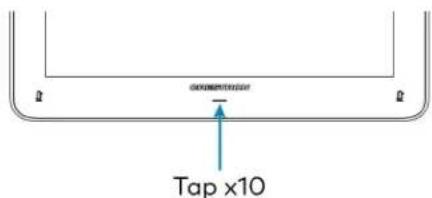
text_image
Tap x10- Tap one of the mute buttons to move the selector on the factory reset confirmation screen to Yes. Tap the button below the Crestron logo to confirm the factory reset.

text_image
Tap to move selector Tap to move selector Tap to confirm- The device will reboot. Configure the device according to the Crestron Flex system's Quick Start Guide.
Declaration
NCC警语
NCC Regulatory Information
Support Frequency Bands and Power:
BT< 8 dBm;
WLAN 2412-2462 MHz < 25 dBm;
WLAN 5150-5825 MHz < 18 dBm;
Mounting TS-1070-B-S Tabletop Touch Screen
The TS-1070-B-S Tabletop Touch Screen can be placed on the conference table or any flat surface.
Mounting TSW-1070-B-S Wall Mount Touch Screen
Mount the included touch screen according to the TSW-70 Series Product Manual (Doc. 8550).
Mounting the UC Bracket Assembly
Mount the UC Bracket Assembly to VESA® compliant display devices, a wall, or other building structure. Anchors and screws are supplied for installation on walls with 3/8 in. (9.5 mm) to 3/4 in. (19 mm) thickness.
CAUTION: Preinstalled screws may protrude from the back of the UC Bracket Assembly. Exercise caution when handling the UC Bracket Assembly to avoid scratching or damaging surfaces.
NOTE: The integrated cable tie wraps are reusable. Avoid damaging the cable tie wraps.
Mounting UC-CAM-L1
Mount the camera according to its included documentation.
Mounting CCS-CAM-USB-F-400
Mount the camera using the included UC-CAM-WMK wall mount kit.
The wall mount kit provides secure mounting options for CCS-CAM-USB-F-400. It comes with two mounting brackets and mounting hardware that allow for a variety of mounting locations.
In the Box (UC-CAM-WMK)
| Qty. Description | |
| 1 UC-CAM-WMK, Wall Mount Kit for CCS-CAM-USB-F-400 (6510998) | |
| Additional Items | |
| 2 Anchor, Wall, Plastic, #6 x 1-1/4 in. (2043585) | |
| 1 Bracket, Camera, 2.00 in. to 3.50 in. (51 mm to 89 mm) (2053562) | |
| 1 Bracket, Camera, 3.50 in. to 5.00 in. (89 mm to 127 mm) (2053561) | |
| 1 Screw, 1/4-20, 5/16 in., Flat Head, Phillips (2040253) | |
| 2 Screw, 6-AB x 1 in., Pan Head, Phillips, Black (2053606) | |
| 2 Tie Wrap, Releasable (2005430) | |
Installing the Wall Mount Kit
Select an appropriate mounting location and install the bracket.
Choose a Location
For optimal viewing results, the bracket should be mounted in a location that places the camera above the plane of the room's conference table.
Choose a Bracket
The wall mount kit comes with two brackets to accommodate a variety of mounting locations. The smaller bracket allows the back of the camera to be placed 2.00 in. to 3.50 in. (51 mm to 89 mm) off wall while the larger bracket allows the back of the camera to be placed 3.50 in. to 5.00 in. (89 mm to 127 mm) off the wall.
NOTES:
- The camera can be mounted on top of or under the bracket.
- When using the CCS-CAM-USB-F-100, the smaller bracket allows the back of the camera to be placed 2.25 in. to 3.00 in. (57 mm to 76 mm) off the wall while the larger bracket allows the back of the camera to be placed 3.75 in. to 4.55 in. (95 mm to 116 mm) off the wall.
Small bracket, CCS-CAM-USB-F-400 camera shown

text_image
Camera 3.50 in. (89 mm) 2.00 in. (51 mm) Screw, 6-AB x 1 in., Pan Head (x2) Bracket 3.80 in. (97 mm) 1.50 in. (38 mm) 4.61 in. (117 mm) 6.35 in. (162 mm) USB PortLarge bracket, CCS-CAM-USB-F-400 camera shown

text_image
5.00 in. (127 mm) 3.50 in. (89 mm) Camera Bracket Screw, 6-AB x 1 in., Pan Head (x2) 1.50 in. (38 mm) 3.80 in. (97 mm) 1.30 in. (33 mm) 6.10 in. (155 mm) USB Port 7.85 in. (199 mm)Secure the Bracket
Secure the bracket to the mounting surface with the included 6-AB x 1 in. pan head screws. Use the included anchors for mounting locations where a stud cannot be found.
Secure the bracket (large bracket shown)

text_image
Screw, 6-AB x 1 in., Pan Head (x2) BracketAttach the Camera
Attach the camera to the bracket with the included 1/4-20, 5/16 in. flat head screw. The camera can be positioned forward and back along the bracket.
Attach the camera (large bracket with CCS-CAM-USB-F-400 camera shown)

text_image
RUB BLT Camera Notch Bracket Screw, 1/4-20, 5/16 in., Flat HeadConnect
Thread the cable that is included with the camera through the notch in the bracket and connect it to the camera's USB port and a USB device. Use the included tie wraps to secure excess cable.
NOTE: On the CCS-CAM-USB-F-100, the cable is attached to the camera.
Mounting UC-SB1-CAM-FLEX
In the Box
Qty. Description
| 1 UC-SB1-CAM-FLEX, UC Video Conference Smart Soundbar & Camera (6511283) |
| Additional Items |
| 4 Anchor, Drywall, Plastic, 3/8 in. x 1/2 in. (2052565) |
| 1 Cable, USB 3.0, A - B, 6 ft (1.83 m) (2053077) |
| 2 Foot, 2.3 in. x 0.96 in. x 0.15 in., Rubber (2052169) |
| 1 Key, Anchor (4529654) |
| 1 Power Cord, 5 ft 10 in. (1.78 m) (2042043) |
| 1 Power Pack, 24 VDC, 2.5 A, 100-240 VAC (2045873) |
| 4 Screw, 8-AB x 1-1/2 in., Pan Head, Combo (2052567) |
| 1 Template, Overlay (4529513) |
The soundbar can be placed on a flat surface or mounted on a wall. The soundbar has the following dimensions.
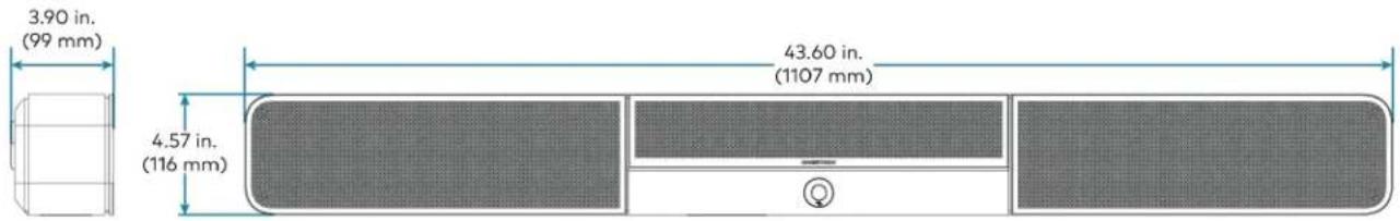
text_image
3.90 in. (99 mm) 43.60 in. (1107 mm) 4.57 in. (116 mm)Place on a Flat Surface
If the soundbar is to be placed on a flat surface, attach the included rubber feet to the bottom of the soundbar as shown.

text_image
Attach feet hereMount on a Wall
The soundbar includes anchors that are suitable for mounting it on sheetrock walls up to 1/2 in. (13 mm thickness. Masonry and other materials may require additional installer-supplied mounting hardware.
NOTES:
- For optimal viewing results, the soundbar should be mounted in a location that places the camera approximately 12 in. (305 mm) above the plane of the room's conference table.
- When mounting on a wall beneath a display device, leave 3/4 in. (19 mm) (minimum) clearance above the top of the soundbar. Use the included template to allow for sufficient clearance between the soundbar and display device.
The following tools are required to mount the soundbar:
• Drywall saw (not included)
- Drill with 5/16 in. bit (not included)
A template is included to provide drill hole locations for the included mounting hardware.
- Attach the template to the desired mounting location with the template's center reference line at the center of the desired location.
NOTE: Use the center reference hole of the template as a guide to attach the template.

text_image
Drill one of these two holes Cutout for soundbar cables Center reference hole Drill one of these two holes SOUNDBAR ACTUAL HEIGHT MIN. DISTANCE FROM BOTTOM OF DISPLAY CENTER REFERENCE HOLE TO HOLD TEMPLATE TEMPORALLY TEMPLATE - 40161 FOR UC-SB1 TOTAL OF 4 SCREWS MUST BE USED (2 ON EACH SIDE, 1 PER ROW) TO SECURE THE SOUNDBAR TO THE WALL Drill one of these two holes Center reference line Drill one of these two holes- Drill two pilot holes on each side of the center reference line as shown in the previous diagram. Each side should have one pilot hole drilled in each row of the template.
- Use a drywall saw to make a cutout in the wall for the soundbar cables. The cutout in the center of the template provides adequate access for all of the required cabling.
-
Install the four included anchors and screws into the drilled pilot holes.
-
Place the soundbar face down, and pivot the wall bracket away from the soundbar.
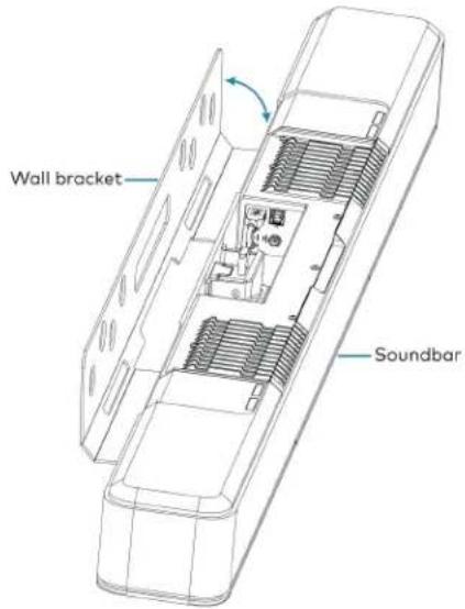
text_image
Wall bracket Soundbar- Place the wall bracket over the screws, and hand tighten the screws until the wall bracket is secured to the wall.

text_image
8-AB x 1-1/2 in. screws (x4) Wall bracket Soundbar- Route the cables through the cable cutout.
NOTE: The included power pack's cord is typically routed from the wall opening, through the cable cutout, to the soundbar.
Connect
Make the necessary connections as called out in the following diagram. Connect power last. Once all connections are made, pivot the soundbar up to the wall bracket until the soundbar locks into place.
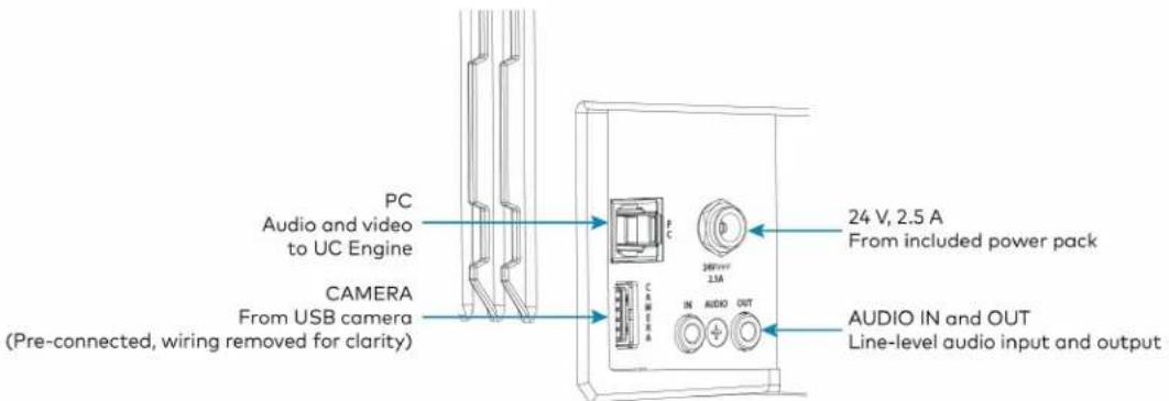
text_image
PC Audio and video to UC Engine CAMERA From USB camera (Pre-connected, wiring removed for clarity) 24 V, 2.5 A From included power pack AUDIO IN and OUT Line-level audio input and output- PC: Connect the included USB cable to the PC port and to a USB port on the UC Engine. For optimal results, use a USB 3.0 connection.
• CAMERA: The integrated camera is already connected from the factory.
• 24 V, 2.5 A: Connect the power pack to the 24 V, 2.5 A power input and to an AC power out
- AUDIO IN and AUDIO OUT: The soundbar provides unbalanced, stereo, analog input and output jacks (3.5 mm TRS mini-phone). The AUDIO IN port accommodates an optional line-level audio source which feeds to the internal amplifier and speakers without a volume control or other signal processing. The AUDIO OUT port provides a line-level signal for an optional assistive listening system and carries the same audio signal as the soundbar speakers.
Status and System Control
When used as part of a Crestron Flex system, the soundbar is controlled by the system's touch screen.
The front panel status bar illuminates to provide operational information.
- A green status bar indicates the volume level. Raising the volume increases the status bar's illumination. Lowering the volume decreases the status bar's illumination. When the volume = "0", the status bar is unlit.

natural_image
Front view of a white electronic device with a green horizontal bar and circular button (no visible text or symbols)- Muting the microphone and speaker turns the two outer segments of the status bar red.

natural_image
Top-down view of a sound chamber with sound waves, central speaker grille, and circular button (no text or symbols)- Muting the microphone turns the center of the status bar red.

natural_image
Front view of a modern air conditioner unit with ventilation grilles and a red horizontal stripe (no text or symbols visible)Mounting UC-SB-P50(-INDIA)
Mount the Jabra PanaCast 50 intelligent video bar for Crestron Flex Systems according to its included documentation.
Mounting the UC-PR and Cable Organizer
Mount the UC Presentation Transmitter to the underside of a table using the supplied screws. The supplied screws support installation on tables with a thickness of 1 in. (25.4 mm) minimum.
The included Crestron cable organizer for the UC-PR provides convenient tabletop cable management. The cable organizer routes audio and network connections from the UC-PR to a system's tabletop controller and routes audio and video connections to a user's laptop for Bring Your Own Device (BYOD) presentation.
In the Box (Cable Organizer)
| Qty. Description | |
| 1 Cable Organizer | |
| Additional Items | |
| 1 Cable organizer housing, Plastic, Black (2056826) | |
| 1 Cable organizer plate, Plastic, Black (2056825) | |
| 2 Locking nut, Plastic, Black (2056824) | |
| 2 Screw, 04-40, 3/8 in., Pan Head, Phillips, Black (2007170) | |
| 5 Cable tie wrap, 7.4 in. x 0.19 in., Black (2057355) | |
Installing the Cable Organizer
To install the cable organizer:
- Select a mounting surface with a thickness of 1 in. (25 mm) to 1.5 in. (38 mm).
- Use a hole saw to cut a 2.5 in. (64 mm) wide mounting hole in the mounting surface.
- Insert the cable organizer housing into the mounting hole.

text_image
Cable organizer housing 2.5 in. (64 mm) wide mounting hole Surface thickness: 1 in. - 1.5 in. (25 mm - 38 mm)- Secure the cable organizer housing to the mounting surface using the included locking nuts. Ensure that the TOP label on the locking nuts faces the mounting surface.
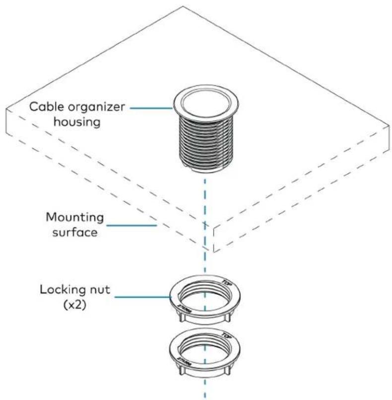
text_image
Cable organizer housing Mounting surface Locking nut (x2)-
Pass cables through the bottom of the cable organizer housing to the tabletop.
-
Route the cables through the routing holes on the cable organizer plate. All of the necessary cables are included with the Crestron Flex conference system.
NOTE: The USB B routing hole is only used in systems with a Crestron Flex MM tabletop conference device.
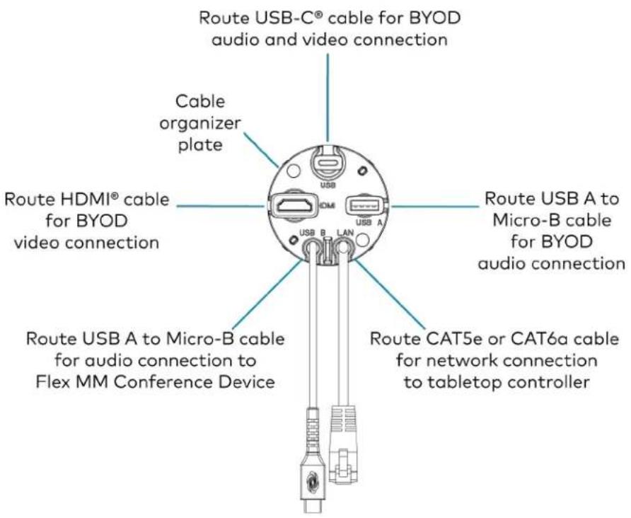
text_image
Route USB-C® cable for BYOD audio and video connection Cable organizer plate Route HDMI® cable for BYOD video connection USB A to Micro-B cable for BYOD audio connection USB B LAN Route USB A to Micro-B cable for audio connection to Flex MM Conference Device Route CAT5e or CAT6a cable for network connection to tabletop controller- Attach the cable organizer plate to the cable organizer housing with the included screws.
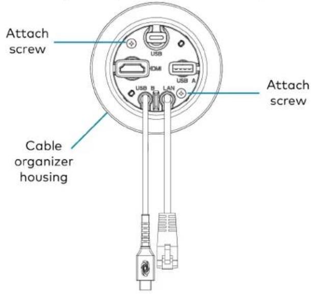
text_image
Attach screw USB HDMI USB A USB B LAN Attach screw Cable organizer housing- Above the mounting surface, pull all of the cables out to the needed length. Ensure that there is a least 2 in. (51 mm) of cable slack beneath the mounting surface, and attach a cable tie to each cable. Trim the cable ties as needed and push the cables back to the cable organizer plate.
NOTE: The cable ties prevent overextension by catching on the bottom of the cable organizer plate when the cable is pulled to its maximum length. The added slack ensures that the cables will not disconnect from the UC-PR.

text_image
Attach cable tie wraps (x5)Connect Devices
Connect devices using the cables routed through the cable organizer, as described in the system's Quick Start guide. Scan or click one of the following QR codes to view the system's Quick Start guide.
Mounting CCS-UCA-MIC
The CCS-UCA-MIC extension microphone pod can be placed on the conference table or any flat surface.
Connections
UC-B30-Z and UC-B30-Z-WM Connections
Minimum Requirements
Ensure that the below requirements are met prior to setting up the system.
- A video display (not included) connected to the UC Engine. A second or third display is optional.
- A Zoom Rooms account or activation code (not included).
NOTE: Unless otherwise indicated in this section, the connection procedure is the same for UC-B30-Z and UC-B30-Z-WM.
Identify the UC Bracket Assembly
The UC Bracket Assembly is available in two models. Identify the model included with your Crestron Flex system. Tap or click the corresponding image below to navigate to the appropriate connection instructions.
UC Bracket Assembly with HD-CONV-USB-200 UC Bracket Assembly with HD-CONV-USB-300
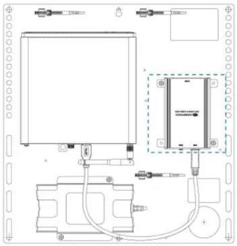
natural_image
Technical line drawing of a mechanical or electrical assembly with no visible text, numbers, or symbols.
text_image
ONION ELECTRIC POWER TO AIR SWITCHER AIRSSystem Overview
For UC Bracket Assembly with HD-CONV-USB-200
When connections are complete, the system appears as shown below. Refer to Make Connections on page 345 for detailed connection instructions.
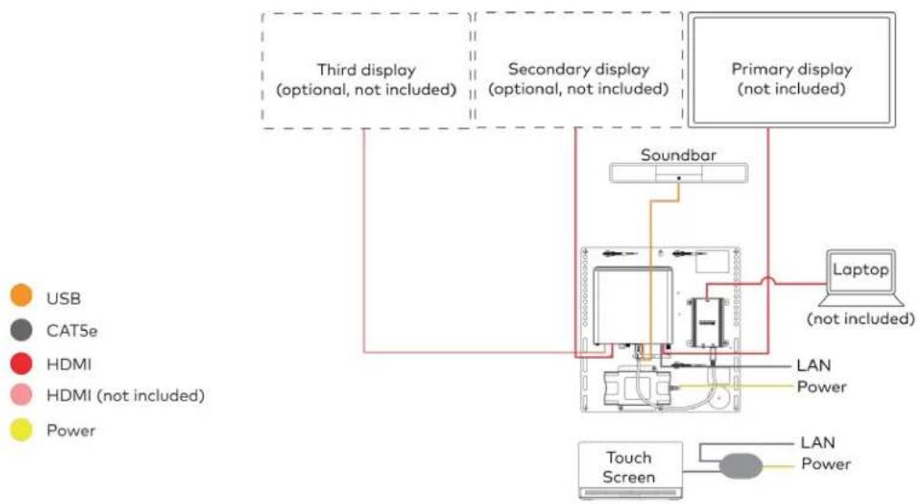
flowchart
graph TD
    A["Third display (optional, not included)"] --> B["Soundbar"]
    C["Secondary display (optional, not included)"] --> B
    D["Primary display (not included)"] --> B
    B --> E["Laptop (not included)"]
    B --> F["LAN Power"]
    B --> G["Touch Screen"]
    style A fill:#f9f,stroke:#333
    style C fill:#f9f,stroke:#333
    style D fill:#f9f,stroke:#333
    style B fill:#ccf,stroke:#333
    style E fill:#cfc,stroke:#333
    style F fill:#fcc,stroke:#333
    style G fill:#cff,stroke:#333
For UC Bracket Assembly with HD-CONV-USB-300
When connections are complete, the system appears as shown below. Refer to Make Connections on page 345 for detailed connection instructions.
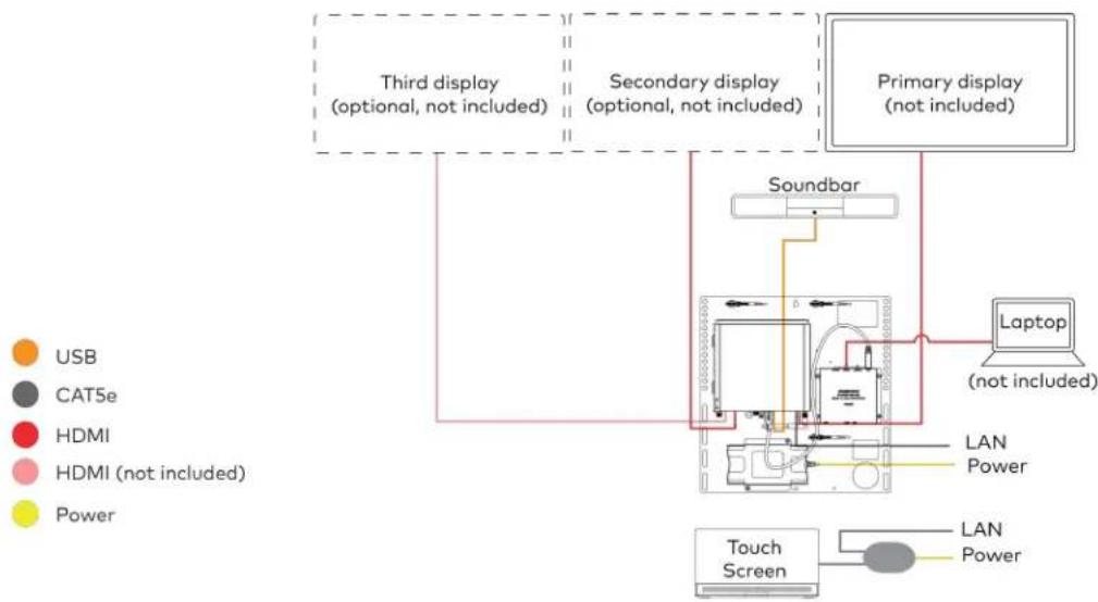
flowchart
graph TD
    A["Third display (optional, not included)"] --> B["Soundbar"]
    C["Secondary display (optional, not included)"] --> B
    D["Primary display (not included)"] --> B
    B --> E["Laptop (not included)"]
    B --> F["LAN Power"]
    F --> G["Touch Screen"]
    H["USB"] --> B
    I["CAT5e"] --> B
    J["HDMI"] --> B
    K["HDMI (not included)"] --> B
    L["Power"] --> B
NOTE: For reference, the UC Bracket Assembly is shown with the HD-CONV-USB-200 in the following connection diagrams. Unless otherwise indicated in this guide, the connections remain the same for the UC Bracket Assembly with HD-CONV-USB-200 and HD-CONV-USB-300.
- Make UC Engine and touch screen connections as shown in the following illustration.

flowchart
graph TD
    A["UC Engine"] --> B["Preconnected"]
    B --> C["Tabletop Touch Screen"]
    C --> D["Wall Mount Touch Screen"]
    D --> E["or"]
    E --> F["PoE Injector"]
    F --> G["POE Injector"]
    G --> H["UC Bracket Assembly"]
    I["CAT5e 7 ft (2.1 m) CAT5e cable (x2) 5 ft (1.5 m) CAT5e cable (supplied with PoE Injector)"] --> J["Power PoE Injector"]
- Connect displays to the UC Engine.

text_image
UC Engine Third display (optional, not included) Secondary display (optional, not included) Primary display (not included) HDMI Primary: 6 ft (1.8 m) HDMI cable Secondary: 6 ft (1.8 m) DisplayPort to HDMI cable Third: DisplayPort to HDMI cable (not included)- Connect the soundbar to the UC Engine as shown in the image below. Do not connect the soundbar to any of the other USB ports.

text_image
UC Engine Power supply Soundbar HD-CONV-USB-200 or HD-CONV-USB-300 (preconnected) USB 6 ft (1.8 m) USB 3.0, A-B Power Power supply- Connect a laptop to the HD-CONV-USB-200 or HD-CONV-USB-300.
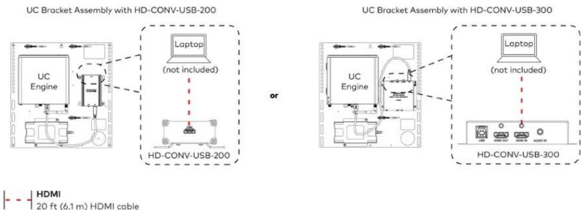
text_image
UC Bracket Assembly with HD-CONV-USB-200 Laptop (not included) HD-CONV-USB-200 or UC Bracket Assembly with HD-CONV-USB-300 Laptop (not included) HD-CONV-USB-300 HDMI 20 ft (6.1 m) HDMI cable- Bundle the cables to the bracket assembly with the integrated cable tie wraps. The cable tie wraps are reusable.
Apply Power
Press the power button on the bottom of the UC Engine and apply power to all of the other devices in the system. The connected display device will show a pairing code.
Log In to the Zoom Rooms Service
-
Tap Touch Here to Enable a Specific Application on the bottom of the screen. A list of applications is displayed.
-
Tap Zoom Rooms and then tap Confirm. The touch screen will reboot.
-
Enter the pairing code shown on the display to pair the touch screen with the UC Engine. The Zoom Rooms controller app is displayed.
-
Log in to the Zoom Rooms service with an activation code or Zoom Rooms Credentials (email and password).
- Activation Code:
a. Tap Enter Activation Code.
b. Enter the 16-digit activation code provided by the administrator to activate the Zoom Room that is assigned to the activation code. The Zoom Rooms Conference Room screen is shown on the display.
- Sign In:
a. Tap Sign In.
b. Enter the Zoom Room credentials and tap Sign In.
c. Select the conference room name from the list and tap Next. The Zoom Rooms Conference Room screen is shown on the display.
- Tap Settings. If a password is required, enter the password (the default password is "1234"). The Settings screen is displayed.
- Tap Microphone and select the soundbar as the source.
- Tap Speaker and select the soundbar as the source.
- Tap Meet Now to exit.
Configure the System
Connect a USB keyboard and mouse (sold separately) to a USB port on the UC Engine to configure system features, as described in Configuration on page 438. For detailed information on using Zoom Rooms, refer to the Zoom Rooms Help Center.
UC-BX30-Z and UC-BX30-Z-WM Connections
Minimum Requirements
Ensure that the below requirements are met prior to setting up the system.
- A video display (not included) connected to the UC Engine. A second or third display is optional.
- A Zoom Rooms account or activation code (not included).
NOTE: Unless otherwise indicated in this section, the connection procedure is the same for UC-BX30-Z and UC-BX30-Z-WM.
System Overview
When connections are complete, the system appears as shown below. The laptop connections shown below may vary based on the selected connection method. Refer to Make Connections on page 349 for detailed connection instructions.
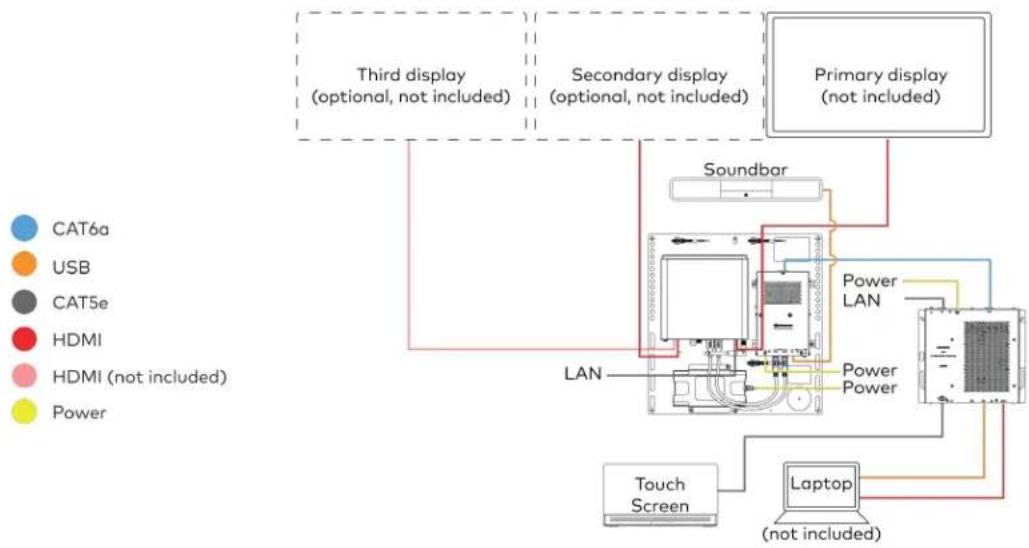
flowchart
graph TD
    A["Primary display (not included)"] --> B["Soundbar"]
    B --> C["LAN"]
    C --> D["Laptop (not included)"]
    D --> E["Touch Screen"]
    E --> F["Power LAN"]
    F --> G["Power Power"]
    G --> H["HDMI (not included)"]
    H --> I["USB"]
    I --> J["CAT6a"]
    style A fill:#f9f,stroke:#333
    style B fill:#ccf,stroke:#333
    style C fill:#cfc,stroke:#333
    style D fill:#fcc,stroke:#333
    style E fill:#cff,stroke:#333
    style F fill:#ffc,stroke:#333
    style G fill:#fcc,stroke:#333
    style H fill:#ffc,stroke:#333
    style I fill:#fcc,stroke:#333
Make Connections
- Make UC Engine connections as shown in the following illustration.

flowchart
graph TD
    A["UC Engine"] -->|Preconnected| B["Preconnected"]
    B --> C["Third display (optional, not included)"]
    B --> D["Secondary display (optional, not included)"]
    B --> E["Primary display (not included)"]
    F["HDMI"] --> G["3rd DisplayPort to HDMI cable (not included)"]
    H["CAT5e 7 ft (2.1 m) CAT5e cable"] --> A
    I["Power UC Bracket Assembly"] --> B
    J["LAN"] --> B
- Connect the power supply and the soundbar to the bottom of the content ingest device (HD-CONV-USB-260). Connect the power supplies to an AC power outlet.
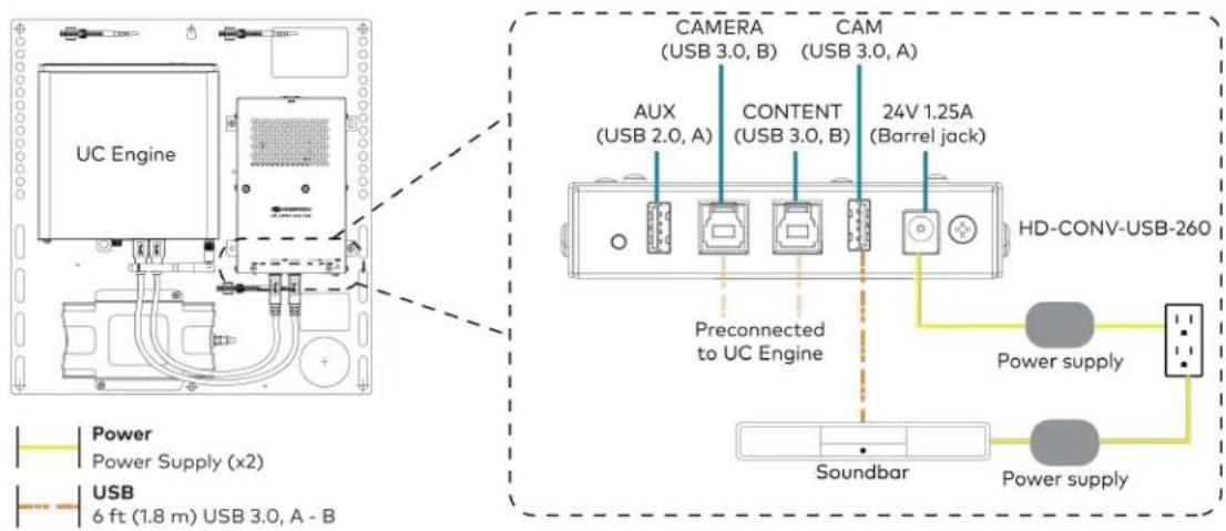
text_image
UC Engine CAMERA (USB 3.0, B) CAM (USB 3.0, A) AUX (USB 2.0, A) CONTENT (USB 3.0, B) 24V 1.25A (Barrel jack) Preconnected to UC Engine HD-CONV-USB-260 Power supply Soundbar Power supply Power Power Supply (x2) USB 6 ft (1.8 m) USB 3.0, A - B- Connect power, the content ingest device (HD-CONV-USB-260), and LAN to the top of the UC Presentation Transmitter.
NOTE: If a longer cable between the UC Presentation Transmitter and the HD-CONV-USB-260 is needed, use a DigitalMedia™ Ultra cable only. The maximum supported cable length is 300 ft (91.4 m).

text_image
UC Presentation Transmitter Tn KE 24V mm 0.5A PWR LAN CAT5e 7 ft (2.1 m) CAT5e cable CAT6a 20 ft (6.1 m) CAT6a patch cable Power UC Presentation Transmitter HD-CONV-USB-260 LAN- Connect the touch screen to the bottom of the UC Presentation Transmitter.

text_image
CAT5e 7 ft (2.1 m) CAT5e cable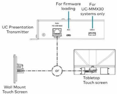
text_image
For firmware loading For UC-MMX30 systems only UC Presentation Transmitter Polo+ F2E 30W MAX ACC USB A or Wall Mount Touch Screen Tabletop Touch screen- Connect a laptop to either the USB port or both the HDMI and USB B ports on the bottom of the UC Presentation Transmitter. Select a connection type based on the available ports on the user's laptop.
NOTE: If the USB port is used along with either the HDMI or USB B port, the UC Presentation Transmitter will communicate via the USB port by default.

text_image
UC Presentation Transmitter or Laptop (not included) UC Presentation Transmitter Laptop (not included) HDMI 6.56 ft (2 m) HDMI cable (for BYOD functionality) USB 6.56 ft (2 m) USB A - Micro B cable 6.56 ft (2 m) USB cable (both for BYOD functionality)- Bundle the cables to the bracket assembly with the integrated cable tie wraps. The cable tie wraps are reusable.
Apply Power
Press the power button on the bottom of the UC Engine and apply power to all of the other devices in the system. The connected display device will show a pairing code.
Log In to the Zoom Rooms Service
-
Tap Touch Here to Enable a Specific Application on the bottom of the screen. A list of applications is displayed.
-
Tap Zoom Rooms and then tap Confirm. The touch screen will reboot.
-
Enter the pairing code shown on the display to pair the touch screen with the UC Engine. The Zoom Rooms controller app is displayed.
-
Log in to the Zoom Rooms service with an activation code or Zoom Rooms Credentials (email and password).
- Activation Code:
a. Tap Enter Activation Code.
b. Enter the 16-digit activation code provided by the administrator to activate the Zoom Room that is assigned to the activation code. The Zoom Rooms Conference Room screen is shown on the display.
- Sign In:
a. Tap Sign In.
b. Enter the Zoom Room credentials and tap Sign In.
c. Select the conference room name from the list and tap Next. The Zoom Rooms Conference Room screen is shown on the display.
-
Tap Settings. If a password is required, enter the password (the default password is "1234"). The Settings screen is displayed.
-
Tap Microphone and select the soundbar as the source.
-
Tap Speaker and select the soundbar as the source.
-
Tap Meet Now to exit.
Configure the System
Connect a USB keyboard and mouse (sold separately) to a USB port on the UC Engine to configure system features, as described in Configuration on page 438. For detailed information on using Zoom Rooms, refer to the Zoom Rooms Help Center.
UC-B31-Z and UC-B31-Z-WM Connections
Minimum Requirements
Ensure that the below requirements are met prior to setting up the system.
- A video display (not included) connected to the UC Engine. A second or third display is optional.
- A Zoom Rooms account or activation code (not included).
NOTE: Unless otherwise indicated in this section, the connection procedure is the same for UC-B31-Z and UC-B31-Z-WM.
Identify the UC Bracket Assembly
The UC Bracket Assembly is available in two models. Identify the model included with your Crestron Flex system. Tap or click the corresponding image below to navigate to the appropriate connection instructions.
UC Bracket Assembly with HD-CONV-USB-200 UC Bracket Assembly with HD-CONV-USB-300

natural_image
Technical line drawing of a mechanical or electrical assembly with no visible text, numbers, or symbols.
text_image
Technical schematic diagram of a device with labeled components and wiring connectionsSystem Overview
For UC Bracket Assembly with HD-CONV-USB-200
When connections are complete, the system appears as shown below. Refer to Make Connections on page 355 for detailed connection instructions.
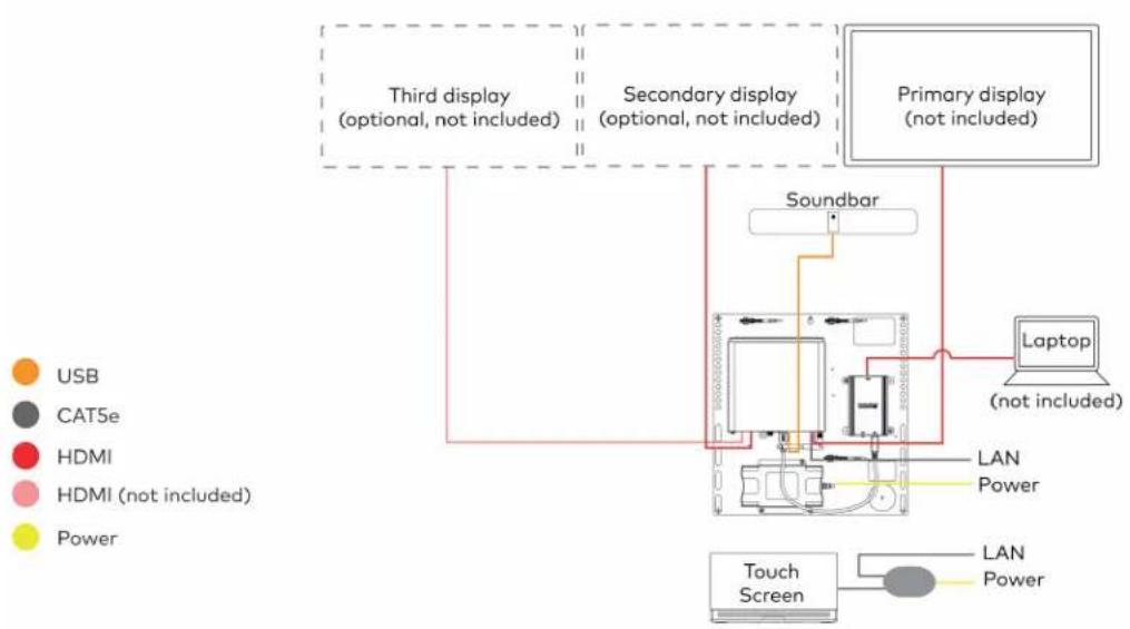
flowchart
graph TD
    A["Third display (optional, not included)"] --> B["Soundbar"]
    C["Secondary display (optional, not included)"] --> B
    D["Primary display (not included)"] --> E["Laptop (not included)"]
    F["Touch Screen"] --> G["LAN Power"]
    H["USB"] --> I["Soundbar"]
    J["CATSe"] --> K["Soundbar"]
    L["HDMI"] --> M["Soundbar"]
    N["HDMI (not included)"] --> O["Soundbar"]
    P["Power"] --> Q["Soundbar"]
    R["Power"] --> S["Soundbar"]
    T["Power"] --> U["Soundbar"]
    V["Power"] --> W["Soundbar"]
    X["Power"] --> Y["Soundbar"]
For UC Bracket Assembly with HD-CONV-USB-300
When connections are complete, the system appears as shown below. Refer to Make Connections on page 355 for detailed connection instructions.
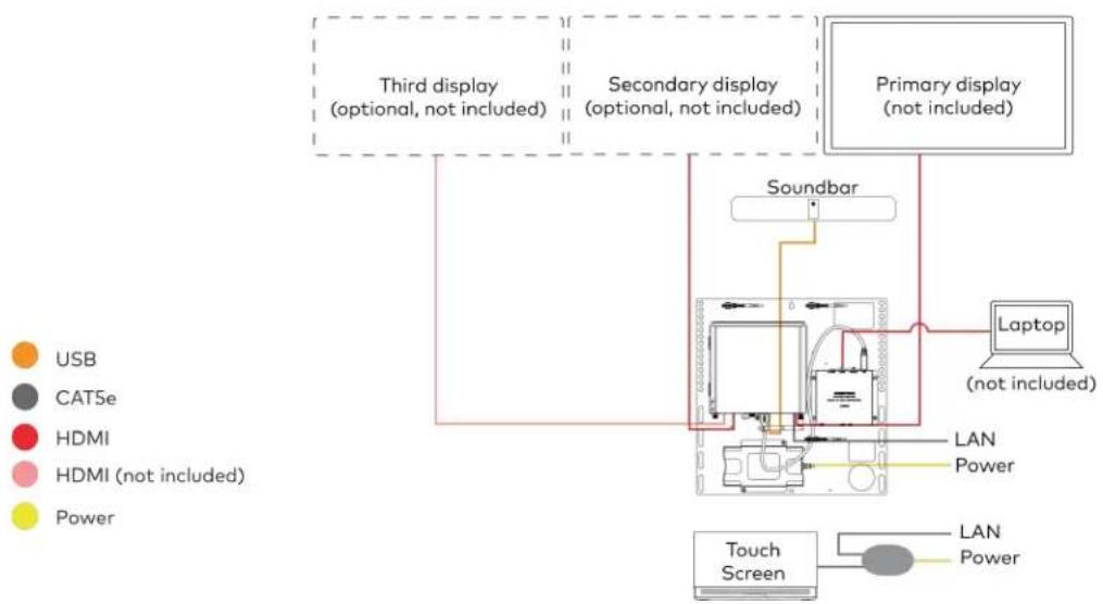
flowchart
graph TD
    A["Third display (optional, not included)"] --> B["Soundbar"]
    C["Secondary display (optional, not included)"] --> B
    D["Primary display (not included)"] --> E["Laptop (not included)"]
    B --> F["Touch Screen"]
    E --> F
    style A fill:#f9f,stroke:#333
    style C fill:#f9f,stroke:#333
    style D fill:#ccf,stroke:#333
    style B fill:#cff,stroke:#333
    style E fill:#ffc,stroke:#333
    style F fill:#cfc,stroke:#333
NOTE: For reference, the UC Bracket Assembly is shown with the HD-CONV-USB-200 in the following connection diagrams. Unless otherwise indicated in this guide, the connections remain the same for the UC Bracket Assembly with HD-CONV-USB-200 and HD-CONV-USB-300.
- Make UC Engine and touch screen connections as shown in the following illustration.

flowchart
graph TD
    A["UC Engine"] --> B["Preconnected"]
    B --> C["Tabletop Touch Screen"]
    C --> D["Wall Mount Touch Screen"]
    D --> E["or"]
    E --> F["PoE Injector"]
    F --> G["POE Injector"]
    G --> H["UC Bracket Assembly"]
    I["CAT5e 7 ft (2.1 m) CAT5e cable (x2) 5 ft (1.5 m) CAT5e cable (supplied with PoE Injector)"] --> J["Power PoE Injector"]
- Connect displays to the UC Engine.

text_image
UC Engine Third display (optional, not included) Secondary display (optional, not included) Primary display (not included) HDMI Primary: 6 ft (1.8 m) HDMI cable Secondary: 6 ft (1.8 m) DisplayPort to HDMI cable Third: DisplayPort to HDMI cable (not included)- Connect the soundbar to the UC Engine as shown in the image below. Do not connect the soundbar to any of the other USB ports.
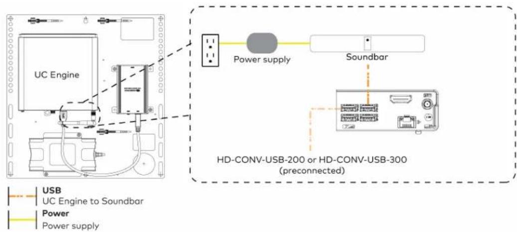
text_image
UC Engine Power supply Soundbar HD-CONV-USB-200 or HD-CONV-USB-300 (preconnected) USB UC Engine to Soundbar Power Power supply- Connect a laptop to the HD-CONV-USB-200 or HD-CONV-USB-300.
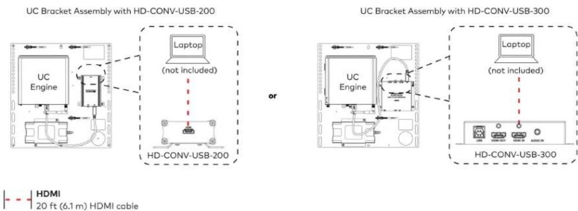
text_image
UC Bracket Assembly with HD-CONV-USB-200 Laptop (not included) HD-CONV-USB-200 or UC Bracket Assembly with HD-CONV-USB-300 Laptop (not included) HD-CONV-USB-300 HDMI 20 ft (6.1 m) HDMI cable- Bundle the cables to the bracket assembly with the integrated cable tie wraps. The cable tie wraps are reusable.
Apply Power
Press the power button on the bottom of the UC Engine and apply power to all of the other devices in the system.
Log In to the Zoom Rooms Service
- Tap Touch Here to Enable a Specific Application on the bottom of the screen. A list of applications is displayed.
- Tap Zoom Rooms and then tap Confirm. The touch screen will reboot.
-
Enter the pairing code shown on the display to pair the touch screen with the UC Engine. The Zoom Rooms controller app is displayed.
-
Log in to the Zoom Rooms service with an activation code or Zoom Rooms Credentials (email and password).
- Activation Code:
a. Tap Enter Activation Code.
b. Enter the 16-digit activation code provided by the administrator to activate the Zoom Room that is assigned to the activation code. The Zoom Rooms Conference Room screen is shown on the display.
- Sign In:
a. Tap Sign In.
b. Enter the Zoom Room credentials and tap Sign In.
c. Select the conference room name from the list and tap Next. The Zoom Rooms Conference Room screen is shown on the display.
- Tap Settings. If a password is required, enter the password (the default password is "1234"). The Settings screen is displayed.
- Tap Microphone and select the as the source.
- Tap Speaker and select the as the source.
- Tap Meet Now to exit.
Configure the System
Connect a USB keyboard and mouse (sold separately) to a USB port on the UC Engine to configure system features, as described in Configuration on page 438. For detailed information on using Zoom Rooms, refer to the Zoom Rooms Help Center.
UC-BX31-Z and UC-BX31-Z-WM Connections
Minimum Requirements
Ensure that the below requirements are met prior to setting up the system.
- A video display (not included) connected to the UC Engine. A second or third display is optional.
- A Zoom Rooms account or activation code (not included).
NOTE: Unless otherwise indicated in this section, the connection procedure is the same for UC-BX31-Z and UC-BX31-Z-WM.
System Overview
When connections are complete, the system appears as shown below. The laptop connections shown below may vary based on the selected connection method. Refer to Make Connections on page 359 for detailed connection instructions.
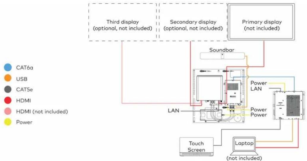
flowchart
graph TD
    A["Primary display (not included)"] --> B["Soundbar"]
    B --> C["LAN"]
    C --> D["Laptop (not included)"]
    D --> E["Touch Screen"]
    E --> F["Power LAN"]
    F --> G["Power Power"]
    G --> H["Secondary display (optional, not included)"]
    H --> I["Third display (optional, not included)"]
    style A fill:#f9f,stroke:#333
    style B fill:#ccf,stroke:#333
    style C fill:#cfc,stroke:#333
    style D fill:#fcc,stroke:#333
    style E fill:#cff,stroke:#333
    style F fill:#ffc,stroke:#333
    style G fill:#cfc,stroke:#333
    style H fill:#fcc,stroke:#333
    style I fill:#ffc,stroke:#333
Make Connections
- Make UC Engine connections as shown in the following illustration.

flowchart
graph TD
    A["UC Engine"] -->|Preconnected| B["Preconnected Device"]
    B --> C["Third display (optional, not included)"]
    B --> D["Secondary display (optional, not included)"]
    B --> E["Primary display (not included)"]
    F["HDMI"] --> G["3rd DisplayPort to HDMI cable (not included)"]
    H["CAT5e 7 ft (2.1 m) CAT5e cable"] --> A
    I["Secondary: 6 ft (1.8 m) DisplayPort to HDMI cable"] --> A
    J["Primary: 6 ft (1.8 m) HDMI cable"] --> A
    K["Secondary: 6 ft (1.8 m) DisplayPort to HDMI cable"] --> A
    L["Primary: 6 ft (1.8 m) HDMI cable"] --> A
    M["Secondary: 6 ft (1.8 m) DisplayPort to HDMI cable"] --> A
    N["Primary: 6 ft (1.8 m) HDMI cable"] --> A
    O["Secondary: 6 ft (1.8 m) HDMI cable"] --> A
    P["Primary: 6 ft (1.8 m) HDMI cable"] --> A
    Q["Secondary: 6 ft (1.8 m) HDMI cable"] --> A
    R["Primary: 6 ft (1.8 m) HDMI cable"] --> A
    S["Secondary: 6 ft (1.8 m) HDMI cable"] --> A
    T["Primary: 6 ft (1.8 m) HDMI cable"] --> A
    U["Secondary: 6 ft (1.8 m) HDMI cable"] --> A
    V["Primary: 6 ft (1.8 m) HDMI cable"] --> A
    W["Secondary: 6 ft (1.8 m) HDMI cable"] --> A
    X["Primary: 6 ft (1.8 m) HDMI cable"] --> A
    Y["Secondary: 6 ft (1.8 m) HDMI cable"] --> A
    Z["Primary: 6 ft (1.8 m) HDMI cable"] --> A
    AA["Secondary: 6 ft (1.8 m) HDMI cable"] --> A
    AB["Primary: 6 ft (1.8 m) HDMI cable"] --> A
    AC["Secondary: 6 ft (1.8 m) HDMI cable"] --> A
    AD["Primary: 6 ft (1.8 m) HDMI cable"] --> A
    AE["Secondary: 6 ft (1.8 m) HDMI cable"] --> A
    AF["Primary: 6 ft (1.8 m) HDMI cable"] --> A
    AG["Secondary: 6 ft (1.8 m) HDMI cable"] --> A
    AH["Primary: 6 ft (1.8 m) HDMI cable"] --> A
    AI["Secondary: 6 ft (1.8 m) HDMI cable"] --> A
    AJ["Primary: 6 ft (1.8 m) HDMI cable"] --> A
    AK["Secondary: 6 ft (1.8 m) HDMI cable"] --> A
    AL["Primary: 6 ft (1.8 m) HDMI cable"] --> A
    AM["Secondary: 6 ft (1.8 m) HDMI cable"] --> A
    AN["Primary: 6 ft (1.8 m) HDMI cable"] --> A
    AO["Secondary: 6 ft (1.8 m) HDMI cable"] --> A
    AP["Primary: 6 ft (1.8 m) HDMI cable"] --> A
    AQ["Secondary: 6 ft (1.8 m) HDMI cable"] --> A
    AR["Primary: 6 ft (1.8 m) HDMI cable"] --> A
    AS["Secondary: 6 ft (1.8 m) HDMI cable"] --> A
    AT["Primary: 6 ft (1.8 m) HDMI cable"] --> A
    AU["Secondary: 6 ft (1.8 m) HDMI cable"] --> A
    AV["Primary: 6 ft (1.8 m) HDMI cable"] --> A
    AW["Secondary: 6 ft (1.8 m) HDMI cable"] --> A
    AX["Primary: 6 ft (1.8 m) HDMI cable"] --> A
    AY["Secondary: 6 ft (1.8 m) HDMI cable"] --> A
    AZ["Primary: 6 ft (1.8 m) HDMI cable"] --> A
    BA["Secondary: 6 ft (1.8 m) HDMI cable"] --> A
    BB["Primary: 6 ft (1.8 m) HDMI cable"] --> A
    BC["Secondary: 6 ft (1.8 m) HDMI cable"] --> A
    BD["Primary: 6 ft (1.8 m) HDMI cable"] --> A
    BE["Secondary: 6 ft (1.8 m) HDMI cable"] --> A
    BF["Primary: 6 ft (1.8 m) HDMI cable"] --> A
    BG["Secondary: 6 ft (1.8 m) HDMI cable"] --> A
    BH["Primary: 6 ft (1.8 m) HDMI cable"] --> A
    BI["Secondary: 6 ft (1.8 m) HDMI cable"] --> A
    BJ["Primary: 6 ft (1.8 m) HDMI cable"] --> A
    BK["Secondary: 6 ft (1.8 m) HDMI cable"] --> A
    BL["Primary: 6 ft (1.8 m) HDMI cable"] --> A
    BM["Secondary: 6 ft (1.8 m) HDMI cable"] --> A
    BN["Primary: 6 ft (1.8 m) HDMI cable"] --> A
    BO["Secondary: 6 ft (1.8 m) HDMI cable"] --> A
    BP["Primary: 6 ft (1.8 m) HDMI cable"] --> A
    BQ["Secondary: 6 ft (1.8 m) HDMI cable"] --> A
    BR["Primary: 6 ft (1.8 m) HDMI cable"] --> A
    CA["Secondary: 6 ft (1.8 m) HDMI cable"] --> A
    CB["Primary: 6 ft (1.8 m) HDMI cable"] --> A
    CC["Secondary: 6 ft (1.8 m) HDMI cable"] --> A
    CD["Primary: 6 ft (1.8 m) HDMI cable"] --> A
    CE["Secondary: 6 ft (1.8 m) HDMI cable"] --> A
    CF["Primary: 6 ft (1.8 m) HDMI cable"] --> A
    GD["Secondary: 6 ft (1.8 m) HDMI cable"] --> A
    DH["Primary: 6 ft (1.8 m) HDMI cable"] --> A
    DI["Secondary: 6 ft (1.8 m) HDMI cable"] --> A
    DJ["Primary: 6 ft (1.8 m) HDMI cable"] --> A
    DK["Secondary: 6 ft (1.8 m) HDMI cable"] --> A
    DL["Primary: 6 ft (1.8 m) HDMI cable"] --> A
    EM["Secondary: 6 ft (1.8 m) HDMI cable"] --> A
    FN["Primary: 6 ft (1.8 m) HDMI cable"] --> A
- Connect the to the bottom of the content ingest device. Connect the power to an AC power outlet.
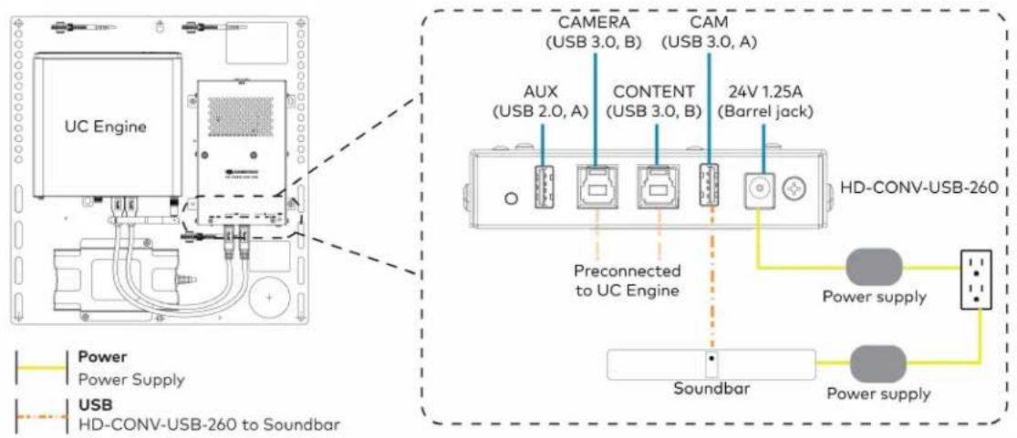
text_image
UC Engine CAMERA (USB 3.0, B) CAM (USB 3.0, A) AUX (USB 2.0, A) CONTENT (USB 3.0, B) 24V 1.25A (Barrel jack) Preconnected to UC Engine HD-CONV-USB-260 Power supply Soundbar Power supply Power Power Supply USB HD-CONV-USB-260 to Soundbar- Connect power, the content ingest device (HD-CONV-USB-260), and LAN to the top of the UC Presentation Transmitter.
NOTE: If a longer cable between the UC Presentation Transmitter and the HD-CONV-USB-260 is needed, use a DigitalMedia™ Ultra cable only. The maximum supported cable length is 300 ft (91.4 m).

text_image
CAT5e 7 ft (2.1 m) CAT5e cable CAT6a 20 ft (6.1 m) CAT6a patch cable Power UC Presentation Transmitter UC Presentation Transmitter To XX 34V mm 4.0A PWR LAN LAN HD-CONV-USB-260- Connect the touch screen to the bottom of the UC Presentation Transmitter.

text_image
CAT5e 7 ft (2.1 m) CAT5e cable
text_image
For firmware loading For UC-MMX30 systems only UC Presentation Transmitter Polo+ F2E 30W MAX ACC USB A or Wall Mount Touch Screen Tabletop Touch screen- Connect a laptop to either the USB port or both the HDMI and USB B ports on the bottom of the UC Presentation Transmitter. Select a connection type based on the available ports on the user's laptop.
NOTE: If the USB port is used along with either the HDMI or USB B port, the UC Presentation Transmitter will communicate via the USB port by default.

text_image
UC Presentation Transmitter or Laptop (not included) UC Presentation Transmitter Laptop (not included) HDMI 6.56 ft (2 m) HDMI cable (for BYOD functionality) USB 6.56 ft (2 m) USB A - Micro B cable 6.56 ft (2 m) USB cable (both for BYOD functionality)- Bundle the cables to the bracket assembly with the integrated cable tie wraps. The cable tie wraps are reusable.
Apply Power
Press the power button on the bottom of the UC Engine and apply power to all of the other devices in the system.
Log In to the Zoom Rooms Service
-
Tap Touch Here to Enable a Specific Application on the bottom of the screen. A list of applications is displayed.
-
Tap Zoom Rooms and then tap Confirm. The touch screen will reboot.
-
Enter the pairing code shown on the display to pair the touch screen with the UC Engine. The Zoom Rooms controller app is displayed.
-
Log in to the Zoom Rooms service with an activation code or Zoom Rooms Credentials (email and password).
- Activation Code:
a. Tap Enter Activation Code.
b. Enter the 16-digit activation code provided by the administrator to activate the Zoom Room that is assigned to the activation code. The Zoom Rooms Conference Room screen is shown on the display.
- Sign In:
a. Tap Sign In.
b. Enter the Zoom Room credentials and tap Sign In.
c. Select the conference room name from the list and tap Next. The Zoom Rooms Conference Room screen is shown on the display.
-
Tap Settings. If a password is required, enter the password (the default password is "1234"). The Settings screen is displayed.
-
Tap Microphone and select the as the source.
-
Tap Speaker and select the as the source.
-
Tap Meet Now to exit.
Configure the System
Connect a USB keyboard and mouse (sold separately) to a USB port on the UC Engine to configure system features, as described in Configuration on page 438. For detailed information on using Zoom Rooms, refer to the Zoom Rooms Help Center.
UC-C100-Z and UC-C100-Z-WM Connections
Minimum Requirements
Ensure that the below requirements are met prior to setting up the system.
• A certified USB Camera (not included).
• A certified, AEC-enabled USB speakerphone or DSP device (not included).
- A video display (not included) connected to the UC Engine. A second or third display is optional.
- A Zoom Rooms account or activation code (not included).
NOTE: Unless otherwise indicated in this section, the connection procedure is the same for UC-C100-Z and UC-C100-Z-WM.
Identify the UC Bracket Assembly
The UC Bracket Assembly is available in two models. Identify the model included with your Crestron Flex system. Tap or click the corresponding image below to navigate to the appropriate connection instructions.
UC Bracket Assembly with HD-CONV-USB-200 UC Bracket Assembly with HD-CONV-USB-300
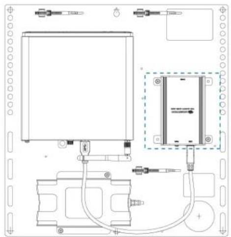
natural_image
Technical line drawing of a mechanical or electrical assembly with no visible text, numbers, or symbols.
text_image
Technical schematic diagram of a device with labeled components and wiring connectionsSystem Overview
For UC Bracket Assembly with HD-CONV-USB-200
When connections are complete, the system appears as shown below. Refer to Make Connections on page 365 for detailed connection instructions.

flowchart
graph TD
    A["Primary display (not included)"] --> B["Camera (not included)"]
    B --> C["Laptop (not included)"]
    C --> D["LAN Power"]
    D --> E["USB Audio"]
    D --> F["LAN"]
    E --> G["Touch Screen"]
    F --> G
    style A fill:#f9f,stroke:#333
    style B fill:#ccf,stroke:#333
    style C fill:#cfc,stroke:#333
    style D fill:#fcc,stroke:#333
    style E fill:#ffc,stroke:#333
    style F fill:#fcc,stroke:#333
    style G fill:#cff,stroke:#333
For UC Bracket Assembly with HD-CONV-USB-300
When connections are complete, the system appears as shown below. Refer to Make Connections on page 365 for detailed connection instructions.
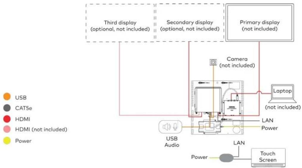
flowchart
graph TD
    A["Primary display (not included)"] --> B["Camera (not included)"]
    B --> C["Laptop (not included)"]
    C --> D["LAN Power"]
    D --> E["USB Audio"]
    E --> F["Touch Screen"]
    G["Third display (optional, not included)"] --> B
    H["Secondary display (optional, not included)"] --> B
    I["Power"] --> E
    J["USB"] --> E
    K["CAT5e"] --> E
    L["HDMI"] --> E
    M["HDMI (not included)"] --> E
    N["Power"] --> E
NOTE: For reference, the UC Bracket Assembly is shown with the HD-CONV-USB-200 in the following connection diagrams. Unless otherwise indicated in this guide, the connections remain the same for the UC Bracket Assembly with HD-CONV-USB-200 and HD-CONV-USB-300.
- Make UC Engine and touch screen connections as shown in the following illustration.
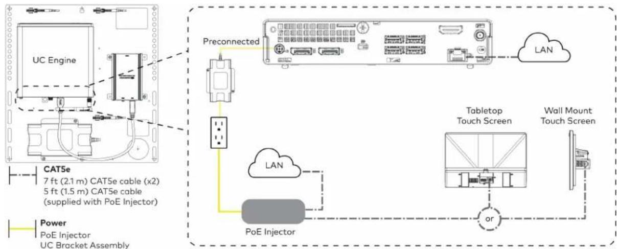
flowchart
graph TD
    A["UC Engine"] -->|Preconnected| B["Preconnected device"]
    B --> C["Tabletop Touch Screen"]
    C --> D["Wall Mount Touch Screen"]
    D --> E["or"]
    E --> F["PoE Injector"]
    F --> G["POE Injector"]
    G --> H["UC Bracket Assembly"]
    I["CAT5e 7 ft (2.1 m) CAT5e cable (x2) 5 ft (1.5 m) CAT5e cable (supplied with PoE Injector)"] --> J["Power PoE Injector"]
- Connect a USB audio source (accessory) and displays to the UC Engine.
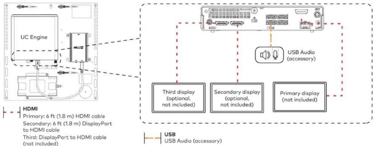
flowchart
graph TD
    A["UC Engine"] --> B["Third DisplayPort to HDMI cable (not included)"]
    A --> C["Secondary DisplayPort to HDMI cable (not included)"]
    A --> D["Third display (optional, not included)"]
    A --> E["Secondary display (optional, not included)"]
    A --> F["Primary display (not included)"]
    G["USB Audio (accessory)"] --> H["USB Audio (accessory)"]
    style A fill:#f9f,stroke:#333
    style B fill:#ccf,stroke:#333
    style C fill:#cfc,stroke:#333
    style D fill:#fcc,stroke:#333
    style E fill:#cff,stroke:#333
    style F fill:#ffc,stroke:#333
- Connect a camera (not included) to the UC Engine as shown in the image below. Do not connect the camera to any of the other USB ports.
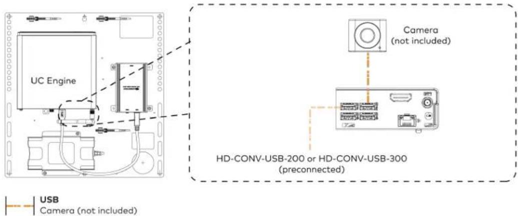
text_image
UC Engine Camera (not included) HD-CONV-USB-200 or HD-CONV-USB-300 (preconnected) USB Camera (not included)- Connect a laptop to the HD-CONV-USB-200 or HD-CONV-USB-300.

text_image
UC Bracket Assembly with HD-CONV-USB-200 Laptop (not included) or UC Bracket Assembly with HD-CONV-USB-300 UC Engine UC Engine (not included) Laptop (HDMI 20 ft (6.1 m) HDMI cable)- Bundle the cables to the bracket assembly with the integrated cable tie wraps. The cable tie wraps are reusable.
Apply Power
Press the power button on the bottom of the UC Engine and apply power to all of the other devices in the system. The connected display device will show a pairing code.
Log In to the Zoom Rooms Service
-
Tap Touch Here to Enable a Specific Application on the bottom of the screen. A list of applications is displayed.
-
Tap Zoom Rooms and then tap Confirm. The touch screen will reboot.
-
Enter the pairing code shown on the display to pair the touch screen with the UC Engine. The Zoom Rooms controller app is displayed.
-
Log in to the Zoom Rooms service with an activation code or Zoom Rooms Credentials (email and password).
- Activation Code:
a. Tap Enter Activation Code.
b. Enter the 16-digit activation code provided by the administrator to activate the Zoom Room that is assigned to the activation code. The Zoom Rooms Conference Room screen is shown on the display.
- Sign In:
a. Tap Sign In.
b. Enter the Zoom Room credentials and tap Sign In.
c. Select the conference room name from the list and tap Next. The Zoom Rooms Conference Room screen is shown on the display.
- Tap Settings. If a password is required, enter the password (the default password is "1234"). The Settings screen is displayed.
- Tap Microphone and select the USB audio device as the source.
- Tap Speaker and select the USB audio device as the source.
- Tap Meet Now to exit.
Configure the System
Connect a USB keyboard and mouse (sold separately) to a USB port on the UC Engine to configure system features, as described in Configuration on page 438. For detailed information on using Zoom Rooms, refer to the Zoom Rooms Help Center.
UC-CX100-Z and UC-CX100-Z-WM Connections
Minimum Requirements
Ensure that the below requirements are met prior to setting up the system.
• A certified USB Camera (not included).
- A certified, AEC-enabled USB speakerphone or DSP device (not included).
- A video display (not included) connected to the UC Engine. A second or third display is optional.
- A Zoom Rooms account or activation code (not included).
NOTE: Unless otherwise indicated in this section, the connection procedure is the same for UC-CX100-Z and UC-CX100-Z-WM.
System Overview
When connections are complete, the system appears as shown below. The laptop connections shown below may vary based on the selected connection method. Refer to Make Connections on page 369 for detailed connection instructions.

flowchart
graph TD
    A["Primary display (not included)"] --> B["Camera (not included)"]
    B --> C["LAN"]
    C --> D["USB Audio"]
    C --> E["Touch Screen"]
    C --> F["Laptop (not included)"]
    G["Secondary display (optional, not included)"] --> H["Camera (not included)"]
    I["Third display (optional, not included)"] --> J["Camera (not included)"]
    K["Power"] --> L["Power LAN"]
    M["HDMI (not included)"] --> N["Power Power"]
    O["USB"] --> P["Camera"]
    Q["CAT6a"] --> R["Camera"]
    S["USB"] --> T["Camera"]
    U["CAT5e"] --> V["Camera"]
    W["HDMI"] --> X["Camera"]
    Y["HDMI (not included)"] --> Z["Camera"]
    AA["Power"] --> AB["Camera"]
Make Connections
- Make UC Engine connections as shown in the following illustration.

flowchart
graph TD
    A["UC Engine"] -->|Preconnected| B["Preconnected Device"]
    B --> C["Third display (optional, not included)"]
    B --> D["Secondary display (optional, not included)"]
    B --> E["Primary display (not included)"]
    F["HDMI"] --> G["3rd DisplayPort to HDMI cable (not included)"]
    G --> H["TCAT5e 7 ft (2.1 m) CAT5e cable"]
    G --> I["Secondary 6 ft (1.8 m) DisplayPort to HDMI cable"]
    G --> J["TCAT5e 7 ft (2.1 m) CAT5e cable"]
    K["LAN"] --> L["Central PC"]
    L --> M["Power UC Bracket Assembly"]
- Connect the power supply, USB audio (accessory), and a camera (not included) to the bottom of the content ingest device (HD-CONV-USB-260). Connect the power supply to an AC power outlet.
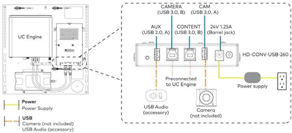
text_image
UC Engine CAMERA (USB 3.0, B) CAM (USB 3.0, A) AUX (USB 2.0, A) CONTENT (USB 3.0, B) 24V 1.25A (Barrel jack) Preconnected to UC Engine HD-CONV-USB-260 Power supply USB Audio (accessory) Camera (not included) USB Camera (not included) USB Audio (accessory)- Connect power, the content ingest device (HD-CONV-USB-260), and LAN to the top of the UC Presentation Transmitter.
NOTE: If a longer cable between the UC Presentation Transmitter and the HD-CONV-USB-260 is needed, use a DigitalMedia™ Ultra cable only. The maximum supported cable length is 300 ft (91.4 m).

text_image
UC Presentation Transmitter To 8X 24G 6.0A PWR LAN CAT5e 7 ft (2.1 m) CAT5e cable CAT6a 20 ft (6.1 m) CAT6a patch cable Power UC Presentation Transmitter HD-CONV-USB-260 LAN- Connect the touch screen to the bottom of the UC Presentation Transmitter.

text_image
CAT5e 7 ft (2.1 m) CAT5e cable
text_image
For firmware loading For UC-MMX30 systems only UC Presentation Transmitter Polo+ F2E 30W MAX ACC USB A or Wall Mount Touch Screen Tabletop Touch screen- Connect a laptop to either the USB port or both the HDMI and USB B ports on the bottom of the UC Presentation Transmitter. Select a connection type based on the available ports on the user's laptop.
NOTE: If the USB port is used along with either the HDMI or USB B port, the UC Presentation Transmitter will communicate via the USB port by default.

text_image
UC Presentation Transmitter or Laptop (not included) UC Presentation Transmitter Laptop (not included) HDMI 6.56 ft (2 m) HDMI cable (for BYOD functionality) USB 6.56 ft (2 m) USB A - Micro B cable 6.56 ft (2 m) USB cable (both for BYOD functionality)- Bundle the cables to the bracket assembly with the integrated cable tie wraps. The cable tie wraps are reusable.
Apply Power
Press the power button on the bottom of the UC Engine and apply power to all of the other devices in the system. The connected display device will show a pairing code.
Log In to the Zoom Rooms Service
-
Tap Touch Here to Enable a Specific Application on the bottom of the screen. A list of applications is displayed.
-
Tap Zoom Rooms and then tap Confirm. The touch screen will reboot.
-
Enter the pairing code shown on the display to pair the touch screen with the UC Engine. The Zoom Rooms controller app is displayed.
-
Log in to the Zoom Rooms service with an activation code or Zoom Rooms Credentials (email and password).
- Activation Code:
a. Tap Enter Activation Code.
b. Enter the 16-digit activation code provided by the administrator to activate the Zoom Room that is assigned to the activation code. The Zoom Rooms Conference Room screen is shown on the display.
- Sign In:
a. Tap Sign In.
b. Enter the Zoom Room credentials and tap Sign In.
c. Select the conference room name from the list and tap Next. The Zoom Rooms Conference Room screen is shown on the display.
-
Tap Settings. If a password is required, enter the password (the default password is "1234"). The Settings screen is displayed.
-
Tap Microphone and select the USB audio device as the source.
-
Tap Speaker and select the USB audio device as the source.
-
Tap Meet Now to exit.
Configure the System
Connect a USB keyboard and mouse (sold separately) to a USB port on the UC Engine to configure system features, as described in Configuration on page 438. For detailed information on using Zoom Rooms, refer to the Zoom Rooms Help Center.
UC-MM30-Z and UC-MM30-Z-I Connections
Minimum Requirements
Ensure that the below requirements are met prior to setting up the system.
- A video display (not included) connected to the UC Engine. A second or third display is optional.
- A Zoom Rooms account or activation code (not included).
NOTE: Unless otherwise indicated in this section, the connection procedure is the same for UC-MM30-Z and UC-MM30-Z-I.
Identify the UC Bracket Assembly
The UC Bracket Assembly is available in two models. Identify the model included with your Crestron Flex system. Tap or click the corresponding image below to navigate to the appropriate connection instructions.
UC Bracket Assembly with HD-CONV-USB-200 UC Bracket Assembly with HD-CONV-USB-300

natural_image
Technical line drawing of a mechanical or electrical assembly with no visible text, numbers, or symbols.
text_image
Technical schematic diagram of a device with labeled components and wiring connectionsSystem Overview
For UC Bracket Assembly with HD-CONV-USB-200
When connections are complete, the system appears as shown below. Refer to Make Connections on page 375 for detailed connection instructions.
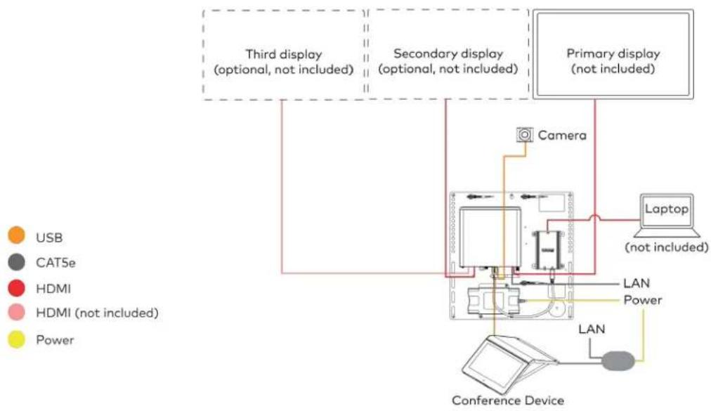
flowchart
graph TD
    A["Third display\n(optional, not included)"] --> B["Camera"]
    C["Secondary display\n(optional, not included)"] --> B
    D["Primary display\n(not included)"] --> B
    B --> E["Laptop\n(not included)"]
    E --> F["LAN"]
    F --> G["Power"]
    G --> H["Conference Device"]
    I["USB"] --> A
    J["CATSe"] --> A
    K["HDMI"] --> A
    L["HDMI (not included)"] --> A
    M["Power"] --> A
    A --> N["Camera"]
    style A fill:#f9f,stroke:#333
    style C fill:#f9f,stroke:#333
    style D fill:#f9f,stroke:#333
    style I fill:#ccf,stroke:#333
    style J fill:#ccf,stroke:#333
    style K fill:#ccf,stroke:#333
    style L fill:#ccf,stroke:#333
    style M fill:#ccf,stroke:#333
For UC Bracket Assembly with HD-CONV-USB-300
When connections are complete, the system appears as shown below. Refer to Make Connections on page 375 for detailed connection instructions.

flowchart
graph TD
    A["Third display\n(optional, not included)"] --> B["Camera"]
    C["Secondary display\n(optional, not included)"] --> B
    D["Primary display\n(not included)"] --> E["Laptop\n(not included)"]
    F["Conference Device"] --> G["LAN"]
    G --> H["Power"]
    I["USB"] --> G
    J["CAT5e"] --> G
    K["HDMI"] --> G
    L["HDMI (not included)"] --> G
    M["Power"] --> G
NOTE: For reference, the UC Bracket Assembly is shown with the HD-CONV-USB-200 in the following connection diagrams. Unless otherwise indicated in this guide, the connections remain the same for the UC Bracket Assembly with HD-CONV-USB-200 and HD-CONV-USB-300.
- Make UC Engine connections as shown in the following illustration.

flowchart
graph TD
    A["UC Engine"] --> B["Preconnected"]
    B --> C["LAN"]
    C --> D["Conference Device"]
    D --> E["PoE Injector"]
    E --> F["Power"]
    style A fill:#f9f,stroke:#333
    style B fill:#ccf,stroke:#333
    style C fill:#cfc,stroke:#333
    style D fill:#fcc,stroke:#333
    style E fill:#ffc,stroke:#333
    style F fill:#fcc,stroke:#333
- Connect displays to the UC Engine.

text_image
UC Engine HDMI Primary: 6 ft (1.8 m) HDMI cable Secondary: 6 ft (1.8 m) DisplayPort to HDMI cable Third: DisplayPort to HDMI cable (not included) Third display (optional, not included) Secondary display (optional, not included) Primary display (not included)- Connect the camera to the UC Engine as shown in the image below. Do not connect the camera to any of the other USB ports.
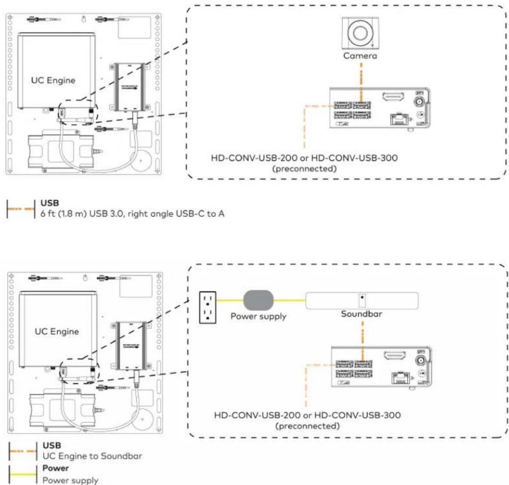
USB 6 ft (1.8 m) USB 3.0, right angle USB-C to A
USB UC Engine to Soundbar Power Power supply
- Connect a laptop to the HD-CONV-USB-200 or HD-CONV-USB-300.

text_image
UC Bracket Assembly with HD-CONV-USB-200 UC Engine Laptop (not included) or HD-CONV-USB-200 UC Bracket Assembly with HD-CONV-USB-300 UC Engine Laptop (not included) or HD-CONV-USB-300HDMI 20 ft (6.1 m) HDMI cable
- Bundle the cables to the bracket assembly with the integrated cable tie wraps. The cable tie wraps are reusable.
Apply Power
Press the power button on the bottom of the UC Engine and apply power to all of the other devices in the system. The connected display device will show a pairing code. The conference device will show a prompt to enter a pairing code.
Log In to the Zoom Rooms Service
Use the conference device to sign in to the Zoom Rooms service using an activation code or a Zoom Room Sign-In.
-
Tap Zoom and then tap OK. The device will reboot.
-
Enter the pairing code shown on the display to pair the device with the UC Engine. The Zoom Rooms controller app is displayed.
-
Log in to the Zoom Rooms service with an activation code or Zoom Rooms Credentials (email and password).
- Activation Code:
a. Tap Enter Activation Code.
b. Enter the 16-digit activation code provided by the IT administrator managing the Zoom portal to activate the Zoom Room assigned to the activation code. The Zoom Rooms Conference Room screen is shown on the display.
- Sign In:
a. Tap Sign In.
b. Enter the Zoom Room credentials and tap Sign In.
c. Select the conference room name from the list and tap Next. The Zoom Rooms Conference Room screen is shown on the display.
-
Tap Settings. If a password is required, enter the password (the default password is "1234"). The Settings screen is displayed.
-
Tap Microphone and select the conference device as the source.
-
Tap Speaker and select the conference device as the source.
-
Tap Meet Now to exit.
Configure the System
Connect a USB keyboard and mouse (sold separately) to a USB port on the UC Engine to configure system features, as described in Configuration on page 438. For detailed information on using Zoom Rooms, refer to the Zoom Rooms Help Center.
Factory Reset
A factory reset may be performed when troubleshooting the conference device.
To perform a factory reset on the conference device:
-
Power cycle the device by disconnecting and reconnecting the CAT5e cable from the conference device.
-
When the device powers on and the LEDs flash green, tap the button below the Crestron® logo 10 times. A factory reset confirmation screen appears.
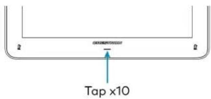
text_image
Tap x10- Tap one of the mute buttons to move the selector on the factory reset confirmation screen to Yes. Tap the button below the Crestron logo to confirm the factory reset.

text_image
Tap to move selector Tap to confirm Tap to move selector- The device will reboot. Configure the device as described in Configure the Conference Device section.
UC-MMX30-Z and UC-MMX30-Z-I Connections
Minimum Requirements
Ensure that the below requirements are met prior to setting up the system.
- A video display (not included) connected to the UC Engine. A second or third display is optional.
- A Zoom Rooms account or activation code (not included).
NOTE: Unless otherwise indicated in this section, the connection procedure is the same for UC-MMX30-Z and UC-MMX30-Z-I.
System Overview
When connections are complete, the system appears as shown below. The laptop connections shown below may vary based on the selected connection method. Refer to Make Connections on page 380 for detailed connection instructions.
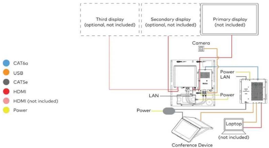
flowchart
graph TD
    A["Third display (optional, not included)"] --> B["Camera"]
    C["Secondary display (optional, not included)"] --> B
    D["Primary display (not included)"] --> B
    E["Conference Device"] --> F["Laptop (not included)"]
    G["Power"] --> H["LAN"]
    I["Power LAN"] --> J["Camera"]
    K["Power"] --> L["LAN"]
    M["Power"] --> N["LAN"]
    O["Power"] --> P["LAN"]
    Q["Power"] --> R["LAN"]
    S["Power"] --> T["LAN"]
    U["Power"] --> V["LAN"]
    W["Power"] --> X["LAN"]
    Y["Power"] --> Z["LAN"]
    style A fill:#f9f,stroke:#333
    style C fill:#f9f,stroke:#333
    style D fill:#f9f,stroke:#333
    style E fill:#ccf,stroke:#333
    style F fill:#cfc,stroke:#333
    style G fill:#fcc,stroke:#333
    style H fill:#cff,stroke:#333
    style I fill:#ffc,stroke:#333
    style J fill:#ffc,stroke:#333
    style K fill:#ffc,stroke:#333
    style L fill:#ffc,stroke:#333
    style M fill:#ffc,stroke:#333
    style N fill:#ffc,stroke:#333
    style O fill:#ffc,stroke:#333
    style P fill:#ffc,stroke:#333
    style Q fill:#ffc,stroke:#333
    style R fill:#ffc,stroke:#333
    style S fill:#ffc,stroke:#333
    style T fill:#ffc,stroke:#333
    style U fill:#ffc,stroke:#333
Make Connections
- Make UC Engine connections as shown in the following illustration.
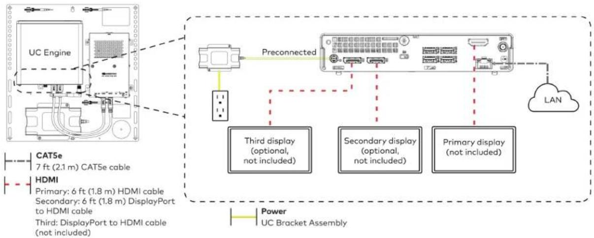
flowchart
graph TD
    A["UC Engine"] -->|Preconnected| B["Preconnected"]
    B --> C["Third display (optional, not included)"]
    B --> D["Secondary display (optional, not included)"]
    B --> E["Primary display (not included)"]
    F["HDMI"] --> G["3rd DisplayPort to HDMI cable (not included)"]
    H["CAT5e 7 ft (2.1 m) CAT5e cable"] --> A
    I["Power UC Bracket Assembly"] --> B
    J["LAN"] --> B
- Connect the power supply and camera to the bottom of the content ingest device (HD-CONV-USB-260). Connect the power supply to an AC power outlet.
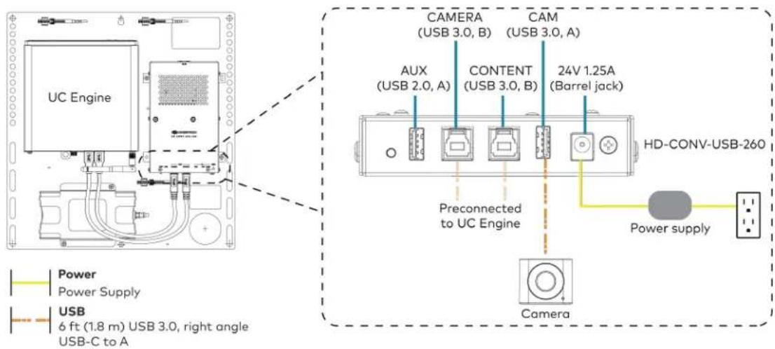
text_image
UC Engine CAMERA (USB 3.0, B) CAM (USB 3.0, A) AUX (USB 2.0, A) CONTENT (USB 3.0, B) 24V 1.25A (Barrel jack) Preconnected to UC Engine HD-CONV-USB-260 Power supply Camera Power Supply USB 6 ft (1.8 m) USB 3.0, right angle USB-C to A- Connect power, the content ingest device (HD-CONV-USB-260), and LAN to the top of the UC Presentation Transmitter.
NOTE: If a longer cable between the UC Presentation Transmitter and the HD-CONV-USB-260 is needed, use a DigitalMedia™ Ultra cable only. The maximum supported cable length is 300 ft (91.4 m).
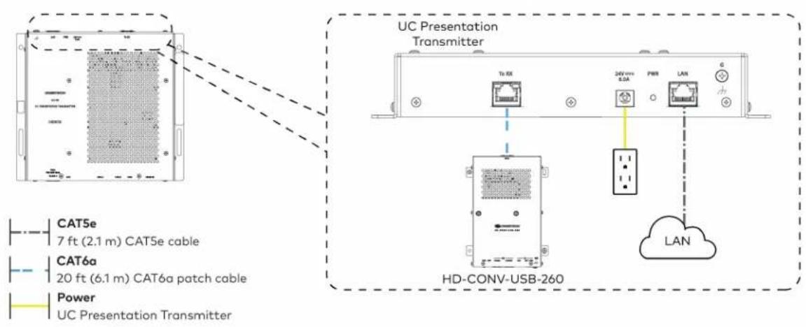
text_image
UC Presentation Transmitter Tb RX 24V mm 8.5A PWR LAN CAT5e 7 ft (2.1 m) CAT5e cable CAT6a 20 ft (6.1 m) CAT6a patch cable Power UC Presentation Transmitter HD-CONV-USB-260 LAN- Connect the conference device using the included PoE+ injector and USB A to Micro-B cable to the bottom of the UC Presentation Transmitter.
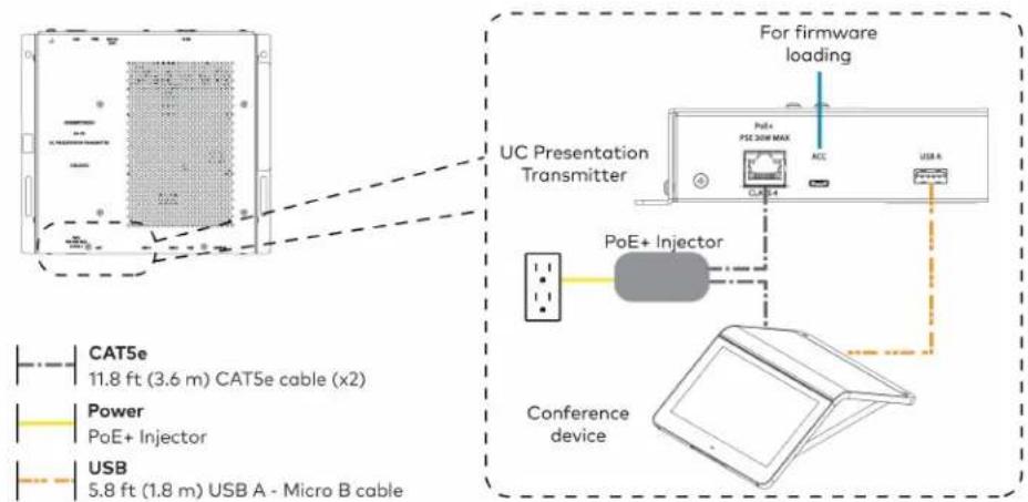
text_image
For firmware loading UC Presentation Transmitter PoE+ PSE 300 MAX ACC USB A PoE+ Injector Conference device CAT5e 11.8 ft (3.6 m) CAT5e cable (x2) Power PoE+ Injector USB 5.8 ft (1.8 m) USB A - Micro B cable- Connect a laptop to either the USB port or both the HDMI and USB B ports on the bottom of the UC Presentation Transmitter. Select a connection type based on the available ports on the user's laptop.
NOTES:
- When connecting a laptop for BYOD presentation, select the audio source on the connected laptop.
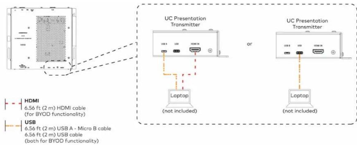
text_image
UC Presentation Transmitter or Laptop (not included) UC Presentation Transmitter Laptop (not included) HDMI 6.56 ft (2 m) HDMI cable (for BYOD functionality) USB 6.56 ft (2 m) USB A - Micro B cable 6.56 ft (2 m) USB cable (both for BYOD functionality)- Bundle the cables to the bracket assembly with the integrated cable tie wraps. The cable tie wraps are reusable.
Apply Power
Press the power button on the bottom of the UC Engine and apply power to all of the other devices in the system.
Log In to the Zoom Rooms Service
Use the conference device to sign in to the Zoom Rooms service using an activation code or a Zoom Room Sign-In.
-
Tap Zoom and then tap OK. The device will reboot.
-
Enter the pairing code shown on the display to pair the device with the UC Engine. The Zoom Rooms controller app is displayed.
-
Log in to the Zoom Rooms service with an activation code or Zoom Rooms Credentials (email and password).
- Activation Code:
a. Tap Enter Activation Code.
b. Enter the 16-digit activation code provided by the IT administrator managing the Zoom portal to activate the Zoom Room assigned to the activation code. The Zoom Rooms Conference Room screen is shown on the display.
- Sign In:
a. Tap Sign In.
b. Enter the Zoom Room credentials and tap Sign In.
c. Select the conference room name from the list and tap Next. The Zoom Rooms Conference Room screen is shown on the display.
-
Tap Settings. If a password is required, enter the password (the default password is "1234"). The Settings screen is displayed.
-
Tap Microphone and select the conference device as the source.
-
Tap Speaker and select the conference device as the source.
-
Tap Meet Now to exit.
Configure the System
Connect a USB keyboard and mouse (sold separately) to a USB port on the UC Engine to configure system features, as described in Configuration on page 438. For detailed information on using Zoom Rooms, refer to the Zoom Rooms Help Center.
Factory Reset
A factory reset may be performed when troubleshooting the conference device.
To perform a factory reset on the conference device:
-
Power cycle the device by disconnecting and reconnecting the CAT5e cable from the conference device.
-
When the device powers on and the LEDs flash green, tap the button below the Crestron® logo 10 times. A factory reset confirmation screen appears.
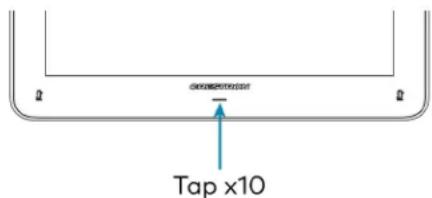
text_image
Tap x10- Tap one of the mute buttons to move the selector on the factory reset confirmation screen to Yes. Tap the button below the Crestron logo to confirm the factory reset.

text_image
Tap to move selector Tap to confirm Tap to move selector- The device will reboot.
UC-M50-Z Connections
Minimum Requirements
Ensure that the below requirements are met prior to setting up the system.
- A video display (not included) connected to the UC Engine. A second display is optional.
- A Zoom Rooms account or activation code (not included).
Install the Cable Retention Plate
The included cable retention plate provides tie-down points for cables that connect to the Crestron® conference device.
Remove the adhesive backing from the cable retention plate and install the plate on the underside of the conference device as shown in the following diagram. Ensure the cable retention plate is firmly attached before securing cables.
CAUTION: When turning over the device, place the device on a soft surface to avoid damage.
NOTE: If a swivel mount kit (CCS-UCA-SMK) is to be used, use the cable retention bracket included with the swivel mount kit as described in the CCS-UCA-SMK DO Guide (Doc. 7882).

text_image
Install cable retention plate here Cable retention plate installedIdentify the UC Bracket Assembly
The UC Bracket Assembly is available in two models. Identify the model included with your Crestron Flex system. Tap or click the corresponding image below to navigate to the appropriate connection instructions.
UC Bracket Assembly with HD-CONV-USB-200 UC Bracket Assembly with HD-CONV-USB-300
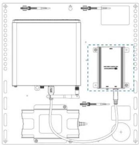
natural_image
Technical line drawing of a mechanical or electrical assembly with components and wiring (no text or symbols)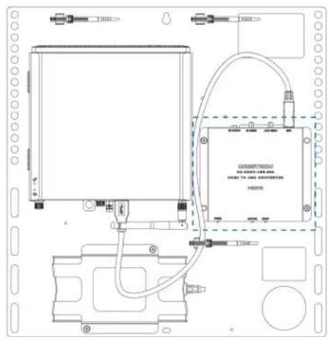
text_image
Technical schematic diagram of a device with labeled components and wiring connectionsSystem Overview
For UC Bracket Assembly with HD-CONV-USB-200
When connections are complete, the system appears as shown below. Refer to Make Connections on page 387 for detailed connection instructions.
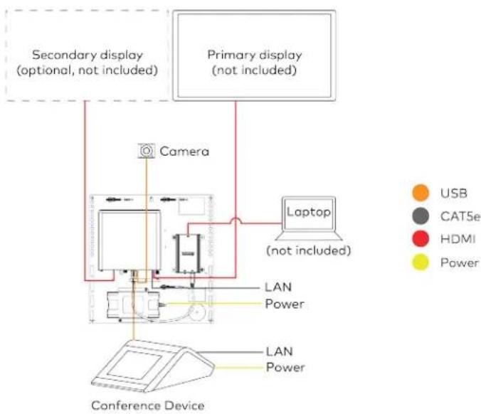
flowchart
graph TD
    A["Primary display (not included)"] --> B["Camera"]
    C["Secondary display (optional, not included)"] --> B
    D["Laptop (not included)"] --> B
    B --> E["LAN Power"]
    E --> F["Conference Device"]
    G["USB"] --> H["Computer"]
    I["CAT5e"] --> H
    J["HDMI"] --> H
    K["Power"] --> H
    style A fill:#f9f,stroke:#333
    style C fill:#f9f,stroke:#333
    style D fill:#ccf,stroke:#333
    style E fill:#cfc,stroke:#333
    style F fill:#fcc,stroke:#333
    style G fill:#ffc,stroke:#333
    style H fill:#cff,stroke:#333
    style I fill:#ffc,stroke:#333
    style J fill:#ffc,stroke:#333
    style K fill:#ffc,stroke:#333
For UC Bracket Assembly with HD-CONV-USB-300
When connections are complete, the system appears as shown below. Refer to Make Connections on page 387 for detailed connection instructions.
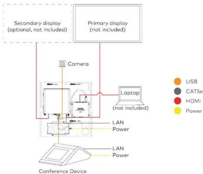
flowchart
graph TD
    A["Conference Device"] --> B["Laptop (not included)"]
    B --> C["Camera"]
    C --> D["Primary display (not included)"]
    D --> E["Secondary display (optional, not included)"]
    style A fill:#f9f,stroke:#333
    style B fill:#ccf,stroke:#333
    style C fill:#cfc,stroke:#333
    style D fill:#fcc,stroke:#333
    style E fill:#ffc,stroke:#333
Make Connections
NOTE: For reference, the UC Bracket Assembly is shown with the HD-CONV-USB-200 in the following connection diagrams. Unless otherwise indicated in this guide, the connections remain the same for the UC Bracket Assembly with HD-CONV-USB-200 and HD-CONV-USB-300.
- Make UC Engine connections as shown in the following illustration.
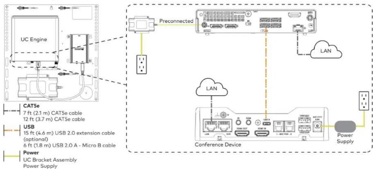
flowchart
graph TD
    A["UC Engine"] -->|Preconnected| B["Conference Device"]
    B --> C["LAN"]
    C --> D["Power Supply"]
    A --> E["Preconnected"]
    E --> F["Conference Device"]
    style A fill:#f9f,stroke:#333
    style B fill:#ccf,stroke:#333
    style C fill:#cfc,stroke:#333
    style D fill:#fcc,stroke:#333
- Connect displays to the UC Engine.
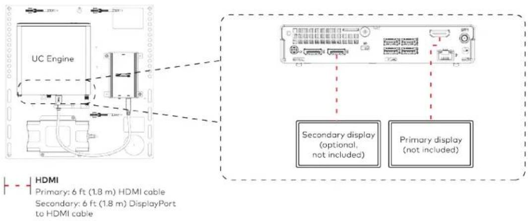
text_image
UC Engine Secondary display (optional, not included) Primary display (not included) HDMI Primary: 6 ft (1.8 m) HDMI cable Secondary: 6 ft (1.8 m) DisplayPort to HDMI cable- Connect the camera to the UC Engine as shown in the image below. Do not connect the camera to any of the other USB ports.

text_image
UC Engine Camera HD-CONV-USB-200 or HD-CONV-USB-300 (preconnected) USB 6 ft (1.8 m) USB 3.0, right angle USB-C to A- Connect a laptop to the HD-CONV-USB-200 or HD-CONV-USB-300.
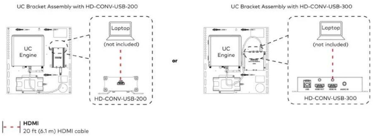
text_image
UC Bracket Assembly with HD-CONV-USB-200 Laptop (not included) or UC Bracket Assembly with HD-CONV-USB-300 Laptop (not included) HD-CONV-USB-300 HDMI 20 ft (6.1 m) HDMI cable- Bundle the cables to the bracket assembly with the integrated cable tie wraps. The cable tie wraps are reusable.
Bundle Cables
Bundle the cables together and use a provided tie wrap to secure the bundle to one of the positions on the cable retention plate at the rear of the device. Avoid bundling power and data cables together.

text_image
Bundle cables hereApply Power
Press the power button on the bottom of the UC Engine and apply power to all of the other devices in the system.
Configure the Conference Device
- On a computer, enter the IP address displayed on the conference device into a web browser.
NOTES:
• The device and computer must be on the same network switch and VLAN.
- A login with administrative rights for the device is required.
- Enter the following information in the appropriate fields:
- UC-Engine Address: Enter the IP address or hostname of the UC Engine.
NOTE: The hostname is printed on a label affixed to the UC Engine.
- UC-Engine Port: By default, port number 49500 is used. If a different port number has been configured on the UC Engine, enter that port number instead.
- UC-Engine Admin Username: Enter the username for the UC Engine. The default username is "admin".
-
UC-Engine Admin Password: Enter the login password for the UC Engine. The default password is "crestron".
-
Select Save Changes.
-
On the UC Engine, connect a USB keyboard and mouse (not included) to sign in to the Zoom Rooms service with an activation code or sign-in credentials (email and password).
NOTE: The Zoom Rooms Video mode allows sign-in only through the UC Engine. Therefore, to view the following instructions, use the conference room display connected to the UC Engine.
- Activation Code:
a. Select Enter Activation Code.
b. Enter the 16-digit activation code provided by the IT administrator managing the Zoom portal to activate the Zoom Room assigned to the activation code. The Zoom Rooms Conference Room screen is shown on the display.
- Sign In:
a. Select Sign In.
b. Enter the Zoom Room credentials and tap Sign In.
c. Select the conference room name from the list and tap Next. The Zoom Rooms Conference Room screen is shown on the display.
-
Visit the Zoom portal, navigate to Room Management > Zoom Rooms > (Room Name) > Room Settings > Rooms Profile > Devices.
-
Enable the Use Windows-attached Zoom Rooms Controller with specific Windows Monitor Hardware IDs setting. Then, copy and paste the following string into the text field: Crestron:TCT009A,Crestron:FUN0216,Crestron:FUN0270
Use Windows-attached Zoom Rooms Controller with specific Windows Monitor hardware IDs

Enable this setting only if using a Windows-attached Zoom Rooms controller device that requires a display emulator dongle or virtual display driver. Enter the manufacturer name, followed by a colon, followed by the seven character Windows monitor hardware ID shown in Windows Device Manager. Separate multiple entries with a comma. Consult your device vendor documentation for more information about using this feature.
Crestron:TCT009A,Crestron:FUN0216,Crestron:FUN0270

- On the conference device, tap Settings. If a password is required, enter the password (the default password is "1234"). The Settings screen is displayed.
-
Tap Microphone and select the conference device as the source.
-
Tap Speaker and select the conference device as the source.
- Tap Home to exit.
Configure the System
Refer to the Configuration on page 438 section to configure system features.
For detailed information on using Zoom Rooms, refer to the Zoom Rooms Help Center.
UC-MX50-Z Connections
Minimum Requirements
Ensure that the below requirements are met prior to setting up the system.
- A video display (not included) connected to the UC Engine. A second display is optional.
- A Zoom Rooms account or activation code (not included).
System Overview
When connections are complete, the system appears as shown below. Refer to Make Connections on page 392 for detailed connection instructions.

flowchart
graph TD
    A["Primary display (not included)"] --> B["Camera"]
    C["Secondary display (optional, not included)"] --> B
    D["Laptop (not included)"] --> E["Conference Device"]
    F["LAN"] --> G["LAN"]
    H["Power"] --> I["Camera"]
    J["Power"] --> K["LAN"]
    L["Power"] --> M["Conference Device"]
    N["CAT6a"] --> O["USB"]
    P["CAT5e"] --> Q["HDMI"]
    R["Power"] --> S["Power"]
Make Connections
- Make UC Engine connections as shown in the following illustration.
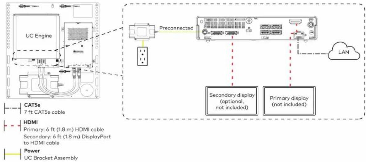
text_image
UC Engine Preconnected CAT5e 7 ft CAT5e cable HDMI Primary: 6 ft (1.8 m) HDMI cable Secondary: 6 ft (1.8 m) DisplayPort to HDMI cable Power UC Bracket Assembly Secondary display (optional, not included) Primary display (not included) LAN- Make network, content ingest, laptop, and power connections on the bottom of the conference device. Connect the conference device's power supply to an AC power outlet.
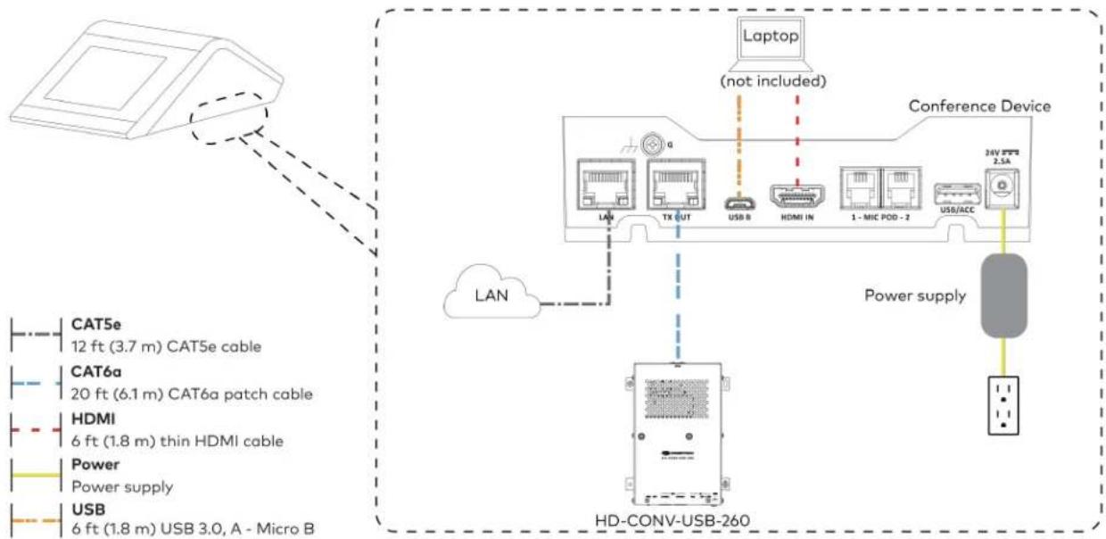
flowchart
graph TD
    A["Device"] -->|LAN| B["Conference Device"]
    B --> C["HD-CONV-USB-260"]
    C --> D["Laptop (not included)"]
    D --> E["Conference Device"]
    E --> F["Power supply"]
    F --> G["HD-CONV-USB-260"]
    style A fill:#f9f,stroke:#333
    style B fill:#ccf,stroke:#333
    style C fill:#cfc,stroke:#333
    style D fill:#fcc,stroke:#333
    style E fill:#cff,stroke:#333
    style F fill:#ffc,stroke:#333
    style G fill:#fcc,stroke:#333
- Connect the power supply and camera to the bottom of the content ingest device (HD-CONV-USB-260). Connect the power supply to an AC power outlet.

text_image
UC Engine CAMERA (USB 3.0, B) CAM (USB 3.0, A) AUX (USB 2.0, A) CONTENT (USB 3.0, B) 24V 1.25A (Barrel jack) Preconnected to UC Engine HD-CONV-USB-260 Power supply Camera Power Supply USB 6 ft (1.8 m) USB 3.0, right angle USB-C to A- Bundle the cables to the bracket assembly with the integrated cable tie wraps. The cable tie wraps are reusable.
Apply Power
Press the power button on the bottom of the UC Engine and apply power to all of the other devices in the system.
Configure the Conference Device
- On a computer, enter the IP address displayed on the conference device into a web browser.
NOTES:
• The device and computer must be on the same network switch and VLAN.
• A login with administrative rights for the device is required.
- Enter the following information in the appropriate fields:
• UC-Engine Address: Enter the IP address or hostname of the UC Engine.
NOTE: The hostname is printed on a label affixed to the UC Engine.
- UC-Engine Port: By default, port number 49500 is used. If a different port number has been configured on the UC Engine, enter that port number instead.
- UC-Engine Admin Username: Enter the username for the UC Engine. The default username is "admin".
-
UC-Engine Admin Password: Enter the login password for the UC Engine. The default password is "crestron".
-
Select Save Changes.
-
On the UC Engine, connect a USB keyboard and mouse (not included) to sign in to the Zoom Rooms service with an activation code or sign-in credentials (email and password).
NOTE: The Zoom Rooms Video mode allows sign-in only through the UC Engine. Therefore, to view the following instructions, use the conference room display connected to the UC Engine.
- Activation Code:
a. Select Enter Activation Code.
b. Enter the 16-digit activation code provided by the IT administrator managing the Zoom portal to activate the Zoom Room assigned to the activation code. The Zoom Rooms Conference Room screen is shown on the display.
- Sign In:
a. Select Sign In.
b. Enter the Zoom Room credentials and tap Sign In.
c. Select the conference room name from the list and tap Next. The Zoom Rooms Conference Room screen is shown on the display.
- Visit the Zoom portal, navigate to Room Management > Zoom Rooms > (Room Name) > Room Settings > Rooms Profile > Devices.
- Enable the Use Windows-attached Zoom Rooms Controller with specific Windows Monitor Hardware IDs setting. Then, copy and paste the following string into the text field: Crestron:TCT009A,Crestron:FUN0216,Crestron:FUN0270
Use Windows-attached Zoom Rooms Controller with specific Windows Monitor hardware IDs

Enable this setting only if using a Windows-attached Zoom Rooms controller device that requires a display emulator dongle or virtual display driver. Enter the manufacturer name, followed by a colon, followed by the seven character Windows monitor hardware ID shown in Windows Device Manager. Separate multiple entries with a comma. Consult your device vendor documentation for more information about using this feature.
Crestron:TCT009A,Crestron:FUN0216,Crestron:FUN0270

- On the conference device, tap Settings. If a password is required, enter the password (the default password is "1234"). The Settings screen is displayed.
- Tap Microphone and select the conference device as the source.
- Tap Speaker and select the conference device as the source.
- Tap Home to exit.
Configure the System
Refer to the Configuration on page 438 section to configure system features.
For detailed information on using Zoom Rooms, refer to the Zoom Rooms Help Center.
UC-M50-Z-UPGRD Connections
Minimum Requirements
Ensure that the below requirements are met prior to setting up the system.
- A Crestron Flex tabletop conference device and camera.
- A video display (not included) connected to the UC Engine. A second display is optional.
- A Zoom Rooms account or activation code (not included).
Configure the Conference Device
Prior to making system connections, deployed conference devices must be configured to operate as part of a complete Zoom Rooms system. Some deployed conference devices may be operating in Crestron Default mode.
To configure the conference device to operate in Zoom Rooms Video mode:
- On a computer, enter the IP address displayed on the conference device into a web browser.
NOTES:
- The device and computer must be on the same network switch and VLAN.
-
A login with administrative rights for the device is required.
-
Log in to the device and navigate to DEVICE > Applications.
- From the Application Mode drop down menu, select Zoom Rooms Video.
- Select Save Changes. The conference device will reboot in Zoom Rooms Video mode and log out all users.
Identify the UC Bracket Assembly
The UC Bracket Assembly is available in two models. Identify the model included with your Crestron Flex system. Tap or click the corresponding image below to navigate to the appropriate connection instructions.
UC Bracket Assembly with HD-CONV-USB-200 UC Bracket Assembly with HD-CONV-USB-300

natural_image
Technical line drawing of a mechanical or electrical assembly with no visible text, numbers, or symbols.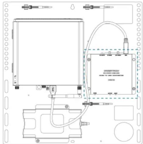
text_image
DRESSROOM HOME TO JAS DESIGNERS HORNSystem Overview
For UC Bracket Assembly with HD-CONV-USB-200
When connections are complete, the system appears as shown below. Refer to Make Connections on page 398 for detailed connection instructions.
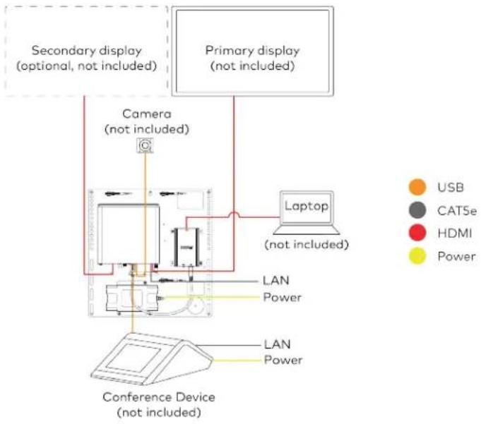
flowchart
graph TD
    A["Primary display (not included)"] --> B["Laptop (not included)"]
    C["Secondary display (optional, not included)"] --> D["Camera (not included)"]
    E["Conference Device (not included)"] --> F["LAN Power"]
    G["Computer"] --> H["Camera (not included)"]
    I["Lab Laptop"] --> J["Power"]
    K["USB"] --> L["Power"]
    M["CAT5e"] --> N["Power"]
For UC Bracket Assembly with HD-CONV-USB-300
When connections are complete, the system appears as shown below. Refer to Make Connections on page 398 for detailed connection instructions.
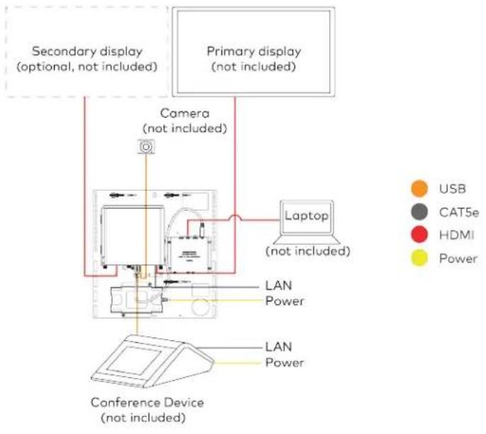
flowchart
graph TD
    A["Primary display (not included)"] --> B["Laptop (not included)"]
    C["Secondary display (optional, not included)"] --> D["Camera (not included)"]
    E["Conference Device (not included)"] --> F["LAN Power"]
    G["Computer"] --> H["Camera (not included)"]
    I["USB"] --> J["Computer"]
    K["CAT5e"] --> L["Computer"]
    M["HDMI"] --> N["Computer"]
    O["Power"] --> P["Computer"]
NOTE: For reference, the UC Bracket Assembly is shown with the HD-CONV-USB-200 in the following connection diagrams. Unless otherwise indicated in this guide, the connections remain the same for the UC Bracket Assembly with HD-CONV-USB-200 and HD-CONV-USB-300.
- Make UC Engine connections as shown in the following illustration.
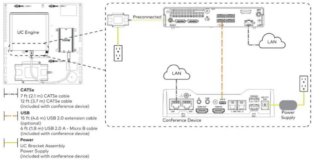
flowchart
graph TD
    A["UC Engine"] --> B["Preconnected"]
    B --> C["Conference Device"]
    C --> D["Power Supply"]
    subgraph CAT5e
        E["7 ft (2.1 m) CAT5e cable"]
        F["12 ft (3.7 m) CAT5e cable (included with conference device)"]
    end
    subgraph USB
        G["15 ft (4.6 m) USB 2.0 extension cable (optional)"]
        H["6 ft (1.8 m) USB 2.0 A - Micro B cable (included with conference device)"]
    end
    subgraph Power
        I["UC Bracket Assembly"]
        J["Power Supply (included with conference device)"]
    end
    B --> K["LAN"]
    C --> L["LAN"]
    C --> M["Power Supply"]
    style A fill:#f9f,stroke:#333
    style B fill:#ccf,stroke:#333
    style C fill:#cfc,stroke:#333
    style D fill:#fcc,stroke:#333
    style E fill:#ffc,stroke:#333
    style F fill:#ffc,stroke:#333
    style G fill:#ffc,stroke:#333
    style H fill:#ffc,stroke:#333
    style I fill:#ffc,stroke:#333
    style J fill:#ffc,stroke:#333
    style K fill:#fff,stroke:#333
    style L fill:#fff,stroke:#333
    style M fill:#fff,stroke:#333
- Connect displays to the UC Engine.

text_image
UC Engine Secondary display (optional, not included) Primary display (not included) HDMI Primary: 6 ft (1.8 m) HDMI cable Secondary: 6 ft (1.8 m) DisplayPort to HDMI cable- Connect a camera (not included) to the UC Engine as shown in the image below. Do not connect the camera to any of the other USB ports.
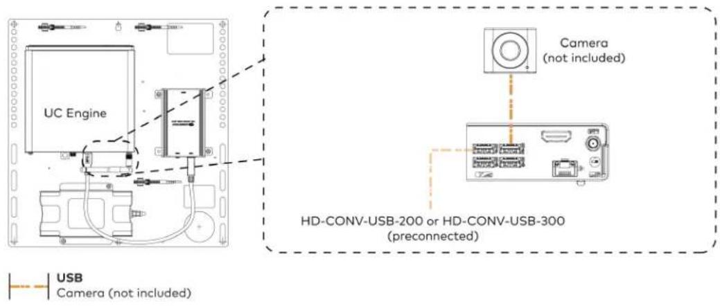
text_image
UC Engine Camera (not included) HD-CONV-USB-200 or HD-CONV-USB-300 (preconnected) USB Camera (not included)- Connect a laptop to the HD-CONV-USB-200 or HD-CONV-USB-300.

text_image
UC Bracket Assembly with HD-CONV-USB-200 Laptop (not included) or UC Bracket Assembly with HD-CONV-USB-300 Laptop (not included) HD-CONV-USB-300 HDMI 20 ft (6.1 m) HDMI cable- Bundle the cables to the bracket assembly with the integrated cable tie wraps. The cable tie wraps are reusable.
Bundle Cables
Bundle the cables together and use a provided tie wrap to secure the bundle to one of the positions on the cable retention plate at the rear of the device. Avoid bundling power and data cables together.
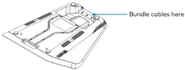
text_image
Bundle cables hereApply Power
Press the power button on the bottom of the UC Engine and apply power to all of the other devices in the system.
Complete the Conference Device Configuration
- On a computer, enter the IP address displayed on the conference device into a web browser.
NOTES:
- The device and computer must be on the same network switch and VLAN.
-
A login with administrative rights for the device is required.
-
Enter the following information in the appropriate fields:
- UC-Engine Address: Enter the IP address or hostname of the UC Engine.
NOTE: The hostname is printed on a label affixed to the UC Engine.
- UC-Engine Port: By default, port number 49500 is used. If a different port number has been configured on the UC Engine, enter that port number instead.
- UC-Engine Admin Username: Enter the username for the UC Engine. The default username is "admin".
-
UC-Engine Admin Password: Enter the login password for the UC Engine. The default password is "crestron".
-
Select Save Changes.
- On the UC Engine, connect a USB keyboard and mouse (not included) to sign in to the Zoom Rooms service with an activation code or sign-in credentials (email and password).
NOTE: The Zoom Rooms Video mode allows sign-in only through the UC Engine. Therefore, to view the following instructions, use the conference room display connected to the UC Engine.
- Activation Code:
a. Select Enter Activation Code.
b. Enter the 16-digit activation code provided by the IT administrator managing the Zoom portal to activate the Zoom Room assigned to the activation code. The Zoom Rooms Conference Room screen is shown on the display.
- Sign In:
a. Select Sign In.
b. Enter the Zoom Room credentials and tap Sign In.
c. Select the conference room name from the list and tap Next. The Zoom Rooms Conference Room screen is shown on the display.
-
Visit the Zoom portal, navigate to Room Management > Zoom Rooms > (Room Name) > Room Settings > Rooms Profile > Devices.
-
Enable the Use Windows-attached Zoom Rooms Controller with specific Windows Monitor Hardware IDs setting. Then, copy and paste the following string into the text field: Crestron:TCT009A,Crestron:FUN0216,Crestron:FUN0270
Use Windows-attached Zoom Rooms Controller with specific Windows Monitor hardware IDs

Enable this setting only if using a Windows-attached Zoom Rooms controller device that requires a display emulator dongle or virtual display driver. Enter the manufacturer name, followed by a colon, followed by the seven character Windows monitor hardware ID shown in Windows Device Manager. Separate multiple entries with a comma. Consult your device vendor documentation for more information about using this feature.
Crestron:TCT009A,Crestron:FUN0216,Crestron:FUN0270

-
On the conference device, tap Settings. If a password is required, enter the password (the default password is "1234"). The Settings screen is displayed.
-
Tap Microphone and select the conference device as the source.
-
Tap Speaker and select the conference device as the source.
-
Tap Home to exit.
Configure the System
Refer to the Configuration on page 438 section to configure system features.
For detailed information on using Zoom Rooms, refer to the Zoom Rooms Help Center.
UC-MX50-Z-UPGRD Connections
Minimum Requirements
Ensure that the below requirements are met prior to setting up the system.
• A Crestron Flex tabletop conference device and camera.
- A video display (not included) connected to the UC Engine. A second display is optional.
- A Zoom Rooms account or activation code (not included).
Configure the Conference Device
Prior to making system connections, deployed conference devices must be configured to operate as part of a complete Zoom Rooms system. Some deployed conference devices may be operating in Crestron Default mode.
To configure the conference device to operate in Zoom Rooms Video mode:
- On a computer, enter the IP address displayed on the conference device into a web browser.
NOTES:
- The device and computer must be on the same network switch and VLAN.
-
A login with administrative rights for the device is required.
-
Log in to the device and navigate to DEVICE > Applications.
- From the Application Mode drop down menu, select Zoom Rooms Video.
- Select Save Changes. The conference device will reboot in Zoom Rooms Video mode and log out all users.
System Overview
When connections are complete, the system appears as shown below. Refer to Make Connections on page 403 for detailed connection instructions.
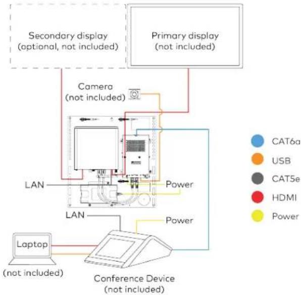
flowchart
graph TD
    A["Primary display (not included)"] --> B["Secondary display (optional, not included)"]
    B --> C["Camera (not included)"]
    C --> D["Laptop (not included)"]
    D --> E["Conference Device (not included)"]
    E --> F["LAN"]
    F --> G["Power"]
    G --> H["LAN"]
    H --> I["Power"]
    I --> J["Water Supply"]
    style A fill:#f9f,stroke:#333
    style B fill:#ccf,stroke:#333
    style C fill:#cfc,stroke:#333
    style D fill:#fcc,stroke:#333
    style E fill:#cff,stroke:#333
    style F fill:#ffc,stroke:#333
    style G fill:#fcc,stroke:#333
    style H fill:#ffc,stroke:#333
    style I fill:#fcc,stroke:#333
    style J fill:#ffc,stroke:#333
Make Connections
- Make UC Engine connections as shown in the following illustration.

flowchart
graph TD
    A["UC Engine"] -->|Preconnected| B["Preconnected"]
    B --> C["Secondary display (optional, not included)"]
    B --> D["Primary display (not included)"]
    E["CATSe 7 ft CATSe cable"] --> A
    F["HDMI Primary: 6 ft (1.8 m) HDMI cable (included with conference device)"]
    G["Secondary: 6 ft (1.8 m) DisplayPort to HDMI cable"] --> F
    H["Power UC Bracket Assembly"] --> I["Power"]
    style A fill:#f9f,stroke:#333
    style B fill:#ccf,stroke:#333
    style C fill:#cfc,stroke:#333
    style D fill:#fcc,stroke:#333
    style E fill:#ffc,stroke:#333
    style F fill:#cfc,stroke:#333
    style G fill:#cfc,stroke:#333
    style H fill:#cfc,stroke:#333
- Connect the power supply and camera to the bottom of the content ingest device (HD-CONV-USB-260). Connect the power supply to an AC power outlet.

text_image
UC Engine CAMERA (USB 3.0, B) CAM (USB 3.0, A) AUX (USB 2.0, A) CONTENT (USB 3.0, B) 24V 1.25A (Barrel jack) Preconnected to UC Engine HD-CONV-USB-260 Power supply USB 6 ft (1.8 m) USB 3.0, right angle USB-C to A (included with conference device) Camera (not included)- Make network, content ingest, laptop, and power connections on the bottom of the conference device. Connect the conference device's power supply to an AC power outlet.
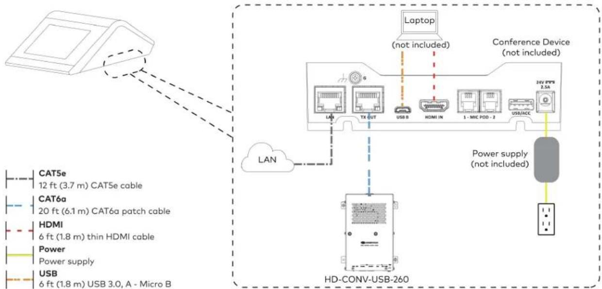
flowchart
graph TD
    A["Camera"] --> B["LAN"]
    B --> C["HD-CONV-USB-260"]
    C --> D["Laptop (not included)"]
    D --> E["Conference Device (not included)"]
    E --> F["24V PFS 2.5A"]
    C --> G["Power supply (not included)"]
    G --> H["HD-CONV-USB-260"]
    style A fill:#f9f,stroke:#333
    style B fill:#ccf,stroke:#333
    style C fill:#cfc,stroke:#333
    style D fill:#fcc,stroke:#333
    style E fill:#cff,stroke:#333
    style F fill:#ffc,stroke:#333
    style G fill:#fcc,stroke:#333
    style H fill:#ffc,stroke:#333
(All cables are included with the conference device)
- Bundle the cables to the bracket assembly with the integrated cable tie wraps. The cable tie wraps are reusable.
Bundle Cables
Bundle the cables together and use a provided tie wrap to secure the bundle to one of the positions on the cable retention plate at the rear of the device. Avoid bundling power and data cables together.
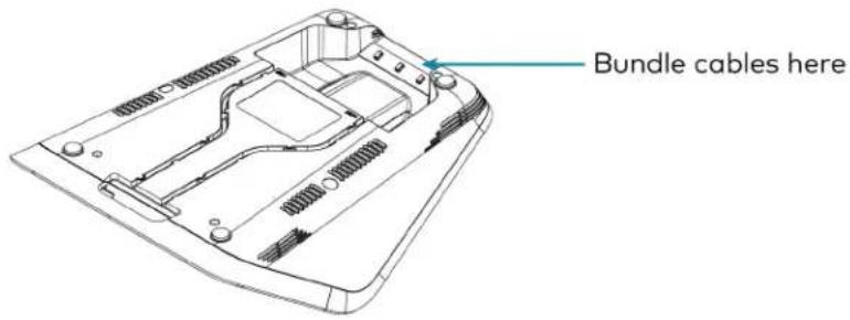
text_image
Bundle cables hereApply Power
Press the power button on the bottom of the UC Engine and apply power to all of the other devices in the system.
- On a computer, enter the IP address displayed on the conference device into a web browser.
NOTES:
- The device and computer must be on the same network switch and VLAN.
-
A login with administrative rights for the device is required.
-
Enter the following information in the appropriate fields:
- UC-Engine Address: Enter the IP address or hostname of the UC Engine.
NOTE: The hostname is printed on a label affixed to the UC Engine.
- UC-Engine Port: By default, port number 49500 is used. If a different port number has been configured on the UC Engine, enter that port number instead.
- UC-Engine Admin Username: Enter the username for the UC Engine. The default username is "admin".
-
UC-Engine Admin Password: Enter the login password for the UC Engine. The default password is "crestron".
-
Select Save Changes.
- On the UC Engine, connect a USB keyboard and mouse (not included) to sign in to the Zoom Rooms service with an activation code or sign-in credentials (email and password).
NOTE: The Zoom Rooms Video mode allows sign-in only through the UC Engine. Therefore, to view the following instructions, use the conference room display connected to the UC Engine.
- Activation Code:
a. Select Enter Activation Code.
b. Enter the 16-digit activation code provided by the IT administrator managing the Zoom portal to activate the Zoom Room assigned to the activation code. The Zoom Rooms Conference Room screen is shown on the display.
- Sign In:
a. Select Sign In.
b. Enter the Zoom Room credentials and tap Sign In.
c. Select the conference room name from the list and tap Next. The Zoom Rooms Conference Room screen is shown on the display.
-
Visit the Zoom portal, navigate to Room Management > Zoom Rooms > (Room Name) > Room Settings > Rooms Profile > Devices.
-
Enable the Use Windows-attached Zoom Rooms Controller with specific Windows Monitor Hardware IDs setting. Then, copy and paste the following string into the text field: Crestron:TCT009A,Crestron:FUN0216,Crestron:FUN0270
Use Windows-attached Zoom Rooms Controller with specific Windows Monitor hardware IDs

Enable this setting only if using a Windows-attached Zoom Rooms controller device that requires a display emulator dongle or virtual display driver. Enter the manufacturer name, followed by a colon, followed by the seven character Windows monitor hardware ID shown in Windows Device Manager. Separate multiple entries with a comma. Consult your device vendor documentation for more information about using this feature.
Crestron:TCT009A,Crestron:FUN0216,Crestron:FUN0270

-
On the conference device, tap Settings. If a password is required, enter the password (the default password is "1234"). The Settings screen is displayed.
-
Tap Microphone and select the conference device as the source.
-
Tap Speaker and select the conference device as the source.
-
Tap Home to exit.
Configure the System
Refer to the Configuration on page 438 section to configure system features.
For detailed information on using Zoom Rooms, refer to the Zoom Rooms Help Center.
UC-M70-Z Connections
Minimum Requirements
Ensure that the below requirements are met prior to setting up the system.
- A video display (not included) connected to the UC Engine. A second display is optional.
- A Zoom Rooms account or activation code (not included).
Install the Cable Retention Plate
The included cable retention plate provides tie-down points for cables that connect to the Crestron® conference device.
Remove the adhesive backing from the cable retention plate and install the plate on the underside of the conference device as shown in the following diagram. Ensure the cable retention plate is firmly attached before securing cables.
CAUTION: When turning over the device, place the device on a soft surface to avoid damage.
NOTE: If a swivel mount kit (CCS-UCA-SMK) is to be used, use the cable retention bracket included with the swivel mount kit as described in the CCS-UCA-SMK DO Guide (Doc. 7882).

text_image
Install cable retention plate here Cable retention plate installedIdentify the UC Bracket Assembly
The UC Bracket Assembly is available in two models. Identify the model included with your Crestron Flex system. Tap or click the corresponding image below to navigate to the appropriate connection instructions.
UC Bracket Assembly with HD-CONV-USB-200 UC Bracket Assembly with HD-CONV-USB-300

natural_image
Technical line drawing of an electronic device with ports, cables, and a central control panel (no text or symbols)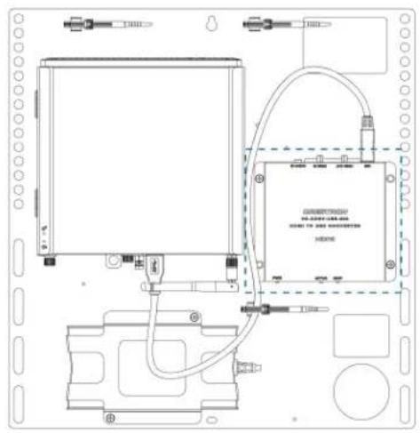
text_image
Technical schematic diagram of a device with labeled components and wiring connectionsSystem Overview
For UC Bracket Assembly with HD-CONV-USB-200
When connections are complete, the system appears as shown below. Refer to Make Connections on page 410 for detailed connection instructions.
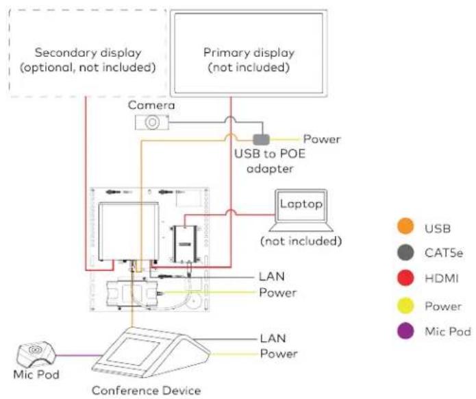
flowchart
graph TD
    A["Primary display (not included)"] --> B["Camera"]
    B --> C["USB to POE adapter"]
    C --> D["Laptop (not included)"]
    D --> E["LAN Power"]
    E --> F["Conference Device"]
    G["Secondary display (optional, not included)"] --> H["Camera"]
    I["Mic Pod"] --> J["Conference Device"]
    K["Power"] --> L["USB to POE adapter"]
    M["Power"] --> N["Laptop (not included)"]
    O["Power"] --> P["LAN Power"]
    Q["Power"] --> R["LAN Power"]
For UC Bracket Assembly with HD-CONV-USB-300
When connections are complete, the system appears as shown below. Refer to Make Connections on page 410 for detailed connection instructions.

flowchart
graph TD
    A["Primary display (not included)"] --> B["Camera"]
    B --> C["USB to POE adapter"]
    C --> D["Laptop (not included)"]
    D --> E["LAN Power"]
    E --> F["Conference Device"]
    G["Secondary display (optional, not included)"] --> H["Camera"]
    I["Mic Pod"] --> J["Conference Device"]
    style A fill:#f9f,stroke:#333
    style B fill:#ccf,stroke:#333
    style C fill:#cfc,stroke:#333
    style D fill:#fcc,stroke:#333
    style E fill:#cff,stroke:#333
    style F fill:#ffc,stroke:#333
    style G fill:#cfc,stroke:#333
    style H fill:#fcc,stroke:#333
Make Connections
NOTE: For reference, the UC Bracket Assembly is shown with the HD-CONV-USB-200 in the following connection diagrams. Unless otherwise indicated in this guide, the connections remain the same for the UC Bracket Assembly with HD-CONV-USB-200 and HD-CONV-USB-300.
- Make UC Engine connections as shown in the following illustration.
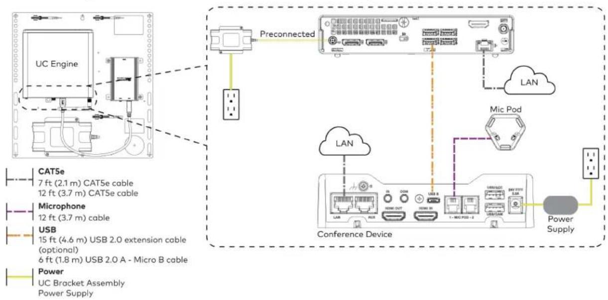
flowchart
graph TD
    A["UC Engine"] -->|Preconnected| B["Conference Device"]
    B --> C["LAN"]
    B --> D["Mic Pod"]
    B --> E["Power Supply"]
    F["CAT5e 7 ft (2.1 m) CAT5e cable 12 ft (3.7 m) CAT5e cable"] --> A
    G["Microphone 12 ft (3.7 m) cable"] --> A
    H["USB 15 ft (4.6 m) USB 2.0 extension cable (optional) 6 ft (1.8 m) USB 2.0 A - Micro B cable"] --> A
    I["Power UC Bracket Assembly Power Supply"] --> A
- Connect displays to the UC Engine.
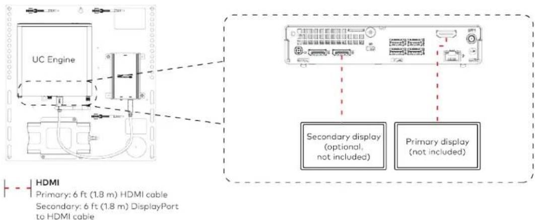
text_image
UC Engine HDMI Primary: 6 ft (1.8 m) HDMI cable Secondary: 6 ft (1.8 m) DisplayPort to HDMI cable Secondary display (optional, not included) Primary display (not included)- Connect the camera to the UC Engine as shown in the image below. Do not connect the camera to any of the other USB ports.
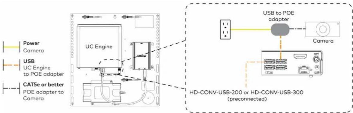
text_image
Power Camera USB UC Engine to POE adapter CAT5e or better POE adapter to Camera UC Engine USB to POE adapter Camera HD-CONV-USB-200 or HD-CONV-USB-300 (preconnected)- Connect a laptop to the HD-CONV-USB-200 or HD-CONV-USB-300.

text_image
UC Bracket Assembly with HD-CONV-USB-200 Laptop (not included) HD-CONV-USB-200 or UC Bracket Assembly with HD-CONV-USB-300 Laptop (not included) HD-CONV-USB-300 HDMI 20 ft (6.1 m) HDMI cable- Bundle the cables to the bracket assembly with the integrated cable tie wraps. The cable tie wraps are reusable.
Bundle Cables
Bundle the cables together and use a provided tie wrap to secure the bundle to one of the positions on the cable retention plate at the rear of the device. Avoid bundling power and data cables together.

text_image
Bundle cables hereApply Power
Press the power button on the bottom of the UC Engine and apply power to all of the other devices in the system.
Configure the Conference Device
- On a computer, enter the IP address displayed on the conference device into a web browser.
NOTES:
• The device and computer must be on the same network switch and VLAN.
- A login with administrative rights for the device is required.
- Enter the following information in the appropriate fields:
- UC-Engine Address: Enter the IP address or hostname of the UC Engine.
NOTE: The hostname is printed on a label affixed to the UC Engine.
- UC-Engine Port: By default, port number 49500 is used. If a different port number has been configured on the UC Engine, enter that port number instead.
- UC-Engine Admin Username: Enter the username for the UC Engine. The default username is "admin".
-
UC-Engine Admin Password: Enter the login password for the UC Engine. The default password is "crestron".
-
Select Save Changes.
-
On the UC Engine, connect a USB keyboard and mouse (not included) to sign in to the Zoom Rooms service with an activation code or sign-in credentials (email and password).
NOTE: The Zoom Rooms Video mode allows sign-in only through the UC Engine. Therefore, to view the following instructions, use the conference room display connected to the UC Engine.
- Activation Code:
a. Select Enter Activation Code.
b. Enter the 16-digit activation code provided by the IT administrator managing the Zoom portal to activate the Zoom Room assigned to the activation code. The Zoom Rooms Conference Room screen is shown on the display.
- Sign In:
a. Select Sign In.
b. Enter the Zoom Room credentials and tap Sign In.
c. Select the conference room name from the list and tap Next. The Zoom Rooms Conference Room screen is shown on the display.
-
Visit the Zoom portal, navigate to Room Management > Zoom Rooms > (Room Name) > Room Settings > Rooms Profile > Devices.
-
Enable the Use Windows-attached Zoom Rooms Controller with specific Windows Monitor Hardware IDs setting. Then, copy and paste the following string into the text field: Crestron:TCT009A,Crestron:FUN0216,Crestron:FUN0270
Use Windows-attached Zoom Rooms Controller with specific Windows Monitor hardware IDs

Enable this setting only if using a Windows-attached Zoom Rooms controller device that requires a display emulator dongle or virtual display driver. Enter the manufacturer name, followed by a colon, followed by the seven character Windows monitor hardware ID shown in Windows Device Manager. Separate multiple entries with a comma. Consult your device vendor documentation for more information about using this feature.
Crestron:TCT009A,Crestron:FUN0216,Crestron:FUN0270

- On the conference device, tap Settings. If a password is required, enter the password (the default password is "1234"). The Settings screen is displayed.
-
Tap Microphone and select the conference device as the source.
-
Tap Speaker and select the conference device as the source.
- Tap Home to exit.
Configure the System
Refer to the Configuration on page 438 section to configure system features.
For detailed information on using Zoom Rooms, refer to the Zoom Rooms Help Center.
UC-MX70-Z Connections
Minimum Requirements
Ensure that the below requirements are met prior to setting up the system.
- A video display (not included) connected to the UC Engine. A second display is optional.
- A Zoom Rooms account or activation code (not included).
System Overview
When connections are complete, the system appears as shown below. Refer to Make Connections on page 415 for detailed connection instructions.
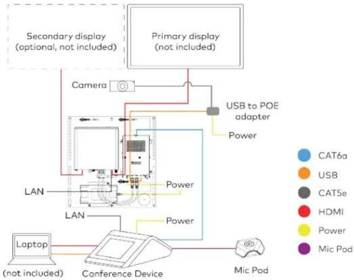
flowchart
graph TD
    A["Primary display (not included)"] --> B["Camera"]
    B --> C["USB to POE adapter"]
    C --> D["Power"]
    D --> E["LAN"]
    E --> F["Laptop (not included)"]
    F --> G["Conference Device"]
    G --> H["Mic Pod"]
    I["Secondary display (optional, not included)"] --> J["Camera"]
    K["Primary display (not included)"] --> L["USB to POE adapter"]
    M["Conference Device"] --> N["Power"]
    O["Conference Device"] --> P["Power"]
Make Connections
- Make UC Engine connections as shown in the following illustration.
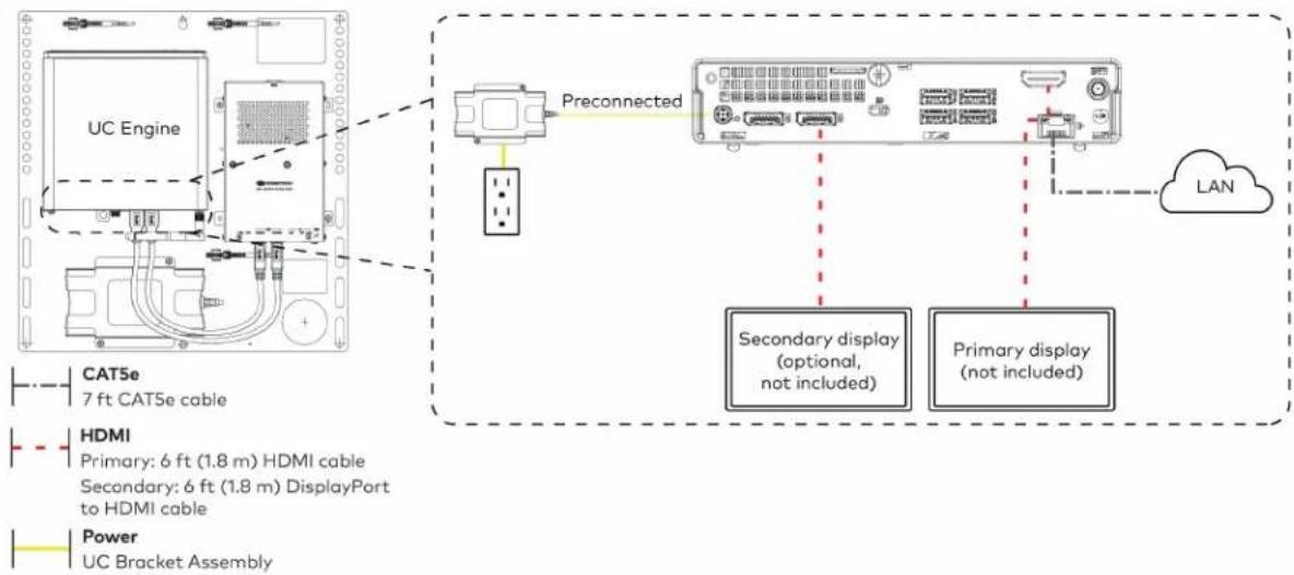
flowchart
graph TD
    A["UC Engine"] -->|Preconnected| B["LAN"]
    C["CAT5e 7 ft CAT5e cable"] --> A
    D["HDMI Primary: 6 ft (1.8 m) HDMI cable"] --> A
    E["Secondary: 6 ft (1.8 m) DisplayPort to HDMI cable"] --> A
    F["Power UC Bracket Assembly"] --> A
    B --> G["Secondary display (optional, not included)"]
    B --> H["Primary display (not included)"]
- Make network, content ingest, laptop, and power connections on the bottom of the conference device. Connect the conference device's power supply to an AC power outlet.
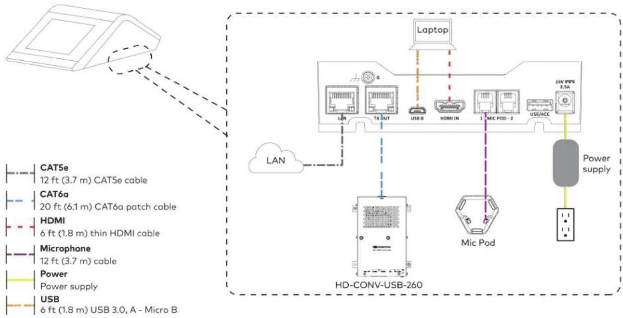
flowchart
graph TD
    A["Device"] -->|Dashed arrow| B["Laptop"]
    B --> C["HD-CONV-USB-260"]
    C --> D["MC Pod"]
    D --> E["24V PFS 2.5A"]
    C --> F["LAN"]
    F --> G["LED System"]
    G --> H["USB"]
    H --> I["Power Supply"]
    style A fill:#f9f,stroke:#333
    style B fill:#ccf,stroke:#333
    style C fill:#cfc,stroke:#333
    style D fill:#fcc,stroke:#333
    style E fill:#cff,stroke:#333
    style F fill:#ffc,stroke:#333
    style G fill:#fcf,stroke:#333
    style H fill:#cff,stroke:#333
    style I fill:#ffc,stroke:#333
- Connect the power supply and camera to the bottom of the content ingest device (HD-CONV-USB-260). Connect the power supplies to an AC power outlet.

text_image
UC Engine CAT5e or better POE adapter to Camera CAMERA (USB 3.0, B) CAM (USB 3.0, A) AUX (USB 2.0, A) CONTENT (USB 3.0, B) 24V 1.25A (Barrel jack) Preconnected to UC Engine HD-CONV-USB-260 Power supply USB to POE adapter Camera USB to POE adapter Power Power supply Camera USB to POE adapter- Bundle the cables to the bracket assembly with the integrated cable tie wraps. The cable tie wraps are reusable.
Apply Power
Press the power button on the bottom of the UC Engine and apply power to all of the other devices in the system.
Configure the Conference Device
- On a computer, enter the IP address displayed on the conference device into a web browser.
NOTES:
-
The device and computer must be on the same network switch and VLAN.
• A login with administrative rights for the device is required. -
Enter the following information in the appropriate fields:
- UC-Engine Address: Enter the IP address or hostname of the UC Engine.
NOTE: The hostname is printed on a label affixed to the UC Engine.
- UC-Engine Port: By default, port number 49500 is used. If a different port number has been configured on the UC Engine, enter that port number instead.
- UC-Engine Admin Username: Enter the username for the UC Engine. The default username is "admin".
-
UC-Engine Admin Password: Enter the login password for the UC Engine. The default password is "crestron".
-
Select Save Changes.
-
On the UC Engine, connect a USB keyboard and mouse (not included) to sign in to the Zoom Rooms service with an activation code or sign-in credentials (email and password).
NOTE: The Zoom Rooms Video mode allows sign-in only through the UC Engine. Therefore, to view the following instructions, use the conference room display connected to the UC Engine.
- Activation Code:
a. Select Enter Activation Code.
b. Enter the 16-digit activation code provided by the IT administrator managing the Zoom portal to activate the Zoom Room assigned to the activation code. The Zoom Rooms Conference Room screen is shown on the display.
- Sign In:
a. Select Sign In.
b. Enter the Zoom Room credentials and tap Sign In.
c. Select the conference room name from the list and tap Next. The Zoom Rooms Conference Room screen is shown on the display.
- Visit the Zoom portal, navigate to Room Management > Zoom Rooms > (Room Name) > Room Settings > Rooms Profile > Devices.
- Enable the Use Windows-attached Zoom Rooms Controller with specific Windows Monitor Hardware IDs setting. Then, copy and paste the following string into the text field: Crestron:TCT009A,Crestron:FUN0216,Crestron:FUN0270
Use Windows-attached Zoom Rooms Controller with specific Windows Monitor hardware IDs

Enable this setting only if using a Windows-attached Zoom Rooms controller device that requires a display emulator dongle or virtual display driver. Enter the manufacturer name, followed by a colon, followed by the seven character Windows monitor hardware ID shown in Windows Device Manager. Separate multiple entries with a comma. Consult your device vendor documentation for more information about using this feature.
Crestron:TCT009A,Crestron:FUN0216,Crestron:FUN0270

- On the conference device, tap Settings. If a password is required, enter the password (the default password is "1234"). The Settings screen is displayed.
- Tap Microphone and select the conference device as the source.
- Tap Speaker and select the conference device as the source.
- Tap Home to exit.
Configure the System
Refer to the Configuration on page 438 section to configure system features.
For detailed information on using Zoom Rooms, refer to the Zoom Rooms Help Center.
UC-M70-NC-Z Connections
Minimum Requirements
Ensure that the below requirements are met prior to setting up the system.
• A certified USB Camera (not included).
- A video display (not included) connected to the UC Engine. A second display is optional.
- A Zoom Rooms account or activation code (not included).
Install the Cable Retention Plate
The included cable retention plate provides tie-down points for cables that connect to the Crestron® conference device.
Remove the adhesive backing from the cable retention plate and install the plate on the underside of the conference device as shown in the following diagram. Ensure the cable retention plate is firmly attached before securing cables.
CAUTION: When turning over the device, place the device on a soft surface to avoid damage.
NOTE: If a swivel mount kit (CCS-UCA-SMK) is to be used, use the cable retention bracket included with the swivel mount kit as described in the CCS-UCA-SMK DO Guide (Doc. 7882).

text_image
Install cable retention plate here Cable retention plate installedIdentify the UC Bracket Assembly
The UC Bracket Assembly is available in two models. Identify the model included with your Crestron Flex system. Tap or click the corresponding image below to navigate to the appropriate connection instructions.
UC Bracket Assembly with HD-CONV-USB-200 UC Bracket Assembly with HD-CONV-USB-300
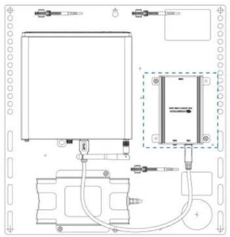
natural_image
Technical line drawing of an electronic device with ports, cables, and a central control panel (no text or symbols)
text_image
Technical schematic diagram of a device with labeled components and wiring connectionsSystem Overview
For UC Bracket Assembly with HD-CONV-USB-200
When connections are complete, the system appears as shown below. Refer to Make Connections on page 421 for detailed connection instructions.
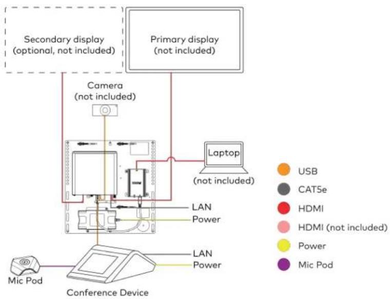
flowchart
graph TD
    A["Conference Device"] --> B["Laptop (not included)"]
    B --> C["Camera (not included)"]
    C --> D["Primary display (not included)"]
    D --> E["Secondary display (optional, not included)"]
    F["Mic Pod"] --> G["Conference Device"]
    H["USB"] --> I["Computer"]
    J["CATSe"] --> K["Computer"]
    L["HDMI"] --> M["Computer"]
    N["HDMI (not included)"] --> O["Computer"]
    P["Power"] --> Q["Computer"]
    R["Mic Pod"] --> S["Computer"]
For UC Bracket Assembly with HD-CONV-USB-300
When connections are complete, the system appears as shown below. Refer to Make Connections on page 421 for detailed connection instructions.

flowchart
graph TD
    A["Conference Device"] --> B["Laptop (not included)"]
    B --> C["Camera (not included)"]
    C --> D["Primary display (not included)"]
    D --> E["Secondary display (optional, not included)"]
    F["Mic Pod"] --> G["Conference Device"]
    H["USB"] --> I["Computer"]
    J["CAT5e"] --> K["Computer"]
    L["HDMI"] --> M["Computer"]
    N["HDMI (not included)"] --> O["Computer"]
    P["Power"] --> Q["Computer"]
    R["Mic Pod"] --> S["Computer"]
Make Connections
NOTE: For reference, the UC Bracket Assembly is shown with the HD-CONV-USB-200 in the following connection diagrams. Unless otherwise indicated in this guide, the connections remain the same for the UC Bracket Assembly with HD-CONV-USB-200 and HD-CONV-USB-300.
- Make UC Engine connections as shown in the following illustration.

flowchart
graph TD
    A["UC Engine"] -->|Preconnected| B["Conference Device"]
    B --> C["Micro Pod"]
    C --> D["LAN"]
    D --> E["Power Supply"]
    A --> F["CAT5e 7 ft (2.1 m) CAT5e cable 12 ft (3.7 m) CAT5e cable"]
    A --> G["Microphone 12 ft (3.7 m) cable"]
    A --> H["USB 15 ft (4.6 m) USB 2.0 extension cable (optional) 6 ft (1.8 m) USB 2.0 A - Micro B cable"]
    A --> I["Power UC Bracket Assembly Power Supply"]
- Connect displays to the UC Engine.

text_image
UC Engine Secondary display (optional, not included) Primary display (not included) HDMI Primary: 6 ft (1.8 m) HDMI cable Secondary: 6 ft (1.8 m) DisplayPort to HDMI cable- Connect the camera to the UC Engine as shown in the image below. Do not connect the camera to any of the other USB ports.
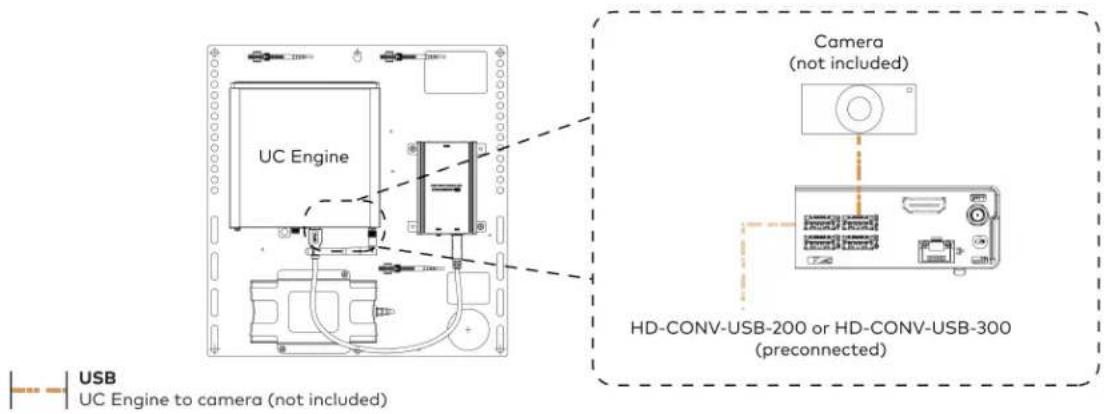
text_image
UC Engine Camera (not included) HD-CONV-USB-200 or HD-CONV-USB-300 (preconnected) USB UC Engine to camera (not included)- Connect a laptop to the HD-CONV-USB-200 or HD-CONV-USB-300.

text_image
UC Bracket Assembly with HD-CONV-USB-200 Laptop (not included) HD-CONV-USB-200 or UC Bracket Assembly with HD-CONV-USB-300 Laptop (not included) HD-CONV-USB-300 HDMI 20 ft (6.1 m) HDMI cable- Bundle the cables to the bracket assembly with the integrated cable tie wraps. The cable tie wraps are reusable.
Bundle Cables
Bundle the cables together and use a provided tie wrap to secure the bundle to one of the positions on the cable retention plate at the rear of the device. Avoid bundling power and data cables together.

text_image
Bundle cables hereApply Power
Press the power button on the bottom of the UC Engine and apply power to all of the other devices in the system.
Configure the Conference Device
- On a computer, enter the IP address displayed on the conference device into a web browser.
NOTES:
• The device and computer must be on the same network switch and VLAN.
• A login with administrative rights for the device is required.
- Enter the following information in the appropriate fields:
• UC-Engine Address: Enter the IP address or hostname of the UC Engine.
NOTE: The hostname is printed on a label affixed to the UC Engine.
- UC-Engine Port: By default, port number 49500 is used. If a different port number has been configured on the UC Engine, enter that port number instead.
- UC-Engine Admin Username: Enter the username for the UC Engine. The default username is "admin".
-
UC-Engine Admin Password: Enter the login password for the UC Engine. The default password is "crestron".
-
Select Save Changes.
-
On the UC Engine, connect a USB keyboard and mouse (not included) to sign in to the Zoom Rooms service with an activation code or sign-in credentials (email and password).
NOTE: The Zoom Rooms Video mode allows sign-in only through the UC Engine. Therefore, to view the following instructions, use the conference room display connected to the UC Engine.
- Activation Code:
a. Select Enter Activation Code.
b. Enter the 16-digit activation code provided by the IT administrator managing the Zoom portal to activate the Zoom Room assigned to the activation code. The Zoom Rooms Conference Room screen is shown on the display.
- Sign In:
a. Select Sign In.
b. Enter the Zoom Room credentials and tap Sign In.
c. Select the conference room name from the list and tap Next. The Zoom Rooms Conference Room screen is shown on the display.
- Visit the Zoom portal, navigate to Room Management > Zoom Rooms > (Room Name) > Room Settings > Rooms Profile > Devices.
- Enable the Use Windows-attached Zoom Rooms Controller with specific Windows Monitor Hardware IDs setting. Then, copy and paste the following string into the text field: Crestron:TCT009A,Crestron:FUN0216,Crestron:FUN0270
Use Windows-attached Zoom Rooms Controller with specific Windows Monitor hardware IDs

Enable this setting only if using a Windows-attached Zoom Rooms controller device that requires a display emulator dongle or virtual display driver. Enter the manufacturer name, followed by a colon, followed by the seven character Windows monitor hardware ID shown in Windows Device Manager. Separate multiple entries with a comma. Consult your device vendor documentation for more information about using this feature.
Crestron:TCT009A,Crestron:FUN0216,Crestron:FUN0270

- On the conference device, tap Settings. If a password is required, enter the password (the default password is "1234"). The Settings screen is displayed.
- Tap Microphone and select the conference device as the source.
- Tap Speaker and select the conference device as the source.
- Tap Home to exit.
Configure the System
Refer to the Configuration on page 438 section to configure system features.
For detailed information on using Zoom Rooms, refer to the Zoom Rooms Help Center.
UC-MX70-NC-Z Connections
Minimum Requirements
Ensure that the below requirements are met prior to setting up the system.
• A certified USB Camera (not included).
- A video display (not included) connected to the UC Engine. A second display is optional.
- A Zoom Rooms account or activation code (not included).
System Overview
When connections are complete, the system appears as shown below. Refer to Make Connections on page 425 for detailed connection instructions.

flowchart
graph TD
    A["Primary display (not included)"] -->|Camera (not included)| B["Monitor"]
    C["Secondary display (optional, not included)"] -->|LAN| D["Cardboard with LAN"]
    E["Laptop (not included)"] --> F["Conference Device"]
    G["Camera (not included)"] --> H["Monitor"]
    I["Power"] --> J["Monitor"]
    K["Mic Pod"] --> L["Monitor"]
    M["HDMI"] --> N["Power"]
    O["USB"] --> P["Power"]
    Q["CAT6a"] --> R["Power"]
Make Connections
- Make UC Engine connections as shown in the following illustration.

text_image
UC Engine Preconnected CAT5e 7 ft CAT5e cable HDMI Primary: 6 ft (1.8 m) HDMI cable Secondary: 6 ft (1.8 m) DisplayPort to HDMI cable Power UC Bracket Assembly Secondary display (optional, not included) Primary display (not included) LAN- Make network, content ingest, laptop, and power connections on the bottom of the conference device. Connect the conference device's power supply to an AC power outlet.

flowchart
graph TD
    A["Camera"] --> B["LAN"]
    B --> C["HD-CONV-USB-260"]
    C --> D["Mic Pod"]
    D --> E["24V PFS 2.5A"]
    E --> F["Power supply"]
    G["CAT5e 12 ft (3.7 m) CAT5e cable"] --> B
    H["CAT6a 20 ft (6.1 m) CAT6a patch cable"] --> C
    I["HDMI 6 ft (1.8 m) thin HDMI cable"] --> C
    J["Microphone 12 ft (3.7 m) cable"] --> C
    K["Power 6 ft (1.8 m) USB 3.0, A - Micro B"] --> C
    L["Laptop"] --> M["LAN"]
    M --> N["TX OUT USB B"]
    N --> O["HDMI IN 1 MIC POD - 2 USB/ACC"]
    O --> P["Power supply"]
- Connect the power supply and camera (not included) to the bottom of the content ingest device (HD-CONV-USB-260). Connect the power supplies to an AC power outlet.

text_image
UC Engine CAMERA (USB 3.0, B) CAM (USB 3.0, A) AUX (USB 2.0, A) CONTENT (USB 3.0, B) 24V 1.25A (Barrel jack) Preconnected to UC Engine HD-CONV-USB-260 Power supply Power Power supply USB HD-CONV-USB-260 to camera (not included) Camera (not included)- Bundle the cables to the bracket assembly with the integrated cable tie wraps. The cable tie wraps are reusable.
Apply Power
Press the power button on the bottom of the UC Engine and apply power to all of the other devices in the system.
Configure the Conference Device
- On a computer, enter the IP address displayed on the conference device into a web browser.
NOTES:
• The device and computer must be on the same network switch and VLAN.
- A login with administrative rights for the device is required.
- Enter the following information in the appropriate fields:
- UC-Engine Address: Enter the IP address or hostname of the UC Engine.
NOTE: The hostname is printed on a label affixed to the UC Engine.
- UC-Engine Port: By default, port number 49500 is used. If a different port number has been configured on the UC Engine, enter that port number instead.
- UC-Engine Admin Username: Enter the username for the UC Engine. The default username is "admin".
-
UC-Engine Admin Password: Enter the login password for the UC Engine. The default password is "crestron".
-
Select Save Changes.
-
On the UC Engine, connect a USB keyboard and mouse (not included) to sign in to the Zoom Rooms service with an activation code or sign-in credentials (email and password).
NOTE: The Zoom Rooms Video mode allows sign-in only through the UC Engine. Therefore, to view the following instructions, use the conference room display connected to the UC Engine.
- Activation Code:
a. Select Enter Activation Code.
b. Enter the 16-digit activation code provided by the IT administrator managing the Zoom portal to activate the Zoom Room assigned to the activation code. The Zoom Rooms Conference Room screen is shown on the display.
- Sign In:
a. Select Sign In.
b. Enter the Zoom Room credentials and tap Sign In.
c. Select the conference room name from the list and tap Next. The Zoom Rooms Conference Room screen is shown on the display.
- Visit the Zoom portal, navigate to Room Management > Zoom Rooms > (Room Name) > Room Settings > Rooms Profile > Devices.
- Enable the Use Windows-attached Zoom Rooms Controller with specific Windows Monitor Hardware IDs setting. Then, copy and paste the following string into the text field: Crestron:TCT009A,Crestron:FUN0216,Crestron:FUN0270
Use Windows-attached Zoom Rooms Controller with specific Windows Monitor hardware IDs

Enable this setting only if using a Windows-attached Zoom Rooms controller device that requires a display emulator dongle or virtual display driver. Enter the manufacturer name, followed by a colon, followed by the seven character Windows monitor hardware ID shown in Windows Device Manager. Separate multiple entries with a comma. Consult your device vendor documentation for more information about using this feature.
Crestron:TCT009A,Crestron:FUN0216,Crestron:FUN0270

- On the conference device, tap Settings. If a password is required, enter the password (the default password is "1234"). The Settings screen is displayed.
- Tap Microphone and select the conference device as the source.
- Tap Speaker and select the conference device as the source.
- Tap Home to exit.
Configure the System
Refer to the Configuration on page 438 section to configure system features.
For detailed information on using Zoom Rooms, refer to the Zoom Rooms Help Center.
Installing Zoom Rooms Solutions Powered by ASUS UC Engine
To install any Crestron Flex solutions listed below, follow the respective link to the Quick Start guide for instructions.
| Crestron Flex Solutions Quick Start Guide | |
| UC-B30-Z Quick Start: UC-B30-Z | |
| UC-BX30-Z Quick Start: UC-BX30-Z | |
| UC-B30-Z-WM Quick Start: UC-B30-Z-WM | |
| UC-BX30-Z-WM Quick Start: UC-BX30-Z-WM | |
| UC-C100-Z Quick Start: UC-C100-Z | |
| UC-CX100-Z Quick Start: UC-CX100-Z | |
| UC-C100-Z-WM Quick Start: UC-C100-Z-WM | |
| UC-CX100-Z-WM Quick Start: UC-CX100-Z-WM | |
| UC-MM30-Z | Quick Start: UC-MM30-Z(-I) |
| UC-MM30-Z-I | |
| UC-MMX30-Z | Quick Start: UC-MMX30-Z(-I) |
| UC-MMX30-Z-I | |
| UC-M50-Z Quick Start: UC-M50-Z | |
| UC-M50-Z-UPGRD Quick Start: UC-M50-Z-UPGRD | |
| UC-MX50-Z | Quick Start: UC-MX50-Z |
| UC-MX50-Z-UPGRD | Quick Start: UC-MX50-Z-UPGRD |
| UC-M70-Z | Quick Start: UC-M70-Z |
| UC-MX70-Z | Quick Start: UC-MX70-Z |
UC-B70-A-Z and UC-B70-A-Z-I Installation
In the Box
Qty. Description
| Crestron Videobar 70 | |
| 1 | Crestron Videobar 70 (6512358 or 6512360) |
| 2 | Screw, M5 X 16 mm (2062699) |
| 1 | Power Adapter, DC, (2062700) |
| 1 | Power Cable, AC (2062701) |
| 2 | Inner Screw, Hex, M5 X 16 mm (2062702) |
| 3 | Wall Screw, Self Tap, 1.25 in. (32 mm) (2062704) |
| 3 | Anchor, White (2062705) |
| 1 | Wall Anchor Key (2062716) |
| 1 | Cable Shroud, Phoenix (2062717) |
| 1 | Wall Bracket, Black (2062718) |
| Tabletop Touch Screen Device | |
| 1 | 10 in. Tabletop Touch Screen (6513439) |
| 1 | Grommet, Cable, Closed (2055455) |
| 1 | Grommet, Cable, Open (2055456) |
| 1 | Cover, Cable compartment (2055457) |
| Additional Items | |
| 1 | Cable, CAT5e, RJ-45 - RJ-45, 7 ft (2.1 m) (6509924) |
| 1 | Cable, CAT6a, RJ-45 - RJ-45, 20 ft (6.1 m) (6507640) |
| 2 | Cable, HDMI® 2.1, 6 ft (1.8 m) (6512150) |
| 1 | Cable, HDMI 2.1, 9 ft (2.7 m) (6512151) |
| 1 | PoE injector (6502429) |
Mount the Crestron Videobar 70
The videobar can be placed on a flat surface or mounted on a wall.
Mount on a Wall
The videobar includes anchors that are suitable for mounting it on sheetrock walls up to 1/2 in. (13 mm) thickness. Masonry and other materials may require additional installer-supplied mounting hardware.
NOTE: A template is included as a reference for drilling holes for the wall mounting bracket. Use the template to maintain sufficient clearance between the videobar and the display device.
The following tools are required to mount the videobar:
- Drill with 5/16 in. bit (not included)
• #1 Philips screwdriver (not included)
Preparing the Wall Mounting Surface
- For optimal viewing results, the videobar should be installed at a minimum height of 42 in. (1066 mm) or higher from the floor depending on the height of the table in front of it.
- A minimum distance of 2.25 in. (57 mm) should be maintained between the wall mounting bracket and the display device.

text_image
Wall mounting bracket 2.25 in. (57 mm)* Display device* Minimum distance between the wall mounting bracket and the display device
Mount the Wall Bracket
- Attach the template to the desired mounting location.
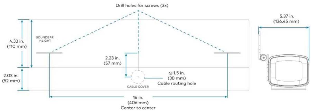
text_image
Drill holes for screws (3x) 4.33 in. (110 mm) SOUNDBAR HEIGHT 2.03 in. (52 mm) 2.23 in. (57 mm) CABLE COVER Ø 1.5 in. (38 mm) Cable routing hole 16 in. (406 mm) Center to center 5.37 in. (136.45 mm)-
Drill three holes for the 1.25 in. (32 mm) wall screws and one 1.5 in. (38 mm) hole for cable routin as shown in the diagram.
-
Install the three included wall anchors into the drilled holes. Then, insert the anchor key to pop open and lock the anchors behind the hollow wall (not required for thick or solid walls).
-
Position the wall mounting bracket over the anchors, and insert the 1.25 in. (32 mm) screws into the holes.
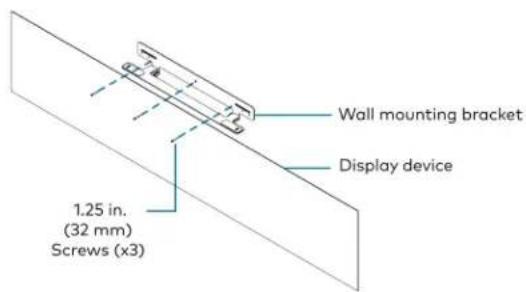
text_image
Wall mounting bracket Display device 1.25 in. (32 mm) Screws (x3)- Tighten the screws with a #1 Philips screwdriver until the bracket is secured to the wall.
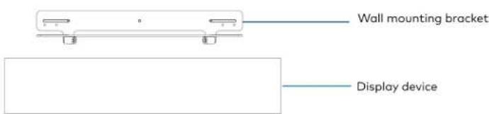
text_image
Wall mounting bracket Display device-
Place the videobar on the bracket aligning the screw holes on the bottom of the device with the holes on the bracket.
-
Insert the M5 X 16 mm hex screws (2062702) or M5 X 16 mm screws (2062699, security) from beneath the bracket and then through the holes on the bottom of the videobar.
-
Adjust the screws to keep the videobar secured to the bracket but do not tighten them.
-
Tilt the bracket down and place the videobar face down.
-
Route the cables through the cable cutout in the bracket and connect the cables to the videobar's ports as described in Connect.

text_image
Clestron Videobar 70 Cable Cable cutout Cables Wall mounting bracket Display device-
Place the videobar face up and tilt the bracket up.
-
Push the videobar back to lock it with the bracket.
-
Tighten the M5 X 16 mm hex screws (2062702) or M5 X 16 mm screws (2062699, security) from beneath the bracket to secure the videobar to the bracket.
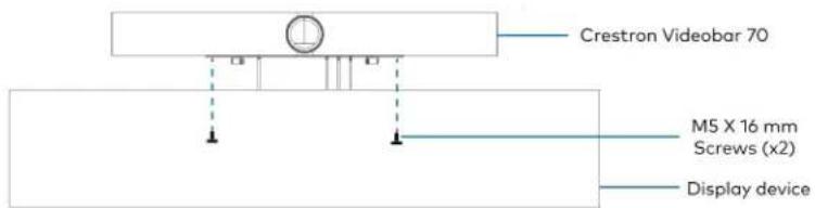
text_image
Crestron Videobar 70 M5 X 16 mm Screws (x2) Display device- Attach the magnetic cable shroud to the sound bar to hide the exposed connected wires and cables.

text_image
Crestron Videobar 70 Magnetic cable shroud Display deviceConnect
System Overview
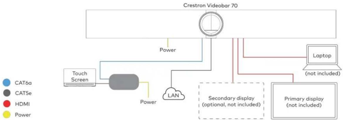
flowchart
graph TD
    A["Crestron Videobar 70"] --> B["Touch Screen"]
    B --> C["Power"]
    C --> D["LAN"]
    D --> E["Secondary display (optional, not included)"]
    E --> F["Laptop (not included)"]
    E --> G["Primary display (not included)"]
    style A fill:#f9f,stroke:#333
    style B fill:#ccf,stroke:#333
    style C fill:#cfc,stroke:#333
    style D fill:#fcc,stroke:#333
    style E fill:#cff,stroke:#333
    style F fill:#ffc,stroke:#333
    style G fill:#fcc,stroke:#333
Make Connections
- Make a direct connection for simple installation and setup by connecting the touch screen's PoE injector to the videobar.
Direct Connection
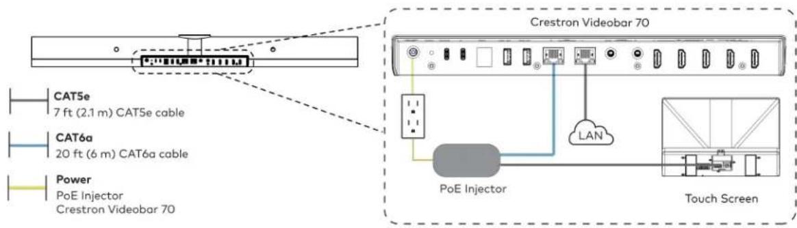
text_image
CAT5e 7 ft (2.1 m) CAT5e cable CAT6a 20 ft (6 m) CAT6a cable Power PoE Injector Crestron Videobar 70 Crestron Videobar 70 PoE Injector LAN Touch Screen- Make a network connection.
Network Connection

text_image
CAT5e 7 ft (2.1 m) CAT5e cable CAT6a 20 ft (6 m) CAT6a cable Power PoE Injector Crestron Videobar 70 Crestron Videobar 70 PoE Injector LAN LAN Touch Screen- Connect the displays (not included) to the videobar.

text_image
Crestron Videobar 70 HDMI Primary: 6 ft (1.8 m) HDMI cable (x2) Secondary display (optional, not included) Primary display (not included)- Connect a laptop (not included) to the videobar.
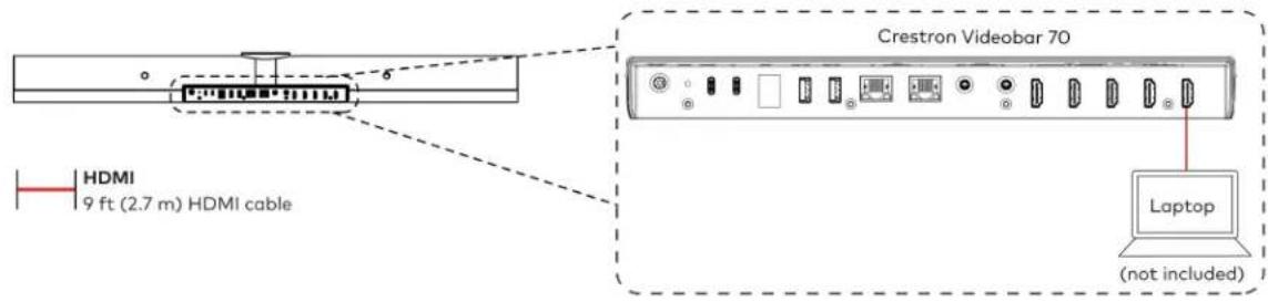
text_image
Crestron Videobar 70 HDMI 9 ft (2.7 m) HDMI cable Laptop (not included)Observe the LEDs
Refer to the following table for information about the LED indicators on the videobar.
| LED Indicator | Function Color Behavior Indication | |||
| LED Ring Mute | Red Solid Audio is muted. | |||
| Unmute Green | Solid Audio | is unmuted. | ||
| Booting Status | Green Blinking (1/4s On, 1/4s Off) The videobar is under booting process. | |||
| Firmware Status | Green Blinking (1s On, 1s Off) The firmware is being updated. | |||
Factory Restore
To factory restore the videobar:
- Ensure the videobar is connected to the display to view the restore process.
- Press and hold the recessed RESET button on the back of the videobar (using a paper clip or a similar tool) for ten seconds to initiate the factory restore.
- Release the button when the "Factory Data Reset" message appears on the display. The system will display a black screen if the RESET button is not released when the "Factory Data Reset" message is displayed. Power cycle and repeat step 1.
NOTE: The factory restore erases all user data, and the videobar returns to its initial booting status.
- After rebooting, perform a soft restore using the web UI to enable the authentication again.
Configure
Apply Power
Apply power to the videobar and the other devices in the system.
Setup and Update the Videobar
- Connect the videobar to the internet to upgrade the firmware automatically.
- After the upgrade, a pairing code appears on the display to be entered on the connected touch screen.
- Enter the code to pair the touch screen with the display.
To factory restore the videobar:
- Ensure the videobar is connected to the display to view the restore process.
- Press and hold the recessed RESET button on the back of the videobar (using a paper clip or a similar tool) for ten seconds to initiate the factory restore.
- Release the button when the "Factory Data Reset" message appears on the display. The system will display a black screen if the RESET button is not released when the "Factory Data Reset" message is displayed. Power cycle and repeat step 1.
NOTE: The factory restore erases all user data, and the videobar returns to its initial booting status.
- After rebooting, perform a soft restore using the web UI to enable the authentication again.
Log In to the Zoom Rooms Service Using the Touch Screen
- Select Zoom Room Controller from the options to confirm the use of the touch screen as a Zoom Rooms controller, and tap Next.
- Enter the pairing code shown on the display to pair the touch screen with the videobar. The Zoom Rooms controller app is displayed.
- Tap Sign in to sign in to Zoom Rooms service with an activation code or email.
- Activation Code:
a. Tap Enter Activation Code.
b. Enter the 16-digit activation code provided by the administrator to activate the Zoom Room that is assigned to the activation code. The Zoom Rooms Conference Room screen is shown on the display.
- Email:
a. Enter the email credentials and tap Sign In.
b. Select the conference room name from the list and tap Next. The Zoom Rooms Conference Room screen is shown on the display.
Configuration
This section provides the following information:
Zoom Rooms Deployment and Setup
Minimum Requirements
- A Zoom Rooms account or activation code is required to set up a Zoom Rooms system.
- Zoom Room administrator access is required to create and modify Zoom rooms.
Pre-Deployment Checklist
Complete the following tasks to ensure successful deployment of your Crestron® Flex conference room solution.
| TASK REQUIREMENT NOTES | ||
| Verify Accounts/Configure Solution | Zoom Rooms account credentials | When purchasing a Crestron Flex for use with Zoom Rooms, the Zoom Rooms desktop client is preinstalled on the UC-ENGINE.For guidelines on how to configure accounts for Zoom Rooms, visit Setup & Configuration on the Zoom Rooms Help Center. |
| Confirm Connection Points Two (2) Gigabit LAN Ports Ensure the installation space has two available gigabit LAN ports connected to the same VLAN on the same network. | ||
| Configure Network Server Configure your network to provide an IP address using DHCP. | Crestron Flex for Zoom Rooms does not require tabletop devices to communicate with the UC-Engine directly. Each device requires Internet access to the Zoom Cloud service. | |
| Establish Network Communications | Open the required TCP and UDP ports. | Open TCP ports 80, 443, 8801, and 8802. Open UDP ports 3478, 3479, and 8801 through 8810.For more information, visit Network Firewall or Proxy Server Settings for Zoom and Firewall Configuration for Zoom Rooms. |
Initial Setup
Connect and start your selected solution as described in Installation and Connections on page 296. For detailed instructions on planning, deploying, and managing the Zoom Rooms system, visit Zoom's Documentation.
Zoom Rooms Software Updates
- UC Engine Firmware: Updates for the UC Engine in a Zoom Rooms configuration can be performed through the UC Engine's Windows Update service.
- Zoom Rooms software: Receives updates from the Zoom portal or through the Windows Update service.
- Touch Screen control device: Receives application updates from the Zoom portal and both application and firmware updates through the Crestron auto-update service.
- Crestron Mercury control device: Crestron Mercury control devices in Zoom Rooms Video mode will receive the application update from either the Windows Update service or when the Zoom Rooms software is updated in the Zoom portal. Firmware updates will be delivered through the Crestron auto-update service.
NOTE: A user requires an admin login to update an application or firmware using the Windows Update service.
Crestron Settings App
After setting up Zoom Rooms, use the Crestron Settings app for further configuration. A USB keyboard and mouse are required to use the Crestron Settings app.
NOTE: If a USB port is not available, temporarily disconnect the system's camera.
To open the Crestron Settings App:
- Connect a USB keyboard and mouse to a USB port on the UC Engine located on the bracket assembly.
- Press Ctrl + Alt + Del and select Sign Out. The login screen is shown.
Login Screen
text_image
CrestUC Sign In CreatUK Admin- Use the mouse and keyboard to click Admin and enter the administrator password (the default is "crestron"). The Windows desktop is displayed.
Windows Desktop

text_image
Recycle Bin 3:30 PM 2011/2020- Click > Crestron folder > Crestron Settings. The Crestron Settings app opens.
NOTE: When opening the Crestron Settings app for the first time, you must agree to the CRESTRON UNIFIED COMMUNICATIONS SOFTWARE LICENSE AGREEMENT. Click I Agree to continue to the Crestron Settings app.
Crestron Settings App

Settings
System
USB Camera
Content Input
IP Table
Diagnostics
Advanced
System Information
UC-ENGINE Unified Collaboration System [v1.00.16.804,#0879180]
© 2006-2019 Chevron Electrical Inc.
System Devices
Content Capture Device
The Ground Truth image displays a single, solid horizontal line. According to Rule 2 (UNDERSCORE & LINE RULES), this is a stylistic or background line, not a placeholder underscore. Therefore, the OCR result must ignore it. The provided OCR content is "____", which consists of four underscores. This is an incorrect interpretation of the line as a placeholder and violates the rule that stylistic lines must be ignored. The OCR has hallucinated text (underscores) where none should exist, violating the rule to ignore stylistic lines. Hence, the OCR result is inconsistent with the Ground Truth.
Sound Bar


Huddly IQ
1.2.17-84608
Installed Packages

Query Device Versions
Done
System
Use the System menu to view firmware versions of connected system devices and the firmware packages stored on the UC Engine.
System
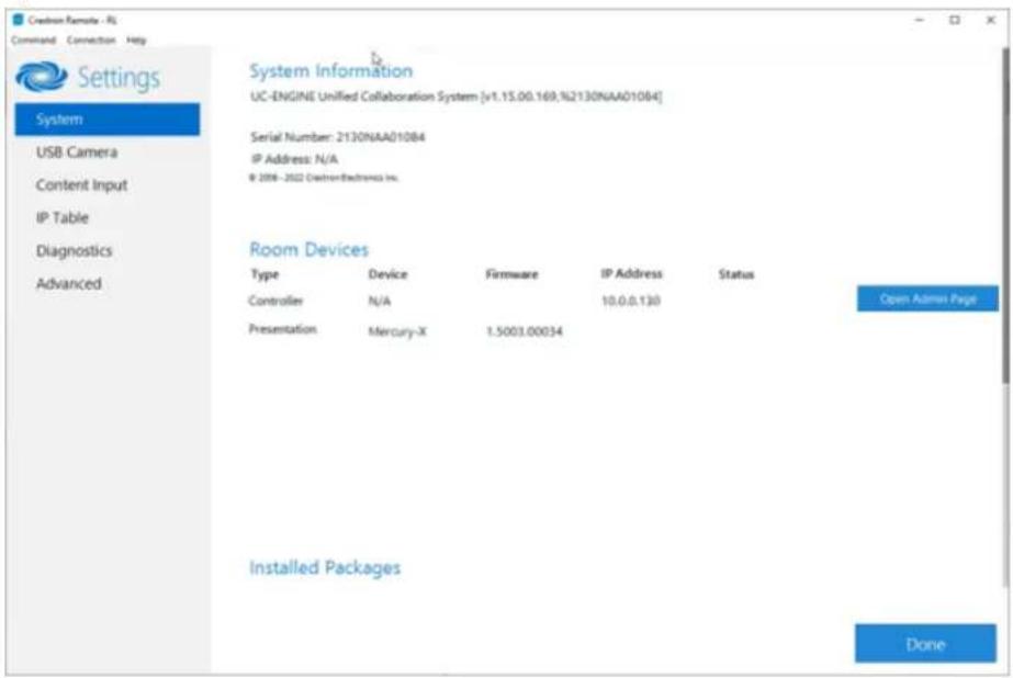
text_image
Creation Remote - RL Command Connection Help Settings System USB Camera Content Input IP Table Diagnostics Advanced System Information UC-ENGINE Unified Collaboration System [v1.15.00.169,%2130NAA010B4] Serial Number: 2130NAA010B4 IP Address: N/A © 2008 - 2022 CadtrionElectronics Inc. Room Devices Type Device Firmware IP Address Status Controller N/A 10.0.0.130 Open Admin Page Presentation Mercury-X 1.5003.00034 Installed Packages DoneClick Query Device Versions to view the firmware versions of the connected system devices.
Click Done to exit the Crestron Settings app. The Windows desktop is displayed.
USB Camera
Click USB Camera to display the USB Camera menu.
Use the USB Camera menu to adjust the zoom, tilt, and pan, recall preset settings, store preset settings, and control the Genius Framing feature (available for specific cameras).
USB Camera
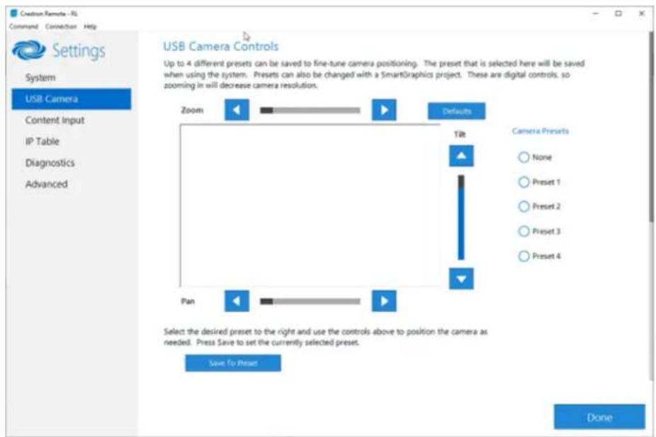
text_image
Creation Camera - RS Command Connection Help Settings System USB Camera Content Input IP Table Diagnostics Advanced USB Camera Controls Up to 4 different presets can be saved to fine-tune camera positioning. The preset that is selected here will be saved when using the system. Presets can also be changed with a SmartGraphics project. These are digital controls, so zooming in will decrease camera resolution. Zoom Defaults Tilt Camera Presets None Preset 1 Preset 2 Preset 3 Preset 4 Pan Select the desired preset to the right and use the controls above to position the camera as needed. Press Save to set the currently selected preset. Save to Preset DoneAdjust Tilt, Pan, or Zoom
The tilt, pan, and zoom on a connected camera can be remotely adjusted from the USB Camera screen.
NOTE: Tilt, pan, and zoom settings may not work with all cameras.
To adjust the tilt, pan, or zoom, select a preset and adjust as necessary.
- Click Zoom I or H to adjust the zoom.
- Click Pan I or H to adjust the pan.
- Click Tilt K or J to adjust the camera tilt.
- Click Defaults to return the camera to its default settings.
Save a Preset
Tilt, pan, and zoom settings can be saved for recall later. To save a preset setting:
- Click one of the four available Camera Presets locations on the right side of the display.
- Adjust the tilt, pan, and zoom as described in Adjust Tilt, Pan, or Zoom on page 444.
- Click Save To Preset to save the settings.
Recall a Preset
Click a Preset on the right side to recall a preset.
Genius Framing (systems with a CCS-CAM-USB-F-400 or UC-SB1-CAM-FLEX)
Crestron Flex solutions that use a CCS-CAM-USB-F-400 Huddy IQ Collaboration Camera or a UC-SB1-CAM-FLEX UC Video Conference Smart Soundbar & Camera can use the camera's built-in Genius Framing feature. Genius Framing automatically detects and frames people in the camera's field of view.
By default, Genius Framing is set to ON. Set the switch to OFF to disable Genius Framing.
NOTE: Genius Framing can be controlled by the XiO Cloud service if the UC Engine is registered with the service.
Content Input
Click Content Input to display information about the HDMI content input.
Content Input
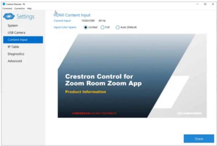
text_image
Crestron Remote - UI Command Connection Help Settings System USB Camera Content Input IP Table Diagnostics Advanced HDMI Content Input Current Input: 1920x1080 60 Hz Input Color Space: Limited Full Auto (Default) Crestron Control for Zoom Room Zoom App Product Information CONFIDENTIAL DO NOT DISTRIBUTE DoneSelect one of the following settings of the Input Color Space feature:
- Limited: Select if the black portion of the image appears washed out.
• Full: Select if the shadow detail of the picture appears missing.
• Auto (Default): Default setting (selected by default).
IP Table
Click IP Table to display the IP Table menu.
Configure the IP table to allow Crestron Flex to be used as part of a Crestron control system. An IP table is a lookup table used by Crestron Ethernet devices to map between IP IDs and IP addresses. Use the IP Table menu to enable and configure the system for communication with a Crestron control system.
NOTE:
- A Crestron Flex's IP table can also be configured by Crestron Toolbox software. For more information, refer to the Crestron Toolbox help file.
- The touch screen's IP table must contain an entry for the control system. For more information, refer to the TSW-570, TSW-770, and TSW-1070 Product Manual (Doc. 8550) or TS-770 and TS-1070 Product Manual (Doc. 8555).
IP Table

text_image
Crestron Remote - RL Command Connection Help Settings System USB Camera Content Input IP Table Diagnostics Advanced Crestron IP Table IP ID Type Address Dev-ID Room ID Port Status IP ID: Type (Query: IP Address/Hostname: Room ID* Device ID (JNIR) * Port [41794]*) : Update Selected Remove Add * Entries are optional and if not specified, the default will be used. Automatically discover and respond to other Crestron devices On Allow multiple IP Table entries On DoneIP Table Entries
Entries in an IP table identify the control system(s) that can control Crestron Flex. Entries can be added, updated, or removed.
- Add an Entry
a. From the IP ID drop-down list, select the system's IP ID as specified in the control system's program.
NOTE: The IP ID must match the IP ID specified for the system in the control system's program.
b. Enter the IP address or hostname in the IP Address/Hostname field.
c. If using a port other than 41794 for communications with the control system, enter it in the Port (41794)* field.
NOTE: This field is optional. If left blank, the default port (41794) is used.
d. Click Add.
- Modify an Entry
a. Click an entry in the IP table.
b. Select the new IP ID, address or hostname, and port.
c. Click Update Selected.
- Remove an Entry
a. Click an entry in the IP table.
b. Click Remove.
Other IP Table Functions
Set the Automatically discover and respond to other Crestron devices setting to Off to hide the system from being discovered by other devices during Autodiscovery.
Multiple control systems listed on the IP table can be allowed to control the system. Set the Allow multiple IP Table entries setting to Off to allow only one control system on the IP table.
Crestron SSL
The system can use SSL technology when connecting to a Crestron control system. To configure the system to use SSL for control system communications:
- Set the Use SSL for control system connections setting to Enabled.
- If certificate authentication is used, set the Certificate Authentication setting to On.
- Enter the login credentials in the Username and Password fields.
Diagnostics
Click Diagnostics to display the Diagnostics menu.
Use the Diagnostics menu to view and manage system logs.
Diagnostics
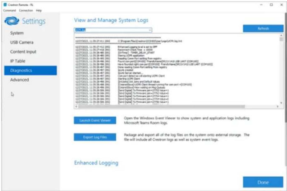
text_image
Crestron Remote - NS Command Connection Help Settings System USB Camera Content Input IP Table Diagnostics Advanced 1/4 View and Manage System Logs OK Web C:\Program Files\Crestron\CECRH03\userLog\UCR Log Int 12/07/08/25, 11:09:27:412 2003 12/07/08/25, 11:09:27:412 2003 12/07/08/25, 11:09:27:412 2003 12/07/08/25, 11:09:27:418 2003 12/07/08/25, 11:09:28:486 2003 12/07/08/25, 11:09:28:486 2003 12/07/08/25, 11:09:28:486 2003 12/07/08/25, 11:09:28:486 2003 Start (UOR) application Reading Conn Port setting from registry Found core port[OCR-000] Transfrika[OR-21143] USB unit [OCR-000] New Rounded right port[OCR-000] Transfrika[OR-21143] USB unit [OCR-000] Done reading Conn Port setting from registry Build created Local Server started... Can port detect as will starting UOR Client Starting UOR Client [Incloned] Init. Sets and Default values Clearfile[OCR Client thread running for core port +[OCR-000] Clearfile[OR row walking on Bag Qutual] Send Digital To Printware [prm=27752 Value+] Send Digital To Printware [prm=27754 Value+] Send Digital To Printware [prm=27754 Value+] Send Digital To Printware [prm=27758 Value+] - Launch Event Viewer Open the Windows Event Viewer to show system and application logs including Microsoft Teams Room logs. Export Log Film Package and export all of the log files on the system onto external storage. The file will include all Crestron logs as well as system event logs. Enhanced Logging DoneView Logs
When troubleshooting, different logs can be viewed. Select the desired log file from the View and Manage System Logs drop-down list to view a specific log type. Then, click Refresh to view the latest log data.
Windows Event Viewer
Click Launch Event Viewer to open the Windows event viewer that shows system and application logs.
Export Log Files
Click Export Log Files to package and export all the log files (including all Crestron logs and system event logs) onto external storage.
Upload Log Files
Click Upload Log Files to package and upload all the log files to a Crestron server for delivery to Crestron support personnel.
NOTE: Internet access is required for uploading.
Enhanced Logging
Enable the enhanced logging feature only if instructed by Crestron support for advanced troubleshooting. The enhanced logs are collected during the normal export process. Turn off enhanced logging when troubleshooting is finished.
Advanced
Click Advanced to display the Advanced menu.
Use the Advanced menu to configure the system with MyCrestron and Crestron Fusion software in the Cloud, to switch the UC Engine application mode, or to make the Soundbar firmware mode selection (UC-SB1-CAM-FLEX only).
Advanced
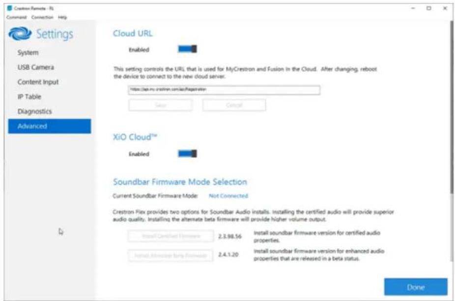
text_image
Creation Remote - FL Command Connection Help Settings System USB Camera Content Input IP Table Diagnostics Advanced Cloud URL Enabled This setting controls the URL that is used for MyCrestron and Fusion in the Cloud. After changing, reboot the device to connect to the new cloud server. https://doi.org/crestron.com/s/Registration Save Cancel XiO Cloud™ Enabled Soundbar Firmware Mode Selection Current Soundbar Firmware Mode Not Connected Crestron Flex provides two options for Soundbar Audio installs. Installing the certified audio will provide superior audio quality. Installing the alternate beta firmware will provide higher volume output. Install Certified Firmware 2.3.98.56 Install soundbar firmware version for certified audio properties. Install Minority bring Firmware 2.4.1.20 Install soundbar firmware version for enhanced audio properties that are released in a beta status. DoneCloud URL
Enter the URL of the Crestron Fusion server. Upon completion, the system should be brought into Crestron Fusion software as a processor. For more information, refer to the Crestron Fusion software help file.
UC-ENGINE Application Mode
Many Crestron Flex solutions that support dual displays can switch from the Zoom Rooms application to the Microsoft Teams Rooms.
NOTE: This functionality is supported by the ASUS UC engine only.
For more details on switching applications, refer to Switching from Zoom Rooms to Microsoft Teams Rooms on page 452.
Soundbar Firmware Mode Selection (for systems with UC-SB1-CAM-FLEX only) Crestron Flex with a UC-SB1-CAM-FLEX UC Video Conference Smart Soundbar can be used with firmware that provides superior sound quality or higher volume output.
If a soundbar is connected to the system, click a firmware version to install it.
Return to the Conference System
After all changes have been made, the system should be returned to regular operation. To return to regular operation:
- Click Done to return to the Windows desktop.
- Click A menu is displayed.
- Click 8 and then click Sign Out. The Administrator login screen is displayed.
- Click CrestUC.
- Click Sign in. The Zoom Rooms application will start.
NOTE: If a camera was disconnected from the UC Engine to use a keyboard, disconnect the keyboard and connect the camera to the UC Engine.
Switching from Zoom Rooms to Microsoft Teams Roc
NOTE: This functionality is supported by the ASUS UC engine only.
Minimum Firmware Requirements
• UC Engine: 1.00.16.715b
• TSW-1060 touch screen: 2.006.0063.001
• TS-1070 touch screen: 1.001.0014.001
• UC-2 Mini Tabletop conference device: 1.0.1.59
• CCS-UC-1-T-V Crestron Mercury Tabletop UC Video Conference System: 1.4906.00015.001
• CCS-UC-1-X Crestron Mercury X Tabletop Conference System: 1.4160.00050.001
Change UC Engine Settings
Use one of the following methods to change the UC Engine settings:
- Crestron Settings App
NOTES:
Some dual display systems cannot switch from the Zoom Rooms to the Microsoft Teams Rooms application. For example, if the Crestron Settings app does not show the Change to Teams button, the system does not support the mode switch function.
- If the XiO Cloud service manages the UC Engine, changes made in the Crestron Settings app will revert to the settings established by the XiO Cloud service.
- Crestron recommends using a keyboard and mouse connected to the UC Engine when using the Crestron Settings app. If a USB port is not available, temporarily disconnect the system's camera.
- Open the Crestron Settings app as described in Crestron Settings App on page 441.
- Click Advanced.
- Click Change to Teams and click Ok to confirm. The system will reboot.
- XiO Cloud Service
NOTE: Changes made from the XiO Cloud service will override any settings made from the Crestron Settings app.
- Log in to the XiO Cloud service and select the UC Engine to switch.
- Click the Settings tab.
XiO Cloud, UC Engine, Settings tab

text_image
United States > Flex Teams Systems > MSO-T HQ15-275 ✓ Action ✓ Status Settings Activity Log File Management File access is currently active + System Setup + Services + Applications Application Mode Zoom Rooms + CCS-CAM-USB-F-400 © 2020 Creather Devices Inc. Service Status | Privacy Statement | Create/Order- Click Applications.
NOTE: Some dual display systems cannot switch between the Zoom Rooms and the Microsoft Teams Rooms application. If the Settings tab does not contain an Applications menu, the system does not support the mode switch function.
- Click the checkbox next to Application Mode to have the XiO Cloud service manage the device
- Select Teams Video from the Application Mode drop-down list.
XiO Cloud, UC Engine, Settings tab, Teams Video selected

text_image
United States > Flex Teams Systems > M150-T HQ15-275 ✓ Save Charges ✓ Status Settings Activity Log File Management The stream is currently active • System Setup • Services • Applications Application Mode Team Video • CCS-CAM-USB-F-400 © 2020Cerner Electronics Inc. Service Status | Privacy Statement | Channels/Actions- Click Save Changes. The device will reboot.
Change the Control Device's Application Mode
Set the control device's Application Mode to Teams Video on:
Crestron Mercury Conference Systems
Use one of the following methods to change the Mercury conference system's application mode.
- Web Browser
NOTE: If the XiO Cloud service manages the Crestron Mercury device, any changes made in the web browser will revert to the settings established by the XiO Cloud service.
- Use a web browser to display the DEVICE screen of the Crestron Mercury device's configuration pages. For more information, refer to the CCS-UC-1 Product Manual (Doc. 7844).
Web browser, Crestron Mercury Device, Device menu, Applications

text_image
CRESTRON STATUS FORM INPUT FORM OUTPUT HC EXTRUM ACCESS APPEARCE AVR ANSORED Device/Management Auto Modules SIP Calling Configuration Data/Time Target for Software Administration Management Applications Application Mode: Open Access Zoom Frames Ultrave Video Percent: 10 Application Details Auto Update Custom Web © 2020 Crestron Electronics Inc.- Select Teams Video from the Application Mode drop-down list.
Web browser, Crestron Mercury Device, Device menu, Applications, Teams Video selected
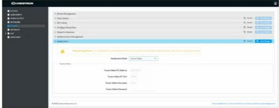
text_image
CRESTRON STATUS HOMSIPUT CHANNELS NETWORK ACCESS APPROACH AVS AIRCADO • Device Management • Audio Updates • TCP Calling • Configure DataFlow • Player For Business • Authentication Management • Application Mode Server Video Server Video PC Address Server Video PC Port Server Video Username Server Video Password © 2020 Crestron Devices, Inc. © 2020 Crestron 1. Crestron/Internet/Communication Software Command System-
Click Save Changes. The device will reboot.
-
If the Crestron Mercury device is using a direct Ethernet connection to the UC Engine, continue to Configuration on page 438. Otherwise, log in to the Crestron Mercury device and navigate to DEVICE > Applications.
Certain Crestron Flex running Microsoft Teams Rooms can use a direct Ethernet connection between the control device and a USB-to-Ethernet adapter (ADPT USB ENET) connected to the UC Engine to simplify the installation and configuration of the system. This method accelerates deployment, ensures reliability, and provides long-term service while eliminating network setup dependencies related to hardware and security requirements. For more information, refer to the system's quick start guide.
NOTE: Zoom Rooms systems and some Microsoft Teams Rooms systems do not have the ADPT USB ENET installed. The ADPT-USB-ENET is available for converting a Zoom Rooms system to a Microsoft Teams Rooms system using a direct Ethernet connection between the control device and the UC Engine. The ADPT USB ENET can also be used by those who would like to upgrade an existing Microsoft Teams Rooms system to support a direct Ethernet connection between the control device and the UC Engine.
- Enter the following information in the appropriate fields.
- Teams Video PC Address: Enter the IP address or hostname of the UC Engine.
NOTE: The hostname is printed on a label affixed to the UC Engine (mounted on the UC bracket assembly).
- Teams Video PC Port: By default, port number 49500 is used. If a different port number has been configured on the UC Engine, enter that port number instead.
- Teams Video Username: Enter the login username for the UC Engine. (the default is "admin")
° Teams Video Password: Enter the login password for the UC Engine. (the default is "sfb")
Web browser, Crestron Mercury Device, Device menu, Applications
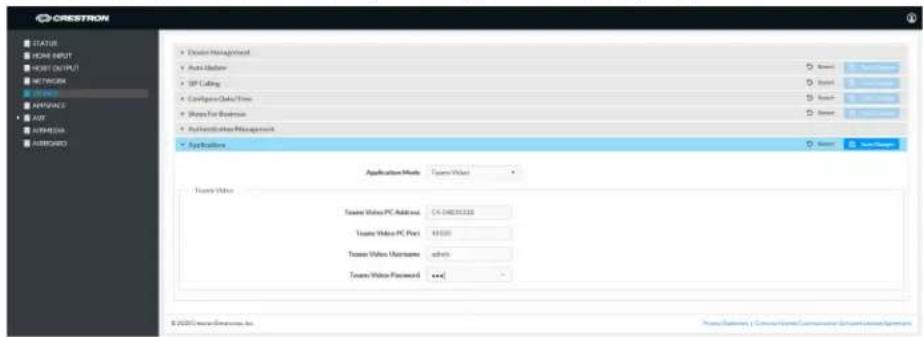
text_image
CRESTROW STATUS HOME INPUT HKEY OUTPUT NETWORK ACCESS IMPORTS AVR APPROACH ASSEMB • Address • AVR • NAME • NAME • Application Management Application Mode: Tissue Video Tissue Video PC Address: 04-04831110 Tissue Video PC Port: 49100 Tissue Video Username: admin Tissue Video Password: <+> © 2020 Crestris Software Inc.-
Click Save Changes.
-
Configure the system as described in Configuration on page 438.
- XiO Cloud Service
NOTE: Changes made from the XiO Cloud service will override any settings made from the device.
- Log in to the XiO Cloud service and select the Crestron Mercury device to switch.
- Click the Settings tab.
- Click Applications.
XiO Cloud, Crestron Mercury Device, Settings tab
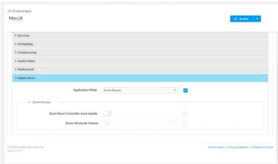
text_image
UC-ProductAgent MercX ✓ Action ✓ • Services • Scheduling • Conferencing • Audio-Video • PinPointUX • Applications Application Mode Zoom Rooms Zoom Rooms Zoom Room Controller Auto Update Zoom Ultrasonic Volume 70 © 2020 Crestron Electronics, Inc. Service Status | Privacy Statement | Cloudware License- Click the checkbox next to Application Mode to have the XiO Cloud service manage the device.
- Select Teams Video from the Application Mode drop-down list.
XiO Cloud, Crestron Mercury Device, Settings tab, Applications, Teams Video selected

text_image
UC-ProductAgent MercX Save Changes • Consulting • Conferencing • Audio-Video • PinPointUX • Applications Application Mode Teams Video • Microsoft Teams Video UC-ENGINE Address C4-54B203180F& UC-ENGINE Port 49500 UC-ENGINE Admin Username admin UC-ENGINE Admin Password **** © 2020Crisian Electronics Inc. Service Status | Privacy Statement | Cloudware License- Click Save Changes. The device will reboot.
- If the Crestron Mercury device is using a direct Ethernet connection to the UC Engine, continue to step 10. Otherwise, Click Applications.
- Enter the following information in the appropriate fields.
- Teams Video PC Address: Enter the IP address or hostname of the UC Engine.
NOTE: The hostname is printed on a label affixed to the UC Engine (mounted on the UC bracket assembly).
- Teams Video PC Port: By default, port number 49500 is used. If a different port number has been configured on the UC Engine, enter that port number instead.
° Teams Video Username: Enter the login username for the UC Engine. (the default is "admin") -
Teams Video Password: Enter the login password for the UC Engine. (the default is "sfb")
-
Click Save Changes.
-
Configure the system as described in Configuration on page 438.
Touch Screens
Use one of the following methods to change the touch screen's application mode.
- Web Browser
NOTE: If the touch screen is managed by the XiO Cloud service, any changes made in the web browser will revert to the settings established by the XiO Cloud service.
- Use a web browser to display the Applications settings of the touch screen's configuration pages. For more information, refer to the TSW-570, TSW-770, and TSW-1070 Product Manual (Doc. 8550) or TS-770 and TS-1070 Product Manual (Doc. 8555).
Web browser, Touch Screen Device, Settings tab, Applications

text_image
AVFFlex-TSW • 802.1x Configuration • Auto Update • Applications Application Mode Zoom Rooms Zoom Rooms Zoom Room Page Flip Distilled Time Out Control Disabled Flip To Project Flip to Zoom Rooms Flip Back Time Help Device Pairing © 2020 Crestron Devices, Inc.- Select Teams Video from the Application Mode drop-down list.
Web browser, Touch Screen Device, Settings tab, Applications, Teams Video selected

text_image
AVFFlex-TSW Auto Update Applications Microsoft Page Links, this will include Microsoft Page Video in the device to update that in 2016. This will request us to send. Application Mode: Teams Video Teams Video Teams Video PC Address: identical Teams Video PC Port: 47531 Teams Video Username: none Teams Video Password: Device Pulling © 2020 Crestron Devices, Inc.-
Click Save Changes. The device will reboot.
-
If the touch screen is directly connected to the UC Engine through a PWE-4803-RU, continue to step 7. Otherwise, log in to the touch screen's configuration pages and navigate to Settings > Applications.
-
Enter the following information in the appropriate fields.
- Teams Video PC Address: Enter the IP address or hostname of the UC Engine.
NOTE: The hostname is printed on a label affixed to the UC Engine (mounted on the UC bracket assembly).
- Teams Video PC Port: By default, port number 49500 is used. If a different port number has been configured on the UC Engine, enter that port number instead.
- Teams Video Username: Enter the login username for the UC Engine. (the default is "admin")
Teams Video Password: Enter the login password for the UC Engine. (T the default is "sfb")
Web browser, Touch Screen Device, Settings tab, Applications
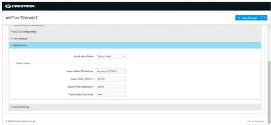
text_image
CRESTRON AVFFlex-TSW-d867 • 802.1x Configuration • Auto Update • Applications Application Mode Teams Video Team Video Team Video PC Address : Inbetuero123456 Team Video PC Port : 49000 Team Video Username admin Team Video Password : *** • Device Pinning © 2000 Cretion Electronics, Inc.-
Click Save Changes.
-
Configure the system as described in Configuration on page 438.
- XiO Cloud Service
NOTE: Changes made from the XiO Cloud service will override any settings made from the device.
- Log in to the XiO Cloud service and select the touch screen device to switch.
- Click the Settings tab.
- Click Applications.
XiO Cloud, Touch Screen Device, Settings tab

text_image
AVFFLEX-TSW System Setup Services Network Proxy Settings Audio Applications Application Mode Zoom Rooms Zoom Rooms Zoom Room Page Flip Time Out Control Disabled Flip To Project Flip To Mode Flip Back Time (In Minutes) 1 Minutes Control System- Click the checkbox next to Application Mode to have the XiO Cloud service manage the device.
- Select Teams Video from the Application Mode drop-down list.
XiO Cloud, Touch Screen Device, Settings tab, Teams Video selected
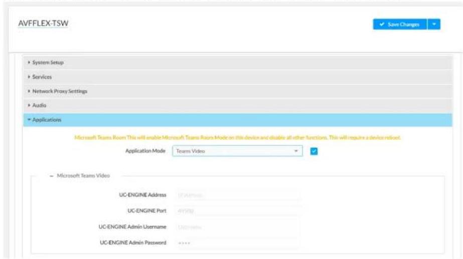
text_image
AVFFLEX-TSW System Setup Services Network Proxy Settings Audio Applications Microsoft Teams Room This will enable Microsoft Teams Room Mode on this device and disable all other functions. This will require a device reload. Application Mode Teams Video - Microsoft Teams Video UC-ENGINE Address 17A/10000 UC-ENGINE Port 49000 UC-ENGINE Admin Username Unknown UC-ENGINE Admin Password ****- Click Save Changes. The device will reboot.
- If the touch screen is directly connected to the UC Engine through a PWE-4803-RU, continue to step 10. Otherwise, log in to the touch screen's configuration pages and navigate to Settings > Applications.
- Enter the following information in the appropriate fields.
° Teams Video PC Address: Enter the IP address or hostname of the UC Engine.
NOTE: The hostname is printed on a label affixed to the UC Engine (mounted on the UC bracket assembly).
-
Teams Video PC Port: By default, port number 49500 is used. If a different port number has been configured on the UC Engine, enter that port number instead.
° Teams Video Username: Enter the login username for the UC Engine. (the default is "admin")
Teams Video Password: Enter the login password for the UC Engine. (the default is "sfb") -
Click Save Changes. The device will reboot.
-
Configure the system as described in Configuration on page 438.
Custom Controls on a Zoom Rooms System
A Zoom Rooms system with a touch screen can use a touch screen project for customized room control.
NOTE: Zoom Rooms systems with a Crestron Mercury Tabletop UC Video Conference cannot use a touch screen project for customized room control.
Use a web browser to configure the touch screen. For more information, refer to the TSW-570, TSW-770, and TSW-1070 Product Manual (Doc. 8550) or TS-770 and TS-1070 Product Manual (Doc. 8555).
-
On a computer, open a web browser to the IP address of the touch screen.
-
Log in to the device and navigate to Settings > Applications.
Web browser, Touch Screen Device, Settings tab, Applications
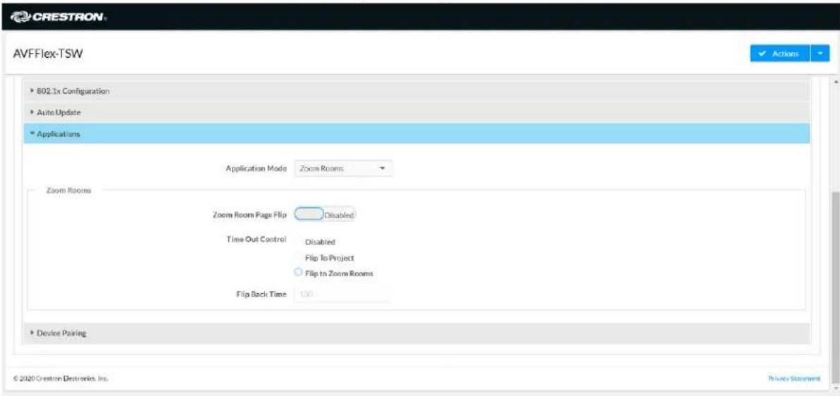
text_image
AVFFlex-TSW 802.1x Configuration Auto Update Applications Application Mode Zoom Rooms Zoom Rooms Zoom Room Page Flip Disabled Time Out Control Disabled Flip To Project Flip to Zoom Rooms Flip Back Time 100 Device Pairing © 2020 Crestron Electronics, Inc. Privacy Statement-
Set Zoom Room Page Flip to Enabled.
-
Set Time Out Control to the automatic flip behavior for the Zoom Rooms application.
- Disabled: Automatic flip behavior is disabled.
- Flip To Project: The screen automatically flips to the user project after the Flip Back Time duration elapses. Press the home button (second hard key from top right) on the touch screen to flip back to the Zoom Rooms application.
- Flip To Mode: The screen automatically flips to the Zoom Rooms application after the time out duration elapses. Press the home button on the touch screen to flip back to the user project.
- Set Flip Back Time to a time (1 to 100 minutes) before the automatic flip behavior occurs. Web browser, Touch Screen Device, Settings tab, Applications, Zoom Rooms selected
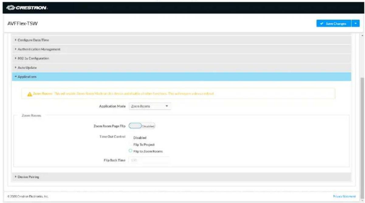
text_image
CRESTRON AVFFlex-TSW Configure Date/Time Authentication Management 802.1x Configuration Auto Update Applications Zoom Rooms: This will install Zoom Room Media on this device and/or optional functions. This will require a device to boost Application Mode Zoom Rooms Zoom Rooms Zoom Room Page Flip Disabled Time Out Control Disabled Flip To Project Flip to Zoom Rooms Flip Back Time 100 Device Pairing © 2020 Creation Electronics, Inc.-
Click Save Changes. The device will reboot.
-
Load the touch screen project to the touch screen as described in the TSW-570, TSW-770, and TSW-1070 Product Manual (Doc. 8550) or TS-770 and TS-1070 Product Manual (Doc. 8555).
Crestron Control for Zoom Rooms Software
Provides a program that can be loaded to a Crestron control system to enable custom programming and control for the Zoom Rooms controller application. Compatible with all Crestron Flex for Zoom Rooms solutions. For more information, visit Crestron Control for Zoom Rooms Software.
Operation
For instructions on using a Zoom Rooms solution, visit Getting Started with a Zoom Rooms Solution.
Open-Platform Solutions
Crestron Flex Open-platform solutions provide a complete conferencing and collaboration solution for open-platform UC applications. For more details, refer to Crestron Flex BYOD Solutions.
Select the following sections to know about the product features, specifications, and installation for all M50/MX50 and M70/MX70 series Open-platform solutions.
- Features
- Specifications and Dimension Drawings
• Installing Open-Platform Solutions
Features
Refer to the following sections for more information on the features provided by various Open-platform BYOD conference rooms solutions.
UC-M50-UA Features
The Crestron Flex UC-M50-UA provides an audio conference room solution for open-platform UC applications.
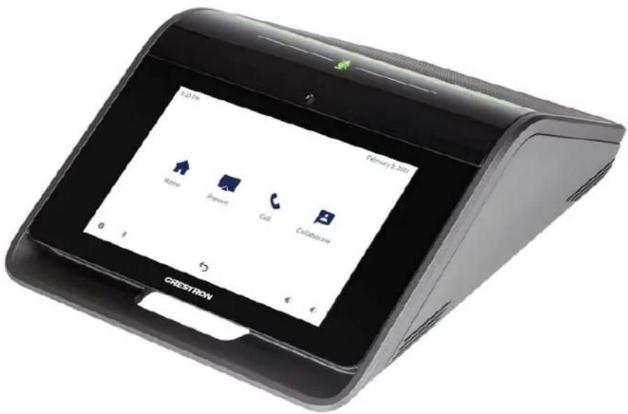
text_image
521m February 8, 2021 Home Remote Call Collaborative CRESTRONIncluded Components
- CCS-UC-1
• CBL-USB-A-BMICRO-6 - PW-2420RU
To view the specifications and dimensions of the included components of the selected kit, refer to Specifications and Dimension Drawings.
Key Features
• Tabletop audio conferencing solution for any UC platform
- Simple, intuitive touch screen UX provides a consistent user experience in every room
• Network management and provisioning and system alerts through the XiO Cloud® service
- Easy to specify and install — no custom design, programming, or software installation required
- Enterprise-grade security — connects and communicates securely over any enterprise or SMB network
• Premium-level support with Crestron Flex Care (optional)
Intuitive User Interface with Impressive Audio
With a large 7 in. HD color touch screen and an integrated AEC-enabled USB speakerphone that affords full-duplex wideband audio performance, the Crestron Flex Tabletop Conference device provides a superior conferencing and collaboration experience for meeting rooms, huddle spaces, and executive offices.
Voice Calling & Audio Conferencing
The tabletop conference device is a full-featured VoIP conferencing speakerphone that's fully compatible with major SIP-compliant phone systems. Its advanced design provides highly intelligible, full-duplex communication for every participant around a conference table. Dialing and answering calls is easy and intuitive using the large HD color touch screen. Corporate directory access (LDAP) enables one-touch dialing from the customer's centrally managed directory.
The conference device can pair with a mobile phone using Bluetooth® connectivity to make or join phone calls, or to use as a speaker and/or microphone for an application running on a smartphone. When used for calls, controls for the Bluetooth enabled phone appear on the touch screen, enabling instant connectivity with the press of a button.
The conference device functions like any USB Audio class device, allowing you to connect a laptop computer via USB to improve audio performance for any softphone, multimedia, or audio conferencing application running on the laptop.
Enterprise-Grade Security
Crestron Flex is an enterprise-grade solution that is ideally equipped for mass deployment throughout any sized corporate, university, medical, military, or government facility. Its advanced security features ensure privacy, reliability, and compliance with your organization's IT policies.
Easy Provisioning and Device Management
The XiO Cloud service is an IoT cloud based provisioning service (available separately) that enables installers and IT managers to deploy and manage thousands of devices easily. The XiO Cloud service allows for system alerts, network management and provisioning, and the pairing of a control device to the system's UC Engine. System updates are controlled by Windows software update.
Visit www.crestron.com/xiocloud for additional information.
Premium-Level Support
Crestron Flex Care is an optional subscription service that automatically renews annually, providing 24/7 live remote technical support, an extended five year warranty on Crestron hardware, expedited advance replacements, and a discounted rate for on-site support.
Visit www.crestron.com/flexcare for detailed terms and conditions and additional information.
UC-M50-U Features
The Crestron Flex UC-M50-U provides a complete conferencing and collaboration solution for open-platform UC applications. It supports a single video display.
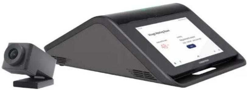
text_image
Wang Mobile Team 48° www.wang.com 48° www.wang.comIncluded Components
- CCS-UC-1-AV
• CCS-CAM-USB-F-400 - UC-CAM-WMK
- UC-HUB-USB
• STIRP - PW-2420RU
- Cables
To view the specifications and dimensions of the included components of the selected kit, refer to Specifications and Dimension Drawings.
Key Features
• Tabletop audio and video conferencing solution
- Simple, intuitive touch screen UX provides a consistent user experience in every room
- Present, call, conference, and collaborate using your own UC conference software (BYOD)
• Network management and provisioning and system alerts through the XiO Cloud® service
- Easy to specify and install — no custom design, programming, or software installation required
- Enterprise-grade security — connects and communicates securely over any enterprise or SMB network
• Premium-level support with Crestron Flex Care (optional)
Intuitive User Interface with Impressive Audio
With a large 7 in. HD color touch screen and an integrated AEC-enabled USB speakerphone that affords full-duplex wideband audio performance, the Crestron Flex Tabletop Conference device provides a superior conferencing and collaboration experience for meeting rooms, huddle spaces, and executive offices.
High-Definition Video Conferencing
The included collaboration camera (CCS-CAM-USB-F-400) features an ultra wide-angle 150° diagonal field of view to capture an entire conference room in Full HD 1080p video resolution. High precision aspherical optics, 12 MP CMOS sensor, and advanced video processing ensure a clear video image free from light or noise artifacts. Genius Framing digital autozoom detects the people in the room and frames them for an optimal view.
Voice Calling & Audio Conferencing
The tabletop conference device is a full-featured VoIP conferencing speakerphone that's fully compatible with major SIP-compliant phone systems. Its advanced design provides highly intelligible, full-duplex communication for every participant around a conference table. Dialing and answering calls is easy and intuitive using the large HD color touch screen. Corporate directory access (LDAP) enables one-touch dialing from the customer's centrally managed directory.
The conference device can pair with a mobile phone using Bluetooth® connectivity to make or join phone calls, or to use as a speaker and/or microphone for an application running on a smartphone. When used for calls, controls for the Bluetooth enabled phone appear on the touch screen, enabling instant connectivity with the press of a button.
The conference device functions like any USB Audio class device, allowing you to connect a laptop computer via USB to improve audio performance for any softphone, multimedia, or audio conferencing application running on the laptop.
BYOD Multimedia Presentation
Connect a display device to the CCS-UC-1-AV's HDMI ^® output port to enable high-definition video presentation from all types of BYOD sources.
Connect an AV source to the HDMI input port to present full-motion HD video content on the room display. Sources with DisplayPort™ or USB Type-C® outputs can also be connected using an optional Crestron video cable system (CBL-MULTI-6 or CBL-MULTI-12, sold separately).
Use the built-in AirMedia ^® technology for wireless presentation of content from a laptop, smartphone, or tablet device via the room's Wi-Fi ^® wireless network.
Visit www.crestron.com/airmedia for more information.
Video Conferencing & Web Collaboration
Videoconferencing is enabled by connecting a laptop running a web conferencing or UC application such as Microsoft Teams Rooms, Skype® for Business, Cisco Webex®, GotoMeeting®, Slack®, BlueJeans, or Zoom Rooms. All participants are provided with enhanced bidirectional audio along with a high-definition view of the whole room.
Connect the laptop's HDMI output to allow the whole room to view far-end content and camera images on the main room display. Laptops with DisplayPort or USB Type-C outputs can also be connected using an optional Crestron video cable system (CBL-MULTI-6 or CBL-MULTI-12, sold separately).
Enterprise-Grade Security
Crestron Flex is an enterprise-grade solution that is ideally equipped for mass deployment throughout any sized corporate, university, medical, military, or government facility. Its advanced security features ensure privacy, reliability, and compliance with your organization's IT policies.
Easy Provisioning and Device Management
The XiO Cloud service is an IoT cloud based provisioning service (available separately) that enables installers and IT managers to deploy and manage thousands of devices easily. The XiO Cloud service allows for system alerts, network management and provisioning, and the pairing of a control device to the system's UC Engine. System updates are controlled by Windows software update.
Visit www.crestron.com/xiocloud for additional information.
Premium-Level Support
Crestron Flex Care is an optional subscription service that automatically renews annually, providing 24/7 live remote technical support, an extended five year warranty on Crestron hardware, expedited advance replacements, and a discounted rate for on-site support.
Visit www.crestron.com/flexcare for detailed terms and conditions and additional information.
Note:
- AirMedia wireless presentation requires a wired network connection between the Crestron Mercury® console and an external Wi-Fi wireless access point (not included). Laptops may alternately connect to AirMedia using a wired Ethernet connection. Full-motion video performance is dependent upon the performance of the network and the sending device. Computer client software and mobile device apps are available for download at www.crestron.com/airmedia.
UC-MX50-U Features
The Crestron Flex UC-MX50-U provides a complete conferencing and collaboration solution for open-platform UC applications. It supports a single video display.
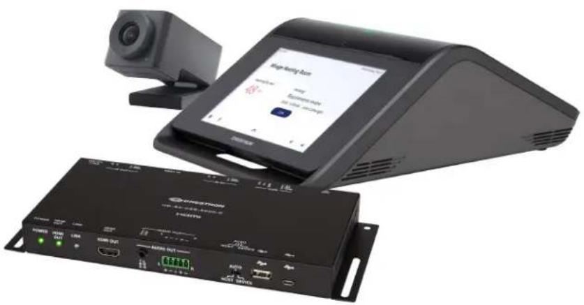
natural_image
Exterior view of a modern office building (no signage)Included Components
- CCS-UC-1-X
• CCS-CAM-USB-F-400 - UC-CAM-WMK
• HD-RX-USB-2000-C
• STIRP - Cables
To view the specifications and dimensions of the included components of the selected kit, refer to Specifications and Dimension Drawings.
Key Features
• Tabletop audio and video conferencing solution
- Simple, intuitive touch screen UX provides a consistent user experience in every room
• Present, call, conference, and collaborate using your own UC conference software (BYOD)
• Network management and provisioning and system alerts through the XiO Cloud® service
- Easy to specify and install — no custom design, programming, or software installation required
- Enterprise-grade security — connects and communicates securely over any enterprise or SMB network
• Premium-level support with Crestron Flex Care (optional)
Intuitive User Interface with Impressive Audio
With a large 7 in. HD color touch screen and an integrated AEC-enabled USB speakerphone that affords full-duplex wideband audio performance, the Crestron Flex Tabletop Conference device provides a superior conferencing and collaboration experience for meeting rooms, huddle spaces, and executive offices.
High-Definition Video Conferencing
The included collaboration camera (CCS-CAM-USB-F-400) features an ultra wide-angle 150° diagonal field of view to capture an entire conference room in Full HD 1080p video resolution. High precision aspherical optics, 12 MP CMOS sensor, and advanced video processing ensure a clear video image free from light or noise artifacts. Genius Framing digital autozoom detects the people in the room and frames them for an optimal view.
Voice Calling & Audio Conferencing
The conference device provides full-duplex conferencing speakerphone capabilities and is compatible with major SIP-compliant phone systems. Dialing and answering calls is easy and intuitive using the large HD color touch screen. Corporate directory access (LDAP) enables one-touch dialing from the customer's centrally-managed directory. Native Skype® for Business VoIP support enables one-touch join capability for scheduled Skype meetings (audio only), or you can place a Skype call using the directory or dial pad.
The conference device can pair with a mobile phone using Bluetooth® connectivity to make or join phone calls, or to use as a speaker and/or microphone for an application running on a smartphone. When used for calls, controls for the Bluetooth-enabled phone appear on the touch screen, enabling instant connectivity with the press of a button.
The conference device functions like any USB Audio Class device, allowing you to connect a laptop computer via USB to improve audio performance for any softphone, multimedia, or audio conferencing application running on the laptop.
BYOD Multimedia Presentation
Connect a display device to the HD-RX-USB-2000-C's HDMI output port to enable high-definition video presentation from all types of BYOD sources.
Connect an AV source to the CCS-UC-1-X's HDMI input port to present full-motion HD video content on the room display. Sources with DisplayPort™ or USB Type-C® outputs can also be connected using an optional Crestron video cable system (CBL-MULTI-6 or CBL-MULTI-12, sold separately).
Use the built-in AirMedia ^® technology for wireless presentation of content from a laptop, smartphone, or tablet device via the room's Wi-Fi ^® wireless network.
Visit www.crestron.com/airmedia for more information ^1 .
Video Conferencing & Web Collaboration
Videoconferencing is enabled by connecting a laptop running a web conferencing or UC application such as Microsoft Teams Rooms, Skype® for Business, Cisco Webex®, GotoMeeting®, Slack®, BlueJeans, or Zoom Rooms. All participants are provided with enhanced bidirectional audio along with a high-definition view of the whole room.
Connect the laptop's HDMI output to allow the whole room to view far-end content and camera images on the main room display. Laptops with DisplayPort or USB Type-C outputs can also be connected using an optional Crestron video cable system (CBL-MULTI-6 or CBL-MULTI-12, sold separately).
HDMI over CATx Receiver
The HDMI over CATx Receiver (HD-RX-USB-2000-C) receives uncompressed HDMI, CEC, RS-232, Ethernet, and IR signals sent from a Crestron Flex tabletop conference device (CCS-UC-1-X) through a single CAT typecable. Signals are broken out to relevant output ports for connection to the front-of-room display.
Enterprise-Grade Security
Crestron Flex is an enterprise-grade solution that is ideally equipped for mass deployment throughout any sized corporate, university, medical, military, or government facility. Its advanced security features ensure privacy, reliability, and compliance with your organization's IT policies.
Easy Provisioning and Device Management
The XiO Cloud service is an IoT cloud based provisioning service (available separately) that enables installers and IT managers to deploy and manage thousands of devices easily. The XiO Cloud service allows for system alerts, network management and provisioning, and the pairing of a control device to the system's UC Engine. System updates are controlled by Windows software update.
Visit www.crestron.com/xiocloud for additional information.
Premium-Level Support
Crestron Flex Care is an optional subscription service that automatically renews annually, providing 24/7 live remote technical support, an extended five year warranty on Crestron hardware, expedited advance replacements, and a discounted rate for on-site support.
Visit www.crestron.com/flexcare for detailed terms and conditions and additional information.
Notes:
-
AirMedia wireless presentation requires a wired network connection between the Crestron Mercury® console and an external Wi-Fi wireless access point (not included). Laptops may alternately connect to AirMedia using a wired Ethernet connection. Full-motion video performance is dependent upon the performance of the network and the sending device. Computer client software and mobile device apps are available for download at www.crestron.com/airmedia.
-
CAT5e or better.
UC-M70-UA Features
The Crestron Flex UC-M70-UA provides an audio conference room solution for open-platform UC applications.
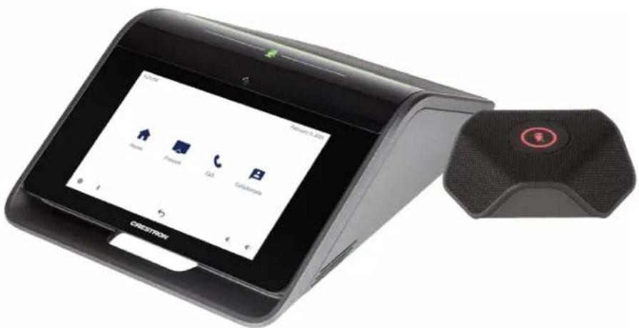
natural_image
Exterior view of a CRESTROI mobile phone with its sound output device (no visible text or symbols on the device body)Included Components
- CCS-UC-1
- CCS-UCA-MIC
• CBL-USB-A-BMICRO-6 - PW-2420RU
To view the specifications and dimensions of the included components of the selected kit, refer to Specifications and Dimension Drawings.
Key Features
• Tabletop audio conferencing solution for any UC platform
- Simple, intuitive touch screen UX provides a consistent user experience in every room
• Network management and provisioning and system alerts through the XiO Cloud® service
- Easy to specify and install — no custom design, programming, or software installation required
- Enterprise-grade security — connects and communicates securely over any enterprise or SMB network
• Premium-level support with Crestron Flex Care (optional)
Intuitive User Interface with Impressive Audio
With a large 7 in. HD color touch screen and an integrated AEC-enabled USB speakerphone that affords full-duplex wideband audio performance, the Crestron Flex Tabletop Conference device provides a superior conferencing and collaboration experience for meeting rooms, huddle spaces, and executive offices.
Voice Calling & Audio Conferencing
The tabletop conference device is a full-featured VoIP conferencing speakerphone that's fully compatible with major SIP-compliant phone systems. Its advanced design provides highly intelligible, full-duplex communication for every participant around a conference table. Dialing and answering calls is easy and intuitive using the large HD color touch screen. Corporate directory access (LDAP) enables one-touch dialing from the customer's centrally managed directory.
The conference device can pair with a mobile phone using Bluetooth® connectivity to make or join phone calls, or to use as a speaker and/or microphone for an application running on a smartphone. When used for calls, controls for the Bluetooth enabled phone appear on the touch screen, enabling instant connectivity with the press of a button.
The conference device functions like any USB Audio class device, allowing you to connect a laptop computer via USB to improve audio performance for any softphone, multimedia, or audio conferencing application running on the laptop.
Enterprise-Grade Security
Crestron Flex is an enterprise-grade solution that is ideally equipped for mass deployment throughout any sized corporate, university, medical, military, or government facility. Its advanced security features ensure privacy, reliability, and compliance with your organization's IT policies.
Easy Provisioning and Device Management
The XiO Cloud service is an IoT cloud based provisioning service (available separately) that enables installers and IT managers to deploy and manage thousands of devices easily. The XiO Cloud service allows for system alerts, network management and provisioning, and the pairing of a control device to the system's UC Engine. System updates are controlled by Windows software update.
Visit www.crestron.com/xiocloud for additional information.
Premium-Level Support
Crestron Flex Care is an optional subscription service that automatically renews annually, providing 24/7 live remote technical support, an extended five year warranty on Crestron hardware, expedited advance replacements, and a discounted rate for on-site support.
Visit www.crestron.com/flexcare for detailed terms and conditions and additional information.
UC-M70-U Features
The Crestron Flex UC-M70-U provides a complete conferencing and collaboration solution for open-platform UC applications. It supports a single video display.
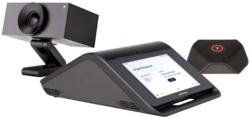
natural_image
Black video camera and sound recording device with a screen displaying app interface (no visible text or symbols on main components)Included Components
- CCS-UC-1-AV
- UC-CAM-L1
- CCS-UCA-MIC
• STIRP - PW-2420RU
- Cables
To view the specifications and dimensions of the included components of the selected kit, refer to Specifications and Dimension Drawings.
Key Features
• Tabletop audio and video conferencing solution
- Simple, intuitive touch screen UX provides a consistent user experience in every room
- Present, call, conference, and collaborate using your own UC conference software (BYOD)
• Network management and provisioning and system alerts through the XiO Cloud® service
- Easy to specify and install — no custom design, programming, or software installation required
- Enterprise-grade security — connects and communicates securely over any enterprise or SMB network
• Premium-level support with Crestron Flex Care (optional)
Intuitive User Interface with Impressive Audio
With a large 7 in. HD color touch screen and an integrated AEC-enabled USB speakerphone that affords full-duplex wideband audio performance, the Crestron Flex Tabletop Conference device provides a superior conferencing and collaboration experience for meeting rooms, huddle spaces, and executive offices.
High-Definition Video Conferencing
The included AI collaboration camera (UC-CAM ^1 features a wide-angle 103° diagonal field of view to capture an entire conference room in Full HD 1080p video resolution. High precision aspherical optics, 20.30 MP CMOS sensor, and advanced video processing ensure a clear video image free from light or noise artifacts. Genius Framing digital autozoom intelligently detects the people in the room and frames them for an optimal view.
Voice Calling & Audio Conferencing
The tabletop conference device is a full-featured VoIP conferencing speakerphone that's fully compatible with major SIP-compliant phone systems. Its advanced design provides highly intelligible, full-duplex communication for every participant around a conference table. Dialing and answering calls is easy and intuitive using the large HD color touch screen. Corporate directory access (LDAP) enables one-touch dialing from the customer's centrally managed directory.
The conference device can pair with a mobile phone using Bluetooth® connectivity to make or join phone calls, or to use as a speaker and/or microphone for an application running on a smartphone. When used for calls, controls for the Bluetooth enabled phone appear on the touch screen, enabling instant connectivity with the press of a button.
The conference device functions like any USB Audio class device, allowing you to connect a laptop computer via USB to improve audio performance for any softphone, multimedia, or audio conferencing application running on the laptop.
BYOD Multimedia Presentation
Connect a display device to the CCS-UC-1-AV's HDMI ^® output port to enable high-definition video presentation from all types of BYOD sources.
Connect an AV source to the HDMI input port to present full-motion HD video content on the room display. Sources with DisplayPort™ or USB Type-C® outputs can also be connected using an optional Crestron video cable system (CBL-MULTI-6 or CBL-MULTI-12, sold separately).
Use the built-in AirMedia ^® technology for wireless presentation of content from a laptop, smartphone, or tablet device via the room's Wi-Fi ^® wireless network.
Visit www.crestron.com/airmedia for more information.
Video Conferencing & Web Collaboration
Videoconferencing is enabled by connecting a laptop running a web conferencing or UC application such as Microsoft Teams Rooms, Skype® for Business, Cisco Webex®, GotoMeeting®, Slack®, BlueJeans, or Zoom Rooms. All participants are provided with enhanced bidirectional audio along with a high-definition view of the whole room.
Connect the laptop's HDMI output to allow the whole room to view far-end content and camera images on the main room display. Laptops with DisplayPort or USB Type-C outputs can also be connected using an optional Crestron video cable system (CBL-MULTI-6 or CBL-MULTI-12, sold separately).
Enterprise-Grade Security
Crestron Flex is an enterprise-grade solution that is ideally equipped for mass deployment throughout any sized corporate, university, medical, military, or government facility. Its advanced security features ensure privacy, reliability, and compliance with your organization's IT policies.
Easy Provisioning and Device Management
The XiO Cloud service is an IoT cloud based provisioning service (available separately) that enables installers and IT managers to deploy and manage thousands of devices easily. The XiO Cloud service allows for system alerts, network management and provisioning, and the pairing of a control device to the system's UC Engine. System updates are controlled by Windows software update.
Visit www.crestron.com/xiocloud for additional information.
Premium-Level Support
Crestron Flex Care is an optional subscription service that automatically renews annually, providing 24/7 live remote technical support, an extended five year warranty on Crestron hardware, expedited advance replacements, and a discounted rate for on-site support.
Visit www.crestron.com/flexcare for detailed terms and conditions and additional information.
Notes:
- The UC-CAM-L1 with network adapter requires driver installation on the connected laptop. A USB plug-and-play adapter, UC-CAMA-ADPT-ENET-USB, can be purchased separately to avoid driver installation.
- AirMedia wireless presentation requires a wired network connection between the Crestron Mercury® console and an external Wi-Fi wireless access point (not included). Laptops may alternately connect to AirMedia using a wired Ethernet connection. Full-motion video performance is dependent upon the performance of the network and the sending device. Computer client software and mobile device apps are available for download at www.crestron.com/airmedia.
UC-MX70-U Features
The Crestron Flex UC-MX70-U provides a complete conferencing and collaboration solution for open-platform UC applications. It supports a single video display.

natural_image
Product photo of a black video conference setup with a camera, display screen, and speaker (no visible text or symbols)Included Components
- CCS-UC-1-X
- UC-CAM-L1
- CCS-UCA-MIC
• HD-RX-USB-2000-C
• STIRP - Cables
To view the specifications and dimensions of the included components of the selected kit, refer to Specifications and Dimension Drawings.
Key Features
• Tabletop audio and video conferencing solution
- Simple, intuitive touch screen UX provides a consistent user experience in every room
• Present, call, conference, and collaborate using your own UC conference software (BYOD)
• Network management and provisioning and system alerts through the XiO Cloud® service
- Easy to specify and install — no custom design, programming, or software installation required
- Enterprise-grade security — connects and communicates securely over any enterprise or SMB network
- Premium-level support with Crestron Flex Care (optional)
Intuitive User Interface with Impressive Audio
With a large 7 in. HD color touch screen and an integrated AEC-enabled USB speakerphone that affords full-duplex wideband audio performance, the Crestron Flex Tabletop Conference device provides a superior conferencing and collaboration experience for meeting rooms, huddle spaces, and executive offices.
High-Definition Video Conferencing
The included AI collaboration camera (UC-CAM ^1 features a wide-angle 103° diagonal field of view to capture an entire conference room in Full HD 1080p video resolution. High precision aspherical optics, 20.30 MP CMOS sensor, and advanced video processing ensure a clear video image free from light or noise artifacts. Genius Framing digital autozoom intelligently detects the people in the room and frames them for an optimal view.
Voice Calling & Audio Conferencing
The conference device provides full-duplex conferencing speakerphone capabilities and is compatible with major SIP-compliant phone systems. Dialing and answering calls is easy and intuitive using the large HD color touch screen. Corporate directory access (LDAP) enables one-touch dialing from the customer's centrally-managed directory. Native Skype® for Business VoIP support enables one-touch join capability for scheduled Skype meetings (audio only), or you can place a Skype call using the directory or dial pad.
The conference device can pair with a mobile phone using Bluetooth® connectivity to make or join phone calls, or to use as a speaker and/or microphone for an application running on a smartphone. When used for calls, controls for the Bluetooth-enabled phone appear on the touch screen, enabling instant connectivity with the press of a button.
The conference device functions like any USB Audio Class device, allowing you to connect a laptop computer via USB to improve audio performance for any softphone, multimedia, or audio conferencing application running on the laptop.
BYOD Multimedia Presentation
Connect a display device to the HD-RX-USB-2000-C's HDMI output port to enable high-definition video presentation from all types of BYOD sources.
Connect an AV source to the CCS-UC-1-X's HDMI input port to present full-motion HD video content on the room display. Sources with DisplayPort™ or USB Type-C® outputs can also be connected using an optional Crestron video cable system (CBL-MULTI-6 or CBL-MULTI-12, sold separately).
Use the built-in AirMedia ^® technology for wireless presentation of content from a laptop, smartphone, or tablet device via the room's Wi-Fi ^® wireless network.
Visit www.crestron.com/airmedia for more information.
Video Conferencing & Web Collaboration
Videoconferencing is enabled by connecting a laptop running a web conferencing or UC application such as Microsoft Teams Rooms, Skype® for Business, Cisco Webex®, GotoMeeting®, Slack®, BlueJeans, or Zoom Rooms. All participants are provided with enhanced bidirectional audio along with a high-definition view of the whole room.
Connect the laptop's HDMI output to allow the whole room to view far-end content and camera images on the main room display. Laptops with DisplayPort or USB Type-C outputs can also be connected using an optional Crestron video cable system (CBL-MULTI-6 or CBL-MULTI-12, sold separately).
HDMI over CATx Receiver
The HDMI over CATx Receiver (HD-RX-USB-2000-C) receives uncompressed HDMI, CEC, RS-232, Ethernet, and IR signals sent from a Crestron Flex tabletop conference device (CCS-UC-1-X) through a single CAT typecable. Signals are broken out to relevant output ports for connection to the front-of-room display.
Enterprise-Grade Security
Crestron Flex is an enterprise-grade solution that is ideally equipped for mass deployment throughout any sized corporate, university, medical, military, or government facility. Its advanced security features ensure privacy, reliability, and compliance with your organization's IT policies.
Easy Provisioning and Device Management
The XiO Cloud service is an IoT cloud based provisioning service (available separately) that enables installers and IT managers to deploy and manage thousands of devices easily. The XiO Cloud service allows for system alerts, network management and provisioning, and the pairing of a control device to the system's UC Engine. System updates are controlled by Windows software update.
Visit www.crestron.com/xiocloud for additional information.
Premium-Level Support
Crestron Flex Care is an optional subscription service that automatically renews annually, providing 24/7 live remote technical support, an extended five year warranty on Crestron hardware, expedited advance replacements, and a discounted rate for on-site support.
Visit www.crestron.com/flexcare for detailed terms and conditions and additional information.
Notes:
- The UC-CAM-L1 with network adapter requires driver installation on the connected laptop. A USB plug-and-play adapter, UC-CAMA-ADPT-ENET-USB, can be purchased separately to avoid driver installation.
- AirMedia wireless presentation requires a wired network connection between the Crestron Mercury® console and an external Wi-Fi wireless access point (not included). Laptops may alternately connect to AirMedia using a wired Ethernet connection. Full-motion video performance is dependent upon the performance of the network and the sending device. Computer client software and mobile device apps are available for download at www.crestron.com/airmedia.
- CAT5e or better.
Specifications and Dimension Drawings
Refer to the following sections for more information regarding the specifications and dimensions of the following devices.
Tabletop Conferencing Device Specifications
Device name: CCS-UC-1 / CCS-UC-1-AV / CCS-UC-1-X
Touch Screen 7 in. (178 mm) diagonal capacitive multi-touch TFT active matrix color LCD, 1280 x 800 pixels
Mic Mute Symbol and Light Bar (2) Capacitive buttons with bi-color LEDs, either button toggles between mute and unmute
AEC Limes Audio TrueVoice® acoustic echo cancellation, automatic mic mixing, automatic gain control, and dynamic noise reduction, full-duplex IEEE 1329 Type 1 compliant
Speaker Full range speaker;
Amplifier Power: 11 W; 95 dB SPL at 0.5 m maximum output; Frequency Response: 90 Hz to 22 kHz
Microphones 360° quad mic array; Pickup Range (typical): 20 ft (6 m)
Extension Microphones Supports two mic pods, model CCS-UCA-MIC (sold separately)
Occupancy Sensor 6 ft (1.83 m) PIR range in front of touch screen
Ethernet (CCS-UC-1, CCS-UC-1-AV) Dual-port 100 Mbps, auto-switching, auto-negotiating, auto-discovery, full/half duplex, DHCP, TCP/IP, UDP/IP, CIP, SSL, TLS, SSH, SFTP (SSH File Transfer Protocol), SRTP, IEEE 802.1X, Active Directory® authentication, LDAP, Kerberos, digest access authentication, password login, HTTPS secure provisioning, XiO Cloud client, primary port is IEEE 802.3at Type 2 PoE+ compliant
Ethernet (CCS-UC-1-X) 100 Mbps, auto-switching, autonegotiating, autodiscovery, full/half duplex, DHCP, TCP/IP, UDP/IP, CIP, SSL, TLS, SSH, SFTP (SSH File Transfer Protocol), SRTP, IEEE 802.1X, Active Directory authentication, digest access authentication, password login, XiO Cloud service, Microsoft Intune® client
USB USB 2.0 micro Type B device port, supports UAC for audio interface to UC Engine (cable included)
Power Options (CCS-UC-PoE+: IEEE 802.3at Type 2, Class 4 (25.5 W) PoE+ Powered Device 1, CCS-UC-1-AV)
NOTE: If the additional mic pod (CCS-UCA-MIC) is used, PoE+ cannot be used to power the device.
24VDC: 24VDC via external 100-240VAC, 50/60 Hz power pack, model PW-2420RU
Power (CCS-UC-1-X) 24VDC via external 100-240VAC, 50/60 Hz power pack, model PW-2420RU
NOTE: The CCS-UC-1-X cannot be powered by Power over Ethernet or PoE+.
Dimensions Height: 4.11 in. (104 mm)
Width: 8.92 in. (227 mm)
Depth: 12.74 in. (324 mm)
Weight 5.5 lb (2.5 kg)
Tabletop Conferencing Device Dimension Drawing

Camera Specifications
CCS-CAM-USB-F-400
Image Sensor 12 Megapixel 1/2.3 CMOS sensor
Lens High precision, ultra wide angle, six element aspherical glass lens
Field of View 150° diagonal, 120° horizontal, 90° vertical
Aperture f/2.8
Autozoom Genius Framing automatic lossless digital zoom intelligently frames around people in the room
Connectivity Plug-and-play USB 3.1
Resolution/FPS HD 1080p @ 30 fps
Dimensions Height: 1.40 in. (36 mm)
Width: 1.60 in. (41 mm)
Depth: 2.82 in. (72 mm)
Weight 4.2 oz (120 g)
UC-CAM-L1
Image Sensor 20.30 Megapixels 1 in. CMOS Sensor
Lens High precision, wide angle, aspherical glass lens
Field of View 103° diagonal, 92° horizontal, 65° vertical
Aperture f/2.9
Autozoom Genius Framing automatic lossless digital zoom intelligently frames around people in the room
Connectivity USB 3.0 port (via USB to PoE Adapter)
Power 5VDC power adapter
Resolution/FPS HD 1080p @ 30 fps
Dimensions Height: 2.1 in. (53 mm)
Width: 4.8 in. (122 mm)
Depth: 3.5 in. (89 mm)
Weight 1.3 lb (0.6 kg)
Microphone Pod Specifications
Model CCS-UCA-MIC
Communications A2B bus protocol, slave, synchronous data, multichannel I2S/TDM to I2S/TDM
Microphone Triple mic array with (3) cardioid electret elements
Pickup Range 20 ft (6 m) typical, 360°
Mic Mute (1) Capacitive button with bi-color LED, toggles between mute and unmute (affects all system mics)
Connectors (2) RJ9 4P4C connector, female
Power Powered via the conference device through the A2B bus
Dimensions Height: 0.97 in (25 mm)
Width: 3.81 in (97 mm)
Depth: 3.42 in (87 mm)
Microphone Pod Dimension Drawing
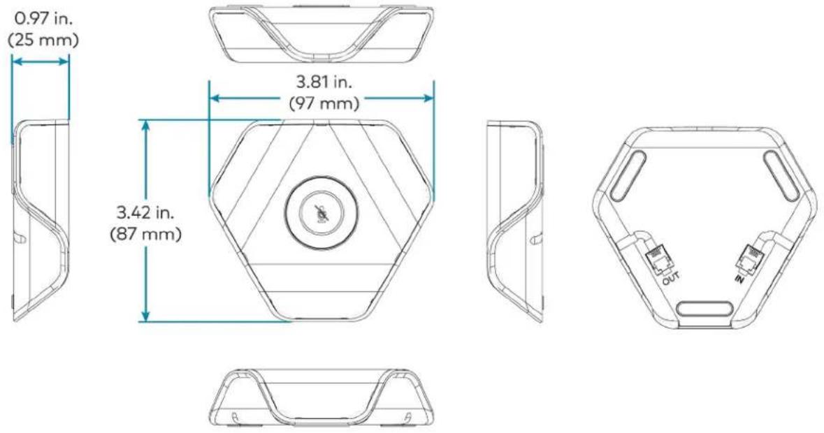
HDMI over CATx Receiver Specifications
Device name: HD-RX-USB-2000-C
Video Output Signal Types HDMI (DVI-compatible*)
* Requires CBL-HD-DVI interface cable (sold separately)
Audio Output Signal Types HDMI
Communications Ethernet: 100 Mbps pass-through;
USB: USB 2.0 pass-through for camera;
RS-232: 2-way serial pass-through up to 115.2k baud (Transmit Data/Receive Data only);
IR: IR signal pass-through up to 60 kHz;
HDMI: HDCP 2.2, EDID, CEC pass-through HDMI over CATx*: HDCP 2.2, EDID,
Ethernet, CEC/IR/RS-232
*CAT5e or better
Power Pack (included) Input: 0.8 A (maximum) @ 100-240 VAC, 50/60 Hz;
Output: 1.25 A @ 24 VDC;
Model: PW-2412WU
Dimensions Height: 4.47 in. (114 mm)
Width: 9.61 in. (244 mm)
Depth: 0.99 in. (25 mm)
Weight 1.71 lb (776 g)
HDMI over CATx Receiver Dimension Drawing
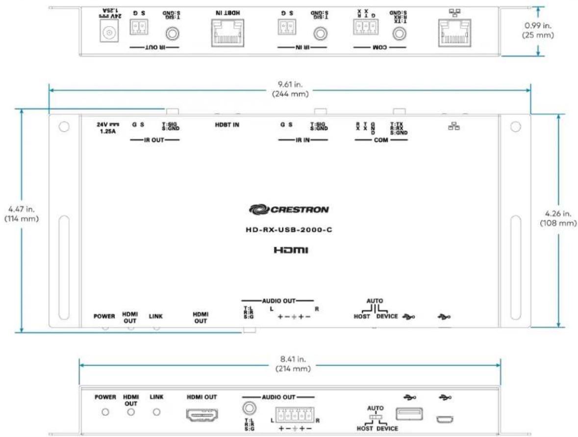
text_image
24V 1.25A HDBT IN G S T:SIG S:GND IR OUT G S T:SIG S:GND IR IN R T G X X N D T:TX R:RX S:GND COM 11X 6:MX Q 1 11X (25 mm) 0.99 in. (25 mm) 9.61 in. (244 mm) 4.47 in. (114 mm) 4.26 in. (108 mm) CRESTRON HD-RX-USB-2000-C HDMI POWER HDMI OUT LINK HDMI OUT AUDIO OUT L R S:G + - + + AUTO HOST DEVICE POWER HDMI OUT LINK HDMI OUT AUDIO OUT L R S:G + - + + AUTO HOST DEVICEInstalling Open-Platform Solutions
- Ensure you have received all the items mentioned in the In the Box section for your selected Microsoft Teams Rooms Crestron Flex solution.
- Mount all the devices applicable to your selected conferencing solution. For details, refer to Mounting Devices.
- Make connections for your selected conferencing solution. For details, refer to Connections.
In the Box
In the Box (UC-M50-UA)
| Qty. Description | |
| Mercury Tabletop Conference Device | |
| 1 | Tabletop Conference Device (6508227) |
| 1 | Cable, CAT5e, RJ-45 - RJ-45, 12 ft (3.7 m) (2033988) |
| 1 | Cable Retention Plate (2047908) |
| 3 | Tie Wrap (2047935) |
| Additional Items | |
| 1 | Cable, USB 2.0, A - Micro-B, 6 ft (1.8 m) (6510947) |
| 1 | Power supply (6500187) |
In the Box (UC-M50-U)
| Qty. Description | |
| Mercury Tabletop Conference Device | |
| 1 | Tabletop Conference Device (6508083) |
| 1 | Cable, CAT5e, RJ-45 - RJ-45, 12 ft (3.7 m) (2033988) |
| 1 | Cable Retention Plate (2047908) |
| 3 | Tie Wrap (2047935) |
| CCS-CAM-USB-F-400 Collaboration Camera | |
| 1 | Collaboration camera (6510482) |
| 1 | Camera wall mount kit (6510998) |
| Additional Items | |
| 1 | Cable, USB 2.0, A - Micro-B, 6 ft (1.8 m) (6510947) |
| 1 | Power supply (6500187) |
| 1 | Cable, USB 3.0, USB-C® Right Angle - A, 6 ft (1.8 m) (6511591) |
| 1 | Cable, thin HDMI®, 6 ft (1.8 m) (6510946) |
| 1 | Cable, HDMI, 20 ft (6.1 m) (6503567) |
| 1 | Cable, USB Extension, USB Type A Male-to-Female, 15 ft (4.6 m) (6508260) |
| 1 | IR Emitter Probe (6500940) |
In the Box (UC-MX50-U)
| Qty. Description | |
| Mercury Tabletop Conference Device | |
| 1 | Tabletop Conference Device (6510610) |
| 1 | Cable, CAT5e, RJ-45 - RJ-45, 12 ft (3.7 m) (2033988) |
| 1 | Power supply (2045873) with cord (2042043) |
| 1 | Cable Retention Plate (2047908) |
| 3 | Tie Wrap (2047935) |
| CCS-CAM-USB-F-400 Collaboration Camera | |
| 1 | Collaboration camera (6510482) |
| 1 | Camera wall mount kit (6510998) |
| HDMI® over CATx receiver | |
| 1 | HDMI® over CATx receiver (6510312) |
| Additional Items | |
| 1 | Cable, USB 2.0, A - Micro-B, 6 ft (1.8 m) (6510947) |
| 1 | Cable, USB 3.0, USB-C® Right Angle - A, 6 ft (1.8 m) (6511591) |
| 1 | Cable, thin HDMI®, 6 ft (1.8 m) (6510946) |
| 1 | IR Emitter Probe (6500940) |
| 1 | Cable, CAT6a, RJ-45 - RJ-45, 20 ft (6.1 m) (6507640) |
| 1 | Cable, HDMI 2.1, 6 ft (1.8 m) (6512150) |
In the Box (UC-M70-UA)
| Qty. Description | |
| Mercury Tabletop Conference Device | |
| 1 | Tabletop Conference Device (6508227) |
| 1 | Cable, CAT5e, RJ-45 - RJ-45, 12 ft (3.7 m) (2033988) |
| 1 | Cable Retention Plate (2047908) |
| 3 | Tie Wrap (2047935) |
| Microphone Pod | |
| 1 | Extension Microphone Pod (6508084) |
| Additional Items | |
| 1 | Cable, USB 2.0, A - Micro-B, 6 ft (1.8 m) (6510947) |
| 1 | Power supply (6500187) |
In the Box (C-M70-U)
| Qty. Description | |
| Mercury Tabletop Conference Device | |
| 1 | Tabletop Conference Device (6508083) |
| 1 | Cable, CAT5e, RJ-45 - RJ-45, 12 ft (3.7 m) (2033988) |
| 1 | Cable Retention Plate (2047908) |
| 3 | Tie Wrap (2047935) |
| CCS-CAM-L1 AI Collaboration Camera | |
| 1 | AI collaboration camera (6512296) |
| Microphone Pod | |
| 1 | Extension Microphone Pod (6508084) |
| Additional Items | |
| 1 | Cable, USB 2.0, A - Micro-B, 6 ft (1.8 m) (6510947) |
| 1 | Power supply (6500187) |
| 1 | Cable, thin HDMI®, 6 ft (1.8 m) (6510946) |
| 1 | Cable, HDMI, 20 ft (6.1 m) (6503567) |
| 1 | Cable, USB Extension, USB Type A Male-to-Female, 15 ft (4.6 m) (6508260) |
| 1 | IR Emitter Probe (6500940) |
In the Box (UC-MX70-U)
| Qty. Description | |
| Mercury Tabletop Conference Device | |
| 1 | Tabletop Conference Device (6510610) |
| 1 | Cable, CAT5e, RJ-45 - RJ-45, 12 ft (3.7 m) (2033988) |
| 1 | Power supply (2045873) with cord (2042043) |
| 1 | Cable Retention Plate (2047908) |
| 3 | Tie Wrap (2047935) |
| CCS-CAM-L1 AI Collaboration Camera | |
| 1 | AI collaboration camera (6512296) |
| HDMI® over CATx receiver | |
| 1 | HDMI® over CATx receiver (6510312) |
| Microphone Pod | |
| 1 | Extension Microphone Pod (6508084) |
| Additional Items | |
| 1 | Cable, USB 2.0, A - Micro-B, 6 ft (1.8 m) (6510947) |
| 1 | Cable, thin HDMI®, 6 ft (1.8 m) (6510946) |
| 1 | IR Emitter Probe (6500940) |
| 1 | Cable, CAT6a, RJ-45 - RJ-45, 20 ft (6.1 m) (6507640) |
| 1 | Cable, HDMI 2.1, 6 ft (1.8 m) (6512150) |
Mounting Devices
Mount the applicable devices based on your selected Crestron Flex solution.
Mounting CCS-UC-1 Tabletop Conference Device
The CCS-UC-1 Tabletop Conference Device can be placed on any flat surface or secured on a table using the CCS-UCA-SMK tabletop swivel mount kit (sold separately).
Mounting UC-CAM-L1
Mount the camera according to its included documentation.
Mounting CCS-CAM-USB-F-400
Mount the camera using the included UC-CAM-WMK wall mount kit.
The wall mount kit provides secure mounting options for CCS-CAM-USB-F-400. It comes with two mounting brackets and mounting hardware that allow for a variety of mounting locations.
In the Box (UC-CAM-WMK)
| Qty. Description | |
| 1 UC-CAM-WMK, Wall Mount Kit for CCS-CAM-USB-F-400 (6510998) | |
| Additional Items | |
| 2 Anchor, Wall, Plastic, #6 x 1-1/4 in. (2043585) | |
| 1 Bracket, Camera, 2.00 in. to 3.50 in. (51 mm to 89 mm) (2053562) | |
| 1 Bracket, Camera, 3.50 in. to 5.00 in. (89 mm to 127 mm) (2053561) | |
| 1 Screw, 1/4-20, 5/16 in., Flat Head, Phillips (2040253) | |
| 2 Screw, 6-AB x 1 in., Pan Head, Phillips, Black (2053606) | |
| 2 Tie Wrap, Releasable (2005430) | |
Installing the Wall Mount Kit
Select an appropriate mounting location and install the bracket.
Choose a Location
For optimal viewing results, the bracket should be mounted in a location that places the camera above the plane of the room's conference table.
Choose a Bracket
The wall mount kit comes with two brackets to accommodate a variety of mounting locations. The smaller bracket allows the back of the camera to be placed 2.00 in. to 3.50 in. (51 mm to 89 mm) off wall while the larger bracket allows the back of the camera to be placed 3.50 in. to 5.00 in. (89 mm to 127 mm) off the wall.
NOTES:
- The camera can be mounted on top of or under the bracket.
- When using the CCS-CAM-USB-F-100, the smaller bracket allows the back of the camera to be placed 2.25 in. to 3.00 in. (57 mm to 76 mm) off the wall while the larger bracket allows the back of the camera to be placed 3.75 in. to 4.55 in. (95 mm to 116 mm) off the wall.
Small bracket, CCS-CAM-USB-F-400 camera shown
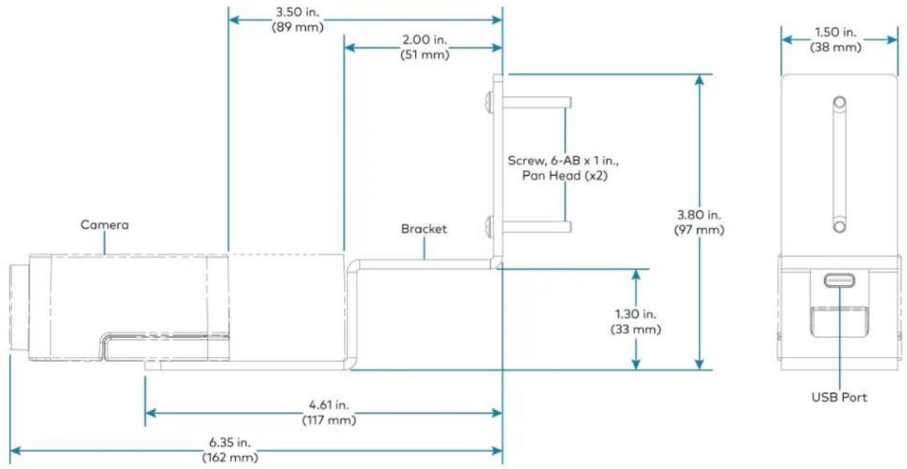
text_image
Camera 3.50 in. (89 mm) 2.00 in. (51 mm) Screw, 6-AB x 1 in., Pan Head (x2) Bracket 3.80 in. (97 mm) 1.50 in. (38 mm) 4.61 in. (117 mm) 6.35 in. (162 mm) USB PortLarge bracket, CCS-CAM-USB-F-400 camera shown
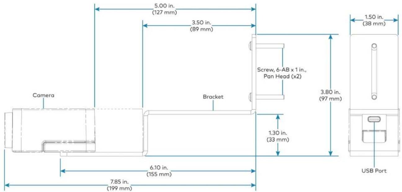
text_image
5.00 in. (127 mm) 3.50 in. (89 mm) Camera Bracket Screw, 6-AB x 1 in., Pan Head (x2) 1.50 in. (38 mm) 3.80 in. (97 mm) 1.30 in. (33 mm) 6.10 in. (155 mm) USB Port 7.85 in. (199 mm)Secure the Bracket
Secure the bracket to the mounting surface with the included 6-AB x 1 in. pan head screws. Use the included anchors for mounting locations where a stud cannot be found.
Secure the bracket (large bracket shown)
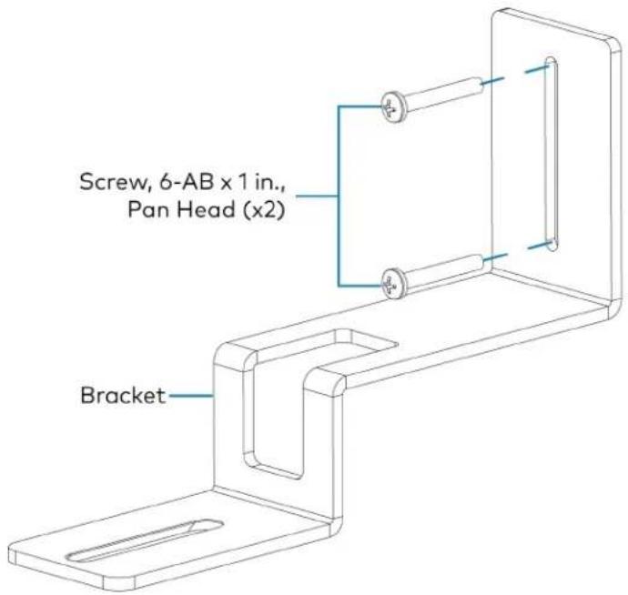
text_image
Screw, 6-AB x 1 in., Pan Head (x2) BracketAttach the Camera
Attach the camera to the bracket with the included 1/4-20, 5/16 in. flat head screw. The camera can be positioned forward and back along the bracket.
Attach the camera (large bracket with CCS-CAM-USB-F-400 camera shown)

text_image
HUB DLY Camera Notch Bracket Screw, 1/4-20, 5/16 in., Flat HeadConnect
Thread the cable that is included with the camera through the notch in the bracket and connect it to the camera's USB port and a USB device. Use the included tie wraps to secure excess cable.
NOTE: On the CCS-CAM-USB-F-100, the cable is attached to the camera.
Mounting HDMI ^® over CATx Receiver
The HD-RX-USB-2000-C may be installed up to 330 feet (100 meters) from the CCS-UC-1-X (depending on the video resolution and cable type). Video, audio, Ethernet, and control signals are all transported through a single CAT type cable (included with the UC-MX50-U and UC-MX70-U KIT) to the HD-RX-USB-2000-C.
Mounting CCS-UCA-MIC
The CCS-UCA-MIC extension microphone pod can be placed on the conference table or any flat surface.
Connections
UC-M50-UA Connections
Install the Cable Retention Plate
The included cable retention plate provides tie-down points for cables that connect to the Crestron® conference device.
Remove the adhesive backing from the cable retention plate and install the plate on the underside of the conference device as shown in the following diagram. Ensure the cable retention plate is firmly attached before securing cables.
CAUTION: When turning over the device, place the device on a soft surface to avoid damage.
NOTE: If a swivel mount kit (CCS-UCA-SMK) is to be used, use the cable retention bracket included with the swivel mount kit as described in the CCS-UCA-SMK DO Guide (Doc. 7882).

text_image
Install cable retention plate here Cable retention plate installedConnect
Make system connections as shown below:

text_image
CAT5e 12 ft CAT5e cable USB 6 ft USB 2.0 A - Micro-B cable Power Power supply Laptop Conference Device USB/ACG 24V DDR 2.5A 1 - MIC POD - 2 USB/CAM LAN LAN AIR COM HDMI OUT HDMI INBundle Cables
Bundle the cables together and use a provided tie wrap to secure the bundle to one of the positions on the cable retention plate at the rear of the device. Avoid bundling power and data cables together.
Insert the included USB cable into the respective cable channel as labeled on the underside of the conference device and as shown in the following image.

text_image
Route USB cable here Bundle remaining cables hereNOTES:
- When routing the USB cable through the channel out of the front of the device, the cable does not need to be bundled. If the system design requires routing the USB cable through the rear of the device, the cable should be bundled and secured to the cable retention plate.
- When using a swivel mount kit, do not route the USB cable through the swivel tube.
Configure
Configure the device using the web interface. To access the web interface, enter the device's IP address into a web browser. Select the gear icon in the upper right-hand corner of the screen and enter the username ("admin") and password ("admin") when prompted.
NOTE: To find the device's IP address, tap the information icon on the device's home screen.
For detailed configuration information, refer to the CCS-UC-1 Product Manual (Doc. 7844).
UC-M50-U Connections
Install the Cable Retention Plate
The included cable retention plate provides tie-down points for cables that connect to the Crestron® conference device.
Remove the adhesive backing from the cable retention plate and install the plate on the underside of the conference device as shown in the following diagram. Ensure the cable retention plate is firmly attached before securing cables.
CAUTION: When turning over the device, place the device on a soft surface to avoid damage.
NOTE: If a swivel mount kit (CCS-UCA-SMK) is to be used, use the cable retention bracket included with the swivel mount kit as described in the CCS-UCA-SMK DO Guide (Doc. 7882).
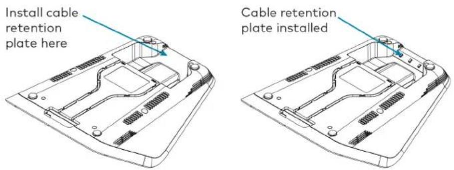
text_image
Install cable retention plate here Cable retention plate installedConnect
Make system connections as shown below:
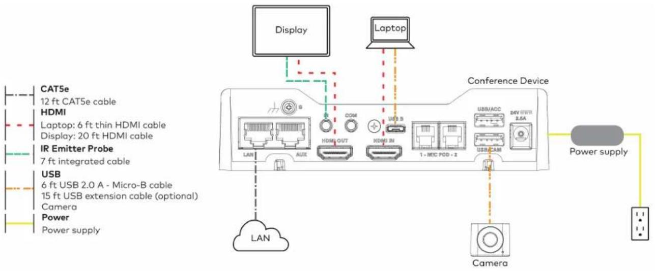
text_image
Display Laptop CAT5e 12 ft CAT5e cable HDMI Laptop: 6 ft thin HDMI cable Display: 20 ft HDMI cable IR Emitter Probe 7 ft integrated cable USB 6 ft USB 2.0 A - Micro-B cable 15 ft USB extension cable (optional) Camera Power Power supply LAN AUX COM HDMI OUT HDMI IN USB S 1 - MIC POD - 2 USB/ACC 2.5A USB/CAM Power supply LAN CameraBundle Cables
Bundle the cables together and use a provided tie wrap to secure the bundle to one of the positions on the cable retention plate at the rear of the device. Avoid bundling power and data cables together.
Insert the included USB and HDMI cables into their respective cable channels as labeled on the underside of the conference device and as shown in the following image.

text_image
Route USB cable here Bundle remaining cables here Route HDMI cable hereNOTES:
- When routing the USB and HDMI cables through the channels out of the front of the device, the cables do not need to be bundled. If the system design requires routing the USB and HDMI cables through the rear of the device, the cables should be bundled and secured to the cable retention plate.
- When using a swivel mount kit, do not route the USB and HDMI cables through the swivel tube.
Configure
Configure the device using the web interface. To access the web interface, enter the device's IP address into a web browser. Select the gear icon in the upper right-hand corner of the screen and enter the username ("admin") and password ("admin") when prompted.
NOTE: To find the device's IP address, tap the information icon on the device's home screen.
For detailed configuration information, refer to the CCS-UC-1 Product Manual (Doc. 7844).
UC-MX50-U Connections
Install the Cable Retention Plate
The included cable retention plate provides tie-down points for cables that connect to the Crestron® conference device.
Remove the adhesive backing from the cable retention plate and install the plate on the underside of the conference device as shown in the following diagram. Ensure the cable retention plate is firmly attached before securing cables.
CAUTION: When turning over the device, place the device on a soft surface to avoid damage.
NOTE: If a swivel mount kit (CCS-UCA-SMK) is to be used, use the cable retention bracket included with the swivel mount kit as described in the CCS-UCA-SMK DO Guide (Doc. 7882).
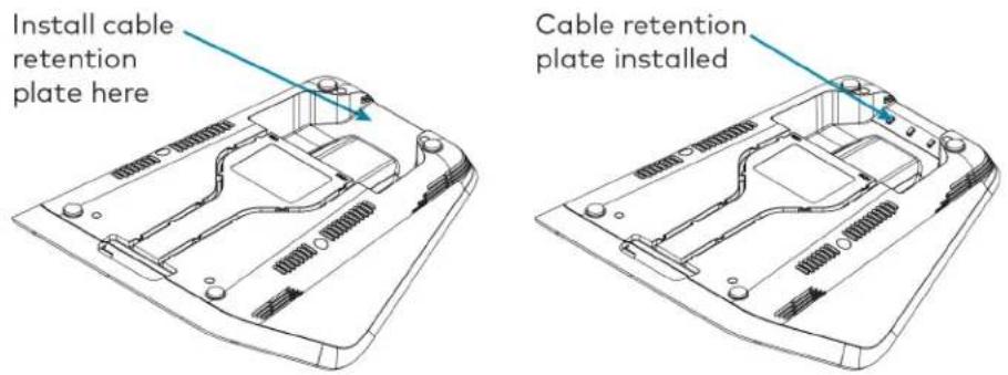
text_image
Install cable retention plate here Cable retention plate installedConnect
Make system connections as shown below:
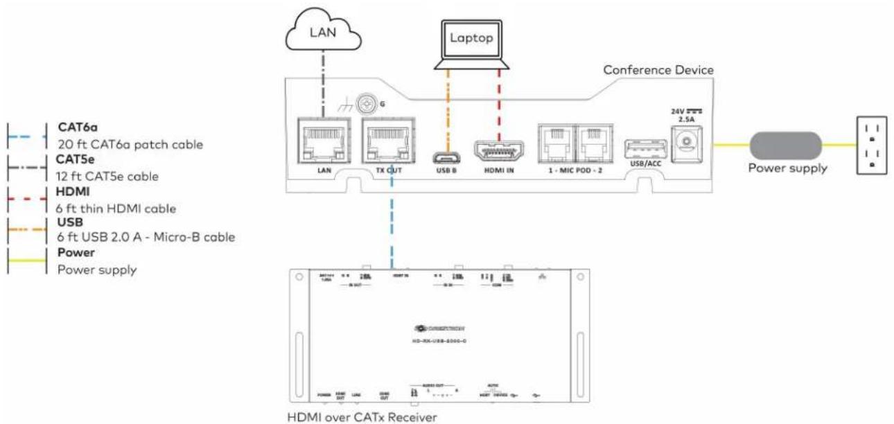
flowchart
graph TD
    A["CAT6a"] --> B["20 ft CAT6a patch cable"]
    C["CAT5e"] --> D["12 ft CAT5e cable"]
    E["HDMI"] --> F["6 ft thin HDMI cable"]
    G["USB"] --> H["6 ft USB 2.0 A - Micro-B cable"]
    I["Power"] --> J["Power supply"]
    K["Laptop"] --> L["Conference Device"]
    M["HDMI over CATx Receiver"] --> N["24V 2.5A"]
    O["Power supply"] --> P["Power supply"]
Make the remaining system connections as shown below:
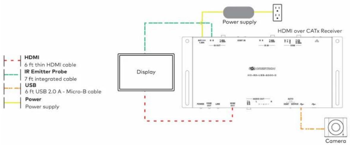
text_image
HDMI 6 ft thin HDMI cable IR Emitter Probe 7 ft integrated cable USB 6 ft USB 2.0 A - Micro-B cable Power Power supply Display Power supply Power supply HDMI over CATx Receiver HDMI 1.0A 1.0B 1.0C 1.0D 1.0E 1.0F 1.0G 1.0H 1.0I 1.0J 1.0K 1.0L 1.0M 1.0N 1.0O 1.0P 1.0Q 1.0R 1.0S 1.0T 1.0U 1.0V 1.0W 1.0X 1.0Y 1.0Z 1.0A 1.0B 1.0C 1.0D 1.0E 1.0F 1.0G 1.0H 1.0I 1.0J 1.0K 1.0L 1.0M 1.0N 1.0O 1.0P 1.0Q 1.0R 1.0S 1.0O 1.0P 1.0Y 1.0Z 1.0A 1.0B 1.0C 1.0D 1.0E 1.0F 1.0G 1.0X 1.0Y 1.0Z 1.0A 1.0B 1.0C 1.0D 1.0E 1.0F 1.0G 1.0X 1.0Y 1.0Z CameraBundle Cables
Bundle the cables together and use a provided tie wrap to secure the bundle to one of the positions on the cable retention plate at the rear of the device. Avoid bundling power and data cables together.
Insert the included USB and HDMI cables into their respective cable channels as labeled on the underside of the conference device and as shown in the following image.
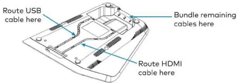
text_image
Route USB cable here Bundle remaining cables here Route HDMI cable hereNOTES:
- When routing the USB and HDMI cables through the channels out of the front of the device, the cables do not need to be bundled. If the system design requires routing the USB and HDMI cables through the rear of the device, the cables should be bundled and secured to the cable retention plate.
- When using a swivel mount kit, do not route the USB and HDMI cables through the swivel tube.
Configure
Configure the device using the web interface. To access the web interface, enter the device's IP address into a web browser. Select the gear icon in the upper right-hand corner of the screen and enter the username ("admin") and password ("admin") when prompted.
NOTE: To find the device's IP address, tap the information icon on the device's home screen.
For detailed configuration information, refer to the CCS-UC-1 Product Manual (Doc. 7844).
UC-M70-UA Connections
Install the Cable Retention Plate
The included cable retention plate provides tie-down points for cables that connect to the Crestron® conference device.
Remove the adhesive backing from the cable retention plate and install the plate on the underside of the conference device as shown in the following diagram. Ensure the cable retention plate is firmly attached before securing cables.
CAUTION: When turning over the device, place the device on a soft surface to avoid damage.
NOTE: If a swivel mount kit (CCS-UCA-SMK) is to be used, use the cable retention bracket included with the swivel mount kit as described in the CCS-UCA-SMK DO Guide (Doc. 7882).
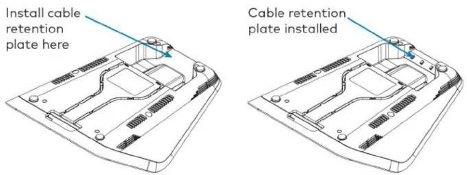
text_image
Install cable retention plate here Cable retention plate installedConnect
Make system connections as shown below:

text_image
Laptop Conference Device CAT5e 12 ft CAT5e cable Microphone 12 ft cable USB 6 ft USB 2.0 A - Micro-B cable Power Power supply LAN AUX RDMI OUT RDMI IN MIC POD - 2 USB/ACC 2.6A USB/CAM LAN Microphone Pod Power supplyBundle Cables
Bundle the cables together and use a provided tie wrap to secure the bundle to one of the positions on the cable retention plate at the rear of the device. Avoid bundling power and data cables together.
Insert the included USB cable into the respective cable channel as labeled on the underside of the conference device and as shown in the following image.
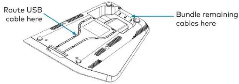
text_image
Route USB cable here Bundle remaining cables hereNOTES:
- When routing the USB cable through the channel out of the front of the device, the cable does not need to be bundled. If the system design requires routing the USB cable through the rear of the device, the cable should be bundled and secured to the cable retention plate.
- When using a swivel mount kit, do not route the USB cable through the swivel tube.
Configure
Configure the device using the web interface. To access the web interface, enter the device's IP address into a web browser. Select the gear icon in the upper right-hand corner of the screen and enter the username ("admin") and password ("admin") when prompted.
NOTE: To find the device's IP address, tap the information icon on the device's home screen.
For detailed configuration information, refer to the CCS-UC-1 Product Manual (Doc. 7844).
UC-M70-U Connections
Install the Cable Retention Plate
The included cable retention plate provides tie-down points for cables that connect to the Crestron® conference device.
Remove the adhesive backing from the cable retention plate and install the plate on the underside of the conference device as shown in the following diagram. Ensure the cable retention plate is firmly attached before securing cables.
CAUTION: When turning over the device, place the device on a soft surface to avoid damage.
NOTE: If a swivel mount kit (CCS-UCA-SMK) is to be used, use the cable retention bracket included with the swivel mount kit as described in the CCS-UCA-SMK DO Guide (Doc. 7882).

text_image
Install cable retention plate here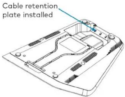
text_image
Cable retention plate installedConnect
Make system connections as shown below:
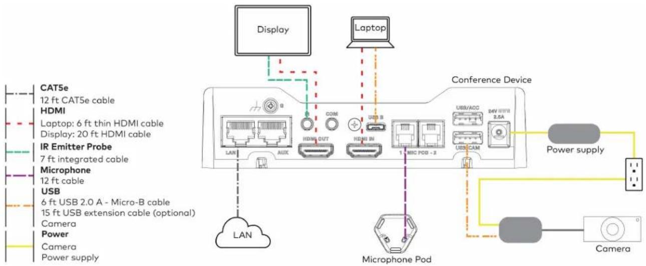
text_image
Display Laptop Conference Device CAT5e 12 ft CAT5e cable HDMI Laptop: 6 ft thin HDMI cable Display: 20 ft HDMI cable IR Emitter Probe 7 ft integrated cable Microphone 12 ft cable USB 6 ft USB 2.0 A - Micro-B cable 15 ft USB extension cable (optional) Camera Power Camera Power supply LAN AUX COM HDMI OUT HDMI IN 1 MIC PCI - 2 USB/ACC 24V DDR 2.5A USB/CAM Microphone Pod Power supply CameraBundle Cables
Bundle the cables together and use a provided tie wrap to secure the bundle to one of the positions on the cable retention plate at the rear of the device. Avoid bundling power and data cables together.
Insert the included USB and HDMI cables into their respective cable channels as labeled on the underside of the conference device and as shown in the following image.

text_image
Route USB cable here Bundle remaining cables here Route HDMI cable hereNOTES:
- When routing the USB and HDMI cables through the channels out of the front of the device, the cables do not need to be bundled. If the system design requires routing the USB and HDMI cables through the rear of the device, the cables should be bundled and secured to the cable retention plate.
- When using a swivel mount kit, do not route the USB and HDMI cables through the swivel tube.
Configure
Configure the device using the web interface. To access the web interface, enter the device's IP address into a web browser. Select the gear icon in the upper right-hand corner of the screen and enter the username ("admin") and password ("admin") when prompted.
NOTE: To find the device's IP address, tap the information icon on the device's home screen.
For detailed configuration information, refer to the CCS-UC-1 Product Manual (Doc. 7844).
UC-MX70-U Connections
Install the Cable Retention Plate
The included cable retention plate provides tie-down points for cables that connect to the Crestron® conference device.
Remove the adhesive backing from the cable retention plate and install the plate on the underside of the conference device as shown in the following diagram. Ensure the cable retention plate is firmly attached before securing cables.
CAUTION: When turning over the device, place the device on a soft surface to avoid damage.
NOTE: If a swivel mount kit (CCS-UCA-SMK) is to be used, use the cable retention bracket included with the swivel mount kit as described in the CCS-UCA-SMK DO Guide (Doc. 7882).

text_image
Install cable retention plate here Cable retention plate installedConnect
Make system connections as shown below:
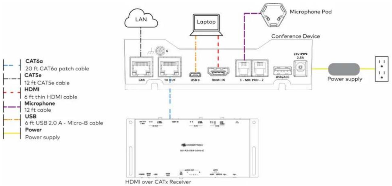
flowchart
graph TD
    A["CAT6a 20 ft CAT6a patch cable"] --> B["Laptop"]
    C["CAT5e 12 ft CAT5e cable"] --> B
    D["HDMI 6 ft thin HDMI cable"] --> B
    E["Microphone 12 ft cable"] --> B
    F["USB 6 ft USB 2.0 A - Micro-B cable"] --> B
    G["Power Power supply"] --> H["HDMI over CATx Receiver"]
    I["LAN"] --> J["Laptop"]
    K["TX OUT"] --> L["Conference Device"]
    M["USB B"] --> N["Conference Device"]
    O["HDMI IN"] --> P["Conference Device"]
    Q["1 - MIC POD - 2"] --> R["Conference Device"]
    S["USB/ACC"] --> T["Conference Device"]
    U["24V 2.5A"] --> V["Power supply"]
    W["Microphone Pod"] --> X["Conference Device"]
Make the remaining system connections as shown below:

flowchart
graph TD
    A["CAT5e or better"] --> B["Display"]
    C["HDMI"] --> B
    D["IR Emitter Probe"] --> B
    E["USB"] --> B
    F["Camera"] --> B
    G["Power"] --> B
    H["Camera"] --> B
    I["Power supply"] --> B
    J["Power supply"] --> B
    K["HDMI over CATx Receiver"] --> L["Device with LCD screen"]
    M["Camera"] --> N["Control panel"]
    style A fill:#f9f,stroke:#333
    style C fill:#f9f,stroke:#333
    style D fill:#f9f,stroke:#333
    style E fill:#f9f,stroke:#333
    style F fill:#f9f,stroke:#333
    style G fill:#f9f,stroke:#333
    style H fill:#f9f,stroke:#333
    style I fill:#f9f,stroke:#333
    style J fill:#f9f,stroke:#333
    style K fill:#f9f,stroke:#333
Bundle Cables
Bundle the cables together and use a provided tie wrap to secure the bundle to one of the positions on the cable retention plate at the rear of the device. Avoid bundling power and data cables together.
Insert the included USB and HDMI cables into their respective cable channels as labeled on the underside of the conference device and as shown in the following image.

text_image
Route USB cable here Bundle remaining cables here Route HDMI cable hereNOTES:
- When routing the USB and HDMI cables through the channels out of the front of the device, the cables do not need to be bundled. If the system design requires routing the USB and HDMI cables through the rear of the device, the cables should be bundled and secured to the cable retention plate.
- When using a swivel mount kit, do not route the USB and HDMI cables through the swivel tube.
Configure
Configure the device using the web interface. To access the web interface, enter the device's IP address into a web browser. Select the gear icon in the upper right-hand corner of the screen and enter the username ("admin") and password ("admin") when prompted.
NOTE: To find the device's IP address, tap the information icon on the device's home screen.
For detailed configuration information, refer to the CCS-UC-1 Product Manual (Doc. 7844).
Crestron Flex Accessories
This section lists available accessories for the select Crestron Flex products. For pricing and other details, refer to the product pages of the selected accessory.
• ADPT-USB3.0-GBENET
- ADPT-USB-ENET
- CCS-UCA-MIC
- CCS-UCA-SMK
ADPT-USB3.0-GBENET
The ADPT-USB3.0-GBENET is a USB-to-Ethernet Audio-over-IP (AoIP) isolation adapter for use with the UC-C100-T and UC-C100-T-WM kits. It isolates the AoIP traffic generated by in-room AoIP devices and the Shure® IntelliMix® Room digital signal processing (DSP) software from the rest of the network traffic on the UC-C100-T and UC-C100-T-WM kits.
The ADPT-USB3.0-GBENET supports up to 1000 Mbps transfer speed for reliable data transmission in a Crestron Flex system. LED indicators provide diagnostic information on the connection and data transfer.
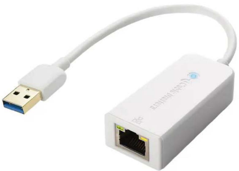
natural_image
White USB connector with network ports and cable, no visible text or symbols on the device bodyConnecting ADPT-USB3.0-GBENET
In the Box
Qty. Description
1 USB-to-Ethernet audio isolation adapter (6512671)
Connections
To connect the ADPT-USB3.0-GBENET adapter to the UC-C100-T or UC-C100-T-WM:
-
Make the UC-C100-T or UC-C100-T-WM kit connections. For detailed connection instructions, refer to the UC-C100-T and UC-C100-T-WM Connections section.
-
After making the kit connections, connect the adapter to the UC Engine, as shown in the following illustration.
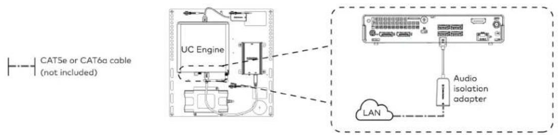
text_image
CAT5e or CAT6a cable (not included) UC Engine Audio isolation adapter LANNOTE: The USB port used to connect the ADPT-USB3.0-GBENET audio isolation adapter (shown in the above diagram) can also be used to connect a USB Audio device (as shown in the UC-C100-T and UC-C100-T-WM quick start guides), however, you can connect only one USB device at a time.
Configuring ADPT-USB3.0-GBENET
Set the IP Address
- Log into the UC-Engine Windows administrator account using the Crestron Remote application.
- Open Control Panel > Network and Internet > Network and Sharing Center and click Ethernet 2 > Properties.
-
Double click Internet Protocol Version 4 (TCP /IPv4) to open its properties.
-
The TCP /IPv4 settings can be set automatically or manually.
To specify the setting automatically:
a. Select Obtain an IP address automatically.
b. Select Obtain DNS server address automatically.

text_image
Network and Sharing Center Ethernet 2 Status Internet 2 Properties General Networking Sharing Connect using: Realtek U This connection Client fo File and Microso QoS Pa Bridge I Internet Microsoft Byb Install... Description Transmission f wide area net across diverse See also Internet Options Windows Defender Firewall Internet Protocol Version 4 (TCP/IPv4) Properties General Alternate Configuration You can get IP settings assigned automatically if your network supports this capability. Otherwise, you need to ask your network administrator for the appropriate IP settings. Obtain an IP address automatically Use the following IP address: IP add estw: . . . Sgnet mask: . . . Default gateway: . . . Obtain DNS server address automatically Use the following DNS server addresses: Preferred: . . . Alternate DNS server: . . . Valdate settings upon exit Advanced... OK Cancel Search Control Panel Internet Ethernet No Internet access Ethernet 2To specify the settings manually:
a. Select Use the following IP address and type the addresses in the IP address, Subnet mask, and Gateway fields.
b. Select Use the following DNS server addresses. and type the addresses in the Preferred DNS server and Alternate DNS server fields.
- Click OK to save the settings on each opened window until you return to the Ethernet 2 Status window.
- Click Details.
The Network Connection Details window appears.
- Verify that the correct IP address is set.
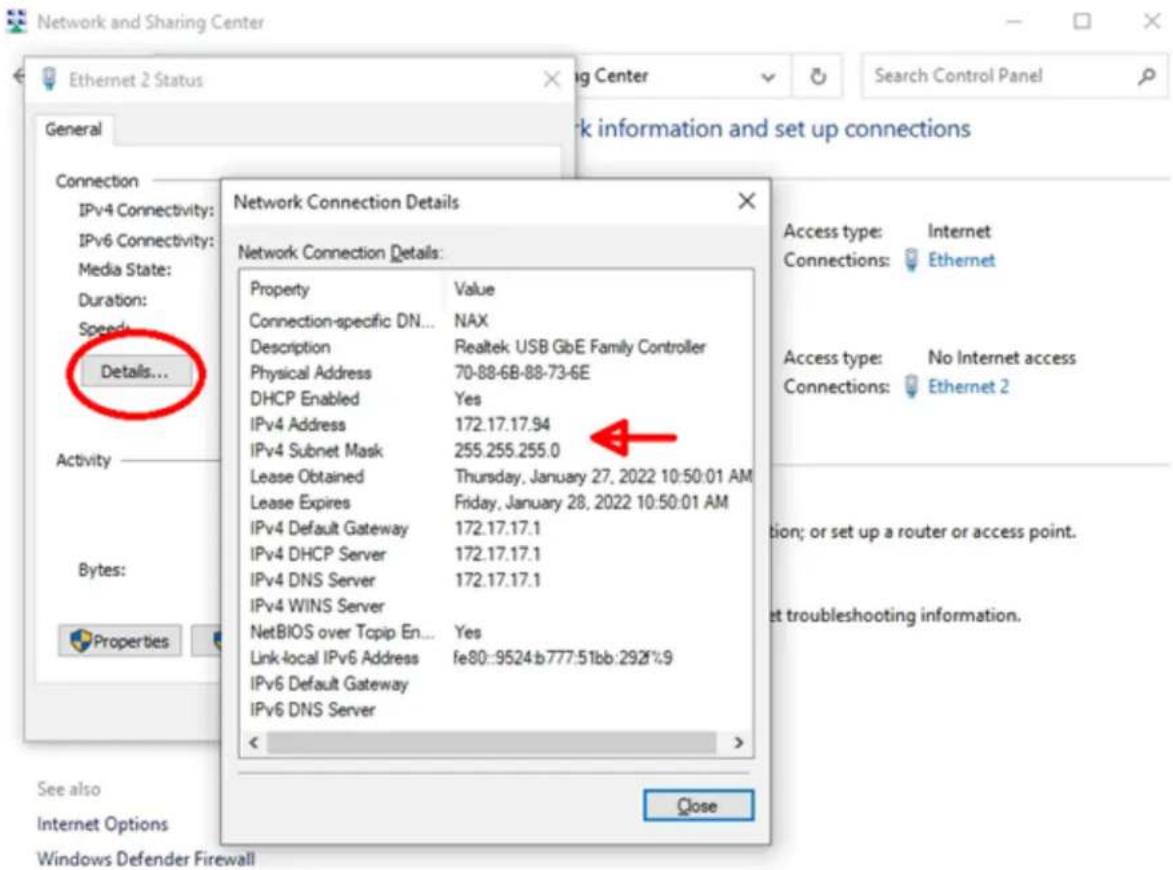
text_image
Network and Sharing Center Ethernet 2 Status General Connection IPv4 Connectivity: IPv6 Connectivity: Media State: Duration: Speeds... Details... Activity Bytes: Properties See also Internet Options Windows Defender Firewall Network Connection Details Network Connection Details: Property Value Connection-specific DN... NAX Description Realtek USB GbE Family Controller Physical Address 70-88-6B-88-73-6E DHCP Enabled Yes IPv4 Address 172.17.17.94 IPv4 Subnet Mask 255.255.255.0 Lease Obtained Thursday, January 27, 2022 10:50:01 AM Lease Expires Friday, January 28, 2022 10:50:01 AM IPv4 Default Gateway 172.17.17.1 IPv4 DHCP Server 172.17.17.1 IPv4 DNS Server 172.17.17.1 IPv4 WINS Server NetBIOS over Tcpip En... Yes Link-local IPv6 Address fe80::9524:b777:51bb:292%:9 IPv6 Default Gateway IPv6 DNS Server < Close Access type: Internet Connections: Ethernet Access type: No Internet access Connections: Ethernet 2 tion; or set up a router or access point. et troubleshooting information.Configure Shure® IntelliMix® Room to Use Ethernet 2
- On the UC-Engine, launch the IntelliMix Room by clicking its icon on the task bar.
- Click Network on the left panel.
a. Under Shure control, select Ethernet 2.
b. Under Dante® Audio network, select Ethernet 2.

text_image
Shure - IMX-RM-L4-S435DB9FB18E File View Help IMX-RM-L4-54... Mute all Use Designer for full configuration Download Settings General Network Version Licensing PC info Security Audio encryption Permissions Reset Shure control Select the network interface (NIC) used to access devices Ethernet (10.64.68.131) Ethernet 2 (172.17.17.94) Wi-Fi (0.0.0.0) @Dante Audio network Select the network interface (NIC) used to access audio Ethernet (10.64.68.131) Ethernet 2 (172.17.17.94) SNORE Type here to search Shure - IMX-RM-L4... 45°F Cloudy 11:07 AM 1/27/2022- Close IntelliMix Room and restart the UC-Engine.
Set up Shure IntelliMix Using Shure Designer
- Connect a PC that is running Shure Designer to the Ethernet 2 network.
- Open Shure Designer.
- Ensure that the UC-Engine running Shure Intellimix displays as an online device.
- Add the UC-Engine, Dante mics, and speakers to a room and make appropriate routes to complete the configuration.
ADPT-USB-ENET
The ADPT-USB-ENET provides a direct connection between a UC-ENGINE or UC-ENGINE-SD and a Crestron® control interface in a Crestron Flex system. The direct connection accelerates deployment, ensures reliability, and provides long-term service while eliminating network setup dependencies related to hardware and security requirements.
The ADPT-USB-ENET supports up to 100 Mbps transfer speed for reliable data transmission in a Crestron Flex system. LED indicators provide diagnostic information on the connection and data transfer.
Connect the USB connector to a USB port on a UC-ENGINE or UC-ENGINE-SD and connect the RJ-45 port to a LAN port on a Crestron control interface with a CAT5 (or better) Ethernet cable (sold separately).
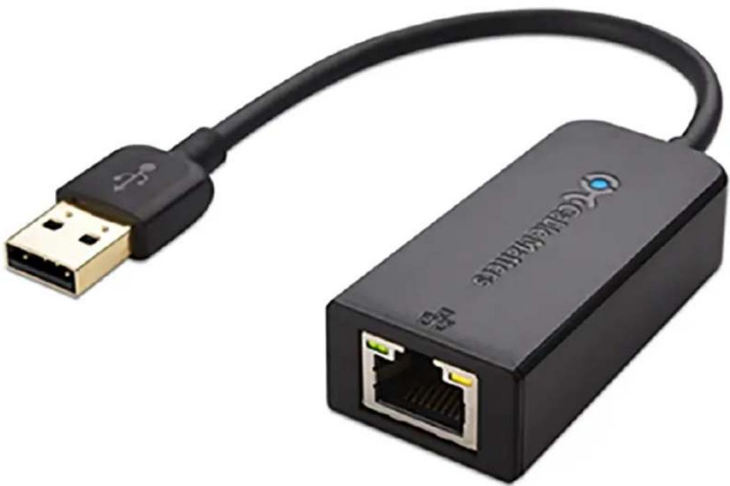
natural_image
Black USB network adapter with Ethernet port and USB cable (no text or symbols visible)CCS-UCA-MIC
The CCS-UCA-MIC is a low-profile extension microphone pod designed exclusively for use with a Crestron Flex Tabletop Conference System. Up to two mic pods may be connected to a single conference device to extend its pickup range to cover large tables.
Optionally, two microphone pods may be daisy-chained, or connected to the mic pod ports on the rear of the conference device, using the cables provided with each microphone pod.
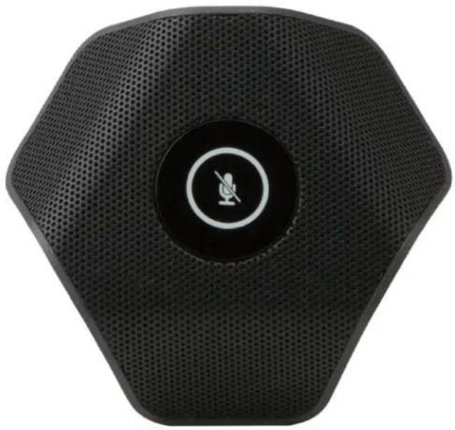
natural_image
Black hexagonal electronic device with a circular button and a microphone symbol (no text or labels visible)Connecting CCS-UCA-MIC
In the Box
Qty. Description
1 CCS-UCA-MIC, Microphone pod (6508084)
1 Cable, RJ-9 - RJ-9, 12 ft (3.7 m) (2048239)
Connections
The mic pod is connected to the conference device. While a single mic pod must be connected using the Direct Connection on page 525 only, the conference device supports up to two mic pods, which can be connected using either Direct Connection on page 525 or Daisy-chain Connection on page 526.
Direct Connection
To connect up to two mic pods to the conference device, make system connections as shown in the following illustration:

Microphone Pod
12 ft cable
12 ft cable (not included)

text_image
Conference Device USB/ACC 24V USB 2.5A LAN HDMI OUT HDMI IN 1+ HDC POD 2 USB/CAM Power Supply Microphone Pod Microphone Pod (not included)Daisy-chain Connection
To connect two mic pods to the conference device, make system connections as shown in the following illustration:
NOTE: The conference device supports up to two mic pods connected using either Direct Connection on page 525 or Daisy-chain Connection on page 526.

Microphone Pod
12 ft cable
12 ft cable (not included)

text_image
Conference Device IR COM USB B LAN AUX NDMI OUT NDMI IN 1. MIC POD - 2 USB/ACC 24V EYES 2.5A USB/CAM Power Supply Microphone Pod (not included) Microphone PodOperation
To operate the mic pod after making the system connections:
-
Turn on the conference device to supply power to the mic pod.
-
On the top of the mic pod, tap the button with the bi-color status LED to mute or unmute the n pod.
The status LED lights red to indicate that the mic pod is muted and lights green when unmuted.
NOTE: Tapping the mic pod button will also mute or unmute the conference device and second connected mic pod (not included).
CCS-UCA-SMK
The CCS-UCA-SMK is a low-profile swivel mount accessory for the Crestron Mercury® Tabletop Conference System (model CCS-UC-1). It provides a means for permanently mounting the device to a tabletop surface while retaining the ability to rotate it for optimal positioning.
The swivel range can be customized using optional limit screws, with a maximum of approximately 180-degree rotation allowed. The swivel mount may be installed on any flat, level surface with a thickness of 1 inch (25 mm) minimum to 1-3/8 inch (35 mm) maximum. Wiring is routed through the center of the swivel mount, passing beneath the mounting surface for a completely hidden appearance.

natural_image
Exterior view of a black industrial sensor or antenna device with mounting base and threaded connector (no text or symbols visible)Installing CCS-UCA-SMK
To secure the Crestron Mercury® tabletop conference system on a table using the CCS-UCA-SMK swivel mount kit, refer to DO Guide for: CCS-UCA-SMK.
UC-CAMA-ADPT-ENET-USB
The UC-CAMA-ADPT-ENET-USB is a plug and play USB adapter used to connect the UC-CAM-L1 to a meeting room device. It supports easy camera installation by using a single Ethernet cable to enable flexible BYOD setups.
With its plug and play format, the adapter enables the camera to perform as a USB Video Class (UVC) device that is compatible with various software applications such as Microsoft Teams ^® , Zoom ^® , and Google Meet ^™ .

natural_image
Black rectangular electronic device with a small port and two circular ports, no visible text or symbols.Key Features
- Supports the Huddly® L1™ AI collaboration camera in flexible BYOD setups
• USB plug and play support
• USB Video Class (UVC) support - PoE output to power a connected camera
Specifications
Connectivity
Connector RJ-45
USB USB Type-C® port
Power Requires external 5V 3A power using the included external AC/DC 5V 4A power adapter
Construction
Material Aluminum
Dimensions
Height 1.1 in. (27 mm)
Width 3.2 in. (82 mm)
Depth 3.2 in. (82 mm)
Weight
0.4 lb (0.2 Kg)
UCA-PWE-UC-2/UC-P8/P10
The UCA-PWE-UC-2/UC-P8/P10 is a Power over Ethernet (PoE) power source for optional use with Crestron® UC-2, UC-P8, and UC-P10 series devices in environments where a PoE infrastructure is not available.
The UCA-PWE-UC-2/UC-P8/P10 can be mounted at any convenient location up to 100 meters (328 feet) from the device.
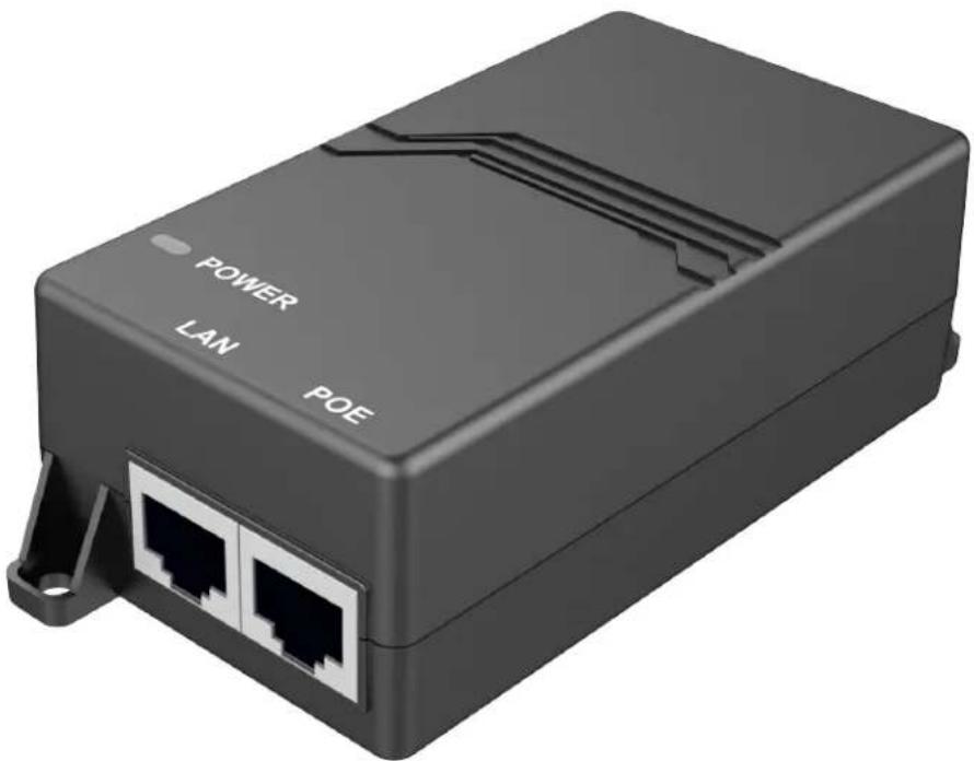
natural_image
Black rectangular device with two Ethernet ports and a power button labeled 'POWER LAN POE' (no additional text or symbols visible)Connecting UCA-PWE-UC-2/UC-P8/P10
In the Box
Qty. Description
1 PoE injector (Output rating: 500 mA maximum @ 48VDC nominal) (6511770)
Connections
Make device connections as shown below.

flowchart
graph TD
    A["PoE Injector"] -->|POWER| B["UC-P8/P10 Series Devices"]
    A -->|LAN| C["UC-2 Series Devices"]
    B --> D["Power Supply"]
    C --> E["Power Supply"]
    style A fill:#f9f,stroke:#333
    style B fill:#ccf,stroke:#333
    style C fill:#cfc,stroke:#333
    style D fill:#ffc,stroke:#333
    style E fill:#fcc,stroke:#333
NOTES:
- The UCA-PWE-UC-2/UC-P8/P10 is for use with UC-2, UC-P8, and UC-P10 series devices only. Do not use it to power other PoE devices.
- Only one PoE enabled device at a time can be powered with the UCA-PWE-UC-2/UC-P8/P10.
UCA-RMK-1U
The Crestron® UCA-RMK-1U is a rack mount kit that allows a UC Engine bracket assembly to be installed into a 19 in. EIA equipment rack.
The UCA-RMK-1U occupies 2 units of rack space when attached to the UC Engine bracket assembly.

natural_image
Two black metal structural components with mounting flanges and a separate open panel showing internal wiring and labels (no readable text or symbols)Installing UCA-RMK-1U
In the Box
| Qty. Description |
| 1 Rack Ear, Left (2057927) |
| 1 Rack Ear, Right (2057928) |
| 4 Washer (2007671) |
| 4 Nut (2004887) |
Installation
To install the UC Engine bracket assembly into a 19 in. EIA equipment rack using the rack ears:
- Place the left and right rack ears on a flat surface.
-
Position the four threaded studs of the left and right rack ears through the four holes in the UC Engine Bracket Assembly, as shown in Figure A.
-
Secure the rack ears to the bracket assembly using the included four washers and four nuts.
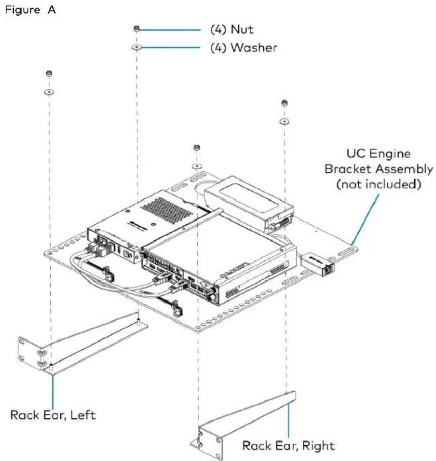
text_image
Figure A (4) Nut (4) Washer UC Engine Bracket Assembly (not included) Rack Ear, Left Rack Ear, Right- Mount the assembled UC Engine Bracket Assembly into the rack using four rack mounting screws (not included), as shown in Figure B.
Figure B
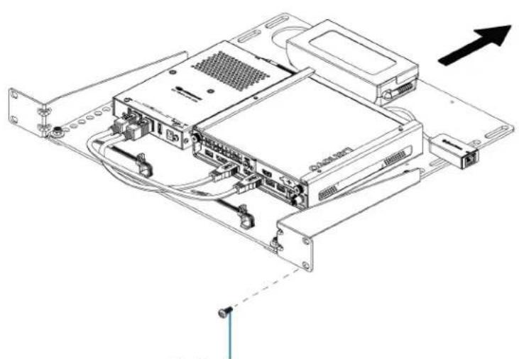
natural_image
Technical line drawing of an electronic device chassis with connectors and wiring (no text or symbols)(4) Screws (not included)
UCA-SMK-UC2 and UCA-SMKR-UC2-3
The Crestron UCA-SMK-UC2 and UCA-SMKR-UC2-3 are swivel mount accessories for Crestron Flex Tabletop Small Room Conference Systems. They enable tabletop conference device mounting with up to 170° rotation for optimal positioning. The UCA-SMK-UC2 is designed for mounting the UC-MM30 series tabletop conference device. The UCA-SMKR-UC2-3 is designed for the UC-MMX30 series tabletop conference device and has the following additional features:
- Retracts the installed USB-A to Micro USB-B cable, HDMI cable, and USB-C cable.
- Above the table, the USB-A, HDMI, and USB-C cables support Bring Your Own Device (BYOD) connectivity for the tabletop conference device.
- Below the table, the Micro USB-B, HDMI, and USB-C cables connect to the UC-PR which is included with the UC-MMX30.
UCA-SMK-UC2
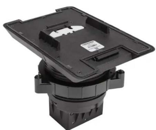
natural_image
Black plastic mechanical component with mounting base and mounting holes (no visible text or symbols)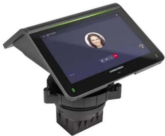
natural_image
Exterior view of a modern office building (no signage)UCA-SMKR-UC2-3
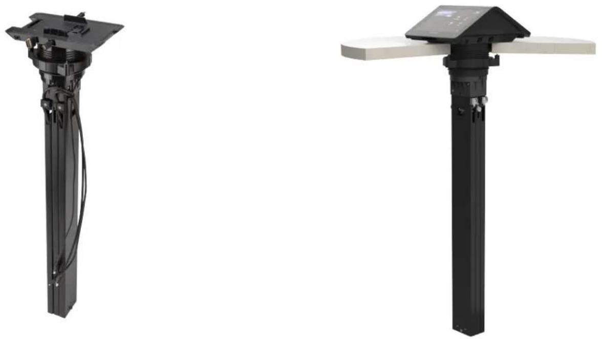
Installing UCA-SMK-UC2 and UCA-SMKR-UC2-3
The UCA-SMK-UC2 and UCA-SMKR-UC2-3 have similar installation instructions. For simplicity within this guide, the term "swivel mount accessory" is used except where otherwise noted.
In the Box
Qty. Description
1 UCA-SMK-UC2 or UCA-SMKR-UC2-3 Swivel Mount Accessory (6511567 or 6511362)
Additional Items
1 Locking ring with screws (4519116)
1 Cutout Template (4532125)
1 Allen wrench, 3/32 in. (2036829)
UCA-SMK-UC2
Swivel Mount

natural_image
Technical illustration of a mechanical component with coiled spring and housing (no text or symbols)UCA-SMKR-UC2-3 Swivel Mount Cable Retractor
Cable retractor end of the USB-A to Micro USB-B, HDMI, and USB-C cables. Connect to BYOD device.
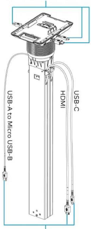
text_image
USB-A to Micro USB-B HDMI USB-CConnect to UC-PR (included with UC-MMX30).
Install the Swivel Mount Accessory
Install the swivel mount accessory on any flat, level surface with a thickness of 1/2 in. (13 mm) minimum to 1-1/4 in. (32 mm) maximum. The LAN and USB cables for the UC-MM30 or UC-MMX30 tabletop conference device route through the cable cover of the swivel mount accessory, passing beneath the mounting surface for a completely hidden appearance. Refer to the Mount the Swivel Mount Accessory on page 540 section for more information.
UCA-SMK-UC2
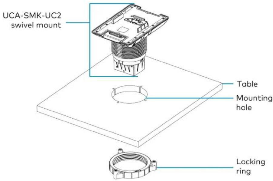
text_image
UCA-SMK-UC2 swivel mount Table Mounting hole Locking ringUCA-SMKR-UC2-3
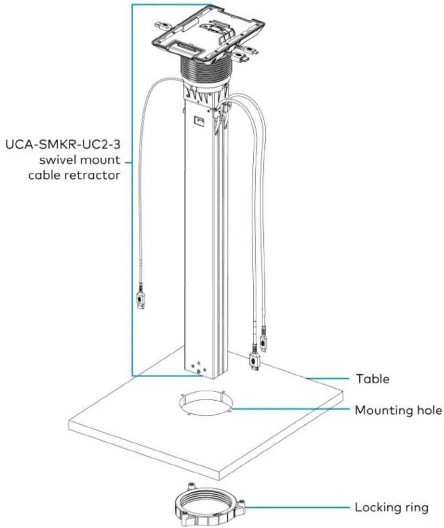
text_image
UCA-SMKR-UC2-3 swivel mount cable retractor Table Mounting hole Locking ringMount the Swivel Mount Accessory
When determining the mounting location, consider where users will be seated and their proximity to the swivel mount accessory and the tabletop conferencing system. The mounting location must accommodate a 170° swivel range. Additionally, the UCA-SMKR-UC2-3 requires a 27.42 in. (696 mm) clearance for the cable retractor body below the table.
A 4 in. hole saw, a jigsaw, a 3/32 in. Allen wrench (included), and the cutout template (included) are required to mount the swivel mount accessory.
- Secure the cutout template to the mounting location. The notch on the template and the swivel mount accessory indicates the front of the swivel mount accessory.
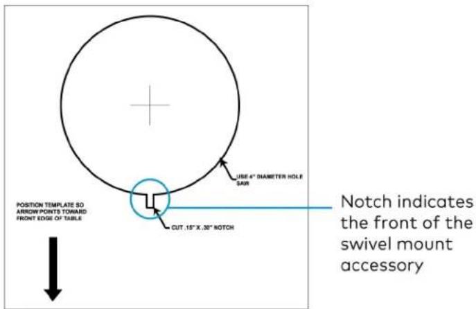
text_image
POSITION TEMPLATE SO ARROW POINTS TOWAID FRONT EDGE OF TABLE USE 4" DIAMETER HOLE SAW CUT .15" X .30" NOTCH Notch indicates the front of the swivel mount accessory-
Use a hole saw (not included) to drill a 4 in. hole in the table.
-
Use a jig saw (not included) to cut the front notch.
-
Insert the body of the swivel mount accessory into the mounting hole. Match the notch on the front of the swivel mount accessory with the notch in the table.
-
Beneath the table, twist the included locking ring onto the body of the swivel mount accessory.
NOTES:
• Make sure the surface of the locking ring labeled TOP faces the bottom of the table.
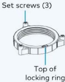
text_image
Set screws (3) Top of locking ring- Leave a 1/8 in. (4 mm) gap between the locking ring and the bottom of the table.
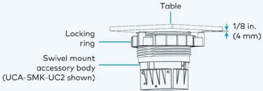
text_image
Table 1/8 in. (4 mm) Locking ring Swivel mount accessory body (UCA-SMK-UC2 shown)- Secure the locking ring to the bottom of the table. Use a 3/32 in. Allen wrench (included) to tighten the three set screws included with the locking ring.
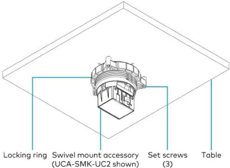
text_image
Locking ring Swivel mount accessory (UCA-SMK-UC2 shown) Set screws (3) TableConnect and Dock the Tabletop Conference Device
Make the USB and LAN connections to the tabletop conference device before docking it to the swivel mount accessory, as the device blocks access to the cable cover pass-through holes. Once docked, continue making connections to the tabletop conference device.
To make the USB and LAN connections to the tabletop conference device:
- Route the USB and LAN cables along the outside of the swivel mount body through cable cover pass-through holes.
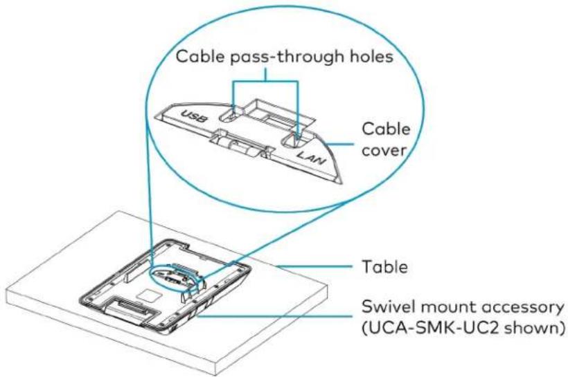
text_image
Cable pass-through holes USB LAN Cable cover Table Swivel mount accessory (UCA-SMK-UC2 shown)-
Connect the USB and LAN cables to the tabletop conference device.
-
Use the optional cable clamp to hold the USB and LAN cables in place.

text_image
Locking ring Swivel mount accessory (UCA-SMK-UC2 shown) Cable clamp USB and LAN cablesDock the Tabletop Conference Device
Dock the tabletop conference device to the swivel mount accessory.
- Position the tabletop conference device above the swivel mount surface.
- Slide the tabletop conference device onto the swivel mount accessory, moving the device back to front. The device must engage with the latch at the back of the swivel mount accessory.
- Gently press the tabletop conference device to engage it with the swivel mount accessory.
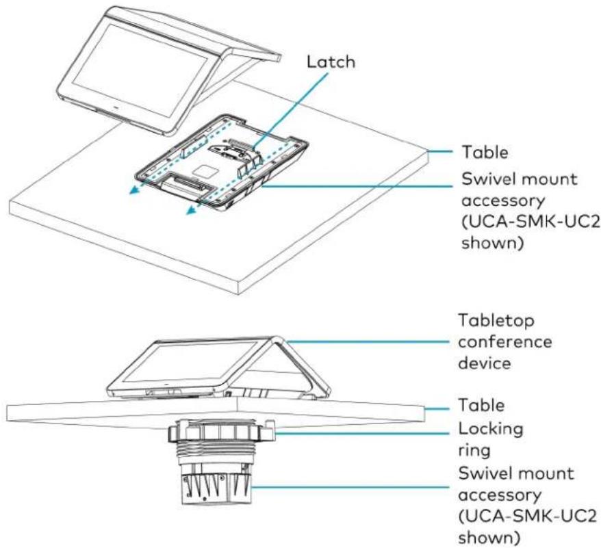
text_image
Latch Table Swivel mount accessory (UCA-SMK-UC2 shown) Tabletop conference device Table Locking ring Swivel mount accessory (UCA-SMK-UC2 shown)Continue Connecting the Tabletop Device
Connect the USB and LAN cables to the source devices.
For the UCA-SMKR-UC2-3, connect the BYOD and UC-PR connections.
UCA-SMKR-UC2-3

text_image
Cable retractor end of the USB-A to Micro USB-B, HDMI, and USB-C cables. Connect to BYOD device. Tabletop device USB and LAN cable pass-through holes Table USB-A to Micro USB-B HDMI USB-C Connect tp UC-PR (included with UC-MMX30)Lock the Tabletop Conference Device
To lock the tabletop conference device to the swivel mount accessory, locate the release button and the security screw. Use a 3/23 in. Allen wrench (included) to tighten the security screw. Ten clockwise revolutions locks the release button.
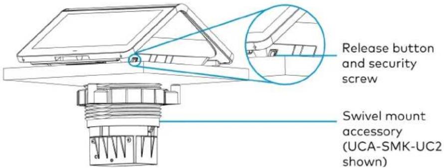
text_image
Release button and security screw Swivel mount accessory (UCA-SMK-UC2 shown)Unlock the Tabletop Conference Device
If the tabletop conference device is locked to the swivel mount accessory, locate the security screw and use a 3/32 in. Allen wrench to release the security screw. Ten counterclockwise revolutions unlocks the security screw. Press the release button to disengage the latch on the swivel mount accessory, and slide the tabletop conference device off of the swivel mount accessory.
Crestron Flex Products (sold separately)
This section lists Crestron Flex products that are available to purchase separately. For pricing, detailed features, specifications, and other details, refer to the product pages of the selected Crestron Flex products.
- UC-AUDIO-HUB
• UC-AUDIO-POD
UC-CAM-L1
• CCS-CAM-USB-F-400 - Mounting CCS-CAM-USB-F-400
• UC-P8 and UC-P10 Series Displays for Microsoft Teams Software
• UC-P8 and UC-P10 Series Desk Phones for Microsoft Teams Software - UC-SB1
UC-SB1-CAM
• UC-SB-P50 and UC-SB-P50-INDIA
UC-AUDIO-HUB
The Crestron Flex UC-AUDIO-HUB is a wireless transceiver and auto mixer that connects with up to four paired Crestron Flex UC-AUDIO-POD devices through the Digital Enhanced Cordless Telecommunications (DECT™) technology. The hub receives audio from the pods' microphones, auto-mixes the audio, and transfers it to a UC Engine through a USB-C connection. The hub also distributes audio to all paired pods after receiving the audio from the UC Engine.
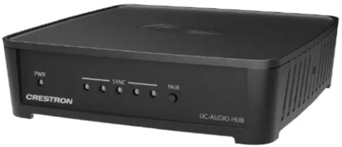
text_image
PWR SYNC PAIR CRESTRON UC-AUDIO-HUBInstalling UC-AUDIO-HUB
The hub can be mounted on a wall, DIN rail, or placed on any flat surface. For details, refer to Product Manual: UC-AUDIO-POD and UC-AUDIO-HUB.
UC-AUDIO-POD
The Crestron Flex UC-AUDIO-POD is a wireless tabletop conferencing device with a speaker and four microphones that is ideal for small to large rooms. The pod wirelessly connects and transfers audio to and from a paired Crestron Flex UC-AUDIO-HUB. The connected hub receives and sends audio to a UC Engine through a USB-C connection. Up to four pods can connect with the hub, providing omnidirectional sound in large or medium conference rooms and multi-purpose meeting spaces. The pod can be placed anywhere within a room or mounted on a table, depending upon the size and shape of the meeting space.
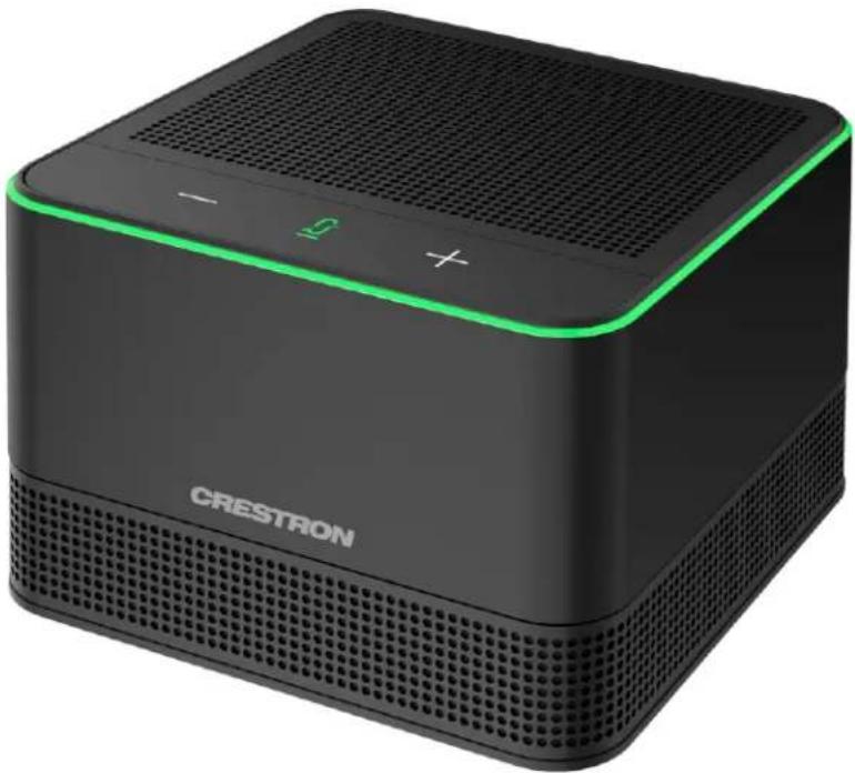
natural_image
Black CRESTRON portable sound streaming device with green accent and grille (no visible text or symbols on device body)Installing UC-AUDIO-POD
The UC-AUDIO-POD can be placed on any flat surface or secured on a table using the UC-AUDIO-POD-TTMK tabletop mounting kit (sold separately). For details, refer to Product Manual: UC-AUDIO-POD and UC-AUDIO-HUB.
UC-CAM-L1
The UC-CAM-L1 is an intelligent, high-definition collaboration camera compatible with Crestron Flex large meeting room videoconferencing solutions. It features a wide-angle 103° diagonal field of view to capture an entire conference room with Full HD 1080p resolution. High precision aspherical optics, a 20.30 MP 1 in. CMOS sensor, portrait lighting, and advanced video processing ensure an immersive, crystal clear video image free from light or noise artifacts or optical aberrations. The camera has no moving parts, ensuring quiet operation, reliability, and accuracy while adjusting Pan, Tilt and Zoom functions.

natural_image
Black and white photo of a digital camera with lens and stand (no text or symbols visible)Note:
- The UC-CAM-L1 with network adapter requires driver installation on the connected laptop. A USB plug-and-play adapter, UC-CAMA-ADPT-ENET-USB, can be purchased separately to avoid driver installation.
Installing UC-CAM-L1
Mount the camera according to its included documentation.
CCS-CAM-USB-F-400
Compact in size, yet tremendous on performance, the Huddly IQ™ camera (sold as model CCS-CAM-USB-F-400) features an ultra wide-angle 150° diagonal field of view to capture an entire conference room with Full HD 1080p resolution. High precision aspherical optics, a 12 MP CMOS sensor, and advanced video processing ensure an immersive, crystal clear video image free from light or noise artifacts or optical aberrations. The camera has no moving parts, ensuring quiet operation, reliability, and accuracy.
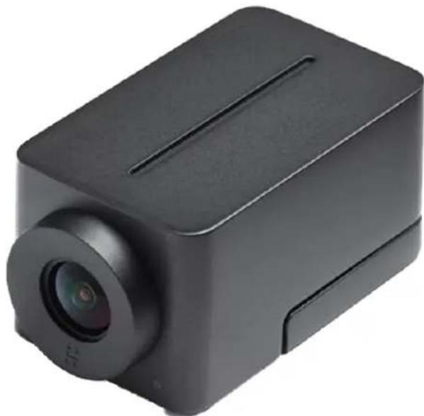
natural_image
Black rectangular device with a circular lens and rectangular body, no visible text or symbolsMounting CCS-CAM-USB-F-400
Mount the camera using the included UC-CAM-WMK wall mount kit.
The wall mount kit provides secure mounting options for CCS-CAM-USB-F-400. It comes with two mounting brackets and mounting hardware that allow for a variety of mounting locations.
In the Box (UC-CAM-WMK)
Qty. Description
| 1 UC-CAM-WMK, Wall Mount Kit for CCS-CAM-USB-F-400 (6510998) | |
| Additional Items | |
| 2 Anchor, Wall, Plastic, #6 x 1-1/4 in. (2043585) | |
| 1 Bracket, Camera, 2.00 in. to 3.50 in. (51 mm to 89 mm) (2053562) | |
| 1 Bracket, Camera, 3.50 in. to 5.00 in. (89 mm to 127 mm) (2053561) | |
| 1 Screw, 1/4-20, 5/16 in., Flat Head, Phillips (2040253) | |
| 2 Screw, 6-AB x 1 in., Pan Head, Phillips, Black (2053606) | |
| 2 Tie Wrap, Releasable (2005430) | |
Installing the Wall Mount Kit
Select an appropriate mounting location and install the bracket.
Choose a Location
For optimal viewing results, the bracket should be mounted in a location that places the camera above the plane of the room's conference table.
Choose a Bracket
The wall mount kit comes with two brackets to accommodate a variety of mounting locations. The smaller bracket allows the back of the camera to be placed 2.00 in. to 3.50 in. (51 mm to 89 mm) off wall while the larger bracket allows the back of the camera to be placed 3.50 in. to 5.00 in. (89 mm to 127 mm) off the wall.
NOTES:
• The camera can be mounted on top of or under the bracket.
- When using the CCS-CAM-USB-F-100, the smaller bracket allows the back of the camera to be placed 2.25 in. to 3.00 in. (57 mm to 76 mm) off the wall while the larger bracket allows the back of the camera to be placed 3.75 in. to 4.55 in. (95 mm to 116 mm) off the wall.
Small bracket, CCS-CAM-USB-F-400 camera shown

text_image
Camera 3.50 in. (89 mm) 2.00 in. (51 mm) Screw, 6-AB x 1 in., Pan Head (x2) Bracket 3.80 in. (97 mm) 1.50 in. (38 mm) 4.61 in. (117 mm) 6.35 in. (162 mm) USB PortLarge bracket, CCS-CAM-USB-F-400 camera shown
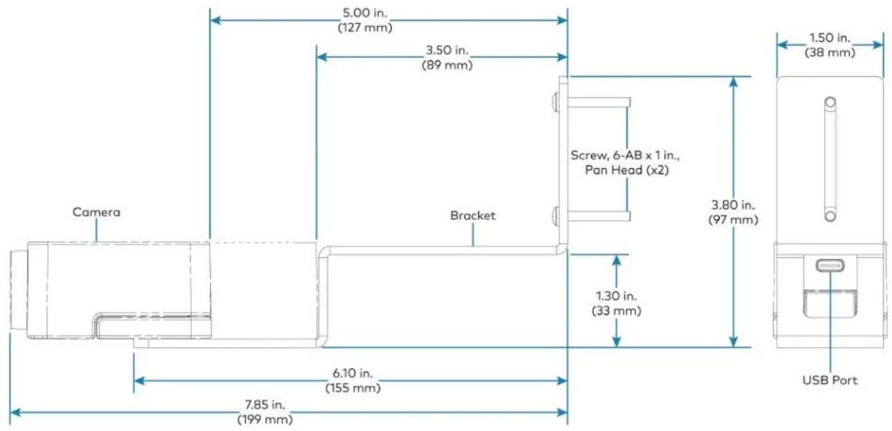
text_image
5.00 in. (127 mm) 3.50 in. (89 mm) Camera Bracket Screw, 6-AB x 1 in., Pan Head (x2) 3.80 in. (97 mm) 1.50 in. (38 mm) 1.30 in. (33 mm) 6.10 in. (155 mm) USB Port 7.85 in. (199 mm)Secure the Bracket
Secure the bracket to the mounting surface with the included 6-AB x 1 in. pan head screws. Use the included anchors for mounting locations where a stud cannot be found.
Secure the bracket (large bracket shown)

text_image
Screw, 6-AB x 1 in., Pan Head (x2) BracketAttach the Camera
Attach the camera to the bracket with the included 1/4-20, 5/16 in. flat head screw. The camera can be positioned forward and back along the bracket.
Attach the camera (large bracket with CCS-CAM-USB-F-400 camera shown)
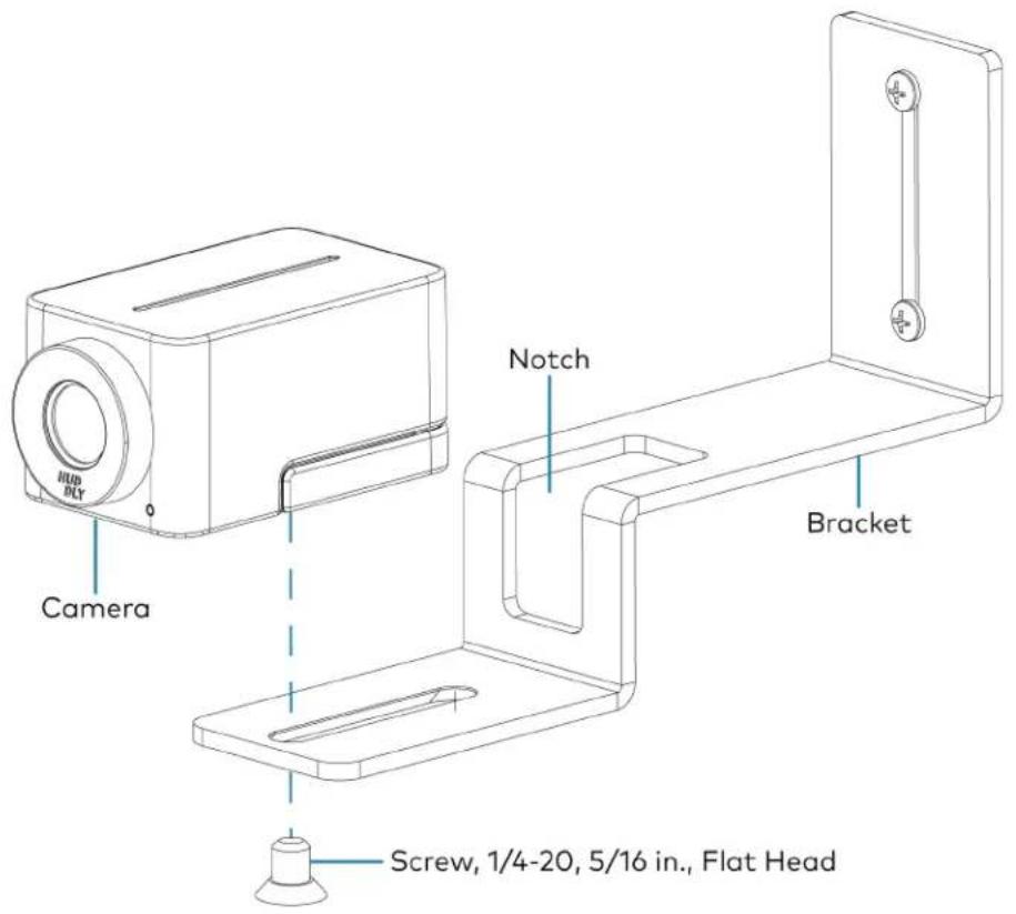
text_image
HUB BUY Camera Notch Bracket Screw, 1/4-20, 5/16 in., Flat HeadConnect
Thread the cable that is included with the camera through the notch in the bracket and connect it to the camera's USB port and a USB device. Use the included tie wraps to secure excess cable.
NOTE: On the CCS-CAM-USB-F-100, the cable is attached to the camera.
UC-P8 and UC-P10 Series Displays for Microsoft Teams Software
The Crestron Flex UC-P8 and UC-P10 series display provides a premium video collaboration solution for use with the Microsoft Teams® display intelligent communications platform. It offers Full HD quality video and audio calling, capability to view and zoom the shared content, and full-duplex hands-free speakerphone capability in an elegant desktop design. It features a large 10 in. color touch screen display, built-in Full HD camera with privacy shutter, and wired or Bluetooth® enabled headset support. Each display can be synced with a Microsoft Teams® account, with contacts, schedules, voicemails, and other preference settings appearing on the display's touch screen.
UC-P10-TD(-I) UC-P8-TD(-I)
Installing UC-P8 and UC-P10 Series Display
The UC-P8 and UC-P10 Series Display can be placed on any flat surface or mounted on a wall using the UC-AUDIO-POD-TTMK tabletop mounting kit (sold separately). For details, refer to:
• UC-P8 Series Displays installation and connections: Quick Start: UC-P8-TD and UC-P8-TD-I
• UC-P10 Series Displays installation and connections: Quick Start: UC-P0-TD and UC-P10-TD-I
Configuring UC-P8 and UC-P10 Series Display
To configure the the UC-P8 and UC-P10 Series Display, refer to Product Manual: Crestron Flex UC-P8 and UC-P10 Series Desk Phones and Displays for Microsoft Teams Software.
UC-P8 and UC-P10 Series Desk Phones Microsoft Teams Software
The Crestron Flex UC-P8 and UC-P10 series audio and video desk phones provide premium video collaboration solution for use with the Microsoft Teams intelligent communications platform. It offers Full HD quality video and audio calling, capability to view and zoom the shared content, and full-duplex hands-free speakerphone capability in an elegant desktop design. It features a large 10 in. color touch screen display, built-in Full HD camera with privacy shutter, hearing aid compatible handset, and wired or Bluetooth® enabled headset support. Each phone can be synced with a Microsoft Teams account, with contacts, schedules, voicemails, and other preference settings appearing on the phone's touch screen.
UC-P10 Series UC-P8 Series

natural_image
Two black digital video call devices with face monitors displaying video content (no visible text or symbols on screens)Installing UC-P8 and UC-P10 Series Desk Phones
The UC-P8 and UC-P10 series audio and video desk phones can be placed on any flat surface or mounted on a wall using the UC-AUDIO-POD-TTMK tabletop mounting kit (sold separately). For details, refer to:
- UC-P8-T-HS(-I) series desk phones installation and connections: Quick Start: UC-P8-T-HS, and UC-P8-T-HS-I
- UC-P8-T-C-HS(-I) series desk phones installation and connections: Quick Start: UC-P8-T-C-HS, and UC-P8-T-C-HS-I
- UC-P10-T-HS(-I) series desk phones installation and connections: Quick Start: UC-P10-T-C-HS and UC-P10-T-C-HS-I
- UC-P10-T-C-HS(-I) series desk phones installation and connections: Quick Start: UC-P10-T-C-HS and UC-P10-T-C-HS-I
Configuring UC-P8 and UC-P10 Series Desk Phones
To configure the the UC-P8 and UC-P10 series desk phones, refer to Product Manual: Crestron Flex UC-P8 and UC-P10 Series Desk Phones and Displays for Microsoft Teams Software.
UC-SB1
The Crestron UC Video Conference Smart Soundbar (UC-SB1) is a front-of-room device that eliminates the need to install additional microphones or speakers in a conference space. Mounted on the wall or placed on a credenza beneath the room display, the smart soundbar looks great and sounds even better in a small to medium-sized meeting space.
High-powered stereo speakers, adaptive beamforming microphone, and advanced digital signal processing deliver exceptional full-duplex speakerphone performance with highly intelligible, echo-free voice clarity. A USB camera can be connected via a USB 3.0 port on the rear panel.
Mounting UC-SB1
In the Box
Qty. Description
| 1 UC-SB1-CAM, UC Video Conference Smart Soundbar & Camera (6511280) |
| Additional Items |
| 4 Anchor, Drywall, Plastic, 3/8 in. x 1/2 in. (2052565) |
| 1 Cable, USB 3.0, A - B, 6 ft (1.83 m) (2053077) |
| 2 Foot, 2.3 in. x 0.96 in. x 0.15 in., Rubber (2052169) |
| 1 Key, Anchor (4529654) |
| 1 Power Cord, 5 ft 10 in. (1.78 m) (2042043) |
| 1 Power Pack, 24 VDC, 2.5 A, 100-240 VAC (2045873) |
| 4 Screw, 8-AB x 1-1/2 in., Pan Head, Combo (2052567) |
| 1 Template, Overlay (4529513) |
The soundbar can be placed on a flat surface or mounted on a wall. The soundbar has the following dimensions.

text_image
3.90 in. (99 mm) 43.60 in. (1107 mm) 4.57 in. (116 mm)Place on a Flat Surface
If the soundbar is to be placed on a flat surface, attach the included rubber feet to the bottom of the soundbar as shown.
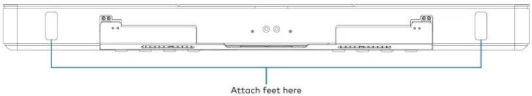
text_image
Attach feet hereMount on a Wall
The soundbar includes anchors that are suitable for mounting it on sheetrock walls up to 1/2 in. (13 mm thickness. Masonry and other materials may require additional installer-supplied mounting hardware.
NOTE: When mounting on a wall beneath a display device, leave 3/4 in. (minimum) clearance above the top of the soundbar. Use the included template to allow for sufficient clearance between the soundbar and display device.
The following tools are required to mount the soundbar:
• Drywall saw (not included)
- Drill with 5/16 in. bit (not included)
A template is included to provide drill hole locations for the included mounting hardware.
- Attach the template to the desired mounting location with the template's center reference line at the center of the desired location.
NOTE: Use the center reference hole of the template as a guide to attach the template.

text_image
Drill one of these two holes Cutout for soundbar cables Center reference hole Drill one of these two holes SOUNDBAR ACTUAL HEIGHT MIN. DISTANCE FROM BOTTOM OF DISPLAY CENTER REFERENCE HOLE TO HOLD TEMPLATE TEMPORARY TEMPLATE - 40161 FOR UC-SB1 TOTAL OF 4 SCREWS MUST BE USED (2 ON EACH SIDE, 1 PER ROW) TO SECURE THE SOUNDBAR TO THE WALL Drill one of these two holes Center reference line Drill one of these two holes- Drill two pilot holes on each side of the center reference line as shown in the previous diagram. Each side should have one pilot hole drilled in each row of the template.
- Use a drywall saw to make a cutout in the wall for the soundbar cables. The cutout in the center of the template provides adequate access for all of the required cabling.
-
Install the four included anchors and screws into the drilled pilot holes.
-
Place the soundbar face down, and pivot the wall bracket away from the soundbar.

text_image
Wall bracket Soundbar- Place the wall bracket over the screws, and hand tighten the screws until the wall bracket is secured to the wall.
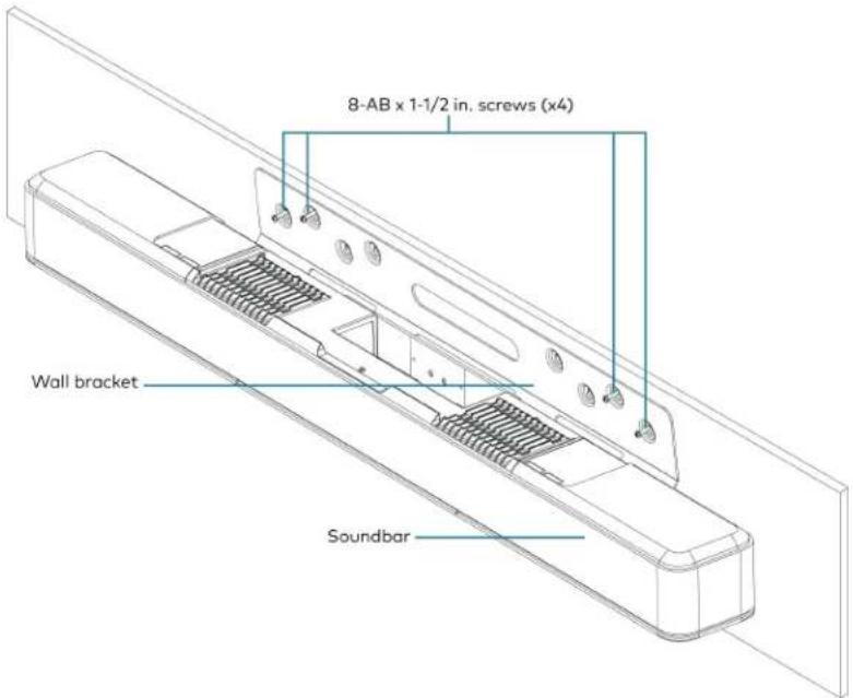
text_image
8-AB x 1-1/2 in. screws (x4) Wall bracket Soundbar- Route the cables through the cable cutout.
NOTE: The included power pack's cord is typically routed from the wall opening, through the cable cutout, to the soundbar.
Connect
Make the necessary connections as called out in the following diagram. Connect power last. Once all connections are made, pivot the soundbar up to the wall bracket until the soundbar locks into place.

text_image
PC Audio and video to PC CAMERA From USB camera 24 V, 2.5 A From included power pack AUDIO IN and OUT Line-level audio input and output- PC: Connect the included USB cable to the PC port and to a USB port on the computer. For optimal results, use a USB 3.0 connection.
• CAMERA: Connect a USB camera (sold separately) to the CAMERA port.
• 24 V. 2.5 A: Connect the power pack to the 24 V. 2.5 A power input and to an AC power out
- AUDIO IN and AUDIO OUT: The soundbar provides unbalanced, stereo, analog input and output jacks (3.5 mm TRS mini-phone). The AUDIO IN port accommodates an optional line-level audio source which feeds to the internal amplifier and speakers without a volume control or other signal processing. The AUDIO OUT port provides a line-level signal for an optional assistive listening system and carries the same audio signal as the soundbar speakers.
Operation
Status
The front panel status bar illuminates to provide operational information.
- A green status bar indicates the volume level. Raising the volume increases the status bar's illumination. Lowering the volume decreases the status bar's illumination. When the volume = "O", the status bar is unlit.

natural_image
Pure diagram of a grid-patterned structure with no text, numbers, or symbols- Muting the microphone and speaker turns the two outer segments of the status bar red.
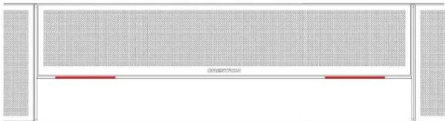
natural_image
Pure diagram of a rectangular structure with grid pattern and two red horizontal bars at the bottom (no text or symbols)- Muting the microphone turns the center of the status bar red.
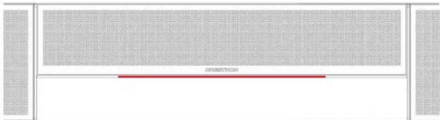
text_image
OPPSTROMSystem Control
The soundbar can be used in a BYOD scenario where the soundbar is connected to an end-user's PC over USB. The soundbar will pass bidirectional (mic and speaker) audio and camera (if a camera is connected) across a single USB connection.
UC-SB1-CAM
The Crestron UC Video Conference Smart Soundbar & Camera (UC-SB1-CAM) is a front-of-room device that eliminates the need to install additional microphones, speakers, or cameras in a conference space. Mounted on the wall or placed on a credenza beneath the room display(s), the smart soundbar looks great and sounds even better in a small to medium-sized meeting space.
High-powered stereo speakers, adaptive beamforming microphone, and advanced digital signal processing deliver exceptional full-duplex speakerphone performance with highly intelligible, echo-free voice clarity. A perfect view of the room is achieved through the built-in conferencing camera featuring HD 1080p video resolution, ultra-wide 150° diagonal field of view, and Genius Framing digital autozoom.
Mounting UC-SB1-CAM
In the Box
Qty. Description
| 1 UC-SB1-CAM, UC Video Conference Smart Soundbar & Camera (6511281) |
| Additional Items |
| 4 Anchor, Drywall, Plastic, 3/8 in. x 1/2 in. (2052565) |
| 1 Cable, USB 3.0, A - B, 6 ft (1.83 m) (2053077) |
| 2 Foot, 2.3 in. x 0.96 in. x 0.15 in., Rubber (2052169) |
| 1 Key, Anchor (4529654) |
| 1 Power Cord, 5 ft 10 in. (1.78 m) (2042043) |
| 1 Power Pack, 24 VDC, 2.5 A, 100-240 VAC (2045873) |
| 4 Screw, 8-AB x 1-1/2 in., Pan Head, Combo (2052567) |
| 1 Template, Overlay (4529513) |
The soundbar can be placed on a flat surface or mounted on a wall. The soundbar has the following dimensions.
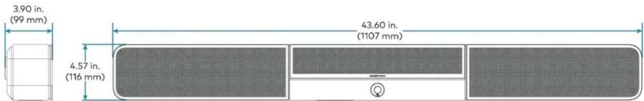
text_image
3.90 in. (99 mm) 4.57 in. (116 mm) 43.60 in. (1107 mm)Place on a Flat Surface
If the soundbar is to be placed on a flat surface, attach the included rubber feet to the bottom of the soundbar as shown.
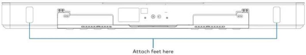
text_image
Attach feet hereMount on a Wall
The soundbar includes anchors that are suitable for mounting it on sheetrock walls up to 1/2 in. (13 mm thickness. Masonry and other materials may require additional installer-supplied mounting hardware.
NOTES:
- For optimal viewing results, the soundbar should be mounted in a location that places the camera approximately 12 in. (305 mm) above the plane of the room's conference table.
- When mounting on a wall beneath a display device, leave 3/4 in. (19 mm) (minimum) clearance above the top of the soundbar. Use the included template to allow for sufficient clearance between the soundbar and display device.
The following tools are required to mount the soundbar:
• Drywall saw (not included)
- Drill with 5/16 in. bit (not included)
A template is included to provide drill hole locations for the included mounting hardware.
- Attach the template to the desired mounting location with the template's center reference line at the center of the desired location.
NOTE: Use the center reference hole of the template as a guide to attach the template.
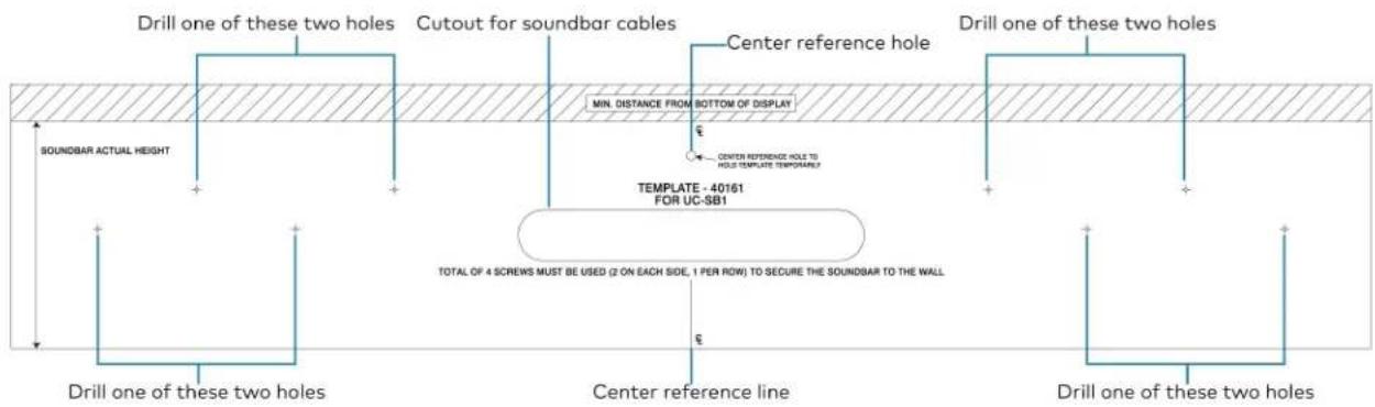
text_image
Drill one of these two holes Cutout for soundbar cables Center reference hole Drill one of these two holes SOUNDBAR ACTUAL HEIGHT MIN. DISTANCE FROM BOTTOM OF DISPLAY CENTER REFERENCE HOLE TO HOLD TEMPLATE TEMPORARY? TEMPLATE - 40161 FOR UC-SB1 TOTAL OF 4 SCREWS MUST BE USED (2 ON EACH SIDE, 1 PER ROW) TO SECURE THE SOUNDBAR TO THE WALL Center reference line Drill one of these two holes Drill one of these two holes- Drill two pilot holes on each side of the center reference line as shown in the previous diagram. Each side should have one pilot hole drilled in each row of the template.
- Use a drywall saw to make a cutout in the wall for the soundbar cables. The cutout in the center of the template provides adequate access for all of the required cabling.
-
Install the four included anchors and screws into the drilled pilot holes.
-
Place the soundbar face down, and pivot the wall bracket away from the soundbar.

text_image
Wall bracket Soundbar- Place the wall bracket over the screws, and hand tighten the screws until the wall bracket is secured to the wall.
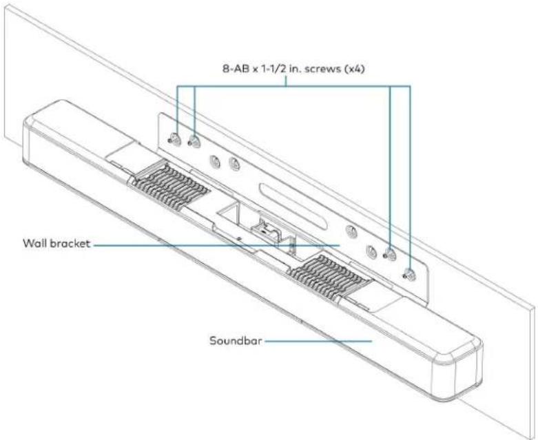
text_image
8-AB x 1-1/2 in. screws (x4) Wall bracket Soundbar- Route the cables through the cable cutout.
NOTE: The included power pack's cord is typically routed from the wall opening, through the cable cutout, to the soundbar.
Connect
Make the necessary connections as called out in the following diagram. Connect power last. Once all connections are made, pivot the soundbar up to the wall bracket until the soundbar locks into place.
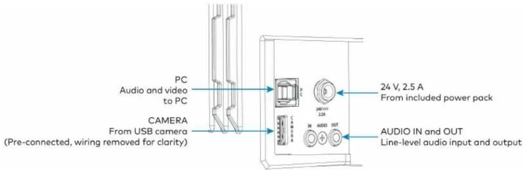
text_image
PC Audio and video to PC CAMERA From USB camera (Pre-connected, wiring removed for clarity) 24 V, 2.5 A From included power pack CAMERA IN AUDIO OUT AUDIO IN and OUT Line-level audio input and output- PC: Connect the included USB cable to the PC port and to a USB port on the computer. For optimal results, use a USB 3.0 connection.
• CAMERA: The integrated camera is already connected from the factory.
• 24 V, 2.5 A: Connect the power pack to the 24 V, 2.5 A power input and to an AC power outl
- AUDIO IN and AUDIO OUT: The soundbar provides unbalanced, stereo, analog input and output jacks (3.5 mm TRS mini-phone). The AUDIO IN port accommodates an optional line-level audio source which feeds to the internal amplifier and speakers without a volume control or other signal processing. The AUDIO OUT port provides a line-level signal for an optional assistive listening system and carries the same audio signal as the soundbar speakers.
Operation
Status
The front panel status bar illuminates to provide operational information.
- A green status bar indicates the volume level. Raising the volume increases the status bar's illumination. Lowering the volume decreases the status bar's illumination. When the volume = "O", the status bar is unlit.

natural_image
Pure diagram of a room layout with no text, numbers, or symbols- Muting the microphone and speaker turns the two outer segments of the status bar red.

natural_image
Pure diagram of a room layout with no text, numbers, or symbols- Muting the microphone turns the center of the status bar red.

natural_image
Top-down view of a modern office building (no signage)System Control
The soundbar can be used in a BYOD scenario where the soundbar is connected to an end-user's PC over USB. The soundbar will pass both camera and bidirectional (mic and speaker) audio across a single USB connection.
UC-SB-P50 and UC-SB-P50-INDIA
The Crestron UC-SB-P50 and UC-SB-P50-INDIA Jabra® PanaCast® 50 intelligent videobars for
Crestron Flex systems combines microphones, speakers, and cameras in one front-of-room device. High-quality speakers and microphones deliver exceptional full-duplex performance. Three built-in conferencing cameras capture the room in panoramic 4K resolution with a seamless 180° horizontal field of view. The Jabra PanaCast 50 is optimized for all leading UC platforms, including both Microsoft Teams Rooms and Zoom Rooms software.
For more information on the Jabra PanaCast 50 video bar for Crestron Flex systems, refer to Jabra PanaCast 50.

natural_image
Black cylindrical object with textured surface and a small black knob inserted at the end (no visible text or symbols)Installing UC-SB-P50 and UC-SB-P50-INDIA
Mount the Jabra PanaCast 50 intelligent video bar for Crestron Flex Systems according to its included documentation.
Crestron Flex Care (extended support)
This section provides the following information:
- UC-FLEXCARE
- UC-FLEXCARE-C
• UC-FLEXCARE-PSERIES
• UC-FLEXCARE-TA
UC-FLEXCARE
Crestron Flex Care UC-FLEXCARE Premium Crestron Flex Support for M, MM, B, or R-Series Systems is a subscription support plan available for purchase for terms of one year or longer in connection with the purchase of eligible Crestron Flex conference systems. ^12 The term of coverage under an active Crestron Flex Care subscription plan may be extended for a total period of coverage of up to five (5) years from the purchase of the covered Crestron Flex conference system, by purchasing additional subscription terms prior to the expiration of an active Crestron Flex Care subscription plan.
UC-B30-T (for reference purpose only)

natural_image
Modern black electronic device with a flat-screen screen displaying a colorful interface, alongside a black rectangular device (no visible text or symbols)Key Features
• 24/7 live remote support with a dedicated Crestron Flex team
• Rapid advance replacement
- Extends Crestron's standard limited warranty coverage period from three (3) years to a period of up to five (5) years, for all Crestron-branded hardware included in the covered Crestron Flex conference system, when continuous Crestron Flex Care coverage is maintained from initial purchase through the extended warranty period
- On site support discount
Crestron Flex Care subscriptions provide the benefits described below for the covered Crestron Flex conference system:
24/7 Live Support with Optional Cloud Connection
Crestron Flex Care guarantees 24/7, year round live remote support with a dedicated Crestron Flex support team.
Extended Hardware Warranty
The purchase of Crestron Flex Care extends Crestron's standard limited warranty coverage period from three (3) years to a period of up to five (5) years, for all Crestron-branded hardware included in the covered Crestron Flex conference system, when continuous Crestron Flex Care coverage is maintained from initial purchase through the extended warranty period.
Rapid Advance Replacement
If a replacement device is needed during the warranty period, Crestron will issue an advance replacement unit before the defective unit is sent back to ensure minimal downtime.
Discounted On-site Support
If on site support is needed, Crestron Flex Care subscribers are offered a discounted, all inclusive daily rate without any hidden fees or added costs for travel and expenses.
Specifications
Crestron Flex Care Services
| Support Hours | Live 24/7, year round remote technical support with a dedicated Crestron Flex support team |
| Advance Replacement | Replacement parts ship prior to the defective unit being shipped to Crestron during the warranty period ^14 |
| Extended Warranty | When Plan coverage is continuously maintained from initial purchase through the extended warranty period, the Crestron Standard Limited Warranty coverage period will be extended from three (3) years to a period of up to five (5) years from the purchase of the Eligible Product, for all Crestron-branded components of the Eligible Products. ^1,4 |
On-site Support Discounted, all-inclusive daily rate without any hidden fees 5
Notes:
- Detailed terms and conditions for Crestron Flex Care are posted at www.crestron.com/flexcareterms.
- Crestron Flex Care subscription support plans must be purchased within 90 days of Crestron's shipment of the covered Crestron Flex conference system.
- The period of Crestron Flex Care plan coverage may be extended by purchasing additional subscription terms prior to the expiration of an active Crestron Flex Care subscription plan, for a maximum period of coverage of up to five (5) years from Crestron's shipment of the covered Crestron Flex conference system. Crestron Flex Care plans and benefits will expire if continuous coverage is not maintained.
- The extended warranty applies only to Crestron branded components of the covered Crestron Flex conference system product. Crestron's Standard Limited Warranty applies to all third-party branded components, including the UC Engine and standalone cameras. Warranties and Advance Replacements are subject to the terms of Crestron Standard Limited Warranty and Terms and Conditions of Sale, posted at www.crestron.com/warranty.
- Subject to the terms of Crestron's On-Site Support program, where available. On-Site Support requires the engagement of an independent Crestron authorized Dealer. To locate a Dealer click the "How to Buy" tab at www.crestron.com.
This product may be purchased from select authorized resellers in the United States, Canada, Australia, New Zealand, and select regions in Europe.
UC-FLEXCARE-C
Crestron Flex Care UC-FLEXCARE-C Premium Crestron Flex Support for New C-Series Systems is a subscription support plan available for purchase for terms of one year or longer in connection with the purchase of eligible Crestron Flex conference systems. ^1,2 The term of coverage under an active Crestron Flex Care subscription plan may be extended for a total period of coverage of up to five (5) years from the purchase of the covered Crestron Flex conference system, by purchasing additional subscription terms prior to the expiration of an active Crestron Flex Care subscription ^3,4 plan.
UC-C100-T (for reference purpose only)
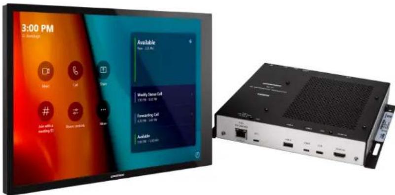
text_image
3:00 PM 3x 12 pages Next Take Stop # Job with a emailing ID Store click Available New: 12.5 MHz Weekly Status Call 136 MHz - 428 MHz Forecasting Call 4.25 MHz - 549 MHz Available 100 MHz - 1200 MHzKey Features
• 24/7 live remote support with a dedicated Crestron Flex team
• Rapid advance replacement
- Extends Crestron's standard limited warranty coverage period from three (3) years to a period of up to five (5) years, for all Crestron-branded hardware included in the covered Crestron Flex conference system, when continuous Crestron Flex Care coverage is maintained from initial purchase through the extended warranty period.
- On site support discount
Crestron Flex Care subscriptions provide the benefits described below for the covered Crestron Flex conference system:
24/7 Live Support with Optional Cloud Connection
Crestron Flex Care guarantees 24/7, year round live remote support with a dedicated Crestron Flex support team.
Extended Hardware Warranty
The purchase of Crestron Flex Care extends Crestron's standard limited warranty coverage period from three (3) years to a period of up to five (5) years, for all Crestron-branded hardware included in the covered Crestron Flex conference system, when continuous Crestron Flex Care coverage is maintained from initial purchase through the extended warranty period.
Rapid Advance Replacement
If a replacement device is needed during the warranty period, Crestron will issue an advance replacement unit before the defective unit is sent back to ensure minimal downtime.
Discounted On-site Support
If on site support is needed, Crestron Flex Care subscribers are offered a discounted, all inclusive daily rate without any hidden fees or added costs for travel and expenses.
Specifications
Crestron Flex Care Services
| Support Hours | Live 24/7, year round remote technical support with a dedicated Crestron Flex support team |
| Advance Replacement | Replacement parts ship prior to the defective unit being shipped to Crestron during the warranty period ^3 ^4 |
| Extended Warranty | When Plan coverage is continuously maintained from initial purchase through the extended warranty period, the Crestron Standard Limited Warranty coverage period will be extended from three (3) years to a period of up to five (5) years from the purchase of the Eligible Product, for all Crestron-branded components of the Eligible Products.1,4 |
On-site Support Discounted, all-inclusive daily rate without any hidden fees
Notes:
- Detailed terms and conditions for Crestron Flex Care are posted at www.crestron.com/flexcareterms.
- Crestron Flex Care subscription support plans must be purchased within 90 days of Crestron's shipment of the covered Crestron Flex conference system.
- The period of Crestron Flex Care plan coverage may be extended by purchasing additional subscription terms prior to the expiration of an active Crestron Flex Care subscription plan, for a maximum period of coverage of up to five (5) years from Crestron's shipment of the covered Crestron Flex conference system. Crestron Flex Care plans and benefits will expire if continuous coverage is not maintained.
- The extended warranty applies only to Crestron branded components of the covered Crestron Flex conference system product. Crestron's Standard Limited Warranty applies to all third-party branded components, including the UC Engine and standalone cameras. Warranties and Advance Replacements are subject to the terms of Crestron Standard Limited Warranty and Terms and Conditions of Sale, posted at www.crestron.com/warranty.
- Subject to the terms of Crestron's On-Site Support program, where available. On-Site Support requires the engagement of an independent Crestron authorized Dealer. To locate a Dealer click the "How to Buy" tab at www.crestron.com.
This product may be purchased from select authorized resellers in the United States, Canada, Australia, New Zealand, and select regions in Europe.
UC-FLEXCARE-PSERIES
Crestron Flex Care UC-FLEXCARE-PSERIES Premium Crestron Flex Support for New P-Series Phones is a subscription support plan available for purchase for terms of one year or longer in connection with the purchase of eligible Crestron Flex conference systems. The term of coverage under an active Crestron Flex Care subscription plan may be extended for a total period of coverage of up to five (5) years from the purchase of the covered Crestron Flex conference system, by purchasing additional subscription terms prior to the expiration of an active Crestron Flex Care subscription plan.
UC-P8-T (for reference purpose only)
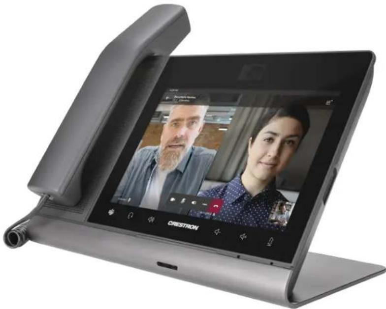
natural_image
Exterior view of a modern office desk with a large screen displaying two people, one open and one closed, labeled 'CRESTRON' (no readable text on screen or surroundings)Key Features
• 24/7 live remote support with a dedicated Crestron Flex team
• Rapid advance replacement
- Extends Crestron's standard limited warranty coverage period from three (3) years to a period of up to five (5) years, for all Crestron-branded hardware included in the covered Crestron Flex conference system, when continuous Crestron Flex Care coverage is maintained from initial purchase through the extended warranty period
- On site support discount
Crestron Flex Care subscriptions provide the benefits described below for the covered Crestron Flex conference system:
24/7 Live Support with Optional Cloud Connection
Crestron Flex Care guarantees 24/7, year round live remote support with a dedicated Crestron Flex support team.
Extended Hardware Warranty
The purchase of Crestron Flex Care extends Crestron's standard limited warranty coverage period from three (3) years to a period of up to five (5) years, for all Crestron-branded hardware included in the covered Crestron Flex conference system, when continuous Crestron Flex Care coverage is maintained from initial purchase through the extended warranty period.
Rapid Advance Replacement
If a replacement device is needed during the warranty period, Crestron will issue an advance replacement unit before the defective unit is sent back to ensure minimal downtime.
Discounted On-site Support
If on site support is needed, Crestron Flex Care subscribers are offered a discounted, all inclusive daily rate without any hidden fees or added costs for travel and expenses.
Specifications
Crestron Flex Care Services
| Support Hours | Live 24/7, year round remote technical support with a dedicated Crestron Flex support team |
| Advance Replacement | Replacement parts ship prior to the defective unit being shipped to Crestron during the warranty period ^3 ^4 |
| Extended Warranty | When Plan coverage is continuously maintained from initial purchase through the extended warranty period, the Crestron Standard Limited Warranty coverage period will be extended from three (3) years to a period of up to five (5) years from the purchase of the Eligible Product, for all Crestron-branded components of the Eligible Products.1,4 |
On-site Support Discounted, all-inclusive daily rate without any hidden fees
Notes:
- Detailed terms and conditions for Crestron Flex Care are posted at www.crestron.com/flexcareterms.
- Crestron Flex Care subscription support plans must be purchased within 90 days of Crestron's shipment of the covered Crestron Flex conference system.
- The period of Crestron Flex Care plan coverage may be extended by purchasing additional subscription terms prior to the expiration of an active Crestron Flex Care subscription plan, for a maximum period of coverage of up to five (5) years from Crestron's shipment of the covered Crestron Flex conference system. Crestron Flex Care plans and benefits will expire if continuous coverage is not maintained.
- The extended warranty applies only to Crestron branded components of the covered Crestron Flex conference system product. Crestron's Standard Limited Warranty applies to all third-party branded components, including the UC Engine and standalone cameras. Warranties and Advance Replacements are subject to the terms of Crestron Standard Limited Warranty and Terms and Conditions of Sale, posted at www.crestron.com/warranty.
- Subject to the terms of Crestron's On-Site Support program, where available. On-Site Support requires the engagement of an independent Crestron authorized Dealer. To locate a Dealer click the "How to Buy" tab at www.crestron.com.
This product may be purchased from select authorized resellers in the United States, Canada, Australia, New Zealand, and select regions in Europe.
UC-FLEXCARE-TA
Crestron Flex Care UC-FLEXCARE-TA Premium Crestron Flex Support for New UC-MM30-TA(-I) Systems is a subscription support plan available for purchase for terms of one year or longer in connection with the purchase of eligible Crestron Flex conference system. ^1,2 The term of coverage under an active Crestron Flex Care subscription plan may be extended for a total period of coverage of up to five (5) years from the purchase of the covered Crestron Flex conference system, by purchasing additional subscription terms prior to the expiration of an active Crestron Flex Care subscription plan. ^3
UC-MM30-TA (for reference purpose only)

natural_image
Exterior view of a modern office building (no signage)Key Features
• 24/7 live remote support with a dedicated Crestron Flex team
• Rapid advance replacement
- Extends Crestron's standard limited warranty coverage period from three (3) years to a period of up to five (5) years, for all Crestron-branded hardware included in the covered Crestron Flex conference system, when continuous Crestron Flex Care coverage is maintained from initial purchase through the extended warranty period
- On site support discount
Crestron Flex Care subscriptions provide the benefits described below for the covered Crestron Flex conference system:
24/7 Live Support with Optional Cloud Connection
Crestron Flex Care guarantees 24/7, year round live remote support with a dedicated Crestron Flex support team.
Extended Hardware Warranty
The purchase of Crestron Flex Care extends Crestron's standard limited warranty coverage period from three (3) years to a period of up to five (5) years, for all Crestron-branded hardware included in the covered Crestron Flex conference system, when continuous Crestron Flex Care coverage is maintained from initial purchase through the extended warranty period.
Rapid Advance Replacement
If a replacement device is needed during the warranty period, Crestron will issue an advance replacement unit before the defective unit is sent back to ensure minimal downtime.
Discounted On-site Support
If on site support is needed, Crestron Flex Care subscribers are offered a discounted, all inclusive daily rate without any hidden fees or added costs for travel and expenses.
Specifications
Crestron Flex Care Services
| Support Hours | Live 24/7, year round remote technical support with a dedicated Crestron Flex support team |
| Advance Replacement | Replacement parts ship prior to the defective unit being shipped to Crestron during the warranty period ^3 ^4 |
| Extended Warranty | When Plan coverage is continuously maintained from initial purchase through the extended warranty period, the Crestron Standard Limited Warranty coverage period will be extended from three (3) years to a period of up to five (5) years from the purchase of the Eligible Product, for all Crestron-branded components of the Eligible Products.1,4 |
On-site Support Discounted, all-inclusive daily rate without any hidden fees
Notes:
- Detailed terms and conditions for Crestron Flex Care are posted at www.crestron.com/flexcareterms.
- Crestron Flex Care subscription support plans must be purchased within 90 days of Crestron's shipment of the covered Crestron Flex conference system.
- The period of Crestron Flex Care plan coverage may be extended by purchasing additional subscription terms prior to the expiration of an active Crestron Flex Care subscription plan, for a maximum period of coverage of up to five (5) years from Crestron's shipment of the covered Crestron Flex conference system. Crestron Flex Care plans and benefits will expire if continuous coverage is not maintained.
- The extended warranty applies only to Crestron branded components of the covered Crestron Flex conference system product. Crestron's Standard Limited Warranty applies to all third-party branded components, including the UC Engine and standalone cameras. Warranties and Advance Replacements are subject to the terms of Crestron Standard Limited Warranty and Terms and Conditions of Sale, posted at www.crestron.com/warranty.
- Subject to the terms of Crestron's On-Site Support program, where available. On-Site Support requires the engagement of an independent Crestron authorized Dealer. To locate a Dealer click the "How to Buy" tab at www.crestron.com.
This product may be purchased from select authorized resellers in the United States, Canada, Australia, New Zealand, and select regions in Europe.
Crestron Flex Supported Products
Discontinued Solutions
To install the discontinued Crestron Flex solutions listed below, follow the respective link to the Quick Start guide for instructions.
| Crestron Flex Solutions Quick Start Guide | |
| UC-MM30-T-LUC-MM30-T-L-I | Quick Start: UC-MM30-T-L(-I) |
| UC-MM30-Z-LUC-MM30-Z-L-I | Quick Start: UC-MM30-Z-L(-I) |
| UC-MMX30-T-LUC-MMX30-T-L-I | Quick Start: UC-MMX30-T-L(-I) |
| UC-MMX30-Z-LUC-MMX30-Z-L-I | Quick Start: UC-MMX30-Z-L(-I) |
| UC-B30-T-L Quick Start: UC-B30-T-L | ____ |
| UC-B30-Z-L Quick Start: UC-B30-Z-L | ____ |
| UC-BX30-T-L Quick Start: UC-BX30-T-L | ____ |
| UC-BX30-Z-L Quick Start: UC-BX30-Z-L | ____ |
| UC-B30-T-L-WM Quick Start: UC-B30-T-L-WM | ____ |
| UC-B30-Z-L-WM Quick Start: UC-B30-Z-L-WM | ____ |
| UC-BX30-T-L-WM Quick Start: UC-BX30-T-L-WM | ____ |
| UC-BX30-Z-L-WM Quick Start: UC-BX30-Z-L-WM | ____ |
| UC-B160-T Quick Start: UC-B160-T | ____ |
| UC-B160-Z Quick Start: UC-B160-Z | ____ |
| UC-M50-T-L Quick Start: UC-M50-T-L | ____ |
| UC-M50-Z-L | Quick Start: UC-M50-Z-L |
| UC-MX50-T-L | Quick Start: UC-MX50-T-L |
| UC-MX50-Z-L | Quick Start: UC-MX50-Z-L |
| UC-C160-T Quick Start: UC-C160-T | ____ |
| UC-C160-Z | Quick Start: UC-C160-Z |
| UC-C100-T-L | Quick Start: UC-C100-T-L |
| UC-C100-Z-L Quick Start: UC-C100-Z-L | ____ |
| UC-C100-T-L-WM | Quick Start: UC-C100-T-L-WM |
| UC-C100-Z-L-WM Quick Start: UC-C100-Z-L-WM | |
| UC-CX100-T-L Quick Start: UC-CX100-T-L | |
| UC-CX100-Z-L Quick Start: UC-CX100-Z-L | |
| UC-CX100-T-L-WM Quick Start: UC-CX100-T-L-WM | |
| UC-CX100-Z-L-WM Quick Start: UC-CX100-Z-L-WM | |
| UC-FCM-TUC-FCM-ZUC-FCM-U | Quick Start: UC-FCM Series |
| UC-FCB-TUC-FCB-Z | Quick Start: UC-FCB Series |
| UC-FCMX-TUC-FCMX-Z | Quick Start: UC-FCMX Series |
Resources
The following resources are provided for the Crestron Flex conferencing solutions.
NOTE: You may need to provide your Crestron.com web account credentials when prompted to access some of the following resources.
Crestron Support
- Crestron True Blue Support
- Crestron Resource Library
• Crestron Online Help (OLH)
Crestron Training Institute (CTI) Portal
The series of courses that offer successful deployment of Crestron Flex solutions. For details, refer to Crestron Flex training courses.
Security Reference Guides
- Crestron Flex UC-ENGINE
- Crestron Flex Phones
• Crestron Flex Care Cloud Connect Service - XiO Cloud® Provisioning and Management Service
• TS-70 and TSW-70 Series Touch Screens
Configuration Guides for Crestron Mercur and Mercury X
- Secure SIP Endpoint with Cisco® Unified Communications Manager 11.0 for CCS-UC-1
- Secure SIP Endpoint with Avaya Aura® 7.0 System for CCS-UC-1
- Crestron Mercury Tabletop Conference System (CCS-UC-1 & CCS-UC-1-X) TLS Secure SIP Endpoint with Avaya Aura® 8.0 Communication Manager
- Crestron Mercury® Tabletop Conference System (CCS-UC-1 & CCS-UC-1-X) Non Secure SIP Endpoint with Cisco® 12.5 Unified Communication Manager (CUCM)
- Crestron Mercury Tabletop Conference System with Microsoft® Skype® for Business for CCS-UC-1
- SIP Endpoint with Cisco® Unified Communications Manager 10.5 for CCS-UC-1
- Secure SIP Endpoint with Cisco® Unified Communications Manager 10.5 for CCS-UC-1
- SIP Endpoint with Mitel® MiVoice Business System 8.0PR3 for CCS-UC-1
- SIP Endpoint with ShoreTel® Connect System 21.80.7840.0 for CCS-UC-1
- SIP Endpoint with Avaya Aura® 6.3 System for CCS-UC-1
- SIP Endpoint with Avaya Aura® 7.0 System for CCS-UC-1
Product Information (Compliance) Sheet
• Product Information: UC M, MM, B, C, and R Series KIT
• Product Information: UC-2-T-V and UC-2-T-V-I
• Product Information: UC-2-Z and UC-2-Z-I
• Product Information: CCS-UC-1-X
• Product Information: UC-PR
• Product Information: UC-BRKT-250-P-T-ASSY
• Product Information: UC-BRKT-200-S-T-ASSY
• Product Information: UC-BRKT-260-P-T-ASSY
• Product Information: UC-BRKT-260-P-Z-ASSY
• Product Information: UC-BRKT-250-P-Z-ASSY
• Product Information: UC-BRKT-200-S-Z-ASSY
• Product Information: UC-SB1-CAM-FLEX
• Product Information: ADPT-USB3.0-GBENET
• Product Information: CCS-UCA-MIC
• Product Information: UCA-PWE-UC-2/UC-P8/P10
• Product Information: UCA-RMK-1U
• Product Information: UC-SB1
• Product Information: UC-SB1-CAM
• Product Information: UCA-SMK-UC2 and UCA-SMKR-UC2-3
Product Certificates
To search for product certificates, refer to support.crestron.com/app/certificates.
Programmer and Developer Resources
- help.crestron.com: Provides help files for Crestron programming tools such as SIMPL, SIMPL#, and Crestron Toolbox™ software
- developer.crestron.com: Provides developer documentation for Crestron APIs, SDKs, and other development tools