
U1000 - Exercise bike BodyCraft - Free user manual and instructions
Find the device manual for free U1000 BodyCraft in PDF.

| Product Type | Upright Exercise Bike |
| Model | U1000 (U1K1-V2) |
| Brand | BodyCraft |
| Maximum User Weight | 400 lbs (181 kg) |
| Dimensions (Approx.) | 52" L x 13" W x 31" H (shipping box for main frame) |
| Weight (Approx.) | 170 lbs (main frame shipping weight) |
| Power Requirements | 120VAC / 15A dedicated outlet for touch screen consoles (10" and 16"); 9" LCD is self-powered (battery) or optional adaptor 12VDC/3A |
| Console Options | 9" LCD (self-powered), 10" Touch Screen, 16" Touch Screen |
| Heart Rate Monitoring | Stainless steel pulse hand grips; built-in wireless receiver (5 KHz / Bluetooth) for chest strap (not included) |
| Energy Saving | Automatic power off after 10 minutes of inactivity |
| Pedal Type | Left and right pedals with markings (L/R), threaded, requires 15mm wrench, torque 25-30 ft-lbs |
| Seat Adjustment | Adjustable seat height via pull bar while seated |
| Transport | Transport wheels; lift rear stabilizer to roll |
| Leveling | Four adjustable levelers on front and rear stabilizers |
| Warranty (Residential) | Frame: Lifetime, Parts: 10 years, Console: 3 years, Labor: 2 years |
| Warranty (Commercial) | Frame: 10 years, Parts: 5 years, Console: 3 years, Labor: 2 years |
| Cleaning | Mild soap and water; avoid acidic or abrasive cleaners; use microfiber cloth for console |
| Maintenance | Annually retorque external bolts; keep area clean; check for loose/worn parts before use |
| Assembly Tools Required | Phillips screwdrivers, Allen wrenches (4-10mm), socket set 3/8" drive, pedal wrench 15mm, torque wrench |
| Certification | FCC Part 15 Class B |
| Registration | Required within 30 days for warranty at www.bodycraft.com/product-registration |
Frequently Asked Questions - U1000 BodyCraft
User questions about U1000 BodyCraft
0 question about this device. Answer the ones you know or ask your own.
Ask a new question about this device
Download the instructions for your Exercise bike in PDF format for free! Find your manual U1000 - BodyCraft and take your electronic device back in hand. On this page are published all the documents necessary for the use of your device. U1000 by BodyCraft.
USER MANUAL U1000 BodyCraft
natural_image
Black BodyCraft 2.0 exercise bike with digital display and control panel (no visible text or symbols on the bike itself)U1000-V2 Upright Bike
To see in FULL COLOR & additional information, scan this QR code.

Base Serial Number: U
Console Serial Number: ____
Purchased Date: ____ / ____ / ____
Dealer's Name:
Please register your products at:
https://www.bodycraft.com/product-registration/

Base Serial Number
Owner's Manual
(U1K1-V2)_OM_v 1.5

WWW.BODYCRAFT.COM

800-990-5556

SERVICE@BODYCRAFT.COM
Congratulations and Welcome to the BODYCRAFT Family
Thank you for selecting BODYCRAFT. Your choice reflects a wise investment in you and your facility. We hope you use it for many healthy years!
BODYCRAFT offers a complete array of high-quality fitness equipment. Please refer to our website at www.bodycraft.com to view more ways to enhance your lifestyle.
Your BODYCRAFT machine has all the quality and design elements to make your workout extremely efficient and comfortable. Your new unit is a serious cardio machine that will keep you motivated, challenged and within reach of your fitness goals. Strength & cardiovascular training is vital for all ages which will provide an effective workout, producing results that will encourage you to reach your fitness goals and maintain the body you have always wanted.
Spending 15 to 30 minutes a day, three times a week, is all you need to start seeing the benefits of a regular exercise program.
As a premium exercise equipment manufacturer, we are committed to your complete satisfaction. If you have questions, suggestions or find missing or damaged parts, we guarantee your complete satisfaction through our authorized dealer network or by contacting us directly. Please call your local dealer or BODYCRAFT.
BODYCRAFT (a division of Recreation Supply, Inc.)
7699 Green Meadows Dr.
Lewis Center, OH 43035
Phone: 800-990-5556 9 am - 5 pm EST Email: service@bodycraft.com
Proof of purchase must be supplied to validate warranty and the product must have been
registered with BODYCRAFT via online at www.bodycraft.com or by calling 800-990-5556
or 740-965-2442 M-F 9 a.m. - 5 p.m. EST.
For parts orders, owner's manuals, software update files, exercise guides and contact information scan this QR code.
Or go to:
https://www.bodycraft.com/customer-support


Table of Contents

NOTE: When you have downloaded the Assembly Manual into a PDF reader, go directly to the desired page by touching any BLUE line in this Table of Contents.
Page
Product Safety Information
FCC Information 4
Product Safety 5 - 6
Product Overview
Product Overview Components & Tools for Assembly 7
Hardware Identification Chart 8
Assembly Parts 9
Shipping Boxes and What's Inside Each One ....10
How Assemble the Upright Bike
Product Assembly Instructions 11 - 23
Operation Instructions
Operating Instruction 25 - 26
Cleaning your Bike 27
Heart Rate Monitoring Grips & Wireless Receiver ....28
Erratic Heart Rate Readings & Exercise Tips 29
Installation Checklist 30

Energy saving
Energy Saving function: These consoles are equipped with power saving function. This means after 10 minutes of inactivity it will automatically power off. Press any key on the console for X-9LCD or touch the screen for X-10TS/X-16TS to wake up the console from power save mode.
Table of Contents

NOTE: When you have downloaded the Assembly Manual into a PDF reader, go directly to the desired page by touching any BLUE line in this Table of Contents.
Page
Maintenance & Repairs
Information Needed Prior to Contacting Customer Support .... 31
Circuit Diagram 32
Detailed Parts Lists 33 - 34
Detailed Parts Exploded View 35
Warranty
Product Warranty ....36
Product Warranty Registration 37
Contact Us Information ....38
FCC Information
Caution: Please note that changes or modifications not expressly approved by the party responsible for compliance could void the user's authority to operate the equipment.
This device complies with Part 15 of the FCC Rules. Operation is subject to the following two conditions: (1) This device may not cause harmful interference, and (2) this device must accept any interference received, including interference that may cause undesired operation.
NOTE: This equipment has been tested and found to comply with the limits for a Class B digital device, pursuant to Part 15 of the FCC Rules. These limits are designed to provide reasonable protection against harmful interference in a residential installation. This equipment generates, uses and can radiate radio frequency energy and, if not installed and used in accordance with the instructions, may cause harmful interference to radio communications. However, there is no guarantee that interference will not occur in a particular installation. If this equipment does cause harmful interference to radio or television reception, which can be determined by turning the equipment off and on, the user is encouraged to try to correct the interference by one or more of the following measures:
Reorient or relocate the receiving antenna.
Increase the separation between the equipment and receiver.
Connect the equipment into an outlet on a circuit different from that to which the receiver is connected.
Consult the dealer or an experienced radio/TV technician for help.
FCC CAUTION: Changes or modifications not expressly approved by the party responsible for compliance could void the user's authority to operate this equipment.

There is a risk assumed by individuals who use this type of equipment. A moment's lack of attention can result in an accident, as can failure to observe certain simple safety precautions.
Read, study and understand the Assembly Instructions and all the warning labels on this product. Furthermore, it is recommended to familiarize yourself and others with the proper operation and workout recommendations for this BODYCRAFT product prior to use.
- We recommend that two people be available for moving and assembly of this product.
- Keep children away from the Bike. Do not allow children to use or play on the Bike.
- Keep children and pets away from the Bike when it is in use.
- It is recommended that you place this exercise equipment on an equipment mat.
- Set up and operate the Bike on a solid level surface. Do not position the Bike on loose rugs or uneven surfaces.
- Inspect the Bike for worn or loose components prior to use.
- Tighten/replace any loose or worn components prior to using the Bike.
- Always choose the workout which best fits your physical strength and flexibility level. Know your limits and train within them.
- Always use common sense when exercising.
- Keep hands, limbs, loose clothing and long hair well out of the way of moving parts.
- Do not wear loose or dangling clothing while using the Bike.
- Never exercise in bare feet or socks; always wear correct footwear, such as running, walking, or cross-training shoes.
- Be careful to maintain your balance while using, mounting, dismounting, or assembling the Bike. Loss of balance may result in a fall and serious bodily injury.
Safety and Warnings - Bike
- Keep both feet firmly and securely on the Foot Pedals while exercising.
- This Bike should not be used by persons weighing over 400 pounds /181 kgs.
- The Bike should be used by only one person at a time.
- Make sure that adequate space is available for access to and passage around the Bike; keep at least a distance of 3 feet from any object while using the machine.
- This Bike is designed for commercial and home usage.
- Maintenance:
- Replace any defective components immediately and/or keep the equipment out of use until the equipment is completely repaired.
- Clean seat, plastic and frame on a regular basis. We recommend warm, soapy water. Do not use harsh or abrasive chemicals.
WARNING: Before using this product or any exercise or conditioning program, you should consult with your personal physician to see if you require a complete physical exam. This is especially important if you have never exercised before, are pregnant, or suffer from any illness. Follow your physician's recommendations in developing your own personal fitness program.
READ AND FOLLOW THE SAFETY PRECAUTIONS. FAILURE TO FOLLOW THESE INSTRUCTIONS CAN RESULT IN SERIOUS BODILY INJURY.

Product Overview Components and Tools for Assembly

THE FOLLOWING TOOLS ARE INCLUDED FOR ASSEMBLY:

THE FOLLOWING TOOLS ARE RECOMMENDED FOR EASIER ASSEMBLY:

SOCKET SET 38 drive w/ 3" & 6"
EXTENSION for 13mm & 17mm

OPEN & CLOSED WRENCHES
for 13mm & 17mm

ALLEN WRENCHES SET
4mm to 10mm

natural_image
Two screwdrivers with different sizes and colors (black, red, yellow) on a white background, no text or symbols visible.PHILLIPS SCREWDRIVERS
2 w/ Magnetic TIP

EXTRA LONG PEDAL
WRENCHES 15mm (min 8" long)

TORQUE WRENCH 38 DRIVE w/ 5mm & 6mm Allen Sockets
Hardware Identification Chart
Unpack the box in a clear area. Use the List of Hardware below to check the contents of the hardware kit. This chart is provided to help identify the hardware used in the assembly process. Place the washers, the end of bolts, or screws on the circles to check for the correct diameter. Use the ruler to check the length of the bolts and screws.

bubble
| Measurement | Diameter (inches) | |-------------|------------------| | 3/16" | 3/16" | | 1/4" | 1/4" | | 5/16" | 5/16" | | 3/8" | 3/8" | | 1/2" | 1/2" | | 0 | 0 | | 1/2 | 1/2 | | 1 | 1 | | 1/2 | 1/2 | | 2 | 2 | | 1/2 | 1/2 | | 3 | 3 | | 1/2 | 1/2 | | 4 | 4 | | 1/2 | 1/2 | | 5 | 1/2 | | 1/2 | 1/2 | | 6 | 6 | | 8 | 8 | | 10 | 10 | | 12 | 12 |NOTICE: The length of all bolts and screws except those with flat heads is measured from below the head to the end of the bolt or screw. Flat head bolts and screws are measured from the top of the head to the end of the bolt or screw.


Please review below to know the content of the hardware kit. If a part is not in the hardware bag, check to see if it has been preassembled.
| 99 Bolt, Hex Head (M8xp1.25x65mm) 4pcs[IMAGE]84 Self-Tapping Screw, Flat Head (M4x32mm)4pcs<????????B136 Bolt, Hex Head Flange (M8xp1.25x16mm)7pcs[IMAGE] |  | 76 Washer (8x38x2.0t) | 4pcs |
 | 74 Lock Washer (M8) | 4pcs | |
 | 115 Lock Washer (M6) | 6pcs | |
 | 116 Bolt, Socket Head (M6xp1.0x15mm) | 2 pcs | |
 | 81 Washer (6x13x1.0t) | 6 pcs | |
 | 132 Nut Cap (M8) | 1 pcs | |
 | 85 Self-Tapping Screw, Flat Head (M4×20mm) | 3 pcs | |
 | 87 Screw, Round Head (M5×p0.8×15mm) | 5 pcs | |
 | 101 Bolt, Hex Head (M10xp1.5x25mm) | 2 pcs | |
 | 135 Screw, Phillips Pan Head (M6xp1.0x×15mm) | 4 pcs |
Assembly Parts
Unpack the box in a clear area. Follow the List of Assembly Parts below to check and make sure all assembly parts are present and in good condition. Do not dispose of the packing material until the assembly process is completed. Assembly tools and hardware kit have included for you to use when assembling the product
| Back Console Case(34) | Screw Cap (35) x 4 Forearm Pads (28) x 2 | Adaptor (137) & Power Cord(139) | |
 |  | [Adaptor>12DC/3A] | |
| Accessory Tray (37) &Support Pad (36) | Front & Rear Tube Cover(123, 124) | Console Tube - Assembly(33-ASM) | Handlebar - Assembly (6-ASM) |
| Upright Post Sleeve(38, 39) | Upright Post - Assembly(5-ASM) | Console (31) | Front & Rear Stabilizer -Assemblies (2-ASM, 3-ASM) |
| Pedals (11, 12) Main | Frame - Assembly (1-ASM) Leveler (19) x 4 | Hardware Kit (HWK) | |
NOTE: 9" LCD Console will NOT REQUIRES the Power Adaptor (137) & Power Cord (139) for use. ONLY use for the 16" & 10" Touch Screen Consoles or charging the battery, if needed, for the 9" LCD console.
Shipping Boxes and What's Inside Each One
Large Box 1 of 2
1 each @ 170 lbs
52" x 13" x 31"

CAUTION

Two person lift required.

natural_image
Exterior view of a BodyCraft exercise bike with various components laid out on a cardboard box (no visible text or symbols)Small Box 2 of 2
1 each @ 9 lbs
(9LCD/10TS)
or
1 each @ 10 lbs (16TS)
19" × 6.25" × 5"
(Includes the console
model that was ordered)


Note: Shown above with the upgraded 16TS console
BODYCRAFT reserves the right to make improvements at any time which may affect color, parts, materials, size, weight, or any other aspect.
Product Assembly - STEP 1
TIP: Place all parts from the boxes in a cleared area and position them on the floor in front of you.
Remove all packing materials from your area and place them back into the box. Do not dispose of the packing materials until assembly is completed.
Read each step carefully before beginning.
STEP 1 – Install Levelers to Stabilizer Assemblies


natural_image
Close-up of a dark gray mechanical component with a black clip, possibly a tool or fixture (no visible text or symbols)| Part # Description Qty | |
| U1K1-002-ASM Front Stabilizer - Assembly 1 | |
| U1K1-003-ASM Rear Stabilizer - Assembly 1 | |
| U1K1-019 Leveler 4 |

natural_image
Black BodyCraft device with circular vent and white base on cardboard table (no visible text or symbols)TIP: In order to assemble the Stabilizer Assemblies smoothly, it is suggested to place one Styrofoam (or any stationary object) under the back side of the Main Frame - Assembly.
STEP 2a - Install the Front & Rear Stabilizer Assemblies

| Part # Description Qty | |
| U1K1-001-ASM Main Frame - Assembly 1 | |
| U1K1-002-ASM Front Stabilizer - Assembly 1 | |
| U1K1-003-ASM Rear Stabilizer - Assembly 1 | |
| U1K1-074 Lock Washer (M8) 4 | |
| U1K1-076 Washer (M8 × 38 × 2.0t) 4 | |
| U1K1-099 Bolt (M8 × p1.25 × 65mm) 4 |

STEP 2b "Torque Time" -
Tighten the Hex Bolts (#99) to the recommended 20 ft-lbs +/- 2 lbs.

natural_image
Exterior view of a black wheeled device with attached mechanical components on a beige surface (no visible text or symbols)
natural_image
Close-up of a black mechanical device with mounting brackets and a transparent visor, mounted on a yellow surface (no visible text or symbols)
STEP 3a - Install Upright Post Assembly
| Part # Description Qty | ||
| U1K1-001-ASM | Main Frame - Assembly 1 | |
| U1K1-005-ASM | Upright Post - Assembly 1 | |
| U1K1-101 Bolt (M10 × p1.5 × 25mm) 2 | ||
| U1K1-109 | Nylon Nut (M10 × p1.5)NOTE: PreAssembled on Main Frame 2 | |

CAUTION
Pinch Point
Keep hands clear of edges


natural_image
Close-up of a mechanical component with black and yellow surfaces, showing internal wiring and mounting holes (no text or symbols visible)STEP 4a - Connect Wire Cables from Main Frame to Upright Post
NOTE: Make sure all wire connectors fully click when connected to each other. Also be careful not to pinch the wires when assembling STEP 4.


STEP 4b – Install Upright Post Sleeves

| Part # | Description Qty | |
| U1K1-038 | Left Upright Post Sleeve 1 | |
| U1K1-039 | Right Upright Post Sleeve 1 | |
| U1K1-085 | Screw (M4 x 20mm)NOTE: Self-Tapping 1 | |
| U1K1-087 | Screw (M5 × p0.8 × 15mm) 4 |
STEP 5 - Install Handlebar Assembly & "Torque Time"


natural_image
Close-up of a mechanical device with plastic-wrapped items and wires, no visible text or symbolsTIP: Filling-the-Gap with the extra parts plastic bag, keeps potential bolts & tools from accidentally falling into frame.
| Part # Description Qty | ||
| U1K1-006-ASM | Handlebar - Assembly 1 | |
| U1K1-136 Bolt (M8 x p1.25 x 16mm) 4 | ||

natural_image
Hand holding a black mechanical device with plastic wrapped around it, against a yellow background (no visible text or symbols)TIP: Using an extra parts plastic bag will help keep the Front Tube Cover (123) from sliding off or in the way during assembly.
STEP 6 - Install Tube Cover

| Part # Description Qty | |
| U1K1-033-ASM Console Tube - Assembly 1 | |
| U1K1-123 Front Tube Cover 1 |
STEP 7a – Install Console Tube Assembly & Wires

STEP 7b - Console Tube Alignment & "Torque Time"

TIP: Console tube alignment is easily done with tape measure before torquing bolts down. This ensures the new large console is level. Scan the QR code below to see Video on YouTube.
https://youtu.be/7p
3x|YCW2O4


natural_image
Close-up of a metallic mechanical component with black brackets and bolts, no visible text or symbols
Please confirm all bolts/nuts are tightened at this time, then continue to next Step.

STEP 8 - Install Tube Covers

85 Self-Tapping Screw,
NOTE: Both top holes use the #85 Self-Tapping Screws.

87 Screw,
NOTE: Lower center hole use the #87 Rounded Head Screw, machine threaded at 5mm.
Recommended Tool:

PHILLIPS SCREWDRIVER #2
w/ Magnetic TIP
STEP 9 – Install Bolt, "Torque Time" & Nut Cap


| Part # | Description Qty | |
| U1K1-085 | Screw (M4 x 20mm)NOTE: Self-Tapping | 2 |
| U1K1-087 | Screw (M5 × p0.8 × 15mm) 1 | |
| U1K1-132 | Nut Cap (M8) 1 | |
| U1K1-136 | Bolt (M8 x p1.25 x 16mm) 1 |
STEP 10 - Install Console

Recommended Tool:

PHILLIPS SCREWDRIVER #2
w/ Magnetic TIP

| Part # Description Qty | |
| U1K1-031 Console 1 | |
| U1K1-081 Washer (M6 x 13 x 1.0t) 4 | |
| U1K1-115 Lock Washer (M6) 4 | |
| U1K1-135 Screw, Phillips Pan Head (M6 x p1.0 x 15mm) 4 |
STEP 11a – Connect Console Wiring
a. Connect the Console Connection Wire (#31a) to the First Connection Wire (#112).
b. Connect the Console Pulse Sensor Wire (#31b) to the First Pulse Sensor Wire (#118).
c. For LCD console, connect the Console Battery Wire (#31c) to the Battery Connection Wire #140) for self-powered function
NOTE: These wires (#31c) and (#140) are ONLY for the Self-Powered LCD Console.

Be Careful To Not Pinch Wires


STEP 11b - Install Console Cover

84 Self-Tapping Screw, Flat Head

| Part # Description Qty | |
| U1K1-031 Console 1 | |
| U1K1-034 Back Console Case 1 | |
| U1K1-035 Screw Cap 4 | |
| U1K1-084 Screw (M4 × 32mm) 4 |

Please confirm all screws are tightened at this time, then continue to next Step.
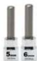
STEP 12 - Install Forearm Pads & "Torque Time"
TIP: Inside the handrails is the Heart Rate Cable. This gets in the way to assemble the Elbow Pads. Use a phillips screwdriver and push the wire to a side.

natural_image
Close-up of a black athletic bike handle with metal pins and circular holes (no text or symbols visible)
natural_image
Close-up of a black plastic curved component with a tool inserted, showing a hole and circular opening (no text or symbols visible)
| Part # Description Qty | ||
| U1K1-028 Hand Wrist Pad 2 | ||
| U1K1-081 Washer (M6 x 13 x 1.0t) 6 | ||
| U1K1-115 Lock Washer (M6) 6 | ||
| U1K1-116 Bolt, Socket Head (M6 x p1.0 x 15mm) 2 | ||
STEP 13 – Install Accessory Tray

flowchart
graph TD
    A["88"] --> B["1"]
    A --> C["2"]
    B --> D["0"]
    C --> E["0"]
| Part # Description Qty | ||
| U1K1-036 | Accessory Tray Support Pad 1 | |
| U1K1-037 | Accessory Tray 1 | |
| U1K1-088 | Screw (M5 × p0.8 × 30mm)NOTE: Pre-Installed on machine 2 | |
Recommended Tool:

PHILLIPS SCREWDRIVER #2
w/ Magnetic TIP

STEP 14 – Install Right & Left Pedals

For more information on Pedal Assembly see "Pedal Assembly Guide for Bikes" on page 23

natural_image
Close-up of a metallic U1000 air purifier with mesh cover and mounting bracket (no visible text or symbols)Recommended Tool:

EXTRA LONG PEDAL
WRENCHES 15mm (min 8" long)
| Part # Description Qty | |
| U1K1-011 Left Pedal 1 | |
| U1K1-012 Right Pedal 1 |
Upright & Recumbent Bikes
Pedal Assembly Guide for Bikes
When installing pedals on BODYCRAFT Bikes, follow this assembly process:

natural_image
Close-up of a hand holding a black plastic mechanical component, possibly a valve or connector (no visible text or symbols)Pedal RT or LT markings underside
- Start by HAND threading the pedals into the crank arms. Each pedal is marked with the letter R (right) or L (left) to denote the side and each crank is marked with the letter R (right) or L (left).
TIP: Be careful to align the threads correctly by hand to avoid any cross-threading damage.
- Then tighten using a 15 mm open end wrench min 8" long.
- Pedal marked R install on right crank (clockwise).
-
Pedal marked L install on left crank (counterclockwise)
-
Confirm the pedals are torqued correctly to 25-30 lbs ft.
-
If pedals come off and strip out the crank(s), after installation, they were not installed correctly and not covered under warranty.
Torque Procedure: When installing either left or right side, position crank horizontally facing rear of machine. Turn pedal threads forward toward front of cycle during installation. This simulates correct direction.

natural_image
Close-up of a car's front wheel with a wrench and blue circular dial, showing mechanical components (no text or symbols visible)Left side of Bike
Tighten to full torque specs, starting at a 90 degree, vertically moving wrench towards front of cycle. This will create full torque w/o fighting the crank moving.


natural_image
Close-up of a U5000s stationary exercise bike with blue and red motion arrows indicating rotation (no text or symbols on the bike itself)Right side of Bike
https://youtu.be/HCJt3psON6o/
Pedals must be fastened with significant force to avoid loosening.
Use a 15 mm wrench min 8" long & 25-30 lbs. ft. Torque.
NOTE : Pedals coming loose or off, creating damage to crank(s) or pedal(s), is not covered under warranty, during installation or anytime after when changing pedals.
STEP 15 "The Last STEP" – Leveler & Stabilizer Assembly
a. Be sure to tighten the Levelers (19) securely against the Stabilizers (2, 3) until screw lines are eliminated as shown with drawing #1.

Adjusted up to frame:

Drawing #1 - Closer to Ground
Adjusted down away from frame:

Drawing #2 - Away from Ground
LEVELING:
After placing it in the intended location for use, check the stability of the Bike. If it is not level, reviewing the following directions:
- First start on the side to side movement on the front Levelers (19), then the rear Levelers (19).
- Follow up on front to back movement on rear Levelers (19).
- Tighten the Adjustment Plate securely against the Stabilizer to lock the Leveler (19) in stable position.

natural_image
Exterior view of a BodyCraft 2003 stationary exercise bike with digital display and seatbelt (no signage)NOTE:
- For the final step, make sure all the bolts and nuts are fully tightened before using the item.
- Check whether the levelers are even on the floor. If the levelers are not even it will produce (noise). If they are not level, review the STEP 15 again.

natural_image
Line drawing of a stationary exercise bike with control panel and power cord (no text or symbols)Plugging in the Bike - Adaptor Usage
ONLY use for the 16" & 10" Touch Screen Consoles or
charging the battery, if needed, for the 9" LCD console.
a. Connect the Adaptor (12DC / 3A) (137) & Power Cord (139) to the connector located on the front of the Main Frame (1).
b. Plug the Adaptor (12DC / 3A) (137) & Power Cord (139) into an 120 vac/15 amp electrical wall outlet to light up the console.
NOTE: Long-Term Storage: When the item is not in use for any length of time, ensure that the power adapter is unplugged from the electrical outlet for safety..

natural_image
Close-up of a gray industrial device with attached black and white cables connected by a blue dashed line (no text or symbols visible)NOTE: 9" LCD Console will NOT REQUIRE the Power Adaptor (137) & Power Cord (139) for use. The Power Adaptor (137) & Power Cord (139) are REQUIRED for the 16" & 10" Touch Screen Consoles or charging the battery, if needed, for the 9" LCD console.
SEAT POST ADJUSTMENT
USER CAN ADJUST THE SEAT HEIGHT WHILE SEATED
- While seated, pull the Adjustment Bar (23) up to adjust the seat height.
- To lower the seat, pull up on Adjustment Bar (23), then sit on seat while using your weight to lower downward. Release handle when at desired position.
- Once the seat is adjusted to the proper position, release the Adjustment Bar (23) until hearing the "click" sound.


natural_image
Line drawing of a stationary exercise bike with a red arrow indicating motion direction (no text or symbols)HOW TO TRANSPORT SAFELY
- Hold the Rear Stabilizer up with two hands and roll the Bike to the desired place carefully
- Make sure the floor is level while moving the Bike.
Cleaning your Bike
CAUTION: Do not use any acidic cleaners. Doing so will discolor the plastics, painted surfaces and powder coatings. Never pour water or spray liquids on any part of the item.
- We recommend that you clean the item before and after each exercise session. To remove dust and dirt from the item, wipe all exposed surfaced with slightly damp soft cloth only, never use solvents.
- Clean with mild soap and water cleaners only.
- Always keep console and electrical parts clean and dry.
- Turn off the item when not using it.
- Wipe or vacuum any dust or other object that may have accumulated underneath the item.
- Make sure the item is always level on the floor. Remove any liquid right away from the item.
Cleaning your Bike - V2
CAUTION: Do not use any acidic cleaners. Doing so will discolor the plastics, painted surfaces and powder coatings. Never pour water or spray liquids on any part of the item.
- Turn off and unplug the treadmill power cord from the wall before using any cleaning product.
- ONLY APPLY CLEANER ON A CLOTH then use cloth to clean the unit.
-
DO NOT spray cleaner directly on any surface of the Bike.
-
We recommend that you clean the treadmill after each exercise session. To remove sweat, dust and dirt, wipe all exposed surfaces with slightly damp soft cloth only, never use solvents.
-
Clean with mild soap and water based cleaners only.
-
Always keep console and electrical parts clean and dry.
-
Wipe or vacuum dust or other objects that may have accumulated underneath the treadmill.
-
Never apply cleaning solution under running belt.
-
Confirm running belt & siderails are dry from any accidental fluids spilling or overspray.
-
DO NOT USE ABRASIVE CLEANING SCRUBBING PADS.
• DO NOT USE AMMONIA CLEANERS.
• DO NOT USE CITRUS CLEANERS

natural_image
Close-up of a slice of chocolate cake with powdered sugar, partially obscured by a red prohibition symbol (no text or symbols on the cake itself)B. If that is not enough, dampen the Microfiber Cloth with filtered water.
C. If heavy cleaning is required, use equal parts white vinegar and filtered water, applying ONLY onto a Microfiber Cloth. Be careful, too strong a solution can damage the screen.
D. Finish with a CLEAN and DRY Microfiber Cloth.
The following is RECOMMENDED for cleaning supplies:

MILD CLEANING SOLUTION

natural_image
Two white sheets of paper, possibly folded paper or fabric, with no visible text or symbols.100% COTTON CLEANING CLOTHS
TIP ON FRAME ONLY: For extra protection from fingerprints, sweat stains or just plain dirt, apply an automotive grade cleaner wax at Installation and bi-annually. Also makes future cleaning easier.

(Do Not Use on any Plastic, Rubber, Seats, Upholstery, Handles, Pedals or Console Glass)
Pulse Hand Grips
This product comes standard with stainless steel pulse hand grips. To activate, gently grasp both hand grips to obtain a heart rate reading. (Note: It is recommended to wear a chest strap for Heart Rate control program, as it is more accurate. If you wear a chest strap and use hand grips at the same time for heart rate monitoring purpose, please note the console will take the measurement of the chest strap.) For safety, it is not recommended to use the Heart Rate Sensors when exercising at high speeds. The Sensors may not always be accurate for any user at all speeds. Individual physiology is a factor that can determine accuracy, or even if the Sensors work for you at all. The Touch Heart Rate reading is not intended to be used for medical purposes.
Pulse Grip Operating Tips: If you are not getting a consistent reading while using the hand pulse option, we recommend the following suggestions:
- Make sure that the palms of the hands are touching the contact area of each hand pulse grip.
- Maintain an even pressure on the grips.
- Do not hold the hand pulse grips too tightly.
- Make sure your palms are warm and slightly moist.
- Excessive movement especially on an any handrail is not optimum for hand grips or any High Intensive Exercise while on a machine.
•

natural_image
Exterior view of a modern stationary bike with adjustable arms and legs (no visible text or symbols)Built in Wireless Heart Rate Receiver
Note: Chest strap transmitter does not come with this unit; contact BODYCRAFT, or your dealer for purchase.
This product is equipped with a built-in receiver for your heart rate monitoring. Any heart rate telemetry strap that transmits at 5 KHz or Bluetooth is compatible. To get an accurate reading using these devices, you will need to be within three feet of the console, and a minimum of four feet from others using a heart rate monitoring device.
Note: The transmitter may fluctuate erratically if you are too close to other heart rate monitoring equipment or there is other electronics nearby, such as TV, Radio...
While using heart rate control modes, the computer monitors the exact measurement of your pulse. Heart rate frequency is displayed while the computer continually compares heart rate to the preprogrammed personal data. The computer adjusts the wattage to maintain heart rate at the preprogrammed level.
How to Wear Your Sensor/ Transmitter (Chest Strap)

natural_image
Close-up of a human torso with visible muscle and hip band (no text or symbols)- Refer to your HR Sensor manual for use instructions.
Heart Rate Monitoring Device & Exercise Tips
Erratic Heart Rate Readings:
Erratic readings on the receiver can be caused by electromagnetic disturbances. If the heart rate readings appear to be abnormal, check that your product is not within range of other strong electromagnetic signals. Common sources are televisions, computers, cars, cell phones, TV antennas and high voltage power lines (both above and below ground). Please note: Static electricity in clothing or a flapping shirt can cause electrical interference, so some items of clothing, i.e. man-made fibers, can also be the cause. Please try wetting the t-shirt in the area where the transmitter is.
If the battery of the transmitter is running low, the transmission range decreases and may cause errors similar to the ones listed above in this document.
Heart rate is an important key to your exercise
Medical research has shown us that there is an amount of exercise, which is enough to condition the cardiorespiratory system and the muscles of the body. This amount of exercise is between 60% and 85% of your maximum heart rate measured during a training session. This range allows enough exercise to achieve fitness, but not an excessive amount to cause injury. Your heart rate is an excellent indicator of the amount of stress placed on the cardiovascular system.
If exercise intensity is too low or too high, no gains will be made in fitness. If the intensity is too low, the stress levels are ineffective. If the intensity is too high, injury or fatigue may set your exercise program back as you try to recover. Your target heart rate, the intensity needed to improve cardiovascular fitness, depends primarily on your age and not your state of fitness. It is calculated as a percentage of your maximum heart rate, estimated as 220 minus your age. It is most effective to train at your target heart rate between 60% and 85% of your maximum heart rate.
Get a smart start on exercising.
Anyone over the age of 35, as well as younger persons whom are overweight, should check with his/her physician before beginning any type of exercise program. People who have diabetes or high blood pressure, a family history of heart disease, high cholesterol or have lead a sedentary lifestyle should protect themselves with a medical check-up and a stress test, preferably administered during exercise by a healthcare professional.
- Always stretch before your workout to loosen muscles, and afterwards to cool down.
- The first few minutes of your workout should be devoted to warming up muscles before a vigorous workout and building your heart rate slowly.
- After your aerobic workout of about 24-32 minutes, spend 10 minutes gradually reducing your heart rate with a lower resistance level.
Remember, to start slow, with intensity low, until you build endurance and strength. And always consult your physician before beginning any exercise program.
Installation Checklist
Bikes, Indoor Cycles, Ellipticals, Crosstrainers & Rowers
Service policy:
How to contact for service issues
Warranty length & coverage
What warranty does not cover
How to find unit serial number
How to find an error code (if applicable)
Confirmed

Features:
Safety controls
Quickstart
HR control program
LCD Screen Console
- Engineering mode operations
- Energy saving function
Smart Touch Screen Console
- Engineering mode operations
- Energy saving function
HR grip operation/ expectations

Rowers:
Confirm POD is Syncing with display
Metric to English with switch on back of display

Optional Sensor (bluetooth enabled):
Test for Speed & Cadence w/ Wahoo Fitness App
Check that Cadence is not double reading
Confirm sensor on correct side & spacing of crank

Recommended Maintenance:
Recommended cleaning products
Wiping down the unit & console screen cleaning
Annually retorque external bolts to specs

Important safety information:
Required space around & behind unit
Power cord location/ protection
Pedals on Bikes installed at 25-30 lbs. ft. Torque
Pedals on Indoor Cycles installed at 25-30 lbs. ft.
Rowers Safety Pin is installed during storage

Last thoughts:
Gave owners manual to the customer
Unit is fully assembled & tested
Answer any & all customers questions

BODYCRAFT
BODYCRAFT
7699 Green Meadows Dr North
Lewis Center, OH 43035
Product Support: 1-800-990-5556 x410
Email questions or parts ordering: service@bodycraft.com
Facility Name:
Point of Contact:
Address:
Address Line 2:
City:
State: Zip: Phone:
Email:
Type of Facility:
Dealer Name:
Point of Contact:
Address:
Address Line 2:
City:
State: Zip: Phone:
Email:
Model & Serial Numbers Installed:
Model # Serial #
Model # Serial #
Model # Serial #
Model # Serial #
Model # Serial #
Model # Serial #
Model # Serial #
Model # Serial #
Model # Serial #
Model # Serial #
Model # Serial #
Notes:
Date of finished installation:
Installers name & signature:
Customers name & signature:
Required Information BEFORE Initiating a Service Case
The following information is needed to help expedite troubleshooting and to ensure the correct part(s) are sent if needed for a repair:
1) What product / model # do you have?
2) Unit serial number?
3) Installed by a dealer or direct sale?
4) Date of installation?
5) Date of service issue?
7) Has the software been updated?
8) What part(s) are being requested?
6) Complaint or problem, including any Error Codes?
9) Any picture or video will help with troubleshooting or exact part(s) needed.

| Part # Description Qty Part # Description Qty | |
| U1K1-001 Main Frame 1 | |
| U1K1-002 Front Stabilizer 1 | |
| U1K1-003 Rear Stabilizer 1 | |
| U1K1-004 Seat Post 1 | |
| U1K1-005 Upright Post 1 | |
| U1K1-006 Handlebar 1 | |
| U1K1-007 Left Cover 1 | |
| U1K1-008 Right Cover 1 | |
| U1K1-009 Upper Chain Cover 1 | |
| U1K1-010 Crank Cover 2 | |
| U1K1-011 Left Pedal | 1 |
| U1K1-012 Right Pedal | 1 |
| U1K1-013 Belt (762J8) | 1 |
| U1K1-014 Belt (1092J8) | 1 |
| U1K1-015 Pulley (235) 1 | |
| U1K1-016 Magnet | 1 |
| U1K1-017 Pulley (120) 1 | |
| U1K1-018 End Caps | 4 |
| U1K1-019 Leveler | 4 |
| U1K1-020 Transportation Wheels | 2 |
| U1K1-021 Seat | 1 |
| U1K1-022 Seat Lower Case | 1 |
| U1K1-023 Adjustment Bar | 1 |
| U1K1-024 Slider | 1 |
| U1K1-025 Seat Post Sleeve | 1 |
| U1K1-026 Upper Foam Grip | 2 |
| U1K1-027 Foam Grip | 2 |
| U1K1-028 Forearm Pad | 2 |
| U1K1-029 Pulse Sensor Top Housing | 2 |
| U1K1-030 Pulse Sensor Bottom Housing | 2 |
| U1K1-031 Console | 1 |
| U1K1-032 Battery Door 1 | |
| U1K1-033 Console Tube | 1 |
| U1K1-034 Back Console Case | 1 |
| U1K1-035 Screw Cap | 4 |
| U1K1-036 Accessory Tray Support Pad | 1 |
| U1K1-037 Accessory Tray | 1 |
| U1K1-038 Left Upright Post Sleeve | 1 |
| U1K1-039 Right Upright Post Sleeve | 1 |
| U1K1-040 Front Aluminum Upright Cover | 1 |
| U1K1-041 Rear Aluminum Upright Cover | 1 |
| U1K1-042 Air Pressure Bar | 1 |
| U1K1-043 Seat Adjustment Lever | 1 | |
| U1K1-044 Fixed Stand 1 | ||
| U1K1-045 Spacer | 1 | |
| U1K1-046 Cable | 1 | |
| U1K1-047 Cable Spring | 1 | |
| U1K1-048 Roller Axle | 1 | |
| U1K1-049 Stand Spring | 1 | |
| U1K1-050 Spacer Stand | 1 | |
| U1K1-051 Arc Washer | 1 | |
| U1K1-052 Resistor | 1 | |
| U1K1-053 Controller 1 | ||
| U1K1-054 Left Mounting Plate | 1 | |
| U1K1-055 Right Mounting Plate | 1 | |
| U1K1-056 Generator | 1 | |
| U1K1-057 Adaptor Bracket | 1 | |
| U1K1-058 One Way Pulley (51) | 1 | |
| U1K1-059 One Way Bearing (2520) | 1 | |
| U1K1-060 Axle | 1 | |
| U1K1-061 Crank Shaft 1 | ||
| U1K1-062 Left Crank 1 | ||
| U1K1-063 Right Crank 1 | ||
| U1K1-064 Idler Arm | 1 | |
| U1K1-065 Axle Connection Cap | 1 | |
| U1K1-066 Idler Wheel Spacer | 1 | |
| U1K1-067 Idler Spring | 1 | |
| U1K1-068 Bearing (6004) | 8 | |
| U1K1-069 Square Key (6 × 6 × 15mm) | 1 | |
| U1K1-070 E-Ring | 1 | |
| U1K1-071 C-Ring | 2 | |
| U1K1-072 Eye Bolt | 4 | |
| U1K1-073 Tension Bracket | 2 | |
| U1K1-074 Washer, Lock (M8) 11 | ||
| U1K1-075 Washer (M8 × 23 × 2.0t) | 2 | |
| U1K1-076 Washer (M8 × 38 × 2.0t) | 4 | |
| U1K1-077 Washer (M10 × 23 × 2.0t) | 2 | |
| U1K1-078 Washer (M10.6 × 60 × 2.0t) | 1 | |
| U1K1-079 Washer (M17 × 25 × 1.0t) | 1 | |
| U1K1-080 Washer (M18.3 × 25 × 1.0t) 1 | ||
| U1K1-081 Washer (M6 × 13 × 1.0t) | 6 | |
| U1K1-082 Washer (M21 × 30 × 1.0t) | 2 | |
| U1K1-083 Screw (M3 × 10mm) | 4 | |
| U1K1-084 Screw (M4 × 32mm) | 4 | |
Part Lists, U1K1-V2 2 of 2
| Part # Description Qty Part # Description Qty | ||
| U1K1-085 | Screw (M4 x 20mm) Seft-Tapping | 7 |
| U1K1-086 | Screw (M5 x 18mm) 21 | |
| U1K1-087 | Screw (M5 x p0.8 x 15mm) | 7 |
| U1K1-088 | Screw (M5 x p0.8 x 30mm) | 2 |
| U1K1-089 | Screw(M5 x p0.8 x 75mm) | 2 |
| U1K1-090 | Bolt (M6 x p1.0 x 10mm) 4 | |
| U1K1-091 | Bolt (M6 x p1.0 x 20mm) 4 | |
| U1K1-092 | Bolt (M8 x p1.25 x 55mm) 2 | |
| U1K1-093 | Bolt (M10 x p1.5 x 30mm) 1 | |
| U1K1-094 | Bolt (M8 x p1.25 x 12mm) 5 | |
| U1K1-095 | Bolt (M8 x p1.25 x 16mm) 1 | |
| U1K1-096 | Bolt (M10 x p1.5 x 45mm) 1 | |
| U1K1-097 | Bolt (M8 x p1.25 x 15mm) 4 | |
| U1K1-098 | Bolt (M8 x p1.25 x 15mm) 1 | |
| U1K1-099 | Bolt (M8 x p1.25 x 65mm) 4 | |
| U1K1-100 | Bolt (M8 x p1.25 x 80mm) 4 | |
| U1K1-101 | Bolt (M10 x p1.5 x 25mm) 2 | |
| U1K1-102 | Bolt (M6 x p1.0 x 12mm) 2 | |
| U1K1-103 | Bolt (L=35mm) 2 | |
| U1K1-104 | Nut (M6 x p1.0) 3 | |
| U1K1-105 | Nut (M8 x p1.25) 3 | |
| U1K1-106 | Nut, Nylon Lock (M6 x p1.0) | 2 |
| U1K1-107 | Nut, Nylon Lock, Thin (M8 x p1.25) | 8 |
| U1K1-108 | Nut, Nylon Lock (M8 x p1.25) | 6 |
| U1K1-109 | Nut, Nylon Lock (M10 x p1.5) | 4 |
| U1K1-110 Nut, Flange (M10 x p1.25) | 1 | |
| U1K1-111 | Nut (M10 x p1.25) | 1 |
| U1K1-112 Upper Connection Wire | 1 | |
| U1K1-113 Middle Connection Wire | 1 | |
| U1K1-115 Washer, Lock (M6) | 6 | |
| U1K1-116 Bolt, Socket Head (M6 x p1.0 x 15mm) | 2 | |
| U1K1-117 Sensor Wire & Stand | 1 | |
| U1K1-118 First Pulse Sensor Wire | 1 | |
| U1K1-119 Second Pulse Sensor Wire | 1 | |
| U1K1-121 Generator Connection Wire 2 | ||
| U1K1-122 Handheld Round Plug (31.8mm) | 1 | |
| U1K1-123 Front Tube Cover | 1 | |
| U1K1-124 Rear Tube Cover | 1 | |
| U1K1-125 Spacer (4.6mm) | 1 | |
| U1K1-126 Spacer (36mm) 1 | ||
| U1K1-127 Left Quick-Access Key | 1 | |
| U1K1-128 Right Quick-Access Key | 1 | |
| U1K1-129 Left Membrane Key | 1 | |
| U1K1-130 Right Membrane Key | 1 | |
| U1K1-131 Oval Plug (30 x 60mm) | 1 | |
| U1K1-132 Nut Cap (M8) | 1 | |
| U1K1-133 Screw (M3 x p1.5 x 20mm) | 2 | |
| U1K1-134 Screw (M3 x p0.5 x 25mm) | 4 | |
| U1K1-135 Screw, Phillips Pan Head (M6 x p1.0 x 15mm) | 4 | |
| U1K1-136 Bolt (M8 x p1.25 x 16mm) | 7 | |
| U1K1-137 Adaptor | 1 | |
| U1K1-138 Adaptor Wire | 1 | |
| U1K1-139 Power Cord | 1 | |
| U1K1-140 First Battery Connection Wire | 1 | |
| U1K1-141 Second Battery Connection Wire | 1 | |

Product Warranty, EXP SERIES - Ellipticals, Rec & Upright Bikes
VALID FOR USA AND CANADA ONLY
(Please consult with your local distributor for warranty info specific to your region).
BODYCRAFT warrants its products to be free of defects in materials and workmanship for the time stated below to the original purchaser.
Register your product within 30 days of purchase at www.bodycraft.com or call 800-990-5556
This warranty is valid only in accordance with the following conditions:
The warranty begins on the original purchase date at retail and ends when the original owner disposes of it, either through sale, gift, or otherwise. This warranty is not transferable and is only valid to the original purchaser.
This warranty is available only for purchases made within and the original purchaser currently residing in the USA and Canada. Please consult with your local distributor for warranty information specific to your region. The product must have been registered within 30 days of the original purchase date or supply proof of purchase to validate warranty (original sales invoice).
This warranty does not extend to any losses or damages due to accident, misuse, abuse, neglect, negligence, unauthorized modification or alteration, use beyond rated capacity, unsuitable power sources or environmental conditions, water, tampering, cosmetic damages, or improper installation, handling, repair, maintenance, or application, or lack of proper maintenance.
If the item exhibits such a defect, BODYCRAFT will, at its option, repair or replace it without cost for parts. Shipping and handling charges may apply. (BODYCRAFT may require return of the part(s) or photographic evidence of the damaged part(s) prior to replacement.) Serial number is required.
Parts repaired or replaced will be warranted for the remainder of the original warranty period only.
Residential Warranty :
Frame: Lifetime, Parts: 10 years, Console: 3 years, Labor: 2 years
Headphone Jack, HDMI, CSAFE, ETHERNET & USB Port: 90 days and Labor: None
Commercial Warranty:
Frame: 10 years, Parts: 5 years, Console: 3 years, and Labor: 2 years.
Headphone Jack, HDMI, CSAFE, ETHERNET & USB Port: 90 days and Labor: None
Prisons & Correctional Facilities Warranty:
Frame: 3 years, Parts: 3 years, Console: 1 year, and Labor: 1 year.
* ONLY LCD Consoles will be covered by warranty for any prisons & correctional facilities.
This warranty excludes the following:
- The warranty does not cover normal maintenance or labor charges unless labor terms are listed above.
- Normal cosmetic wear on parts such as paint, seat coverings, foot rails, labels and logos.
- Consumables such as batteries and heart rate belts that do not have a replaceable battery.
- Eprom/Software version upgrades unless determined as necessary.
- Any accessories not included in the original packaging.
* This warranty is in lieu of all warranties, expressed or implied, and/or all other obligations or liabilities on our part, and we neither assume nor authorize any person to assume for us any other obligation or liability in connection with the sale of your BODYCRAFT product. Under no circumstances shall we be liable by virtue of this warranty or otherwise for damage to any person or property whatsoever for any special, indirect, incidental, secondary or consequential damage of any nature whatsoever arising out of the use or inability to use the BODYCRAFT product.
Register your product's warranty at www.bodycraft.com/product-registration.html
Warranty Registration - Cardio
Thank you for purchasing a BODYCRAFT product. To validate the product warranty the fast and easy way, please go on-line now to https://www.bodycraft.com/product-registration.html and register your product. The information you provide will never be distributed to any other individuals or agencies for any purpose. If you prefer to mail your warranty card, have the owner of the product complete the information below and return it to BODYCRAFT within 30 days from the date of equipment installation.
Please Note: Failure to register this product will result in no servicing or authorization of parts to be shipped.
To mail your warranty information, please fill in the information below and mail to: Service Dept., BODYCRAFT, 7699 Green Meadows Dr. Lewis Center, Ohio 43035 (or save postage and register online at https://www.bodycraft.com/product-registration.html)
Warranty Registration
PLEASE PROVIDE BOTH SERIAL NUMBERS BELOW. REQUIRED FOR WARRANTY REGISTRATION:
BASE UNIT SERIAL NUMBER:
CONSOLE SERIAL NUMBER:
Model Type: ____
Date of Purchase
Your Company Name ____
Contact First Name
Contact Last Name
Address
City____State____ZIP____
Email Address____Website____
Phone____Fax____
- Where did you first learn about BODYCRAFT?
a. Dealer b. Website c. Advertisement d. Referral e. Current Customer f. Other
- Why did you purchase a BODYCRAFT product?
a. Design/Appearance b. Dealer Suggestion c. Price/Value d. Quality Construction e. Performance f. BODYCRAFT Reputation g. Other:
- Please indicate your type of facility:
a. Apartment/Condo b. Corporate Fitness Center c. Municipality d. Health Club/Gym/Spa e. Hotel/Resort f. Military Base g. Student Rec Center h. Home
- What other types of equipment does your company or home currently own?
a. Treadmill Brand
b. Elliptical Brand
c. Bike/Indoor Cycle Brand
d. Free Weights/Gym Brand
-
How many people use your facility on a daily basis? _ a. <25 _ b. 25-75 _ c. 76-150 _ d. 150+
-
Do you plan to purchase more fitness equipment in the next 6-12 months?
Yes No
- If you answered "yes" to question 6, what type do you plan to purchase?
a. Treadmill b. Elliptical c. Bike/Indoor Cycle d. Free Weights e. Gym f. Other
- Would you recommend BODYCRAFT to other club or home owners?
____Yes ____ No
- You are a valued BODYCRAFT customer and your suggestions allow us to continually improve your experience. Is there anything else you would like us to know? Please explain:

natural_image
Simple black-and-white icon of a telephone handset inside a circle (no text or symbols)800.990.5556
SERVICE@BODYCRAFT.COM
WWW.BODYCRAFT.COM

BODYCRAFT
7699 GREEN MEADOWS DR.
LEWIS CENTER, OHIO 43035
- Owner's Manual
- Congratulations and Welcome to the BODYCRAFT Family
- Table of Contents
- Page
- Product Safety Information
- Product Overview
- How Assemble the Upright Bike
- Operation Instructions
- Maintenance & Repairs
- Warranty
- FCC Information
- Safety and Warnings - Bike
- - Maintenance:
- w/ Magnetic TIP
- Hardware Identification Chart
- Assembly Parts
- Shipping Boxes and What's Inside Each One
- Large Box 1 of 2
- CAUTION
- Small Box 2 of 2
- Product Assembly - STEP 1
- STEP 2a - Install the Front & Rear Stabilizer Assemblies
- STEP 2b "Torque Time" -
- STEP 3a - Install Upright Post Assembly
- STEP 4a - Connect Wire Cables from Main Frame to Upright Post
- STEP 7b - Console Tube Alignment & "Torque Time"
- STEP 8 - Install Tube Covers
- STEP 11a – Connect Console Wiring
- Self-Tapping Screw, Flat Head
- Upright & Recumbent Bikes
- STEP 15 "The Last STEP" – Leveler & Stabilizer Assembly
- LEVELING:
- NOTE:
- Plugging in the Bike - Adaptor Usage
- SEAT POST ADJUSTMENT
- USER CAN ADJUST THE SEAT HEIGHT WHILE SEATED
- HOW TO TRANSPORT SAFELY
- Cleaning your Bike
- CAUTION: Do not use any acidic cleaners. Doing so will discolor the plastics, painted surfaces and powder coatings. Never pour water or spray liquids on any part of the item.
- Cleaning your Bike - V2
- The following is RECOMMENDED for cleaning supplies:
- Pulse Hand Grips
- Built in Wireless Heart Rate Receiver
- How to Wear Your Sensor/ Transmitter (Chest Strap)
- Heart Rate Monitoring Device & Exercise Tips
- Erratic Heart Rate Readings:
- Heart rate is an important key to your exercise
- Get a smart start on exercising.
- Installation Checklist
- Service policy:
- Confirmed
- Features:
- Rowers:
- Optional Sensor (bluetooth enabled):
- Recommended Maintenance:
- Important safety information:
- Last thoughts:
- BODYCRAFT
- Facility Name:
- Dealer Name:
- Model & Serial Numbers Installed:
- Notes:
- Required Information BEFORE Initiating a Service Case
- Product Warranty, EXP SERIES - Ellipticals, Rec & Upright Bikes
- VALID FOR USA AND CANADA ONLY
- Residential Warranty :
- Commercial Warranty:
- Prisons & Correctional Facilities Warranty:
- This warranty excludes the following:
- Warranty Registration - Cardio
- Warranty Registration
Brand : BodyCraft
Model : U1000
Category : Exercise bike