VW-CG-16HU16AE0 - Unspecified GVision - Free user manual and instructions
Find the device manual for free VW-CG-16HU16AE0 GVision in PDF.

User questions about VW-CG-16HU16AE0 GVision
0 question about this device. Answer the ones you know or ask your own.
Ask a new question about this device
Download the instructions for your Unspecified in PDF format for free! Find your manual VW-CG-16HU16AE0 - GVision and take your electronic device back in hand. On this page are published all the documents necessary for the use of your device. VW-CG-16HU16AE0 by GVision.
USER MANUAL VW-CG-16HU16AE0 GVision
TO PREVENT FIRE OR SHOCK HAZARDS, DO NOT EXPOSE THIS UNIT TO RAIN OR MOISTURE. ALSO, DO NOT USE THIS UNIT'S POLARIZED PLUG WITH AN EXTENSION CORD RECEPTACLE OR OTHER OUTLETS UNLESS THE PRONGS CAN BE FULLY INSERTED.
REFRAIN FROM OPENING THE CABINET AS THERE ARE HIGH VOLTAGE COMPONENTS INSIDE. REFER SERVICING TO QUALIFIED SERVICE PERSONNEL.

CAUTION

TO REDUCE THE RISK OF ELECTRIC SHOCK, MAKE SURE POWER CORD IS UNPLUGGED FROM WALL SOCKET. TO FULLY DISENGAGE THE POWER TO THE UNIT, PLEASE DISCONNECT THE POWER CORD FROM THE AC OUTLET. DO NOT REMOVE COVER (OR BACK). NO USER SERVICEABLE PARTS INSIDE. REFER SERVICING TO QUALIFIED SERVICE PERSONNEL.

This symbol warns user that uninsulated voltage within the unit may have sufficient magnitude to cause electric shock. Therefore, it is dangerous to make any kind of contact with any part inside this unit.

This symbol alerts the user that important literature concerning the operation and maintenance of this unit has been included. Therefore, it should be read carefully in order to avoid any problems.
CAUTION: Please use the power cord provided with this display in accordance with the table below. If a power cord is not supplied with this equipment, please contact GVISION. For all other cases, please use the power cord with the plug style that matches the power socket where the monitor is located. The compatible power cord corresponds to the AC voltage of the power outlet and has been approved by and complies with the safety standards in the country of purchase.
*When operating this monitor with its AC 125-240V power supply, use a power supply cord that matches the power supply voltage of the AC power outlet being used.
Care and Cleaning
- Always unplug your monitor from the wall outlet before cleaning. Clean the LCD monitor surface with a lint-free, non-abrasive cloth. Avoid using any liquid, aerosol or glass cleaners.
- Slots and openings on the back or top of the cabinet are for ventilation. They must not be blocked or covered. Your monitor should never be placed near or over a radiator or heat source, or in a built-in installation unless proper ventilation is provided.
- Never push objects or spill liquid of any kind into this product.
Safety Precautions / Maintenance
- Do not use this apparatus near water.
- Clean only with dry cloth.
- Do not block any ventilation openings. Install in accordance with the manufacturer's instructions.
- Do not install near any heat sources such as radiators, heat registers, stoves, or other apparatus (including amplifiers) that produce heat.
- Do not defeat the safety purpose of the polarized or grounding-type plug. A polarized plug has two blades with one wider than the other. A grounding type plug has two blades and a third grounding prong. The wide blade or the third prong are provided for your safety. If the provided plug does not fit into your outlet, consult an electrician for replacement of the obsolete outlet.
- Protect the power cord from being walked on or pinched particularly at plugs, convenience receptacles, and the point where they exit from the apparatus.
- Only use attachments/accessories specified by the manufacturer.
- Use only with the cart, stand, tripod, bracket, or table specified by the manufacturer, or sold with the apparatus. When a cart is used, use caution when moving the KIOSK combination to avoid injury from tip-over.
- Unplug KIOSK during lightning storms or when unused for long periods of time.
- Refer all servicing to qualified service personnel. Servicing is required when the apparatus has been damaged in any way, such as power-supply cord or plug is damaged, liquid has been spilled or objects have fallen into the apparatus, the KIOSK has been exposed to rain or moisture, does not operate normally, or has been dropped.
- Do not press strongly upon the panel with a hand or a sharp object such as a nail, pencil, or pen, or make a scratch on it.
- Do not stick metal objects or any other conductive material into the power cord. Do not touch the end of the power cord while it is plugged in.
- Keep the packing anti-moisture material or vinyl packing out of the reach of children. Anti-moisture material is harmful if swallowed. If swallowed, induce vomiting and go to the nearest hospital. Additionally, vinyl packing can cause suffocation. Keep it out of the reach of children.
- Concerning the Power Cord (Can differ by country): Check the specification page of this owner's manual to be certain concerning current requirements. Do not connect too many devices to the same AC power outlet as this could result in fire or electric shock. Do not overload wall outlets. Overloaded wall outlets, loose or damaged wall outlets, extension cords, frayed power
cords, or damaged or cracked wire insulation are dangerous. Any of these conditions could result in electric shock or fire. Periodically examine the cord of your device, and if its appearance indicates damage or deterioration, unplug it, discontinue use of the device, and have the cord replaced with an exact replacement part by an authorized servicer. Protect the power cord from physical or mechanical abuse, such as being twisted, kinked, pinched, closed in a door, or walked upon. Pay particular attention to plugs, wall outlets, and the point where the cord exits the device. Do not move the KIOSK with the power cord plugged in. Do not use a damaged or loose power cord. Be sure do grasp the plug when unplugging the power cord. Do not pull on the power cord to unplug the KIOSK.
- To reduce the risk of fire or electrical shock, do not expose this product to rain, moisture or other liquids. Do not touch the screen with wet hands. Do not install this product near flammable objects such as gasoline or candles, or expose the TV to direct air conditioning.
- Do not use high voltage electrical equipment near the TV (e.g., a bug zapper). This may result in product malfunction.
- Do not expose to dripping or splashing and do not place objects filled with liquids, such as vases, cups, etc. on or over the apparatus (e.g., on shelves above the unit).
- Do not attempt to modify this product in any way without written authorization from GVISION. Unauthorized modification could void the user's authority to operate this product.
- Moving: Make sure the product is turned off, unplugged, and all cables have been removed. It may take 2 or more people to carry KIOSK. Do not press or put stress on the front panel of the KIOSK screen.
- If you smell smoke or other odors coming from the KIOSK screen, unplug the power cord and contact an authorized service center.
- If water or another substance enters the product (like an AC adapter, power cord, or KIOSK unit), disconnect the power cord and contact the service center immediately. Otherwise, this may result in fire or electric shock.
Table of Contents
- Introduction......5
- Login....5
- System......6
3.1 Basic....6
3.2 Time....7
3.3 Serial....8
3.3.1 Serial Port Parameter....8
3.3.2 Screen Control Protocol....10
3.4 Play....10
3.4.1 Play....10
3.4.2 Advanced....10
3.5 Window....11
3.6 Running Mode....11
3.7 Security....12
3.7.1 Telnet....12
3.7.2 SNMPV3....13
3.7.3 Authentication....13
3.7.4 Secure Password....14
- Network....14
4.1 Device Status....14
- Maintenance....15
5.1 Device Status....15
5.2 Packet Capture....18
5.3 Maintenance....18
-
Specifications....19
-
Product Photos....20
1 Introduction
This product is a high-performance video image processing workstation that can display multiple dynamic screens on multiple displays to realize the window splicing function. This product, designed specifically for high-quality multi-screen scenarios, features flexible control of different types of screens with varied resolutions. It can be used in industries such as education and research, government announcements, information publishing, administrative management, military command, exhibition display, security monitoring, and home appliance sales.
This manual describes how to manage the device on a Web browser. The figures in this manual are only for illustration purpose. The parameters, options and values actually displayed on the Web pages of your device may be different from those in this manual.
2 Login
Before you start the system, please check following.
The device is operating properly.
The computer is connected to the device.
The computer is installed with Microsoft Internet Explorer (IE) 7.0 or higher, and no proxy server is being used.
Note!
- The default IP address of your device is 192.168.1.14; the default subnet mask is 255.255.255.0; the default gateway is 192.168.1.1.
- Use admin as the username and 123456 as the password for first-time login. Please change the default password under admin to ensure account security.
Follow the steps to log in to the device:
1) Enter the device's IP address in the address bar and then press Enter.

text_image
Please input username Please input password Login2) Log in with the correct username and password.

text_image
System Basic Info Time Serial Play Window Running Mode Security Network Maintenance Basic Info Model DMC5000 Serial No. 210235C4JN14J2J640810 Firmware Version B2101.7.5.210125 Hardware Version A Boot Version UBOCT 201607 Refresh3 System
Set system settings include Basic information, Time, Serial, Play, Window, Running Mode and Security.
3.1 Basic
The Basic page lists the basic information including device type, serial number, software version, hardware version and boot version.
1) Click System > Basic.
| Basic Info | |
| Model | DMC9000 |
| Serial No. | 210235C43X1432640810 |
| Firmware Version | B2101.7.5.210315 |
| Hardware Version | A |
| Boot Version | UBOOT 201907 |
| Refresh | |
2) Click Refresh.
3.2 Time
Set system time for your device and how to update time.
1) Click System > Time

text_image
Time Time Zone (GMT+08:00) Beijing, Hong Kong System Time 2021-3-18 04:55:35 PM Sync with PC Auto Update On Off Save Time Time Zone (GMT+08:00) Beijing, Hong Kong System Time 2021-3-18 04:55:35 PM Sync with PC Auto Update On Off NTP Server Address 0.0.0.0 NTP Port 0 Update Interval 0 Min Save2) Set the parameters. Some are described in the table below.
| Parameter Description | |
| Time Zone Choose a time zone for your device. | |
| System Time | Current system time of the device.Click the Set Time text box and then set the time manually or select Sync with PC and then the device automatically synchronizes time with your computer. |
| Auto Update | Enable this function if you have a Network Time Protocol (NTP) server on the network. The device synchronizes time with the NTP server at the set interval when enabled.The NTP server's IP address, port number, and update interval are required. |
| NTP Server Address | Enter the IP address of the NTP server.Note:Set only when automatic update is enabled. |
| NTP Port | Enter the port number of the NTP server.Note:Set only when automatic update is enabled. |
| Update Interval | The device time is updated every few minutes.Note:The valid range of input time is 1~10080 minutes.Available when auto update is enabled. |
Note!
The device synchronizes time with the central server when operating in server mode.
3.3 Serial
Set the serial port on the device, including the number, serial mode, baud rate, date bit, stop bit check bit and flow control method.
3.3.1 Serial Port Parameters
1) Click System > Serial > Serial Port Parameters.
2) Configure the serial port. The figure below shows the RS485's parameters.
| Serial Port Parameters | Screen Control Protocol |
| Serial Port Type | RS485 |
| No. | 1 |
| Port Usage | Screen Control |
| Duplex Mode | Full-duplex |
| Baud Rate | 115200 |
| Data Bit | 8 |
| Stop Bit | 1 |
| Check Bit | None |
| Flow Control | None |
| Save | |
3) Some parameters are described in the table below.
| Parameter Description | |
| Serial Port Parameters Select | the serial port to set, including RS232 and RS485. |
| NO. Select the serial port to set. | |
| Port Usage Screen Controll. | |
| Duplex Mode | Full duplex or half duplex.Available when RS485 is selected. |
| Baud Rate | Transmission rate in bps.The baud rate must be consistent with that on the connected external device. |
| Data Bit Number of data bits per character. | |
| Stop Bit Number of stop bits per character. | |
| Check Bit Two kinds of parity bits: even parity bit or odd parity bit. | |
| Flow Control Whether and how to control flow of data through the serial port. |
4) Click Save.
Note!
In server mode, only Duplex can be configured on the Web browser, and all the other parameters can be configured only on the central server.
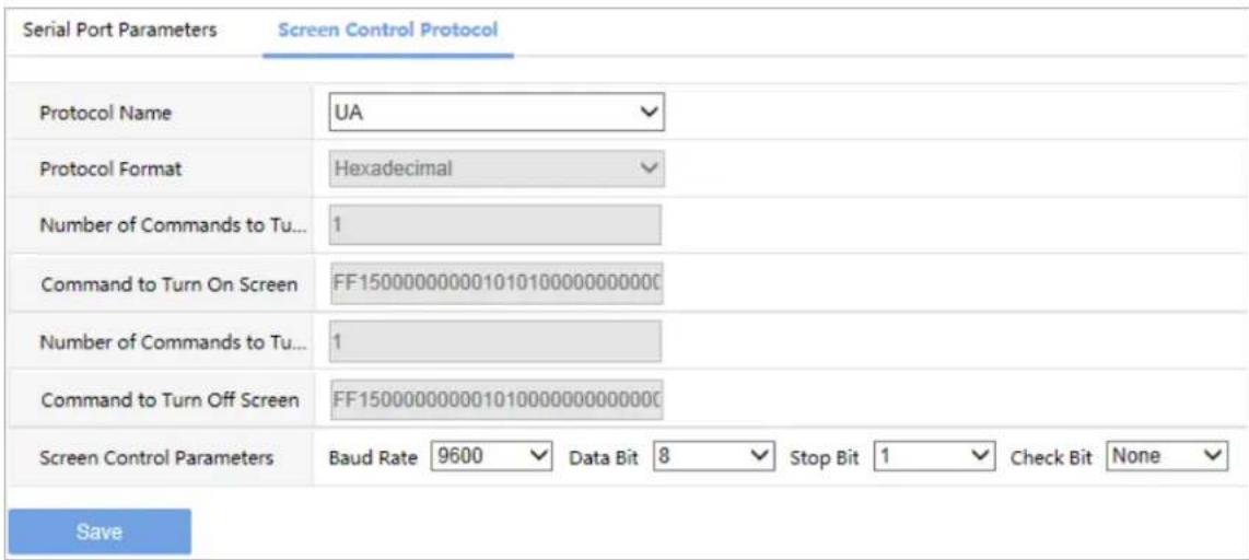
3.3.2 Screen Control Protocol
Select or customize a screen control protocol as required.
text_image
Serial Port Parameters Screen Control Protocol Protocol Name UA Protocol Format Hexadecimal Number of Commands to Tu... 1 Command to Turn On Screen FF150000000001010100000000000 Number of Commands to Tu... 1 Command to Turn Off Screen FF15000000000101000000000000 Screen Control Parameters Baud Rate 9600 Data Bit 8 Stop Bit 1 Check Bit None Save3.4 Play
3.4.1 Play
Set display mode.
3) Click System > Play.
4) The Play page lists the display mode.

text_image
Play Advanced Sync Mode Sync Mode Save3) Click Save.
3.4.2 Advanced
Set what to display when decoding stops.
5) Click System > Play > Advanced
2) Set what to display when decoding stops.

text_image
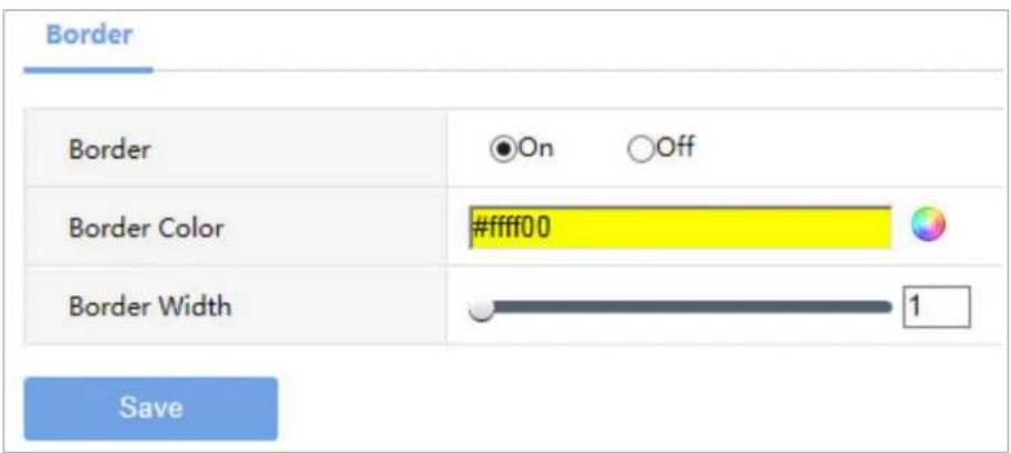
Play Advanced When Decoding Stops Display Last Frame Save3.5 Window
Set Window border.
1) Click System > Window
text_image
Border Border On Off Border Color #ffff00 Border Width 1 Save2) Set the parameters. Some are described in the table below.
| Parameter Description | |
| Border Off by default, displays window border after opening. | |
| Border Color Set border color. | |
| Border Width Set border width. | |
3) Click Save.
3.6 Running Mode
Set the running mode and protocol of the device.
2) Click System > Running Mode.
3) The Running Mode page lists the running mode and protocol

text_image
Running Mode Running Mode Master device Protocol ONVIF Device ID Device ID Server Address Server Port Save3) Click Save.
3.7 Security
Set the security of the device.
3.7.1 Telnet
Enable Telnet if you want to access the device from a computer with Telnet. By default the admin username cannot be changed.
1) Click System > Security > Telnet.

text_image
Telnet SNMPv3 Authentication Secure Password Telnet On Off Save2) Select the check box to enable Telnet, and then click Save.
3.7.2 SNMPv3
Through SNMP the central server synchronizes audio/video channel configurations and some of the scheduled tasks to the device, and the device reports device alarms to the central server.
1) Click System > Security > SNMPv3
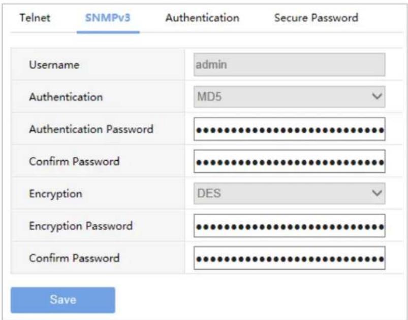
2) This page can't be configured.
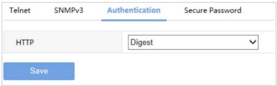
3.7.3 Authentication
Select digest or null in the Authentication page. Digest access authentication is one of the agreed-upon methods a web server can use to negotiate credentials with server.
1) Click System > Security > Authentication
text_image
Telnet SNMPv3 Authentication Secure Password HTTP Digest Save2) Select Digest to enable the digest authentication, and then click Save.
3.7.4 Secure Password
1) Click System > Security > Secure Password.
2) Some parameters are described in the table below.
| Parameter Description | |
| Friendly Password | You must log in with a strong password except in the same network segment or three private network segments (10.X.X.X/8、172.16.X.X/12、192.168.X.X/16). |
| Enhanced Password You | must log in with a strong password. |
3) Select password mode, and then click Save.
4 Network
Set network settings include TCP/IP and Telnet so that the device can communicate with other devices on the network.
4.1 TCP/IP
Assign a static IP address manually, or obtain one using the DHCP server.
1) Click Network > TCP/IP.

text_image
TCP/IP Working ModeLoad Balance Select NICNIC1 IPv4 Address209.2.16.100 IPv4 Subnet Mask255.255.255.0 IPv4 Default Gateway209.2.16.1 MAC Address3E-6A-2C-9C-03-9B Save2) Set the parameters. Some are described in the table below.
| Parameter Description | |
| Working Mode Load Balance. | |
| Select NIC Select the network interface. | |
| IPv4 Address Set the IP Address. | |
| IPv4 Subnet Mask Set the subnet mask. | |
| IPv4 Default Gateway Set the gateway. | |
| MAC Address Display the mac address. |
2) Click to Save.
5 Maintenance
The major functions provided on the Maintenance menu are listed in the table below.
| Parameter Description | |
| Device Status | View device information.For more details, seeDevice Status. |
| Packet Capture Capture packets of the device. | |
| Maintenance | Restart the device.Restore factory default settings.Import and export configuration file.Export diagnostic information.Upgrade the software.For more details, seeMaintenance. |
5.1 Device Status
1) Click Maintenance > Device Status to view information of the device, its basic information, running status, fan status and slot temperature. The following shows an example.
Device Status
Basic Info
| Model | DMC9000 | ||
| Serial No. | 210235C43X1432640810 | Firmware Version | B2101.7.5.210315 |
| Hardware Version | A | Boot Version | UBOOT 201907 |
Running Status
| Running Mode | Master device | ||
| Access Mode | Multi-screen Controller | Protocol | ONVIF |
| System Time | 2021/03/18 17:12:17 | ||
| Running Time | 0 Day(s) 0 Hour(s) 42 Minute(s) | Temperature | 27°C |
| CPU Usage | 6% | Memory Usage | 21% |
Fan Status
| Fan 1 Status | Online | Fan 1 Speed | 4890 |
| Fan 2 Status | Online | Fan 2 Speed | 4740 |
Slot Temperature

bar
| Category | Temperature (°C) | | :--- | :--- | | Motherboard | 27 | | Slot 1/O offline | 0 | | Slot 2/O offline | 0 | | Slot 3/O offline | 0 | | Slot 4/O offline | 0 |Refresh
2) Some are described in the table below.
| Parameter Description | |
| Model The current product model equipment. | |
| Serial No. | The serial number of the equipment. |
| Firmware Version | Device's current software version. |
| Hardware Version Equipment | hardware version of the current. |
| Boot Version Current versions | of bootstrap equipment. |
| Running Mode The operation | of the equipment for the current configuration mode. |
| Access Mode The current access mode of the equipment. | |
| Protocol The current equipment access protocol. | |
| System Time Equipment of the current system time. | |
| Running Time Equipment continuous operation time. | |
| Temperature The temperature of the current equipment. | |
| CPU Usage Current CPU utilization device. | |
| Memory Usage Equipment the current memory usage. | |
| Fan Status If the current fan online. | |
| Fan Speed The fan speed. | |
| Buzzer | On: When the high temperature alarm, the buzzer will beep.Off: When the high temperature alarm, the buzzer won't buzz. |
3) You can view the current boards in the icon types, such as temperature, whether online status information.
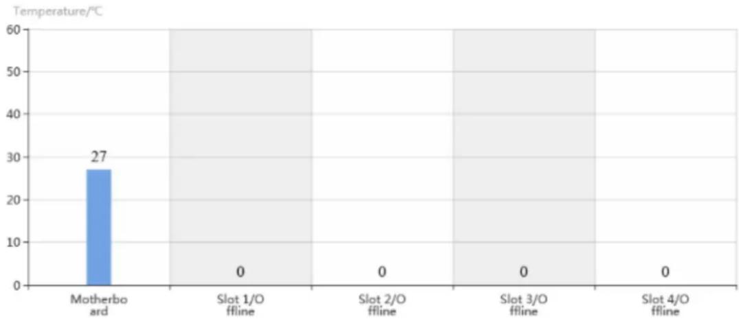
bar
| Category | Temperature (°C) | | :--- | :--- | | Motherboard | 27 | | Slot 1/O offline | 0 | | Slot 2/O offline | 0 | | Slot 3/O offline | 0 | | Slot 4/O offline | 0 |5.2 Packet Capture
1) Click Maintenance > Packet Capture.
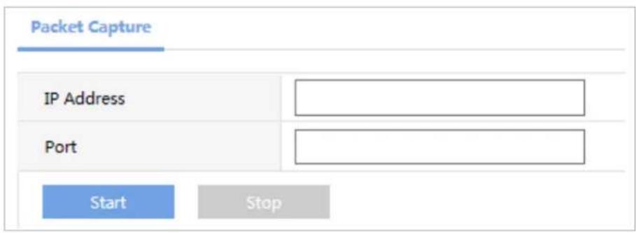
text_image
Packet Capture IP Address Port Start Stop3) Some are described in the table below.
| Parameter Description | |
| IP Address Set the IP address | of the device to capture packets. |
| Port | Set the port number of the device to capture packets. |
5.3 Maintenance
2) Click Maintenance > Maintenance and then perform maintenance operations as needed. You can restart the device, restore some factory default settings, import and export configuration files, export diagnostic information, and upgrade the device.
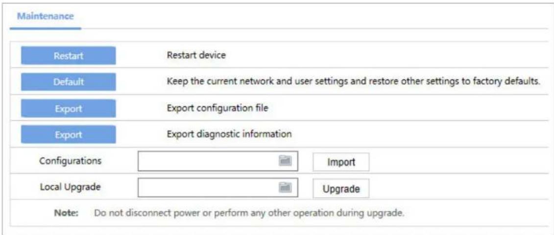
text_image
Maintenance Restart Restart device Default Keep the current network and user settings and restore other settings to factory defaults. Export Export configuration file Export Export diagnostic information Configurations Import Local Upgrade Upgrade Note: Do not disconnect power or perform any other operation during upgrade.6 Specifications
| CHASSIS | VW-CG Series |
| Dimensions (Inch/mm) 17.59" × 18.54" × 5.19" / | 447mm × 471mm × 132mm |
| Weight 31.08 lbs (14.1 Kg) | |
| Power Consumption < 350W | |
| Service Board Slots 10 | |
| Mixed Insertion Support | |
| Control Board Interface | 1x network, 1x Console serial, 3x RS232/RS485 serial,2x USB, 1x RST key, 1x SWAP Hot-swappable key |
| Operation Voltage 100V~ 240V AC 50Hz/60Hz | |
| Temperature 0°C ~ +50°C (Operation) / -40°C ~ | +70°C (Storage) |
| Humidity 0% ~ 90% (Operation) / 0% ~ 95% (Storage) | |
| BOARD TYPE | |
| Signal Input | HDMI x4 / HDMI x8 / Max. mixture of 80 Inputs |
| Signal Output | HDMI x4 / HDMI x8 / Max. mixture of 80 Outputs |
| Input Resolution | XGA:1024x768@60HZ / 720P:1280x720@50HZ /720P:1280x720@60HZ / SXGA:1280x1024@60HZ /WXGA:1440x900@60HZ / UXGA:1600x1200@60HZ /1080P:1920x1080@50HZ / 1080P:1920x1080@60HZ /WUXGA:1920x1200@60HZ |
| SCREEN CONTROL | |
| Number of Windows | Each output can open 8 windows on average |
| The window opening resources of all output can be shared | |
| Up to 32 windows are allowed for each output | |
| Roam and Overlay | The windows can roam at any position on the video wall |
| Supports window overlay | |
| Supports picture-in-picture mode | |
| One-click Layout Create a video wall with an M x N lor fixed layout. | |
| Multiple Video Walls Create & manage 4 video walls w/ different configurations | |
| Scene Management Up to 64 scenes can be saved | |
| ADVANCED | |
| Signal Delay < 100ms | |
| Output Sync | Fully synchronized |
| Power Failure Protection | The current running services and layout will be retained and restored after restart. |
| Seamless Switching Support | |
Specifications subject to change without any notice
7 Product Photos
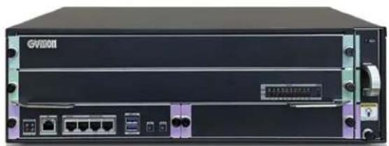
natural_image
Front view of a black GVI00II network equipment rack with ports and switches (no visible text or labels beyond branding)▲ Front View

natural_image
Front view of a black server rack unit with ports and connectors (no visible text or labels)Quarter View
natural_image
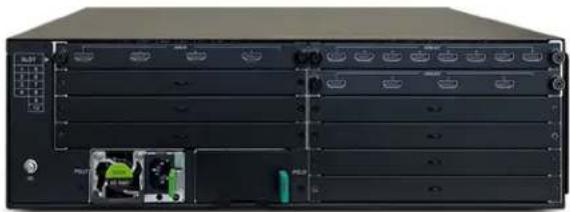
Front view of a black server rack with multiple ports and a green internal component (no visible text or labels)▲ Rear View (The number of In/Outputs are vary)

natural_image
Four identical black electronic equipment units with green circular components, arranged horizontally (no visible text or symbols)▲ Side View

natural_image
Dark rectangular panel with faint vertical lines and corner markers (no text or symbols)Top View